WO2017203595A1 - Dispositif de direction assistée électrique - Google Patents
Dispositif de direction assistée électrique Download PDFInfo
- Publication number
- WO2017203595A1 WO2017203595A1 PCT/JP2016/065287 JP2016065287W WO2017203595A1 WO 2017203595 A1 WO2017203595 A1 WO 2017203595A1 JP 2016065287 W JP2016065287 W JP 2016065287W WO 2017203595 A1 WO2017203595 A1 WO 2017203595A1
- Authority
- WO
- WIPO (PCT)
- Prior art keywords
- signal
- assist
- phase
- steering
- compensation
- Prior art date
- Legal status (The legal status is an assumption and is not a legal conclusion. Google has not performed a legal analysis and makes no representation as to the accuracy of the status listed.)
- Ceased
Links
Images


Classifications
-
- B—PERFORMING OPERATIONS; TRANSPORTING
- B62—LAND VEHICLES FOR TRAVELLING OTHERWISE THAN ON RAILS
- B62D—MOTOR VEHICLES; TRAILERS
- B62D5/00—Power-assisted or power-driven steering
- B62D5/04—Power-assisted or power-driven steering electrical, e.g. using an electric servo-motor connected to, or forming part of, the steering gear
- B62D5/0457—Power-assisted or power-driven steering electrical, e.g. using an electric servo-motor connected to, or forming part of, the steering gear characterised by control features of the drive means as such
- B62D5/046—Controlling the motor
- B62D5/0463—Controlling the motor calculating assisting torque from the motor based on driver input
-
- B—PERFORMING OPERATIONS; TRANSPORTING
- B60—VEHICLES IN GENERAL
- B60W—CONJOINT CONTROL OF VEHICLE SUB-UNITS OF DIFFERENT TYPE OR DIFFERENT FUNCTION; CONTROL SYSTEMS SPECIALLY ADAPTED FOR HYBRID VEHICLES; ROAD VEHICLE DRIVE CONTROL SYSTEMS FOR PURPOSES NOT RELATED TO THE CONTROL OF A PARTICULAR SUB-UNIT
- B60W10/00—Conjoint control of vehicle sub-units of different type or different function
- B60W10/20—Conjoint control of vehicle sub-units of different type or different function including control of steering systems
-
- B—PERFORMING OPERATIONS; TRANSPORTING
- B62—LAND VEHICLES FOR TRAVELLING OTHERWISE THAN ON RAILS
- B62D—MOTOR VEHICLES; TRAILERS
- B62D5/00—Power-assisted or power-driven steering
- B62D5/04—Power-assisted or power-driven steering electrical, e.g. using an electric servo-motor connected to, or forming part of, the steering gear
- B62D5/0457—Power-assisted or power-driven steering electrical, e.g. using an electric servo-motor connected to, or forming part of, the steering gear characterised by control features of the drive means as such
- B62D5/046—Controlling the motor
- B62D5/0472—Controlling the motor for damping vibrations
-
- B—PERFORMING OPERATIONS; TRANSPORTING
- B62—LAND VEHICLES FOR TRAVELLING OTHERWISE THAN ON RAILS
- B62D—MOTOR VEHICLES; TRAILERS
- B62D6/00—Arrangements for automatically controlling steering depending on driving conditions sensed and responded to, e.g. control circuits
- B62D6/008—Control of feed-back to the steering input member, e.g. simulating road feel in steer-by-wire applications
-
- B—PERFORMING OPERATIONS; TRANSPORTING
- B62—LAND VEHICLES FOR TRAVELLING OTHERWISE THAN ON RAILS
- B62D—MOTOR VEHICLES; TRAILERS
- B62D6/00—Arrangements for automatically controlling steering depending on driving conditions sensed and responded to, e.g. control circuits
- B62D6/08—Arrangements for automatically controlling steering depending on driving conditions sensed and responded to, e.g. control circuits responsive only to driver input torque
- B62D6/10—Arrangements for automatically controlling steering depending on driving conditions sensed and responded to, e.g. control circuits responsive only to driver input torque characterised by means for sensing or determining torque
Definitions
- This invention relates to an electric power steering apparatus that outputs an assist torque based on a steering torque signal.
- the steering torque that is substantially proportional to the steering torque is determined, and the driver's steering force is reduced by increasing the torque proportional gain (also referred to as assist gradient), which is an amplification factor of the proportional relationship between the steering torque and the assist torque. It has been attempted to improve the driver's feeling by suppressing vibrations such as oscillation of a control system that occur with an increase in gain.
- an electric power steering apparatus having an assist curve that determines an assist torque command in accordance with a vehicle speed and an input torque, that is, a steering torque
- an instantaneous value of the assist torque command with respect to the steering torque is determined from the output of the vehicle speed, the steering torque, and the assist curve.
- An electric power steering apparatus includes a gradient detection circuit for calculating a simple assist gradient and changes the pole of the phase compensator so as to be approximately proportional to the instantaneous assist gradient (see, for example, Patent Document 1).
- the steering compensator and the vehicle speed are used instead of the assist gradient without calculating the assist gradient, and the frequency characteristic of the phase compensator can be changed according to the magnitude of the steering torque and the vehicle speed.
- an electric power steering apparatus configured to do so (for example, see Patent Document 2).
- the assist gradient of the assist curve generated by the assist torque command generation unit tends to be larger when the steering torque is larger.
- the assist gradient which is the gradient of the assist curve as the assist torque command generation unit, is always based on the steering torque, the assist torque command, and the vehicle speed. Since the calculation is performed in real time, there is a problem that the calculation amount is large and the load on the CPU is high. In order to avoid computing in real time, it is possible to prepare in advance a table for outputting the assist gradient with respect to the steering torque and the vehicle speed, but the table is multidimensional and has a huge amount of data. Therefore, there is a problem that the amount of memory used becomes excessive.
- the conventional electric power steering control device disclosed in Patent Document 2 does not use an enormous table for referring to the assist gradient from the steering torque as described above, but substitutes the assist gradient with a steering torque signal. Therefore, the assist gradient cannot be accurately captured when the assist gradient becomes small in a region where the steering torque is large or when the gradient changes depending on the vehicle speed. Therefore, a filter characteristic and phase compensator suitable for when the assist torque is large even though the assist gradient is small, or a filter characteristic and phase compensator suitable for when the assist torque is small although the assist gradient is large are used. There was a problem that the stability and responsiveness were impaired.
- the present invention has been made in order to solve the above-described problems in the conventional electric power steering apparatus, and has stability and responsiveness corresponding to the assist gradient while suppressing the calculation load and the storage capacity.
- An object of the present invention is to provide an electric power steering apparatus provided.
- the electric power steering device is: An electric power steering apparatus comprising: a motor that outputs assist torque based on a steering torque signal from a torque sensor that detects steering torque; and a control device that controls the assist torque of the motor,
- the controller is An assist torque command calculator for calculating and outputting an assist torque command signal for generating the assist torque in the motor;
- a high frequency compensation unit that outputs a high frequency compensation signal obtained by filtering the high frequency component of the assist torque command signal and multiplying by a gain;
- the assist torque command calculation unit A corrected steering torque signal generated by negative feedback or positive feedback of the high frequency compensation signal to the steering torque signal is input, Outputting an assist torque command signal in accordance with the input corrected steering torque signal; Configured as It is characterized by this.
- the electric power including the motor that outputs the assist torque based on the steering torque signal from the torque sensor that detects the steering torque, and the control device that controls the assist torque of the motor.
- the steering device wherein the control device calculates and outputs an assist torque command signal for causing the motor to generate the assist torque, and filters a high frequency component of the assist torque command signal
- a high-frequency compensation unit that outputs a high-frequency compensation signal multiplied by a gain
- the assist torque command calculation unit is a post-correction generated by negative feedback or positive feedback of the high-frequency compensation signal to the steering torque signal
- a steering torque signal is input, and according to the input corrected steering torque signal Is configured so as to output a Shisutotoruku command signal, while suppressing the computing load and memory capacity, it is possible to improve the stability and responsiveness in accordance with the assist gradient.
- FIG. 10 is an input / output characteristic diagram showing characteristics of an assist map in the electric power steering apparatus according to the first to fifth embodiments of the present invention.
- FIG. 3 is a Bode diagram showing a transmission characteristic from a compensated steering torque signal to an assist torque command signal in the electric power steering apparatus according to Embodiment 1 of the present invention. It is a block diagram which shows the structure of the control apparatus in the conventional electric power steering apparatus. It is a Bode diagram which shows the transmission characteristic from a steering torque signal to an assist torque command signal in the conventional electric power steering device. It is a Bode diagram which compares and shows each open loop circuit transfer function in the electric power steering device by Embodiment 1 of this invention, and the conventional electric power steering device. It is a block diagram which shows the structure of the control apparatus in the electric power steering apparatus by Embodiment 2 of this invention.
- FIG. 1 is a configuration diagram showing the configuration of a vehicle steering system including an electric power steering device according to Embodiments 1 to 5 of the present invention.
- a vehicle steering system includes a steering wheel 1 operated by a vehicle driver, a steering shaft 2 connected to the steering wheel 1, a rack and pinion gear 12 connected to the steering shaft 2, A steering wheel 1, a steering shaft 2, and wheels 3 and 4 steered by a driver via a rack and pinion gear 12 are provided.
- the vehicle steering system includes the electric power steering apparatus according to Embodiment 1 of the present invention.
- the electric power steering apparatus includes a motor 5 that generates assist torque for assisting steering by the driver, a reduction gear 7 that transmits the output of the motor 5 to the steering shaft 2, and a torque sensor 8 that detects the steering torque of the driver. And a control device 9 for driving the motor 5 based on the steering torque detected by the torque sensor 8 and the vehicle speed detected by the vehicle speed sensor 13, and a motor rotation angle sensor 6 for detecting the rotation angle of the motor 5.
- a power source 11 configured by a battery mounted on the vehicle supplies power to the control device 9 and the motor 5.
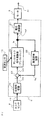
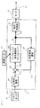
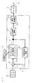
- FIG. 2 is a block diagram showing the configuration of the control device in the electric power steering apparatus according to Embodiment 1 of the present invention.
- the control device 9 includes, as components, an assist map as an assist torque command calculation unit 20, a current control unit 21, a phase compensator 24 as a first phase compensator, and a high frequency compensation unit. 22 and a subtractor 23.
- the components of the control device 9 are configured as microcomputer software.
- the microcomputer includes a known central processing unit (hereinafter referred to as CPU), read only memory (hereinafter referred to as ROM), random access memory (hereinafter referred to as RAM), interface (hereinafter referred to as IF) and the like. Then, a program stored in the ROM is sequentially extracted and a desired calculation is performed by the CPU, and a result of the calculation is temporarily stored in the RAM, thereby executing a software program to perform a predetermined control operation.
- CPU central processing unit
- ROM read only memory
- RAM random access memory
- IF interface
- FIG. 1 the steering torque applied to the steering wheel 1 by a driver (not shown) is transmitted from the torsion bar of the torque sensor 8 to the rack of the rack and pinion gear 12 via the steering shaft 2, and the wheels 3, 4 is steered.
- the output torque generated by the motor 5 is transmitted to the steering shaft 2 via the reduction gear 7 to reduce the steering torque applied by the driver during steering.
- the motor 5 for example, an AC motor such as a permanent magnet type synchronous motor or an induction motor, or a DC motor is used.
- the torque sensor 8 includes a torsion bar, and has a function of converting the twist angle of the torsion bar into an electric signal.
- the torque sensor 8 converts the torsion angle of the torsion bar into an electric signal and outputs it as a steering torque signal ⁇ 0.
- the vehicle speed sensor 13 detects the traveling speed of the vehicle and outputs a vehicle speed signal Vx.
- the steering torque signal ⁇ 0 may be simply referred to as “steering torque ⁇ 0”
- the vehicle speed signal Vx may be simply referred to as “vehicle speed Vx”.
- the control device 9 calculates a motor current command signal Iref corresponding to the direction and value of the output torque of the motor 5 according to the steering torque ⁇ 0 detected by the torque sensor 8 and the vehicle speed Vx detected by the vehicle speed sensor 13.
- the current of the motor 5 is controlled based on the generated current command signal Iref.
- the motor 5 is driven based on the current controlled by the control device 9 and applies assist torque AT to the steering shaft 2 via the reduction gear 7.
- the phase compensator 24 performs phase compensation for decreasing or increasing the high-frequency gain on the steering torque ⁇ 0 detected by the torque sensor, and obtains a compensated steering torque signal Tsca that is phase-compensated.
- the phase compensator 24 is also referred to as a phase compensator.
- the phase compensator 24 has a function of increasing the phase characteristic at a frequency near the gain crossover frequency of the loop transfer function in the closed loop system related to the assist torque AT, for example, a phase having the frequency characteristic shown in FIG. It is assumed that it is composed of a lead compensator.
- phase 3 is a Bode diagram showing the frequency characteristics of the phase advance compensator as the phase compensator in the electric power steering apparatus according to Embodiment 1 of the present invention, and the vertical axis indicates the phase [deg]. And gain [dB], respectively, and the horizontal axis represents frequency [Hz].
- the lead phase compensator as the phase compensator 24 has a function of increasing the phase characteristics at frequencies 10 1 [HZ] to 10 2 [Hz] near the gain crossover frequency.
- the subtractor 23 corrects the compensated steering torque signal Tsca by subtracting the high frequency compensation signal Thc from the high frequency compensation unit 22 described later from the compensated steering torque signal Tsca, and the corrected steering torque signal Tscb is obtained. obtain.
- the assist map as the assist torque command calculating unit 20 calculates an assist torque command signal Ia corresponding to the assist torque AT based on the corrected steering torque signal Tscb.
- the assist torque command signal Ia is also referred to as an assist current command signal.
- the assist torque command signal Ia is referred to as an assist torque command signal.
- the assist torque command signal Ia becomes the motor current command signal Iref for the motor as it is, but in addition to the compensation control generally used, for example, the steering frequency.
- an assist torque command signal Ia is obtained by adding or subtracting a correction value by inertia compensation control that compensates for the influence of increase in motor inertia or a correction value by viscosity compensation control that increases viscosity to the assist torque command signal Ia. You may make it correct
- a vehicle speed signal Vx is also input to the assist map as the assist torque command calculation unit 20, and the input / output characteristics of the assist map are changed depending on the vehicle speed.
- FIG. 4 is a block diagram showing the configuration of the high frequency compensation unit in the electric power steering apparatus according to Embodiments 1 to 5 of the present invention. As shown in FIG. 4, the high frequency compensation unit 22 includes a high pass filter 30 and a gain 31.
- the high-pass filter 30 filters the high-frequency component of the assist torque command signal Ia without attenuating, and attenuates the low-frequency component.
- a first-order filter HPF (s) having a transfer function represented by the following equation (1) may be used as the high-pass filter 30, a first-order filter HPF (s) having a transfer function represented by the following equation (1).
- the high frequency component refers to a frequency component having a frequency equal to or higher than the cut-off frequency ⁇ h of the high pass filter 30.
- HPF (s) s / (s + ⁇ h) (1)
- s represents a Laplace operator.
- the gain 31 multiplies the output of the high pass filter 30 by the gain k and outputs the result as a high frequency compensation signal Thc.
- the assist torque command signal Ia calculated by the assist torque command calculation unit 20 is directly input to the current control unit 21 as the motor current command signal Iref.
- the current control unit 21 controls the motor current so as to coincide with the input motor current command signal Iref.
- the current control unit 21 includes, for example, a drive circuit including an H bridge circuit or an inverter circuit configured by a semiconductor switching element, and an input motor current command signal Iref and a motor current that actually flows through the motor. And the switching element of the drive circuit is controlled so that the deviation between the motor current command signal Iref and the motor current that actually flows through the motor becomes zero.
- the drive circuit is PWM-controlled by a PWM (Pulse Width Modulation) signal as a voltage command corresponding to the motor current command signal Iref, for example, and supplies the drive current to the motor 5.
- the motor 5 generates an assist torque AT as an output torque corresponding to the supplied drive current.
- the high-frequency compensation signal Thc which is a signal obtained by multiplying the high-frequency component of the assist torque command signal Ia by the gain k, is negatively fed back to the post-compensation steering torque signal Tsca by the subtractor 23, and the corrected steering torque signal Tscb is obtained.
- the high-frequency component of the post-compensation steering torque signal Tsca is accompanied by the post-compensation steering torque signal Tsca as a part of the post-correction steering torque signal Tscb generated via the subtracter 23, and the assist map as the assist torque command calculation unit 20 Is input.
- the assist map as the assist torque command calculation unit 20 is usually configured in a non-linear manner.
- the torque proportional gain which is an amplification factor at the operating point of the assist map, is referred to herein as an assist gradient.
- the corrected steering torque signal Tscb input to the assist torque command calculation unit 20 is amplified according to the assist gradient of the assist map, and is output from the assist torque command calculation unit 20 as an assist torque command signal Ia.
- the high-frequency component input to the assist torque command calculation unit 20 accompanying the post-compensation steering torque signal Tsca as part of the corrected steering torque signal Tscb is the assist torque output from the assist torque command calculation unit 20.
- the command signal Ia is included as a high frequency component and is input to the high frequency compensation unit 22 again.
- control device 9 has a loop in which the high-frequency component is repeatedly processed by the assist torque command calculation unit 20 using the compensated steering torque signal Tsca as a flow force, so that only the high-frequency component is an assist torque command. It is configured to receive the processing of the arithmetic unit 20 repeatedly.
- the low-frequency component is attenuated by passing through the high-pass filter 30 of the high-frequency compensation unit 22, and therefore is hardly affected by the high-frequency compensation signal Thc. Therefore, the low frequency component of the post-compensation steering torque signal Tsca is simply amplified based on the assist gradient of the assist map without being repeatedly subjected to the action of the assist map as the assist torque command calculation unit 20, and the assist torque. It becomes a low frequency component of the command signal Ia.
- the compensated steering torque signal Tsca to the assist torque command signal Ia in response to the assist gradient can be changed.
- the characteristic from the compensated steering torque signal Tsca to the assist torque command signal Ia is basically a characteristic obtained by multiplying the phase delay compensation characteristic and the assist gain.
- the phase lag compensation characteristic is variable with respect to the assist gradient.
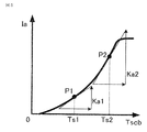
- FIG. 5 is an input / output characteristic diagram showing assist map characteristics in the electric power steering apparatus according to the first to fifth embodiments of the present invention, and shows the input / output of the assist map at a certain vehicle speed. The characteristics are shown.
- the vertical axis represents the assist torque command signal Ia
- the horizontal axis represents the corrected steering torque signal Tscb.
- the operating point P1 is an operating point.
- the instantaneous gradient of the assist torque command signal Ia with respect to the corrected steering torque signal Tscb at that time is the assist gradient Ka1 as a torque proportional gain at the operating point P1.
- the assist gradient Ka2 as the torque proportional gain is more than the assist gradient Ka1 as the torque proportional gain at the operating point P1. It is a large value.
- the low-frequency component of the post-compensation steering torque signal Tsca is simply amplified based on the assist gradient without being repeatedly subjected to the assist map, and becomes the low-frequency component of the assist torque command signal Ia. Therefore, in the case of the operating point P1 of the assist torque map, the low frequency component of the assist torque command signal Ia is a value obtained by multiplying the low frequency component of the compensated steering torque signal Tsca by the assist gradient Ka1, and in the case of the operating point P2, the operation is performed. The value is obtained by multiplying the assist gradient Ka2 larger than the assist gradient Ka1 at the point P1.
- the high-frequency component of the compensated steering torque signal Tsca determines the operating point of the assist map depending on the low-frequency component.
- the high-frequency component of the assist torque command signal Ia is the corrected steering torque signal.
- a value obtained by multiplying Tscb by the assist gradient Ka1 is subtracted from the compensated steering torque signal Tsca again as the high-frequency compensation signal Thc, and is repeatedly multiplied by the assist gradient Ka1.
- the value is obtained by multiplying the assist gradient Ka2 larger than the assist gradient Ka1.
- the high frequency component of the compensated steering torque signal Tsca increases as the assist gradient increases, so that the high frequency compensation signal Thc increases and the subtraction amount in the subtracter 23 also increases. Therefore, the assist torque command signal Ia is derived from the compensated steering torque signal Tsca. The phase lag compensation effect up to is increased.
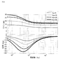
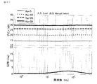
- FIG. 6 is a Bode diagram showing a transfer characteristic from the compensated steering torque signal to the assist torque command signal in the electric power steering apparatus according to Embodiment 1 of the present invention, from the compensated steering torque signal Tsca.
- the frequency response of the transfer characteristic up to the assist torque command signal Ia is shown, the vertical axis shows the phase [deg] and the gain [dB], and the horizontal axis shows the frequency [Hz].
- the thin solid line is the assist gradient Ka is “5”
- the thin wavy line is the assist gradient Ka is “10”
- the thick wavy line is the assist gradient Ka is “20”
- the thick solid line is the assist gradient Ka is “30”.
- Phase [deg] and gain [dB] are shown respectively.
- the magnitude of the gain characteristic shows a value substantially corresponding to the assist gradient Ka, and increases as the assist gradient Ka increases. ing.
- the larger the assist gradient Ka the larger the amount of gain decrease and the larger the phase lag compared to the lower frequency band. It turns out that it changes in response to.
- FIG. 7 is a block diagram showing a configuration of a control device in a conventional electric power steering apparatus, and shows an example of a configuration using a phase compensator 40 having a fixed characteristic.
- the same reference numerals as those in FIG. 2 denote the same or corresponding parts.
- FIG. 8 is a Bode diagram showing transfer characteristics from a steering torque signal to an assist torque command signal in a conventional electric power steering apparatus. 7 and 8, the phase lag compensation effect from the post-compensation steering torque signal Tsca to the assist torque command signal Ia is obtained by using the phase compensator 40 having a fixed characteristic. Therefore, unlike the case of the electric power steering apparatus according to Embodiment 1 of the present invention, as shown in FIG. 8, the conventional apparatus shown in FIG. The amount is constant regardless of the assist gradient.
- the transfer function from the compensated steering torque signal Tsca to the assist torque command signal Ia is expressed in relation to the assist gradient Ka of the assist map. It explains using.
- a corrected steering torque signal Tscb obtained by negatively feeding back the high frequency compensation signal Thc to the post-compensation steering torque signal Tsca can be expressed by the following equation (3).
- Tscb Tsca ⁇ Thc (Equation 3)
- the transfer function Ga (s) from the compensated steering torque signal Tsca to the assist torque command signal Ia is expressed by the following formula: (5).
- Ga (s) Ka ⁇ (s + ⁇ h) / ⁇ (1 + k ⁇ Ka) ⁇ s + ⁇ h ⁇ (5)
- Ia Ga (s) ⁇ Tsca (6)
- the frequency characteristic shown in FIG. 6 is just a plot of the value of Equation (5), and the transfer function Ga (s) from the compensated steering torque signal Tsca to the assist torque command signal Ia shown in Equation (5).
- ) Includes an assist gradient Ka in the denominator ⁇ (1 + k ⁇ Ka) ⁇ s + ⁇ h ⁇ of the equation (5), and its pole can be expressed by the following equation (7). ⁇ h / (1 + k ⁇ Ka) (7)
- phase compensation characteristic from the post-compensation steering torque signal Tsca to the assist torque command signal Ia changes depending on the assist gradient Ka. Since the zero point of the numerator of the above formula (5) is fixed at the cut-off frequency ⁇ h of the high-pass filter 30, the break frequency on the high frequency side of the phase lag compensation characteristic is constant with respect to the assist gradient. The pole indicates the break frequency on the low frequency side of the phase lag compensation characteristic, and the break frequency decreases as the assist gradient Ka increases. Accordingly, in the phase compensation characteristic from the post-compensation steering torque signal Tsca to the assist torque command signal Ia, as the assist gradient Ka increases, the amount of gain decrease in the high frequency band increases as compared with the low frequency band, and the phase lag occurs. It will have the characteristic of increasing quantity.
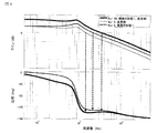
- FIG. 9 is a Bode diagram comparing the open-loop circuit transfer functions of the electric power steering apparatus according to Embodiment 1 of the present invention and the conventional electric power steering apparatus.
- the vertical axis in FIG. 9 indicates the phase [deg] and the gain “dB”, the horizontal axis indicates the frequency [Hz], and the thick solid line indicates the first embodiment of the present invention when the assist gradient Ka is 30.
- the one-round transfer function according to the configuration of FIG. 1 and the one-round transfer function according to the configuration of the conventional device shown in FIG. 7 are designed so that the configuration of the first embodiment and the configuration of the attacking device have the same characteristics.
- the phase compensator 24 in the configuration of the first embodiment of the present invention is configured so as to have the characteristics shown in FIG. 3 as phase lead compensation as described above, and the configuration of the conventional apparatus shown in FIG.
- the phase compensator 24 in the same manner is also configured.
- the phase compensation characteristic from the post-compensation steering torque signal Tsca to the assist torque command signal Ia in the configuration of the first embodiment of the present invention has a high gain crossover frequency when the assist gradient Ka is “30”. Therefore, as shown in FIG. 6, the gain is designed to sufficiently decrease at a high frequency near the gain crossover frequency. Further, the phase compensation characteristic from the post-compensation steering torque signal Tsca to the assist torque command signal Ia in the configuration of the conventional apparatus shown in FIG. 8 is also obtained when the assist gradient Ka is “30”. It is comprised so that it may become the same characteristic as the structure of embodiment.
- the loop transfer function when the assist gradient Ka is as large as “30” has a large phase advance amount at the gain crossover frequency as shown in FIG. 9, and a sufficient margin for the phase advance amount can be secured. ing.
- the round transfer function by the conventional apparatus when the assist gradient Ka is as small as “5” will be described.
- the phase compensation characteristic is constant with respect to the assist gradient Ka
- the frequency characteristic of the control device is simply proportional to the assist gradient Ka
- the round transfer function is also simply proportional to the assist gradient Ka. To do.
- the gain diagram according to the configuration of the conventional apparatus moves in parallel by the amount of decrease in the assist gradient Ka, and the phase characteristic becomes constant regardless of the assist gradient Ka.
- the round trip transfer function of the conventional apparatus when the assist gradient Ka is small as “5” is as shown by a thin broken line in FIG. 9 and is placed in a low frequency band of 10 [Hz] or less. It can be seen that the phase delay compensation is too effective, the gain is low, the phase is also delayed, and the steering response is low. Further, the phase delay compensation is excessively effective, and as a result, the gain crossover frequency is lowered to a frequency at which the phase characteristic is minimized, and the phase margin is lowered as compared with the case where the assist gradient Ka is “30”.
- the phase compensation characteristic from the post-compensation steering torque signal Tsca to the assist torque command signal Ia has a phase delay effect as shown in FIG. 6 when the assist gradient Ka is small. Is small, the gain reduction in the high frequency band is slight, and the amount of phase delay is small. Therefore, as shown by the dark solid line in FIG. 9, the loop transfer function has a gain characteristic larger than that of the conventional device indicated by the broken line and a phase in a low frequency region of 10 Hz or lower. It can be seen that the steering response is high.
- the phase delay amount of the control device can be reduced, so that the phase characteristic of the loop transfer function is also small, and as a result, the phase margin at the gain crossover frequency is improved as compared with the conventional device.
- Steering response is the speed at which the actual steering angle responds when the driver inputs steering torque to the steering wheel.
- the steering response becomes higher as the gain and the phase are higher in a low frequency region of about 10 [Hz] or less in terms of a round transfer function.
- phase compensation when the phase compensation is compared with the conventional apparatus designed to optimize the characteristics when the assist gradient is large, according to the configuration of the first embodiment of the present invention, when the assist gradient is large, While ensuring the same phase margin and gain margin as the device, when the assist gradient is small, the steering response can be improved and the phase margin can be improved compared to the conventional device. be able to.
- phase margin decreases, according to the configuration of the first embodiment of the present invention, as the assist gradient increases, the amount of decrease in the high frequency gain can be increased as compared with the low frequency band. The effect that it can suppress and can fully ensure a phase margin can be acquired.
- the electric power steering apparatus includes the assist torque command calculation unit that outputs the assist torque command signal, and the high frequency compensation that filters the high frequency component of the assist torque command signal and multiplies the gain.
- a high-frequency compensation unit that outputs a signal, a corrected steering torque signal obtained by negatively feeding back the high-frequency compensation signal to the steering torque signal is input to the assist torque command calculation unit, and the assist torque command calculation unit assists according to the corrected steering torque signal. Since the torque command signal is configured to be output, the frequency characteristic of the phase compensation characteristic from the steering torque signal to the assist torque command signal can be changed according to the assist gradient of the assist torque command calculation unit. Compared to conventional devices using a normal phase compensator that does not change according to the assist gradient It can be obtained a remarkable effect that it is possible to improve the steering response and stability.
- the very simple configuration of the high-frequency compensator and negative feedback as described above can achieve the same amount of computation as a conventional phase compensator that does not change according to the conventional assist gradient, and the assist gradient is calculated sequentially.
- a significant effect that the amount of computation can be greatly reduced can be obtained.
- the stability and responsiveness are impaired at the operating point where the correlation between the assist gradient and the steering torque is low.
- the phase compensation characteristic can be changed in response to the assist gradient itself, so that stability and responsiveness are not impaired. An effect can be obtained.
- the electric power steering apparatus includes a phase compensator 24 that outputs a compensated steering torque signal in which the phase of the steering torque signal is compensated, and after the phase compensation of the high frequency compensation signal, the compensated steering is performed. Since it is configured to negatively feed back to the torque signal, the phase lag compensation characteristic from the steering torque signal Tsca to the assist torque command signal Ia realized by the high frequency compensator and the phase advance by the phase compensator for phase compensation of the steering torque signal Since characteristics can be combined and phase lag can be advanced and compensated, an unprecedented remarkable effect that stability can be improved by lowering the gain crossover frequency and improving the phase margin can be obtained.
- FIG. 10 is a block diagram showing the configuration of the control device in the electric power steering apparatus according to Embodiment 2 of the present invention.
- the difference from the configuration of Embodiment 1 described above is the subtractor 23. Is changed to the adder 25, and the setting of the frequency characteristics of the phase compensator 24 and the high frequency compensator 22 is changed. Otherwise, the configuration is the same as that of the first embodiment. . In the following description, differences from the configuration of the first embodiment will be mainly described.
- the phase compensator 24 performs phase compensation for lowering or increasing the high-frequency gain on the steering torque signal ⁇ 0 detected by the torque sensor 8, and obtains a compensated steering torque signal Tsca.
- the phase compensator 24 is also referred to as a phase compensator.
- the phase compensator 24 reduces the gain crossover frequency of the loop transfer function in the closed loop system related to the assist torque AT, and increases the phase characteristic near the crossover frequency.
- a phase lag advance compensation function having frequency characteristics as shown in FIG. 11 is provided. That is, FIG. 11 is a Bode diagram showing a phase compensator in the electric power steering apparatus according to Embodiment 2 of the present invention, in which the vertical axis indicates the phase [deg] and the gain “dB”. The axis indicates the frequency [Hz].
- the amount of phase advance is suppressed to the minimum necessary to suppress an increase in gain on the high frequency band side, specifically, lower than a low frequency of 0.5 [Hz] or less. It is suppressed to gain. This prevents the control device from amplifying high frequency noise unnecessarily.
- the high frequency compensation signal Thc described in the first embodiment is added to the compensated steering torque signal Tsca by the adder 25, thereby correcting the compensated steering torque signal Tsca and correcting the corrected steering torque signal Tscb. Get.
- the high-frequency compensation signal Thc which is a signal obtained by multiplying the high-frequency component of the assist torque command signal Ia by a gain, is a steering torque signal Tsca as a part of the corrected steering torque signal Tscb that has been positively fed back to the corrected steering torque signal Tsca and corrected. Therefore, it is amplified according to a torque proportional gain as an assist gradient, which is an amplification factor at an operating point of an assist map that is nonlinearly configured, and a high frequency component is added to the assist torque command signal Ia. And input to the high frequency compensation unit 22 again.
- the high-frequency component of the post-compensation steering torque signal Tsca is positively fed back to the post-compensation steering torque signal Tsca via the assist map and the high-frequency compensation unit 22, and the high-frequency component is added to the post-compensation steering torque signal Tsca.
- the characteristic from the steering torque signal Tsca to the assist torque command signal Ia is basically a characteristic obtained by multiplying the phase advance compensation characteristic and the assist gain.
- the phase lead compensation characteristic is configured to be variable with respect to the assist gradient.
- the operating point of the assist map is determined depending on the low-frequency component of the high-frequency component of the compensated steering torque signal Tsca.
- the high-frequency component of the assist torque command signal Ia is The torque signal Tscb is multiplied by the assist gradient Ka1, and is added again to the post-compensation steering torque signal Tsca as the high frequency compensation signal Thc, and is repeatedly multiplied by the assist gradient Ka1.
- the value is obtained by multiplying the assist gradient Ka2 larger than the assist gradient Ka1. Accordingly, the high frequency component of the compensated steering torque signal Tsca increases as the assist gradient increases, so that the high frequency compensation signal Thc increases and the amount of addition in the adder 25 also increases. Therefore, the assist torque command signal Ia from the compensated steering torque signal Tsca increases. The phase lead compensation effect up to is increased.
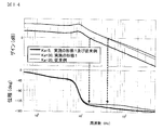
- FIG. 12 is a Bode diagram showing transfer characteristics from the steering torque signal to the assist torque command signal in the electric power steering apparatus according to Embodiment 2 of the present invention, and the vertical axis indicates the phase [deg] and the gain. “DB” is shown, and the horizontal axis shows the frequency [Hz].
- the magnitude of the gain characteristic shows the same value as the assist gradient, and increases as the assist gradient increases.
- the higher frequency band the larger the assist gradient, the greater the gain increase and the phase advance amount compared to the lower frequency band, and the phase advance compensation effect is sensitive to the assist gradient. You can see that it is changing. Further, when the assist gradient is small, the increase amount of the gain in the high frequency band with respect to the low frequency band is small, and it is possible to prevent amplification of high frequency noise.
- FIG. 13 is a Bode diagram showing the transfer characteristic from the steering torque signal to the assist torque command signal in the conventional electric power steering apparatus, and the vertical axis indicates the phase [deg] and the gain “dB”. The horizontal axis represents frequency [Hz].
- the phase compensator effect from the post-compensation steering torque signal Tsca to the assist torque command signal Ia is obtained using the phase compensator 40. Therefore, as shown in FIG. 13, the amount of increase in the gain of the high frequency and the amount of phase advance compared to the low frequency are constant regardless of the assist gradient.
- the transfer function from the post-compensation steering torque signal Tsca to the assist torque command signal Ia is expressed using an equation for the assist gradient Ka of the assist map. I will explain.
- the corrected steering torque signal Tscb obtained by positively feeding back the high frequency compensation signal Thc to the post-compensation steering torque signal Tsca can be expressed by the following equation (8).
- Tscb Tsca + Thc (8)
- the transfer function Ga (s) from the compensated steering torque signal Tsca to the assist torque command signal Ia can be expressed by the following equation. it can.
- Ga (s) Ka ⁇ (s + ⁇ h) / ⁇ (1 ⁇ k ⁇ Ka) ⁇ s + ⁇ h ⁇ (9)
- the frequency characteristic shown in FIG. 12 is just a plot of equation (9).
- equation (9) the transfer function Ga (s) from the compensated steering torque signal Tsca to the assist torque command signal Ia
- the denominator ⁇ (1-k ⁇ Ka) ⁇ s + ⁇ h ⁇ includes an assist gradient Ka, and its pole can be expressed by the following equation (10). ⁇ h / (1-k ⁇ Ka) (10)
- phase compensation characteristic from the post-compensation steering torque signal Tsca to the assist torque command signal Ia changes depending on the assist gradient Ka.
- the point at which the numerator of Equation (9) becomes zero is fixed at the cut-off frequency ⁇ h of the high-pass filter 30 shown in FIG. 4, so that the break frequency on the low frequency band side of the phase advance compensation characteristic is relative to the assist gradient. It is constant.
- the pole shown in Equation (10) indicates the break frequency on the high frequency side of the phase lead compensation characteristic, and the higher the assist gradient Ka, the higher the pole. Therefore, in the phase compensation characteristic from the post-compensation steering torque signal Tsca to the assist torque command signal Ia, the larger the assist gradient Ka, the larger the gain increase in the high frequency band compared to the low frequency band, and the phase advance. It will have the characteristic of increasing quantity.
- FIG. 14 is a Bode diagram showing a comparison of the open-loop circuit transfer functions in the electric power steering apparatus according to Embodiment 2 of the present invention and the conventional electric power steering apparatus. [Deg] and gain “dB” are shown, and the horizontal axis shows the frequency [Hz].
- FIG. 14 shows a circuit transfer function in the configuration according to the second embodiment of the present invention and a circuit transfer function in the configuration of the conventional apparatus shown in FIGS.
- the thick solid line shows the one-round transfer function according to the configuration of the second embodiment of the present invention and the one-round transfer function according to the configuration of the conventional apparatus when the assist gradient Ka is “5”. These are configured to have the same characteristics.
- the phase compensator 24 has the characteristics shown in FIG. The same applies to the configuration of the conventional apparatus in FIG.
- the gain crossover frequency when the assist gradient Ka is “5” can be read as approximately 16 [Hz] from FIG. 9, and the phase compensator 24 is configured to obtain the phase advance amount at this frequency.
- the phase compensation characteristic from the post-compensation steering torque signal Tsca to the assist torque command signal Ia has an assist gradient Ka of “5” as shown in FIG. In this case, the high-frequency gain is not increased as much as possible, and the phase is advanced to the minimum necessary.
- the phase compensation characteristic from the post-compensation steering torque signal Tsca to the assist torque command signal Ia is also the present invention when the assist gradient Ka is "5".
- the configuration is designed to have the same characteristics as the configuration of the second embodiment.
- the round transfer function when the assist gradient Ka is as small as “5” has a large phase at the gain crossover frequency and a sufficient phase margin can be secured. Further, as described above, since the increase amount of the gain in the high frequency band with respect to the low frequency band of the control device 9 is suppressed to a small value, the increase amount of the gain in the high frequency band with respect to the low frequency band is small even in the round-trip transmission characteristics. It can be suppressed and high frequency noise can be suppressed.
- the phase compensation characteristic is constant with respect to the assist gradient, so the frequency characteristic of the control device 9 is simply proportional to the assist gradient, and the one-round transfer function is also simply proportional to the assist gradient.
- the gain diagram according to the configuration of the conventional apparatus moves in parallel by the increase of the assist gradient, and the phase characteristic becomes constant regardless of the assist gradient. Therefore, the round trip transfer function according to the configuration example of the conventional apparatus when the assist gradient Ka is as large as “30” is as shown by a thin broken line in FIG. 14, and the phase margin at the gain crossover frequency is small.
- the assist gradient is When the assist slope is large while ensuring a stable margin such as a phase margin and a gain margin similar to those of the conventional device and suppressing high-frequency noise, the phase is larger than the configuration of the conventional device. The effect that the margin can be improved can be obtained.
- the configuration of the conventional device cannot sufficiently reduce the high-frequency gain when the assist gradient is small.
- the amount of increase in the high frequency gain compared to the low frequency can be reduced as the assist gradient becomes smaller. The effect that it can suppress can be acquired.
- a control device includes an assist torque command calculation unit that outputs an assist torque command signal, and a high frequency compensation unit that outputs a high frequency compensation signal obtained by filtering a high frequency component of the assist torque command signal and multiplying the gain.
- the corrected steering torque signal obtained by positively feeding back the high-frequency compensation signal to the compensated steering torque signal is input to the assist torque command calculation unit, and the assist torque command calculation unit determines the assist torque command according to the corrected steering torque signal. Since it is configured to output a signal, the frequency characteristic of the phase compensation characteristic from the post-compensation steering torque signal to the assist torque command signal can be changed according to the assist gradient of the assist torque command calculation unit. Steering response and stability compared to conventional phase compensators that do not change with the assist gradient of conventional devices It can be improved, further, it is possible to obtain a remarkable effect unprecedented such high frequency noise can be reduced.
- the phase compensation characteristic can be changed in response to the assist gradient itself, so that the stability and responsiveness are not naturally impaired.
- the electric power steering apparatus includes a phase compensator 24 that compensates the phase of the steering torque signal and outputs a compensated steering torque signal, and the steering torque signal after the phase correction of the high frequency compensation signal. Therefore, the phase lag compensation characteristic from the steering torque signal Tsca to the assist torque command signal Ia realized by the high frequency compensator and the phase lag advance characteristic by the phase compensator 24 are combined to obtain a phase lag. Since lead compensation can be configured, high frequency noise is suppressed, and stability can be improved by appropriately securing a phase margin according to the assist gradient while lowering the gain crossover frequency. Effects can be obtained.
- FIG. 15 is a block diagram showing the configuration of the control device in the electric power steering apparatus according to Embodiment 3 of the present invention.
- the difference from the configuration of the above-described second embodiment is that the phase compensator 24 in the second embodiment is rearranged at the subsequent stage of the assist torque command calculating unit 20 to be a phase compensator as a second phase compensator. 27.
- the adder 26 is the same as the adder 26 in the second embodiment. The rest is the same as in the second embodiment. In the following description, differences from the second embodiment will be mainly described.
- the frequency characteristic of the phase compensator 27 is the same as the frequency characteristic of the phase compensator 24 shown in FIG. 11 of the second embodiment. Therefore, the performance described in the frequency characteristics in the second embodiment can be said to be the same in the third embodiment of the present invention. That is, the electric power steering apparatus according to Embodiment 3 of the present invention includes an assist torque command calculation unit 20 that outputs an assist torque command signal Ia, and a high-frequency compensation signal obtained by filtering the high-frequency component of the assist torque command signal Ia and multiplying the gain.
- a high-frequency compensation unit 22 that outputs Thc is provided, and the corrected steering torque signal Tscb obtained by positively feeding back the high-frequency compensation signal Thc to the steering torque signal ⁇ 0 is input to the assist torque command calculation unit 20, and the assist torque command calculation unit 20 performs correction.
- the assist torque command signal Ia is output according to the rear steering torque signal Tscb.
- the frequency characteristic of the phase compensation characteristic from the steering torque signal ⁇ 0 to the assist torque command signal Ia can be changed according to the assist gradient of the assist torque command calculation unit 20, and as a result, in the conventional layer 2 Compared with a normal phase compensator that does not change according to the cyst gradient, the steering response and stability can be improved, and furthermore, a high-frequency noise can be reduced, and a significant effect not found in conventional devices can be obtained.
- the electric power steering apparatus is provided with a phase compensator having a high-frequency gain that is substantially lower than the low-frequency band and a large phase lag in the low-frequency band as shown in FIG. It is characterized by being placed after the command calculation unit 20. Since such a gain reduction and phase delay do not act on the steering torque signal ⁇ 0, the corrected steering torque signal Tscb input to the assist map can also reduce the gain reduction and phase delay, and as a result, the assist torque command There is an effect that the rise when the signal Ia increases from near zero of the assist map can be accelerated.
- the high frequency compensation signal Thc is added to the steering torque signal ⁇ 0 by the adder 26.
- the subtractor 26 is changed as in the first embodiment.
- the high frequency compensation signal Thc may be subtracted from the steering torque signal ⁇ 0, and in this case, the frequency characteristic has the same effect as in the first embodiment.
- phase advance compensation is realized by the phase compensator 27, so that the steering torque signal ⁇ 0 is prior to the phase advance. Since the high frequency compensation unit 22 and the subtractor 26 have the effect of reducing the high frequency gain due to the phase delay, there is an effect that the high frequency noise can be reduced to 1 bit or less, and the effect of reducing minute noise can be enhanced.
- the electric power steering apparatus includes the phase compensator 27 that compensates the phase of the assist torque command signal Ia and outputs the current command signal Iref.
- the phase lag compensation characteristic or phase lag compensation characteristic from the corrected steering torque signal Tscb to the assist torque command signal Ia and the phase lag characteristic or phase lead characteristic by the phase compensator 27 are combined to achieve phase lag lead compensation. Since it can be configured, stability can be improved by suppressing high-frequency noise, securing a phase margin appropriately according to the assist gradient while lowering the gain crossover frequency, and increasing the rise of the assist torque command signal Ia. An unprecedented remarkable effect that the steering response can be improved can be obtained.
- FIG. 16 is a block diagram showing a configuration of a control device in an electric power steering device according to Embodiment 4 of the present invention.
- the difference between the electric power steering apparatus according to the fourth embodiment and the electric power steering apparatus according to the first embodiment described above is that the phase compensator 24 in the first embodiment is eliminated and a motor is used instead.
- the motor speed compensation unit 52 that corrects the motor speed signal detected by the speed detection unit 51 and the subtractor 28 are provided.
- the other parts are the same as those in the first embodiment. In the following description, a different part from the case of Embodiment 1 is mainly demonstrated.
- the motor speed compensator 52 receives the motor speed signal ⁇ m, which is the rotational speed of the motor detected by the motor speed detector 51, and a high-pass filter 61, a low-pass filter 62, and a gain 63 as will be described later.
- the motor speed correction signal Tvc corrected by the above is output.
- the motor speed correction signal Tvc is subtracted in the subtractor 28 to compensate the motor speed with respect to the steering torque signal ⁇ 0, and becomes a post-compensation steering torque signal Tsca.
- the compensated steering torque signal Tsca is subtracted and corrected by the high frequency compensation signal Thc in the subtractor 23 to become a corrected steering torque signal Tscb.
- FIG. 17 is a block diagram showing the configuration of the motor speed compensation unit in the electric power steering apparatus according to Embodiment 4 and Embodiment 5 of the present invention.
- the motor speed compensation unit 52 shown in FIG. 16 includes a high-pass filter 61, a low-pass filter 62, and a gain 63, as shown in FIG.
- the high-pass filter 61 executes a low frequency band cutoff process to reduce the steering frequency component of the motor speed signal ⁇ m, and compensates and outputs the motor speed signal.
- the high-pass filter 61 is configured to reduce a component at the frequency at which the driver steers, and the cut-off frequency needs to be equal to or higher than the frequency at which the driver steers.
- the frequency at which the driver steers is generally a frequency band of about 3 to 5 [Hz] or less.
- the high-pass filter 61 passes the motor speed signal ⁇ m in the band near the gain crossover frequency. Therefore, the cut-off frequency of the high-pass filter 61 is set to be equal to or higher than the frequency at which the driver steers and equal to or lower than the gain crossover frequency of the closed loop loop transfer function related to the assist torque. Specifically, it is 3 [Hz] or more and 40 [Hz] or less, and desirably 5 [Hz] or more and 30 [Hz] or less. As a result, it is possible to suppress the vibration component caused by the closed loop system related to the assist torque while suppressing the viscous feeling with respect to the steering.
- the low-pass filter 62 executes a high frequency band cutoff process on the motor speed signal output from the high-pass filter 61, reduces a high-frequency noise component of the motor speed signal, and outputs it as a compensated motor speed signal Svc. To do. Since the high-pass filter 61 reduces the high-frequency noise component of the motor speed signal, the cut-off frequency needs to be equal to or lower than the high-frequency noise component.
- a gain 63 which is a feedback gain of the motor speed feedback multiplies the compensated motor speed signal Svc by a proportional gain to calculate a motor speed correction signal Tvc.
- the phase compensation of the steering torque signal ⁇ 0 is performed using the phase compensator 24 having the phase advance compensation characteristic shown in FIG. I did it.
- the motor speed correction signal Tvc from the motor speed compensation unit 52 is subtracted from the steering torque signal ⁇ 0, so that the phase advance effect is exerted on the steering torque signal ⁇ 0. To give a post-compensation steering torque signal Tsca.
- the steering torque and the rotation angle of the motor naturally have different responsiveness in the low frequency band near the steering frequency, but the low frequency band is removed by the high-pass filter 61.
- the steering torque has a phase characteristic similar to the opposite sign of the rotation angle of the motor above the natural frequency of about 10 [Hz] determined by the rigidity of the motor and the torque sensor, and the gain characteristic is the torque characteristic of the rotation angle of the motor. Equivalent to the product of the sensor stiffness.
- the motor speed signal ⁇ m has a characteristic close to the differentiation of the steering torque. Therefore, by subtracting the motor speed correction signal Tvc obtained by multiplying the motor speed signal ⁇ m by the gain from the steering torque signal ⁇ 0, the phase advance effect in the vicinity of 35 [Hz] in the phase compensator 24 can be obtained. Further, if the cut-off frequency of the low-pass filter 62 is set to a value similar to the break frequency on the high frequency band side of the phase compensator 24, the same characteristics as the phase compensator 24 can be obtained.
- the motor speed correction signal Tvc is input to the assist torque command calculation unit 20 along with the steering torque signal ⁇ 0 via the subtractor 28, and thus is affected by the assist gradient similarly to the output of the phase compensator 24. . It can be seen that the same characteristics as the phase compensator 24 can be obtained even at this point.
- the motor speed compensation unit 52 feeds back a signal on the rear stage side of the assist map to the assist map, whereas the high frequency compensation unit 22 feeds back an internal signal of the control device 9, whereas the motor speed compensation unit Since 52 is a feedback of the response of the controlled object such as the rotational speed of the motor, it is supplemented that a variable phase compensation effect cannot be obtained for the assist gradient as in the feedback of the high frequency compensation unit 22. .
- the correction signal Tvc obtained by correcting the motor speed signal ⁇ m from the motor speed detection unit 51 that detects the rotation speed of the rotation shaft of the motor is used as the steering torque signal ⁇ 0. Since the negative feedback is configured, the phase delay compensation characteristic from the post-compensation steering torque signal Tsca to the assist torque command signal Ia realized by the high frequency compensator 22 and the negative feedback of the correction signal Tvc obtained by correcting the motor speed signal. Since phase lag advance compensation can be configured by combining the phase advance characteristics, stability can be improved by lowering the gain crossover frequency and improving the phase margin.
- the phase compensator 24 is not used.
- the phase compensator 27 that compensates the phase of the assist torque may be configured in combination with the negative feedback of the correction signal obtained by correcting the motor speed signal in the fourth embodiment. It is only necessary to adjust the gain so that the motor speed compensator can share and realize this, thereby reducing the amount of amplification of the high-frequency component of the steering torque signal and the high-frequency component of the motor speed. And high frequency sound and vibration can be reduced.
- a conventional phase compensator that does not change according to the conventional assist gradient it is possible to obtain a remarkable effect that is not possible in the past, such as improved steering response and stability.
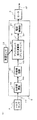
- FIG. 18 is a block diagram showing the configuration of the control device in the electric power steering apparatus according to Embodiment 5 of the present invention.
- the difference between the electric power steering apparatus according to Embodiment 5 of the present invention and the case of Embodiment 4 described above is that, in the case of Embodiment 5 of the present invention, the motor speed compensation output from the motor speed compensator 52 is as follows.
- the subtractor 29 for subtracting the motor speed correction signal Tvc from the unit 52 from the assist torque command signal Ia is provided, and the other portions are the same as in the fourth embodiment. In the following description, the difference will be mainly described.
- the motor speed correction signal Tvc is subtracted from the assist torque command signal Ia in the subtractor 29 to become a corrected assist torque command signal, that is, a motor current command signal Iref.
- the configuration of the motor speed compensation unit 52 is the same as that of the fourth embodiment, and only the set value of the gain 63 is different.
- the motor speed correction signal Tvc does not pass through the assist torque command calculation unit 20 and has no amplification effect due to the assist gradient. Therefore, the gain 63 is larger than that of the fourth embodiment. Set. Thereby, the same phase advance effect can be obtained even when the assist gradient is large.
- the motor speed correction signal Tvc obtained by correcting the motor speed signal ⁇ m from the motor speed detection unit 51 that detects the rotation speed of the rotation shaft of the motor is used as an assist torque command. Since it is configured to negatively feed back to the signal Ia, the phase delay compensation characteristic from the post-compensation steering torque signal Tsca to the assist torque command signal Ia realized by the high frequency compensation unit 22, and the motor speed correction signal obtained by correcting the motor speed signal Since phase lag lead compensation can be configured by combining the phase lead characteristics due to the negative feedback of Tvc, the stability can be improved by lowering the gain crossover frequency and improving the phase margin. An effect can be obtained. Further, even when the assist gradient is near zero, the phase advance effect by the motor speed correction signal can be expected, so that the disturbance suppression and the stabilization effect can be improved.
- the present invention is not limited to the electric power steering device according to the first to fifth embodiments described above, and the configurations of the first to fifth embodiments are within the scope of the present invention. Can be appropriately combined, a part of the configuration can be modified, or a part of the configuration can be omitted.
- the electric power steering apparatus according to the present invention can be applied to a steering system of a vehicle such as an automobile, and can be used in the automobile industry.
Landscapes
- Engineering & Computer Science (AREA)
- Chemical & Material Sciences (AREA)
- Combustion & Propulsion (AREA)
- Transportation (AREA)
- Mechanical Engineering (AREA)
- Steering Control In Accordance With Driving Conditions (AREA)
- Power Steering Mechanism (AREA)
Abstract
La présente invention concerne un dispositif de direction assistée électrique qui comprend une unité de compensation à haute fréquence qui émet un signal de compensation à haute fréquence obtenu en filtrant une composante à haute fréquence à partir d'un signal de commande de couple d'assistance et en multipliant un gain. Un signal de couple de direction corrigé, obtenu en renvoyant le signal de compensation à haute fréquence sous forme de rétroaction négative ou de rétroaction positive à un signal de couple de direction, est entré dans une unité de calcul de commande de couple d'assistance, et l'unité de calcul de commande de couple d'assistance émet un signal de commande de couple d'assistance en réponse au signal de couple de direction corrigé.
Priority Applications (5)
| Application Number | Priority Date | Filing Date | Title |
|---|---|---|---|
| EP16903077.2A EP3466797B1 (fr) | 2016-05-24 | 2016-05-24 | Dispositif de direction assistée électrique |
| CN201680085789.2A CN109153408B (zh) | 2016-05-24 | 2016-05-24 | 电动助力转向装置 |
| JP2018518840A JP6584658B2 (ja) | 2016-05-24 | 2016-05-24 | 電動パワーステアリング装置 |
| US16/085,683 US11338844B2 (en) | 2016-05-24 | 2016-05-24 | Electric power steering apparatus |
| PCT/JP2016/065287 WO2017203595A1 (fr) | 2016-05-24 | 2016-05-24 | Dispositif de direction assistée électrique |
Applications Claiming Priority (1)
| Application Number | Priority Date | Filing Date | Title |
|---|---|---|---|
| PCT/JP2016/065287 WO2017203595A1 (fr) | 2016-05-24 | 2016-05-24 | Dispositif de direction assistée électrique |
Publications (1)
| Publication Number | Publication Date |
|---|---|
| WO2017203595A1 true WO2017203595A1 (fr) | 2017-11-30 |
Family
ID=60411679
Family Applications (1)
| Application Number | Title | Priority Date | Filing Date |
|---|---|---|---|
| PCT/JP2016/065287 Ceased WO2017203595A1 (fr) | 2016-05-24 | 2016-05-24 | Dispositif de direction assistée électrique |
Country Status (5)
| Country | Link |
|---|---|
| US (1) | US11338844B2 (fr) |
| EP (1) | EP3466797B1 (fr) |
| JP (1) | JP6584658B2 (fr) |
| CN (1) | CN109153408B (fr) |
| WO (1) | WO2017203595A1 (fr) |
Cited By (1)
| Publication number | Priority date | Publication date | Assignee | Title |
|---|---|---|---|---|
| JP2020075564A (ja) * | 2018-11-06 | 2020-05-21 | 株式会社デンソー | ステアリング制御装置 |
Families Citing this family (12)
| Publication number | Priority date | Publication date | Assignee | Title |
|---|---|---|---|---|
| US11338844B2 (en) * | 2016-05-24 | 2022-05-24 | Mitsubishi Electric Cornoration | Electric power steering apparatus |
| CN110072761B (zh) * | 2016-12-12 | 2022-03-04 | 福特汽车公司 | 防振型驾驶员辅助装置 |
| JP7342738B2 (ja) * | 2020-03-09 | 2023-09-12 | ニデック株式会社 | 電動パワーステアリング装置に用いられる制御装置、制御方法、およびモータモジュール |
| CN113581277B (zh) * | 2020-04-30 | 2022-09-06 | 豫北转向系统(新乡)有限公司 | 一种用于eps的抑制转向力矩波动的方法及系统 |
| US11459026B2 (en) * | 2020-05-21 | 2022-10-04 | Robert Bosch Gmbh | Backup control of electric power steering system when sensor failure occurs |
| JP7491785B2 (ja) * | 2020-09-07 | 2024-05-28 | 株式会社ジェイテクト | 操舵制御装置 |
| JP7470621B2 (ja) * | 2020-11-16 | 2024-04-18 | 株式会社Soken | 回転角度検出装置 |
| US11975777B2 (en) * | 2021-04-02 | 2024-05-07 | Steering Solutions Ip Holding Corporation | Systems and methods for over learning protection for torque steer mitigation |
| US12172706B2 (en) * | 2021-09-29 | 2024-12-24 | Nidec Corporation | Motor control device, motor control method, motor module, and electric power steering device |
| WO2023112944A1 (fr) * | 2021-12-16 | 2023-06-22 | ニデック株式会社 | Dispositif de commande et système de maintien de voie |
| CN115158442B (zh) * | 2022-08-16 | 2024-05-17 | 中国第一汽车股份有限公司 | 助力力矩的确定方法、装置、存储介质及处理器 |
| CN119218294A (zh) * | 2023-06-29 | 2024-12-31 | 尼得科株式会社 | 控制装置和转向装置 |
Citations (4)
| Publication number | Priority date | Publication date | Assignee | Title |
|---|---|---|---|---|
| JP2002029433A (ja) * | 2000-07-19 | 2002-01-29 | Mitsubishi Electric Corp | 電動式パワーステアリング装置 |
| JP2006335228A (ja) * | 2005-06-02 | 2006-12-14 | Mitsubishi Electric Corp | 電動パワーステアリング制御装置 |
| JP2010058601A (ja) * | 2008-09-02 | 2010-03-18 | Kayaba Ind Co Ltd | 電動パワーステアリングの制御装置 |
| WO2012160850A1 (fr) * | 2011-05-25 | 2012-11-29 | 三菱電機株式会社 | Dispositif de commande de direction à alimentation électrique |
Family Cites Families (23)
| Publication number | Priority date | Publication date | Assignee | Title |
|---|---|---|---|---|
| US5473231A (en) | 1994-05-11 | 1995-12-05 | Trw Inc. | Method and apparatus for controlling an electric assist steering system using an adaptive torque filter |
| US6107767A (en) * | 1998-03-20 | 2000-08-22 | Trw Inc. | Electric assist steering system having an improved motor current controller with notch filter |
| GB0401965D0 (en) * | 2004-01-30 | 2004-03-03 | Trw Lucasvarity Electric Steer | Method and apparatus for controlling an electric assist motor using a modified blending filter |
| EP1837266B1 (fr) * | 2005-01-14 | 2012-03-14 | Nsk Ltd. | Controleur de dispositif de direction a assistance electrique |
| CN201058621Y (zh) * | 2007-06-01 | 2008-05-14 | 天津亿普斯电子科技有限公司 | 一种电动助力转向电子控制器 |
| CN101821150B (zh) * | 2007-12-14 | 2013-03-06 | 三菱电机株式会社 | 电动动力转向控制装置 |
| JP5235536B2 (ja) * | 2008-07-03 | 2013-07-10 | 三菱電機株式会社 | 電動パワーステアリング制御装置 |
| CN103448794B (zh) * | 2009-09-28 | 2016-06-22 | 日本精工株式会社 | 电动动力转向装置 |
| JP6032161B2 (ja) * | 2013-09-04 | 2016-11-24 | トヨタ自動車株式会社 | 操舵装置、及び、操舵制御装置 |
| CN105083370B (zh) * | 2014-05-09 | 2018-01-16 | 现代摩比斯株式会社 | Mdps的补偿控制装置 |
| DE112015003513T5 (de) * | 2014-07-31 | 2017-07-06 | Trw Automotive U.S. Llc | Unterstützungskompensation für aktiv gesteuerte Servolenkungssysteme |
| US10099721B2 (en) * | 2014-11-19 | 2018-10-16 | Nsk Ltd. | Electric power steering apparatus |
| CN104590362A (zh) * | 2014-12-01 | 2015-05-06 | 中国第一汽车股份有限公司 | 基于交流异步电机的电动助力转向系统控制装置及控制器 |
| US20170072994A1 (en) * | 2015-09-14 | 2017-03-16 | Mando Corporation | Apparatus and method for controlling electric power steering system |
| KR102389093B1 (ko) * | 2015-12-10 | 2022-04-21 | 주식회사 만도 | 조향 제어 장치 및 조향 제어 방법 |
| KR102341111B1 (ko) * | 2015-12-14 | 2021-12-21 | 현대모비스 주식회사 | 전동식 조향 장치 및 그 제어 방법 |
| KR102322485B1 (ko) * | 2015-12-29 | 2021-11-09 | 주식회사 만도 | 조향 제어 장치 및 조향 제어 방법 |
| WO2017150445A1 (fr) * | 2016-02-29 | 2017-09-08 | 日本精工株式会社 | Appareil de direction à assistance électrique |
| CN108778903B (zh) * | 2016-03-25 | 2021-06-04 | 日本精工株式会社 | 电动助力转向装置 |
| US11338844B2 (en) * | 2016-05-24 | 2022-05-24 | Mitsubishi Electric Cornoration | Electric power steering apparatus |
| WO2017213130A1 (fr) * | 2016-06-06 | 2017-12-14 | 日本精工株式会社 | Dispositif de direction assistée électrique |
| US10435062B2 (en) * | 2017-06-29 | 2019-10-08 | Steering Solutions Ip Holding Corporation | Electric power steering system with uniform architecture for multiple operating modes |
| KR102224996B1 (ko) * | 2017-06-30 | 2021-03-10 | 현대모비스 주식회사 | 전동식 파워 스티어링 시스템의 토크 보상 장치 및 방법 |
-
2016
- 2016-05-24 US US16/085,683 patent/US11338844B2/en active Active
- 2016-05-24 WO PCT/JP2016/065287 patent/WO2017203595A1/fr not_active Ceased
- 2016-05-24 CN CN201680085789.2A patent/CN109153408B/zh active Active
- 2016-05-24 EP EP16903077.2A patent/EP3466797B1/fr active Active
- 2016-05-24 JP JP2018518840A patent/JP6584658B2/ja active Active
Patent Citations (4)
| Publication number | Priority date | Publication date | Assignee | Title |
|---|---|---|---|---|
| JP2002029433A (ja) * | 2000-07-19 | 2002-01-29 | Mitsubishi Electric Corp | 電動式パワーステアリング装置 |
| JP2006335228A (ja) * | 2005-06-02 | 2006-12-14 | Mitsubishi Electric Corp | 電動パワーステアリング制御装置 |
| JP2010058601A (ja) * | 2008-09-02 | 2010-03-18 | Kayaba Ind Co Ltd | 電動パワーステアリングの制御装置 |
| WO2012160850A1 (fr) * | 2011-05-25 | 2012-11-29 | 三菱電機株式会社 | Dispositif de commande de direction à alimentation électrique |
Cited By (2)
| Publication number | Priority date | Publication date | Assignee | Title |
|---|---|---|---|---|
| JP2020075564A (ja) * | 2018-11-06 | 2020-05-21 | 株式会社デンソー | ステアリング制御装置 |
| JP7139895B2 (ja) | 2018-11-06 | 2022-09-21 | 株式会社デンソー | ステアリング制御装置 |
Also Published As
| Publication number | Publication date |
|---|---|
| US20190100234A1 (en) | 2019-04-04 |
| JP6584658B2 (ja) | 2019-10-02 |
| US11338844B2 (en) | 2022-05-24 |
| EP3466797A4 (fr) | 2019-06-19 |
| EP3466797B1 (fr) | 2020-08-19 |
| EP3466797A1 (fr) | 2019-04-10 |
| JPWO2017203595A1 (ja) | 2018-12-13 |
| CN109153408B (zh) | 2020-07-24 |
| CN109153408A (zh) | 2019-01-04 |
Similar Documents
| Publication | Publication Date | Title |
|---|---|---|
| JP6584658B2 (ja) | 電動パワーステアリング装置 | |
| CN103562049B (zh) | 电动助力转向的控制装置 | |
| EP3199426B1 (fr) | Dispositif de direction assistée électrique | |
| US9335228B2 (en) | Dynamometer system control device | |
| CN107921999B (zh) | 电动助力转向装置的控制装置 | |
| US10000235B2 (en) | Steering control device | |
| WO2011052470A1 (fr) | Dispositif de commande de direction assistée électrique | |
| JPWO2012073760A1 (ja) | 電動パワーステアリング装置 | |
| US11364948B2 (en) | Electric power steering device | |
| WO2020145036A1 (fr) | Dispositif de direction de véhicule | |
| JP6705314B2 (ja) | ステアリング制御装置 | |
| WO2020217550A1 (fr) | Dispositif de direction de véhicule | |
| WO2016163343A1 (fr) | Dispositif de commande de moteur et dispositif de direction assistée électrique le comportant |
Legal Events
| Date | Code | Title | Description |
|---|---|---|---|
| WWE | Wipo information: entry into national phase |
Ref document number: 2018518840 Country of ref document: JP |
|
| NENP | Non-entry into the national phase |
Ref country code: DE |
|
| 121 | Ep: the epo has been informed by wipo that ep was designated in this application |
Ref document number: 16903077 Country of ref document: EP Kind code of ref document: A1 |
|
| ENP | Entry into the national phase |
Ref document number: 2016903077 Country of ref document: EP Effective date: 20190102 |