WO2017203699A1 - Dispositif de support de rail de guidage et procédé de support de rail de guidage - Google Patents
Dispositif de support de rail de guidage et procédé de support de rail de guidage Download PDFInfo
- Publication number
- WO2017203699A1 WO2017203699A1 PCT/JP2016/065746 JP2016065746W WO2017203699A1 WO 2017203699 A1 WO2017203699 A1 WO 2017203699A1 JP 2016065746 W JP2016065746 W JP 2016065746W WO 2017203699 A1 WO2017203699 A1 WO 2017203699A1
- Authority
- WO
- WIPO (PCT)
- Prior art keywords
- guide rail
- rail
- joint plate
- backing
- pressing
- Prior art date
- Legal status (The legal status is an assumption and is not a legal conclusion. Google has not performed a legal analysis and makes no representation as to the accuracy of the status listed.)
- Ceased
Links
Images



Classifications
-
- B—PERFORMING OPERATIONS; TRANSPORTING
- B66—HOISTING; LIFTING; HAULING
- B66B—ELEVATORS; ESCALATORS OR MOVING WALKWAYS
- B66B7/00—Other common features of elevators
- B66B7/02—Guideways; Guides
Definitions
- the present invention relates to a guide rail support device and a guide rail support method for supporting a guide rail that guides the vertical movement of an elevator car.
- the guide rail provided in the elevator hoistway guides the elevator car vertically moving, and a plurality of rail members are connected in the vertical direction via a joint plate.
- a joint plate In modernization such as seismic reinforcement of elevator equipment, that is, at the time of repair or maintenance, it may be necessary to replace the seam plate.
- it is necessary to temporarily support the guide rail so that the positions of the rail members do not shift and to maintain the positions of the upper and lower rail members.
- the upper and lower rail members can be centered by being fixed to the flange of the guide rail at the time of connecting the guide rail, and supporting the side portion of the flange of the guide rail by pressing with a jack bolt.
- a possible guide rail centering device is described.
- This invention is made in order to solve such a problem, and the guide rail support apparatus and guide rail support method which can support a guide rail temporarily so that the joint plate of a guide rail can be replaced
- the purpose is to provide.
- a guide rail support device guides the movement of an elevator car in the vertical direction, and includes a plurality of rail members that are respectively connected in the vertical direction via a joint plate.
- a rail backing that supports the guide rail and is fixed over at least two rail members that are connected in the vertical direction and that does not overlap the joint plate, and presses the guide rail against the rail backing
- a pressing portion and a clamping portion that sandwiches the guide rail from both sides in a direction different from the pressing direction in which the guide rail is pressed by the pressing portion.
- the guide rail of the guide rail support device has a flange portion to which the joint plate is fixed, and a convex head portion that protrudes from the flange portion and guides the vertical movement of the elevator.
- the backing may be fixed to the flange portion, the pressing portion may press the convex head in the pressing direction, and the holding portion may sandwich both side surfaces of the convex head in the vertical direction and in the direction perpendicular to the pressing direction.
- the rail backing, the pressing part, and the clamping part may be connected by a jumper member.
- the rail backing is formed with an opening through which the joint plate is exposed when fixed to the guide rail, and the size of the opening may be larger than the outer shape of the joint plate.
- the guide rail support device guides the movement of the elevator car in the vertical direction, and supports the guide rail having a plurality of rail members each connected in the vertical direction via the joint plate.
- a rail support method wherein the rail backing is fixed so as not to overlap the joint plate over at least two rail members connected in the vertical direction, the guide rail is pressed against the rail backing, and the guide rail Is gripped by sandwiching the guide rail from both sides in a direction different from the pressing direction pressed by the pressing portion.
- the guide rail can be temporarily supported so that the joint plate of the guide rail can be easily replaced.
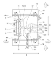
- FIG. 3 is a cross-sectional view showing a state in which the guide rail support device shown in FIG. 1 is cut along a cutting line III-III shown in FIGS.
- FIG. 3 is a cross-sectional view showing a state in which the guide rail support device shown in FIG. 1 is cut along a cutting line III-III shown in FIGS.
- FIG. 3 is a cross-sectional view showing a state in which the guide rail support device shown in FIG. 1 is cut along a cutting line III-III shown in FIGS.
- FIG. 3 is a cross-sectional view showing a state in which the guide rail support device shown in FIG. 1 is cut along a cutting line III-III shown in FIGS.
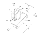
- FIG. 1 is a perspective view which shows the structure of the plate, the fixed shoe, and the movable shoe which are provided in the collar member of the guide rail support device shown in FIG.
- It is a figure which shows the attachment procedure of the guide rail support apparatus shown in FIG. 1, and is a figure which shows the guide rail before
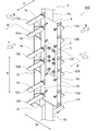
- FIG. 1 to 3 show a guide rail support device 100 for supporting a guide rail 5 for guiding the movement of an elevator car.
- the guide rail 5 has a plurality of rail members connected to each other.
- the guide rail support device 100 will be described as being attached to a connecting portion between the upper rail member 5a and the lower rail member 5b, which are a part of the plurality of rail members of the guide rail 5.
- a direction in which the guide rail 5 extends that is, a direction in which an elevator car (not shown) moves while being guided by the guide rail 5 is defined as a vertical direction H.
- the cross-sectional shape of the guide rail 5 is substantially T-shaped.
- the guide rail 5 includes a substantially plate-shaped flange portion 51 that extends in the vertical direction H, and a convex head portion 52 that protrudes along the center line of the flange portion 51 and extends in the vertical direction H.
- the convex head 52 is engaged with a guide mechanism (not shown) provided in the elevator car and guides the movement of the elevator car along the vertical direction H.
- the guide rail 5 is provided with a joint plate 3 for connecting the upper rail member 5a and the lower rail member 5b connected in the vertical direction H, fixed by eight fastening members 4 (see FIG. 5).
- a direction perpendicular to the vertical direction H and along the width of the flange portion 51 is defined as a width direction W.
- a direction in which the convex head 52 projects from the flange portion 51 is a depth direction D.
- the vertical direction H, the width direction W, and the depth direction D are orthogonal to each other.
- the side from which the convex head 52 protrudes is referred to as a front side F
- the side where the flange portion 51 faces is referred to as a back side B.
- the right side when viewed from the front side F is the right side R
- the left side when viewed from the front side F is the left side L.
- the edge part of the front side F of the convex head part 52 of the guide rail 5 be the front edge part 52a.
- the right side surface of the convex head 52 is a right side surface 52b
- the left side surface is a left side surface 52c.
- a substantially plate-shaped rail backing 6 is fixed to the back side B of the flange portion 51 of the guide rail 5 via eight rail clips 8.
- the rail backing 6 is fixed to the guide rail 5 by sandwiching the flange portion 51 of the guide rail 5 between the rail backing 6 and the rail clip 8.
- the rail backing 6 is attached over both the upper rail member 5a and the lower rail member 5b of the guide rail 5.
- an opening 6 a is formed in the rail backing 6, and when the rail backing 6 is fixed to the guide rail 5, the joint plate 3 is exposed to the back side B through the opening 6 a.
- the rail backing 6 is provided so as not to overlap the joint plate 3.
- the opening 6 a of the rail backing 6 is larger than the outer shape of the joint plate 3.
- the rail backing 6 has a pair of rising portions 6b that are formed with both end portions rising to the back side B.
- the six jumper beams 12a to 12f extending to the front side F are sequentially connected from the upper end to the lower end of the rail backing 6 to each of the rising portions 6b at both ends of the rail backing 6, and are fixed by bolt fastening.
- there are two jumper beams 12a to 12f from the top that is, the first, second and third jumper beams 12a and 12b from the top, and the fifth and sixth jumper beams 12c and 12d.
- the beams 12e and 12f are paired with each other.
- the positions of the third and fourth jumper beams 12c and 12d from the top are the attachment positions of the joint plate 3, that is, the connecting positions between the upper rail member 5a and the lower rail member 5b in the vertical direction.
- a jack bolt 19 is attached to each of the left L-shaped jumper beams 12a to 12f.
- the columnar pillars 11 extending in the vertical direction H are attached to the end portions on the front side F of the left and right collar beam 12a to 12f by bolt fastening.
- positioned at the right-and-left both sides seeing from the front side F has comprised the substantially L shape facing each other.
- three plates 16 are fixed between the pair of jumper pillars 11 by bolt fastening. In the up-and-down direction H, the three plates 16 are between the first and second jumper beams 12a and 12b from the top, between the third and fourth jumper beams 12c and 12d, and the fifth and sixth jumper beams. 12e and 12f are arranged respectively.
- the jumper column 11 and the jumper beams 12 a to 12 f constitute the jumper member 10.
- each of the three plates 16 has a first slit 16a cut out in a substantially rectangular shape from the end on the back side B toward the front side F in the depth direction D. Is formed. Further, the plate 16 is formed with a second slit 16b that is cut out in a substantially square shape adjacent to the left side L of the first slit 16a.
- a fixed shoe 14 having a substantially L-shaped cross section is fixed and attached to the right side R of the first slit 16 a of the plate 16.
- the portion of the fixed shoe 14 that faces the front side F constitutes a pressing portion 14a, is connected to the right side R of the pressing portion 14a, and extends to the back side B in the depth direction D.
- the portion constitutes a side contact portion 14b.
- the pressing portion 14 a of the fixed shoe 14 presses the convex head 52 against the rail backing 6. Further, the side contact portion 14 b of the fixed shoe 14 contacts the right side surface 52 b of the convex head 52.
- a direction in which the pressing portion 14a of the fixed shoe 14 presses the convex head 52 is defined as a pressing direction. The pressing direction coincides with the depth direction D.
- the substantially rectangular parallelepiped movable shoe 15 is engaged with the second slit 16 b of the plate 16.
- the movable shoe 15 can move in the width direction W along the second slit 16b.
- the end portion of the jack bolt 19 attached to each of the left L-shaped jumper beams 12 a to 12 f comes into contact with the movable shoe 15. Therefore, by moving the jack bolt 19 to the right R and pushing it in, the movable shoe 15 also moves to the right R and comes into contact with the left side surface 52c of the convex head 52. That is, in the width direction W, the movable shoe 15 can sandwich the both side surfaces 52 b and 52 c of the convex head portion 52 with the side surface contact portion 14 b of the fixed shoe 14.
- the fixed shoe 14 and the movable shoe 15 provided on the plate 16 are connected to the rail backing 6 via the jumper member 10. Further, the side contact portion 14b and the movable shoe 15 of the fixed shoe 14 constitute a clamping portion.
- FIGS. 5 a procedure for attaching the guide rail support device 100 to the guide rail 5 and removing the joint plate 3 will be described with reference to FIGS. These operations are performed at such a height that a worker on the work surface on the elevator car can work sufficiently.
- the upper rail member 5 a and the lower rail member 5 b of the guide rail 5 are attached to the back side B of the flange portion 51 in a state where the guide rail support device 100 is not attached. They are connected by a joint plate 3.
- the rail backing 6 is attached to the back side B of the flange portion 51 via the rail clip 8 across the upper rail member 5 a and the lower rail member 5 b.
- the rail backing 6 is arranged so that the position of the opening 6 a coincides with the joint plate 3.
- the jumper members 10 projecting to the front side F are connected to the rising portions 6 b at both ends of the rail backing 6.
- the nut 4a of the fastening member 4 fixing the joint plate 3 to the guide rail 5 is removed from the bolt 4b. Then, the joint plate 3 is removed through the opening 6 a of the rail backing 6. After the joint plate 3 is removed, a new joint plate 3 is fitted into the position of the opening 6 a of the rail backing 6 and is fixed again by the fastening member 4. And the guide rail support apparatus 100 is removed from the guide rail 5 in the reverse procedure to attachment.
- the rail backing 6 provided so as not to overlap the joint plate 3 is fixed across the upper rail member 5a and the lower rail member 5b.
- the pressing portion 14 a of the fixed shoe 14 presses the convex head 52 of the guide rail 5 in the depth direction D against the rail backing 6.
- the side contact portion 14b of the fixed shoe 14 and the movable shoe 15 support the both side surfaces of the convex head 52 sandwiched therebetween.
- the upper rail member 5a and the lower rail member 5b of the guide rail 5 are firmly supported from both the depth direction D and the width direction W, that is, from two different directions.
- the positions of the member 5a and the lower rail member 5b are not shifted. Therefore, the worker can easily and easily replace the joint plate 3 on the elevator car in a state where a load is applied to the guide rail 5.
- exchange of a joint board becomes easy.
- the fixed shoe 14 and the movable shoe 15 provided on the plate 16 are connected to the rail backing 6 via the jumper member 10. Accordingly, the guide rail support device 100 simultaneously connects the rear side B of the flange portion 51 of the guide rail 5, the front end 52 a of the front side F of the convex head 52, and both side surfaces 52 b and 52 c of the convex head 52. Can be supported. Therefore, the guide rail support device 100 can support the guide rail 5 more firmly.
- the rail backing 6 has an opening 6a for attaching and detaching the joint plate 3. The opening 6a is larger than the outer shape of the joint plate 3, so that the replacement operation of the joint plate 3 can be performed more smoothly. it can.
- the rail backing 6 is fixed so as not to overlap the joint plate 3 over the upper rail member 5a and the lower rail member 5b. Then, the guide rail 5 is pressed against the rail backing 6 in the depth direction D and sandwiched from both sides in the width direction W. Thereby, since the guide rail 5 is supported from the depth direction D and the width direction W, that is, two different directions, it can be supported more firmly than the case where it is supported from only one direction. Therefore, even if the joint plate 3 is removed, the positions of the upper rail member 5a and the lower rail member 5b are not displaced, and the replacement operation of the joint plate 3 can be easily performed in a short time.
- the guide rail support device 100 supports the upper rail member 5a and the lower rail member 5b connected in the vertical direction H.
- the present invention is not limited to this, and three or more guide rail support devices 100 are supported. It may be attached and supported across the rail member.
- the guide rail support device 100 is provided with three plates 16 along the vertical direction H.
- the plate rail support device 100 is not limited to this, and the guide rail support device 100 has 5 to 7 steps depending on the load acting on the guide rail 5. It may be increased.
- the press part 14a and the side contact part 14b of the fixed shoe 14 are integrally formed, it is not limited to this, The press part 14a and the side contact part 14b may be provided separately.
Landscapes
- Lift-Guide Devices, And Elevator Ropes And Cables (AREA)
Abstract
L'objectif de l'invention est de fournir un dispositif de support de rail de guidage et un procédé de support de rail de guidage avec lesquels il est possible de supporter temporairement un rail de guidage de sorte qu'une plaque de jonction du rail de guidage puisse être remplacée facilement. Un dispositif de support de rail de guidage supporte un rail de guidage qui comporte des éléments de rail reliés dans la direction verticale, et le dispositif de support de rail de guidage comprend : un appui de rail qui s'étend en travers et qui est fixé aux éléments de rail et qui est disposé de façon à ne pas chevaucher une plaque de jonction ; une unité de pression de sabot fixe qui presse le rail de guidage contre l'appui de rail ; et une partie contact de face latérale de sabot fixe et un sabot mobile qui prennent en sandwich le rail de guidage des deux côtés dans la direction de la largeur, qui est une direction différente de la direction de la profondeur qui est la direction dans laquelle le rail de guidage est pressé.
Priority Applications (2)
| Application Number | Priority Date | Filing Date | Title |
|---|---|---|---|
| PCT/JP2016/065746 WO2017203699A1 (fr) | 2016-05-27 | 2016-05-27 | Dispositif de support de rail de guidage et procédé de support de rail de guidage |
| TW105132047A TWI635037B (zh) | 2016-05-27 | 2016-10-04 | 導軌支持裝置及導軌支持方法 |
Applications Claiming Priority (1)
| Application Number | Priority Date | Filing Date | Title |
|---|---|---|---|
| PCT/JP2016/065746 WO2017203699A1 (fr) | 2016-05-27 | 2016-05-27 | Dispositif de support de rail de guidage et procédé de support de rail de guidage |
Publications (1)
| Publication Number | Publication Date |
|---|---|
| WO2017203699A1 true WO2017203699A1 (fr) | 2017-11-30 |
Family
ID=60412183
Family Applications (1)
| Application Number | Title | Priority Date | Filing Date |
|---|---|---|---|
| PCT/JP2016/065746 Ceased WO2017203699A1 (fr) | 2016-05-27 | 2016-05-27 | Dispositif de support de rail de guidage et procédé de support de rail de guidage |
Country Status (2)
| Country | Link |
|---|---|
| TW (1) | TWI635037B (fr) |
| WO (1) | WO2017203699A1 (fr) |
Cited By (3)
| Publication number | Priority date | Publication date | Assignee | Title |
|---|---|---|---|---|
| WO2020261804A1 (fr) * | 2019-06-24 | 2020-12-30 | 株式会社日立ビルシステム | Procédé de pose de rails de guidage et gabarit de prévention de rotation |
| WO2023053361A1 (fr) * | 2021-09-30 | 2023-04-06 | 三菱電機株式会社 | Dispositif de rail de guidage d'ascenseur et son procédé d'installation |
| JP7338771B1 (ja) | 2022-11-02 | 2023-09-05 | フジテック株式会社 | ガイドレール把持装置 |
Citations (3)
| Publication number | Priority date | Publication date | Assignee | Title |
|---|---|---|---|---|
| JPS5437676U (fr) * | 1977-08-18 | 1979-03-12 | ||
| JPS60151875U (ja) * | 1984-03-22 | 1985-10-09 | 三菱電機株式会社 | エレベ−タ用ガイドレ−ルの芯出し装置 |
| JP2003002555A (ja) * | 2001-06-18 | 2003-01-08 | Mitsubishi Electric Corp | エレベータのレール芯出し装置 |
Family Cites Families (2)
| Publication number | Priority date | Publication date | Assignee | Title |
|---|---|---|---|---|
| JPS5913707Y2 (ja) * | 1978-01-24 | 1984-04-23 | 株式会社東海理化電機製作所 | 自動復帰型プッシュスイッチ |
| SG124253A1 (en) * | 1998-07-13 | 2006-08-30 | Inventio Ag | Rope traction elevator |
-
2016
- 2016-05-27 WO PCT/JP2016/065746 patent/WO2017203699A1/fr not_active Ceased
- 2016-10-04 TW TW105132047A patent/TWI635037B/zh not_active IP Right Cessation
Patent Citations (3)
| Publication number | Priority date | Publication date | Assignee | Title |
|---|---|---|---|---|
| JPS5437676U (fr) * | 1977-08-18 | 1979-03-12 | ||
| JPS60151875U (ja) * | 1984-03-22 | 1985-10-09 | 三菱電機株式会社 | エレベ−タ用ガイドレ−ルの芯出し装置 |
| JP2003002555A (ja) * | 2001-06-18 | 2003-01-08 | Mitsubishi Electric Corp | エレベータのレール芯出し装置 |
Cited By (5)
| Publication number | Priority date | Publication date | Assignee | Title |
|---|---|---|---|---|
| WO2020261804A1 (fr) * | 2019-06-24 | 2020-12-30 | 株式会社日立ビルシステム | Procédé de pose de rails de guidage et gabarit de prévention de rotation |
| WO2023053361A1 (fr) * | 2021-09-30 | 2023-04-06 | 三菱電機株式会社 | Dispositif de rail de guidage d'ascenseur et son procédé d'installation |
| JP7614385B2 (ja) | 2021-09-30 | 2025-01-15 | 三菱電機株式会社 | エレベーターのガイドレール装置及びその据付方法 |
| JP7338771B1 (ja) | 2022-11-02 | 2023-09-05 | フジテック株式会社 | ガイドレール把持装置 |
| JP2024066730A (ja) * | 2022-11-02 | 2024-05-16 | フジテック株式会社 | ガイドレール把持装置 |
Also Published As
| Publication number | Publication date |
|---|---|
| TWI635037B (zh) | 2018-09-11 |
| TW201741223A (zh) | 2017-12-01 |
Similar Documents
| Publication | Publication Date | Title |
|---|---|---|
| KR101331424B1 (ko) | 레이저 용접용 지그 장치 | |
| KR20150137354A (ko) | 레이저 가공장치 | |
| CN110125600B (zh) | 焊接定位架及具有其工装 | |
| KR20110065865A (ko) | 범퍼빔용 클램핑 장치 | |
| JP2014019044A (ja) | 脆性材料基板のブレイク装置 | |
| JP2004243394A (ja) | 溶接用治具 | |
| CN105934290A (zh) | 压弯机 | |
| CN106002034B (zh) | 适于吊重行驶轮式起重机前车架中部支撑总成的搭焊工装 | |
| TWI635037B (zh) | 導軌支持裝置及導軌支持方法 | |
| JP6085384B2 (ja) | 脆性材料基板のブレイク装置 | |
| JP5234277B2 (ja) | 走行ガイド付き載物台 | |
| WO2014103392A1 (fr) | Dispositif de support de plaque de plateforme et procédé de construction de dalle l'utilisant | |
| JP6726597B2 (ja) | レーザ加工機 | |
| JP2011144014A (ja) | エレベータの組立治具 | |
| JP7569768B2 (ja) | 柱の溶接方法、及び、溶接機械設置装置 | |
| JP2008068961A (ja) | エレベータ用ガイドレールの継目板 | |
| JP3169966U (ja) | 調整式ガラス板加工挟持構造 | |
| JP2018119306A (ja) | 根太受け金物、床構造、及び床構造の施工方法 | |
| JP7090049B2 (ja) | 位置決め治具 | |
| KR200468675Y1 (ko) | 조절이 가능한 유리판 가공 클램프의 개선된 구조 | |
| KR101732377B1 (ko) | 파이프 지지용 지그 및 이를 포함하는 파이프 조립체 지지 장치 | |
| CN105089271A (zh) | 机械式预埋螺栓定位安装组件 | |
| KR20130058928A (ko) | H형 빌트업 형강재 취부방법 | |
| KR20240176720A (ko) | 프로파일 가공장치 | |
| KR20150001034U (ko) | 선체블록의 용접작업 가이드장치 |
Legal Events
| Date | Code | Title | Description |
|---|---|---|---|
| 121 | Ep: the epo has been informed by wipo that ep was designated in this application |
Ref document number: 16903180 Country of ref document: EP Kind code of ref document: A1 |
|
| NENP | Non-entry into the national phase |
Ref country code: DE |
|
| 122 | Ep: pct application non-entry in european phase |
Ref document number: 16903180 Country of ref document: EP Kind code of ref document: A1 |
|
| NENP | Non-entry into the national phase |
Ref country code: JP |