WO2017203717A1 - Poudre métallique de moulage de pièces en stratifié, procédé de fabrication d'article à pièces en stratifié moulées, et article à pièces en stratifié moulées - Google Patents
Poudre métallique de moulage de pièces en stratifié, procédé de fabrication d'article à pièces en stratifié moulées, et article à pièces en stratifié moulées Download PDFInfo
- Publication number
- WO2017203717A1 WO2017203717A1 PCT/JP2016/065829 JP2016065829W WO2017203717A1 WO 2017203717 A1 WO2017203717 A1 WO 2017203717A1 JP 2016065829 W JP2016065829 W JP 2016065829W WO 2017203717 A1 WO2017203717 A1 WO 2017203717A1
- Authority
- WO
- WIPO (PCT)
- Prior art keywords
- metal powder
- silicon
- mass
- layered object
- magnesium
- Prior art date
- Legal status (The legal status is an assumption and is not a legal conclusion. Google has not performed a legal analysis and makes no representation as to the accuracy of the status listed.)
- Ceased
Links
Images


Classifications
-
- B—PERFORMING OPERATIONS; TRANSPORTING
- B22—CASTING; POWDER METALLURGY
- B22F—WORKING METALLIC POWDER; MANUFACTURE OF ARTICLES FROM METALLIC POWDER; MAKING METALLIC POWDER; APPARATUS OR DEVICES SPECIALLY ADAPTED FOR METALLIC POWDER
- B22F1/00—Metallic powder; Treatment of metallic powder, e.g. to facilitate working or to improve properties
-
- B—PERFORMING OPERATIONS; TRANSPORTING
- B22—CASTING; POWDER METALLURGY
- B22F—WORKING METALLIC POWDER; MANUFACTURE OF ARTICLES FROM METALLIC POWDER; MAKING METALLIC POWDER; APPARATUS OR DEVICES SPECIALLY ADAPTED FOR METALLIC POWDER
- B22F3/00—Manufacture of workpieces or articles from metallic powder characterised by the manner of compacting or sintering; Apparatus specially adapted therefor ; Presses and furnaces
- B22F3/10—Sintering only
- B22F3/105—Sintering only by using electric current other than for infrared radiant energy, laser radiation or plasma ; by ultrasonic bonding
-
- B—PERFORMING OPERATIONS; TRANSPORTING
- B22—CASTING; POWDER METALLURGY
- B22F—WORKING METALLIC POWDER; MANUFACTURE OF ARTICLES FROM METALLIC POWDER; MAKING METALLIC POWDER; APPARATUS OR DEVICES SPECIALLY ADAPTED FOR METALLIC POWDER
- B22F3/00—Manufacture of workpieces or articles from metallic powder characterised by the manner of compacting or sintering; Apparatus specially adapted therefor ; Presses and furnaces
- B22F3/12—Both compacting and sintering
- B22F3/16—Both compacting and sintering in successive or repeated steps
-
- C—CHEMISTRY; METALLURGY
- C22—METALLURGY; FERROUS OR NON-FERROUS ALLOYS; TREATMENT OF ALLOYS OR NON-FERROUS METALS
- C22C—ALLOYS
- C22C21/00—Alloys based on aluminium
- C22C21/02—Alloys based on aluminium with silicon as the next major constituent
Definitions
- the present invention relates to an additive manufacturing metal powder, a manufacturing method of an additive manufacturing object, and an additive manufacturing object.
- an additive manufacturing method for metal powder is known.
- the additive manufacturing method forms a metal powder layer in which metal powder is spread thinly, and irradiates a specific region of the metal powder layer with laser light based on slice data (drawing pattern) of a three-dimensional structure to be created.
- slice data drawing pattern
- the advantage of this additive manufacturing method is that it is possible to manufacture a shaped object having a complicated shape, which has been very difficult by machining such as cutting.
- Patent Document 1 discloses aluminum alloy powders containing bismuth in aluminum. A method of manufacturing a layered object using the method is disclosed.
- the maximum relative density of the manufactured additive manufacturing object is about 92%, and there is a problem in the denseness of the additive manufacturing object, which is applicable due to problems such as mechanical properties. Certain metal products may be subject to certain restrictions.
- the present invention has been made paying attention to the above-mentioned problems, for example, heat control parts such as heat exchangers and heat sinks, engine parts and suspension parts in the aerospace field and automobile field, various parts such as hydraulic parts, brackets, etc.
- heat control parts such as heat exchangers and heat sinks
- engine parts and suspension parts in the aerospace field and automobile field
- various parts such as hydraulic parts, brackets, etc.
- a metal powder for additive manufacturing capable of manufacturing an additive manufacturing object having high ductility and thermal conductivity in addition to a high relative density
- a manufacturing method of the additive manufacturing object and an additive laminate
- the object is to provide a model.
- the above object of the present invention is achieved by a metal powder for additive manufacturing containing aluminum as a main component and containing silicon and magnesium in a total amount of 10% by mass or less and having a silicon content of more than 1% by mass.
- the magnesium content in the metal powder includes 0% by mass.
- the total content of silicon and magnesium is 7% by mass or less.
- silicon is contained in an amount of 4% by mass or more.
- the metal powder according to the present invention is characterized by not containing magnesium.
- the above object of the present invention is to spread metal powder for additive manufacturing containing aluminum as a main component and containing silicon and magnesium in a total amount of 10% by mass or less and having a silicon content greater than 1% by mass.
- a first step of forming a metal powder layer, and a second step of shaping a block body by melting and solidifying a metal powder in a predetermined region of the metal powder layer, and the metal powder according to the first step It is also achieved by a manufacturing method of a layered object that manufactures a layered object in which a plurality of the block bodies are laminated and integrated by repeating layer formation and modeling of the block body in the second step.
- the magnesium content in the metal powder includes 0% by mass.
- the total content of silicon and magnesium is 7% by mass or less.
- silicon is contained in an amount of 4% by mass or more.
- magnesium is not contained.
- the metal powder in a predetermined region of the metal powder layer is irradiated with laser light, and the metal powder of the laser light irradiation part is formed into a block body. and which is characterized in that the energy density of the laser beam is not more than 30 J / mm 3 or more 140 J / mm 3. Energy density of the laser beam is preferably further 50 J / mm 3 or more 90 J / mm 3 or less.
- the above object of the present invention is comprised of a silicon-containing aluminum alloy containing aluminum as a main component and containing silicon and magnesium in total of 10% by mass or less and having a silicon content of more than 1% by mass.
- the block body is laminated and integrated, the relative density with respect to the theoretical density of the silicon-containing aluminum alloy is 97% or more, the thermal conductivity is 120 W / m ⁇ K or more, and the elongation at break is 13% or more. This is also achieved by a layered object.
- the magnesium content in the metal powder includes 0% by mass.
- the relative density of the silicon-containing aluminum alloy with respect to the theoretical density is 99% or more.
- the thermal conductivity is 140 W / m ⁇ K or more.
- the elongation at break is 15% or more.
- the silicon-containing aluminum alloy does not contain magnesium.
- the average particle diameter of the cells in a cross section perpendicular to the stacking direction of the block bodies is 1.0 ⁇ m or less.
- FIG. 4 is a process diagram illustrating a process of the method for manufacturing a layered object after FIG. 3.
- FIG. 5 is a process diagram illustrating a process of the manufacturing method of the layered object after FIG. 4.
- FIG. 7 is a process diagram illustrating a process of the method for manufacturing a layered object after FIG. 6.
- FIG. 8 is a process diagram illustrating a process of the method for manufacturing a layered object after FIG. 7.
- FIG. 9 is a process diagram illustrating a process of the method for manufacturing a layered object after FIG. 8. It is a top view of the test piece used for a tension test. It is explanatory drawing explaining the measuring method of the average particle diameter of a cell. It is a graph which shows the breaking elongation according to the silicon content of the layered product manufactured by the layered modeling using the Al—Si based alloy powder. It is a graph which shows the elongation at break according to the silicon content of the layered product manufactured by layered modeling using the Al—Si—Mg alloy powder.
- the present invention relates to an additive manufacturing technology capable of manufacturing a machine part having a complicated shape that is difficult to manufacture by machining or casting, for example, a heat control part such as a heat exchanger or a heat sink, aerospace field or automobile field. It can be widely applied to the production of various parts such as engine parts, suspension parts, hydraulic parts, brackets and the like.
- Thermal control parts require thermal conductivity in addition to mechanical strength as their performance, so when using layered objects for these applications, layered objects require high relative density and high thermal conductivity. To do.
- various parts of automobiles and aircraft require ductility to ensure reliability in addition to mechanical strength as a performance. Requires density and high elongation at break.
- the present inventor has examined an aluminum alloy powder that is lightweight and has good thermal conductivity as a metal powder for layered modeling. As a result, it was found that by performing additive manufacturing using an aluminum alloy powder having a specific composition, the manufactured additive manufactured product can achieve both mechanical strength, ductility, and thermal conductivity, resulting in the present invention. .
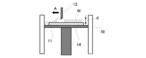
- FIG. 1 to FIG. 9 are process diagrams for explaining a process of a method for manufacturing a layered object 1 according to an embodiment of the present invention.
- the method of manufacturing the layered object 1 of the present embodiment includes a metal powder having a predetermined thickness obtained by spreading an aluminum alloy powder containing aluminum as a main component (hereinafter simply referred to as “metal powder”) on a base material 11, for example.
- a new metal By repeating the formation of the powder layer M and the modeling of the block body 2, the layered object 1 in which the plurality of block bodies 2 are laminated and integrated in the vertical direction is manufactured.
- the manufacturing apparatus for the layered object 1 includes, for example, a flat substrate 11 inside a chamber 10 surrounded by a metal powder, and metal powder is spread on the substrate 11.
- steel such as iron, aluminum, titanium, carbon steel / alloy steel / stainless steel
- general-purpose metal materials such as copper, or plastic materials having heat resistance such as ceramics, glass, polyimide, etc.
- a metal material having high bondability with the layered object 1 to be shaped such as aluminum, titanium, copper, iron, and steel, can be preferably used.
- a heating device (not shown) such as a heater is connected to the base material 11, and the base material 11 is constantly heated.
- the substrate 11 is constantly heated by the heating device, but it is not always necessary to heat the substrate 11 by the heating device.
- the surface of the base material 11 is preferably subjected to a surface roughening treatment by a known method such as a blast treatment in order to enhance the bondability with the layered object 1 to be shaped.
- a width plate-like squeegee 12 that can reciprocate horizontally in the chamber 10 is disposed above the base material 11.
- a metal powder supply unit (not shown) for storing the metal powder by sliding the squeegee 12 at a predetermined height above the surface of the base material 11.
- a flat metal powder layer (metal powder layer M) having a substantially constant overall thickness is formed on the substrate 11.
- the base material 11 is attached on the stage 14, and the vertical position of the base material 11 can be adjusted by the vertical movement of the stage 14. By adjusting the vertical position of the substrate 11, the thickness of the metal powder layer M can be changed as appropriate.
- the thickness of the metal powder layer M is preferably thinner in order to improve the dimensional accuracy of the layered object 1 to be manufactured.
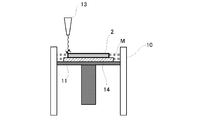
- the manufacturing apparatus includes a laser beam scanning device 13 that irradiates the metal powder layer M with laser light.
- the metal powder in the irradiated portion is heated and melted.
- the laser beam scanning device 13 includes a laser light source that emits a laser beam and an optical device such as a galvanometer mirror, and the laser beam is transmitted to an arbitrary region on the metal powder layer M by the galvanometer mirror or the like. In addition, scanning with a predetermined pattern shape is possible.
- the metal powder layer M can be selected and the metal powder can be locally heated by the laser beam. Therefore, only the metal powder in the irradiated portion of the laser beam is solidified to block the block 2 having a desired shape and size. Can be shaped.
- various lasers such as a fiber laser, a carbon dioxide gas laser, a YAG laser, and a semiconductor laser can be used.
- a powder bed fusion bonding method is used, and laser light is used as a means for solidifying the metal powder.
- an electron beam or plasma may be used.
- a 3D printing method additional manufacturing method
- a directional energy deposition method may be used.
- cutting or laser trimming may be performed during modeling, or surface modification with a laser or an electron beam may be performed during or after modeling.
- the manufacturing apparatus includes a gas tank that supplies atmospheric gas to the chamber 10 although not shown.
- a gas tank that supplies atmospheric gas to the chamber 10 although not shown.
- atmospheric gas nitrogen gas, argon gas, helium gas etc. can be illustrated, for example.
- a reducing gas may be used instead of the atmospheric gas.
- the inside of the chamber 10 may be decompressed by a vacuum pump or the like.
- the layered object 1 is manufactured using an aluminum alloy powder as the metal powder, and therefore the metal powder used will be described.
- Metal powder corresponds to toner and ink in a normal two-dimensional printer.
- the metal powder is an Al—Si alloy powder containing aluminum (Al) as a main component and silicon (Si) as a second component.
- the content of aluminum contained as a main component in the metal powder refers to, for example, 60% by mass or more, 70% by mass or more, or 80% by mass or more.
- the aluminum content in the metal powder can be measured by a method based on “JIS H 1305: Luminescence spectroscopic analysis method of aluminum and aluminum alloy”.
- the metal powder may contain other components in addition to aluminum and silicon.
- These components may be intentionally added during production, or may be inevitably mixed as impurities.
- Other components can preferably include magnesium.
- magnesium content in the metal powder is preferably 0.05% by mass or more and 1.5% by mass or less.
- the magnesium content in the metal powder can be measured by a method based on “JIS H 1307: Inductively coupled plasma emission spectroscopic analysis method of aluminum and aluminum alloy”.
- the upper limit of the silicon content in the metal powder is 10% by mass or less in total with magnesium, but is preferably 7% by mass or less. Moreover, it is preferable that the minimum of content of silicon is larger than 1 mass%, and is 4 mass% or more.
- the silicon content in the metal powder can be measured by a method based on “JIS H 1352: 2007: Method for quantifying silicon in aluminum and aluminum alloys”.
- magnesium can improve the intensity
- not containing magnesium in the metal powder means that it is not intentionally added to the metal powder, and is not excluded until it is inevitably mixed as an impurity. Can not be included.
- the upper limit of the silicon content in the metal powder is less than 10% by mass, and preferably less than 7% by mass.
- the particle size of the metal powder described above is appropriately adjusted according to powder production conditions, classification, sieving and the like.
- the average particle diameter of the metal powder is not particularly limited, and can be adjusted according to the height of the metal powder layer M when the layered object 1 is manufactured, and can be set to, for example, 100 ⁇ m to 200 ⁇ m. Furthermore, it can be 50 ⁇ m to 100 ⁇ m, and further can be 5 ⁇ m to 50 ⁇ m.
- the particle shape of the metal powder is not particularly limited, and may be substantially spherical or other shapes.
- the metal powder described above can be manufactured by, for example, a gas atomizing method or a water atomizing method, but can also be manufactured by a rotating electrode method, a centrifugal atomizing method, a mechanical alloying method, or the like.
- the metal powder is supplied onto the base material 11 by moving the squeegee 12 in the horizontal direction (arrow A direction), and the metal powder is spread on the base material 11 so that the whole is substantially constant.
- a flat metal powder layer M having a thickness of 1 mm is formed (first step).
- the metal powder layer M having a desired thickness d can be formed by adjusting the vertical position of the substrate 11.
- a laser beam scanning device 13 irradiates an arbitrary region on the surface of the metal powder layer M with laser light, and heats the irradiated metal powder.
- the metal powder in the laser light irradiation portion is melted and solidified, and the block body 2 is formed by irradiating the laser light along a desired scanning path as shown in FIG. 3 (second step).
- the block body 2 is modeled based on, for example, slice data of STL data converted from the three-dimensional CAD data of the layered model 1.
- the slice data is contour shape data of each cross section obtained by dividing the three-dimensional shape data of the layered object 1 into a plurality of upper and lower layers at an equal pitch d.
- the base material 11 is moved up and down based on the slice data and is moved in the vertical direction. By irradiating a predetermined area
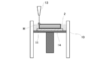
- the metal powder is newly supplied by moving the squeegee 12 in the horizontal direction on the previously formed block body 2 and the remaining metal powder, and has a desired thickness d.
- a new metal powder layer M is formed (first step).
- the surface of the new metal powder layer M is scanned with a laser beam, and the desired range of the metal powder layer M is irradiated with the laser beam.
- the metal powder of an irradiation part is heated locally, and this metal powder melts and solidifies, and the new block body 10 is modeled (2nd process).
- the metal powder is melted and solidified to form the block body 2, it is joined to the previously formed lower block body 2, so that the newly formed block body 2 is integrated with the lower block body 2. It will become.
- the block body 2 is stacked by repeatedly performing the first process and the second process described above, and as shown in FIGS. 7 to 9, the number of layers of the block body 2 reaches a predetermined number of layers.
- a layered object 1 having a three-dimensional shape is obtained.
- the irradiation conditions when irradiating the metal powder layer M with the laser beam that is, the output of the laser beam, the scanning speed, the scanning pitch, and the like are within a range of 1000 W or less if the output is, for example.
- the scanning speed can be adjusted as appropriate within a range of 7000 mm / s or less
- the scanning pitch can be adjusted within a range of 250 mm or less.
- the energy density E of the laser beam calculated by the following formula (1) from the following formula (1) is appropriately set for each composition of the metal powder, and the metal powder is irradiated with the laser beam under the optimal irradiation conditions, so that the finer It has been found that a layered object 1 having a high relative density can be produced.
- the energy is preferably a density E is 50 J / mm 3 or more 140 J / mm 3 or less (more preferably 87 J / mm 3 or so), preferably the energy density E when the silicon content of 7 wt% 35 J / mm 3 or more 115J / mm 3 or less (more preferably about 52J / mm 3) is preferably the energy density E when the silicon content of 10 mass% is 30 J / mm 3 or more 90 J / mm 3 or less (more preferably 62J / Mm about 3 ).
- the energy density E is preferably from 30 J / mm 3 or more 140 J / mm 3, more preferably not more than 50 J / mm 3 or more 90 J / mm 3.
- the layered object 1 is composed of a silicon-containing aluminum alloy containing aluminum as a main component and containing silicon less than 10% by mass (or 10% by mass or less when magnesium is not contained), and a plurality of block bodies 2 are laminated. It is integrated.
- the layered object 1 has a physical density of 97% or more relative to the theoretical density.
- the theoretical density of the alloy indicates the density of a dense smelted material having the same composition and without void defects
- the relative density indicates a percentage of a value obtained by dividing the measured density of the layered object by the theoretical density of the alloy.
- the actually measured density of the layered object can be measured, for example, by the Archimedes method.
- the density measurement by the Archimedes method can be performed according to “JIS Z 2501: Sintered metal material—Density, oil content and open porosity test method”.
- the relative density is preferably as high as possible, preferably 99% or more, and more preferably 99.5% or more.
- the layered object 1 according to the present invention has a tensile strength of 115 MPa or more as a mechanical strength.
- Tensile strength can be measured by the following procedure. For measurement, tensile strength of grade 1 or higher based on "JIS B 7721: Tensile tester / Compression tester-Calibration method and verification method of force measurement system" Use test equipment. First, a dumbbell-shaped test piece 3 shown in FIG. 10 is manufactured, and this test piece 3 is pulled at a rate of 1 mm / min using a tensile test device, and the maximum tensile stress that appears until the test piece 3 is broken is measured.
- the tensile strength is when the axial direction of the test piece 3 described above is a vertical direction that coincides with the stacking direction of the block bodies 2 of the layered object 1 and when it is a horizontal direction perpendicular to the stacking direction.
- the pressure may be 115 MPa or more in at least one case, but in any case, it is preferably 115 MPa or more.
- the tensile strength is 115 MPa or more, even if it is used for the above-described thermal control parts, various parts of automobiles and aircrafts, etc., a mechanical strength that can withstand practical use is ensured.
- the layered object 1 according to the present invention has a ductility of breaking elongation of 13% or more and more preferably 15% or more.
- the elongation at break can be measured by the following procedure. Two marks are attached to the main body portion 4 of the test piece 3 for tensile test described above so that the interval in the axial direction is about 12 mm. The actual distance between the two gauge points is measured and used as the initial gauge distance. Then, after performing the above-described tensile test on the test piece 3, the fracture surfaces are abutted with care so that the center lines of both fractured pieces of the test piece 3 are in a straight line, and the distance between the gauge points after the fracture is measured. To do. The elongation at break is expressed as a percentage obtained by dividing the difference between the distance between the marks after the break and the initial distance between the marks by the distance between the initial marks.
- the elongation at break is at least when the axial direction of the test piece 3 described above is a vertical direction coinciding with the stacking direction of the block body 2 of the layered object 1 and the horizontal direction perpendicular to the stacking direction. Although it may be 13% or more in one case, it is preferably 13% or more in any case. As described above, when the elongation at break is 13% or more, even when used in the above-described various parts of automobiles and airplanes, the ductility to the extent that it can be practically used is secured.
- the layered object 1 according to the present invention has a thermal conductivity of 120 W / m ⁇ K or more and more preferably 140 W / m ⁇ K or more as thermal conductivity.
- the thermal conductivity is measured by using a disk-shaped test plate (not shown) having a diameter of 10 mm and a thickness of 3 mm using, for example, a commercially available thermophysical property measuring device, “JIS H 7801-2005 metal thermal flash diffusivity by laser flash method. It can be measured by a method based on “Measurement Method”.
- the thermal conductivity is at least when the radial direction of the test plate described above is a vertical direction that coincides with the stacking direction of the block body 2 of the layered object 1 and when it is a horizontal direction perpendicular to the stacking direction. In one case, it may be 120 W / m ⁇ K or more, but in any case, it is preferably 120 W / m ⁇ K or more. As described above, when the thermal conductivity is 120 W / m ⁇ K or more, even when used in the above-described thermal control component or the like, the thermal conductivity to the extent that performance can be sufficiently exhibited is ensured.
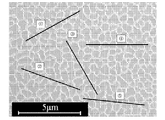
- the layered object 1 according to the present invention includes a metal structure in which fine columnar structures (cells) formed by solidification of a molten alloy, which are derived from the manufacturing method by the layered structure, are densely assembled. Are grown along the stacking direction of the block bodies 2 of the layered object 1 and arranged in a horizontal direction perpendicular to the stacking direction.
- the cell has an average particle size of 1.0 ⁇ m or less in a cross section perpendicular to the stacking direction of the block bodies 2 of the layered object 1.
- the mechanical strength of the layered object 1 is improved because the fine cells are densely arranged three-dimensionally, and even if used for the above-mentioned thermal control parts and various parts of automobiles and aircrafts, A mechanical strength sufficient to withstand practical use is ensured.
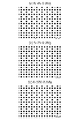
- the average particle size of the cell can be measured by the following procedure. First, a cylindrical test piece of an appropriate size is prepared, and a horizontal section perpendicular to the stacking direction of the block body 2 of the layered object 1 is polished to a mirror finish, and then etched with a Keller solution to form a micro metal structure. As shown in FIG. 11, the metal structure is photographed at a magnification of 10,000 times using a scanning electron microscope (SEM). Then, for example, as shown in FIG. 11, after drawing a straight line (measurement length of 5 ⁇ m or more) arbitrarily on the metal structure photograph, the number of cells crossed by the straight line is counted, and the length of the straight line is calculated as the cell length.
- SEM scanning electron microscope
- the value divided by the number is defined as the partial average particle size in the straight line.
- the number of cells is counted as 0.5.
- the average particle size of the cells can be measured. Note that the observation position is near the center of the scanning trace of a heat source such as a laser beam (position sufficiently away from the melting boundary). In FIG. 11, the results of actually measuring the average particle diameter of the cells are shown in Table 1 below.
- both mechanical strength, ductility, and thermal conductivity can be expected, and since it is lightweight, it is suitable for various parts of heat control parts and automobiles and aircraft. Can be applied.
- a cylindrical layered object (diameter 8 mm ⁇ height 15 mm) was manufactured by additive manufacturing using Al—Si based alloy powder in which the content of silicon (Si) was changed as the metal powder.
- the Al—Si based alloy powder was produced by a gas atomization method.
- the composition of each Al—Si based alloy powder is as shown in Table 2 below.
- a cylindrical layered object (diameter 8 mm ⁇ high height) is formed by additive manufacturing using Al—Si—Mg-based alloy powder to which magnesium (Mg) is added and the content of silicon (Si) is changed. 15 mm).
- the Al—Si—Mg alloy powder was produced by a gas atomization method.
- the composition of each Al—Si—Mg alloy powder is as shown in Table 3 below.
- the irradiation conditions of the laser beam by the laser beam scanning device for the Al—Si based alloy powder and the Al—Si—Mg based alloy powder during additive manufacturing are as follows.
- Laser type Yb fiber laser (spot diameter: about 0.1 mm, wavelength: about 1.07 ⁇ m) ⁇
- Lamination pitch 0.03mm
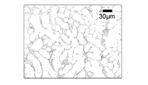
- a photograph of an optical microscope (OM) taken of a metal structure of a horizontal section perpendicular to the stacking direction of the block body of a layered object manufactured from each Al—Si based alloy powder and each Al—Si—Mg based alloy powder. Is shown in FIGS. 16 and 17.
- Al-Si-Mg-based alloy powder Al-7Si-0.3Mg
- the metal structure of the horizontal section is similarly obtained.
- a photograph taken with an optical microscope (OM) is shown in FIG. 18, and the tensile strength and elongation at break were measured. As a result, the tensile strength was 230 MPa and the elongation at break was 5.2%.
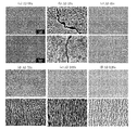
- FIG. 19 photographs taken with a scanning electron microscope (SEM) of the metal structure of the layered object manufactured from each Al—Si based alloy powder and each Al—Si—Mg based alloy powder are shown in FIG. 19 and FIG.
- the upper stage is a horizontal section perpendicular to the stacking direction of the block bodies, and the lower stage is a vertical section parallel to the stacking direction of the block bodies.
- this metal structure is a fine substantially columnar cell having an average particle diameter of 1.0 ⁇ m or less.
- the mechanical strength tensile strength
- a layered object manufactured with a metal powder having a silicon content of more than 1% by mass and not more than 10% by mass is excellent in practical use even when used for heat control parts and various parts of automobiles and aircrafts. It was confirmed that the mechanical strength was high enough to withstand and that the ductility was high enough.
- the layered object manufactured with the metal powder having a silicon content of more than 1% by mass and not more than 10% by mass has a high thermal conductivity of 120 W / m ⁇ K or more. It was confirmed that even if it was used as a heat control component, it had achieved thermal conductivity to the extent that sufficient performance could be exhibited.
- the layered object manufactured with the metal powder having a silicon content of greater than 1% by mass and less than or equal to 10% by mass can achieve both mechanical strength, ductility, and thermal conductivity, and is lightweight. Therefore, it was confirmed that the present invention can be suitably applied to heat control parts and various parts of automobiles and aircraft.
- the layered object manufactured with the metal powder not containing magnesium is mechanical strength (tensile compared with the layered object containing magnesium and containing the same mass% of silicon. Strength) was slightly reduced, but it was confirmed that the ductility and thermal conductivity were improved while mechanical strength sufficient to withstand practical use was ensured. Therefore, it was confirmed that the layered object manufactured with the metal powder not containing magnesium can realize higher ductility and thermal conductivity, and can be suitably applied to various parts of thermal control parts and automobiles and aircraft. .
Landscapes
- Engineering & Computer Science (AREA)
- Mechanical Engineering (AREA)
- Chemical & Material Sciences (AREA)
- Manufacturing & Machinery (AREA)
- Materials Engineering (AREA)
- Metallurgy (AREA)
- Organic Chemistry (AREA)
- Physics & Mathematics (AREA)
- Optics & Photonics (AREA)
- Powder Metallurgy (AREA)
- Laminated Bodies (AREA)
Abstract
L'invention concerne un article à pièces en stratifié moulées présentant une ductilité et une conductivité thermique élevées en plus d'une densité relative élevée. Un article à pièces en stratifié moulées 1 est fabriqué au moyen d'un moulage de pièces en stratifié par utilisation d'une poudre métallique de moulage de pièces en stratifié qui contient de l'aluminium comme constituant principal, qui contient, au total, 10 % en masse ou moins de silicium et de magnésium, et la quantité de silicium contenue étant supérieure à 1 % en masse.
Priority Applications (1)
| Application Number | Priority Date | Filing Date | Title |
|---|---|---|---|
| PCT/JP2016/065829 WO2017203717A1 (fr) | 2016-05-27 | 2016-05-27 | Poudre métallique de moulage de pièces en stratifié, procédé de fabrication d'article à pièces en stratifié moulées, et article à pièces en stratifié moulées |
Applications Claiming Priority (1)
| Application Number | Priority Date | Filing Date | Title |
|---|---|---|---|
| PCT/JP2016/065829 WO2017203717A1 (fr) | 2016-05-27 | 2016-05-27 | Poudre métallique de moulage de pièces en stratifié, procédé de fabrication d'article à pièces en stratifié moulées, et article à pièces en stratifié moulées |
Publications (2)
| Publication Number | Publication Date |
|---|---|
| WO2017203717A1 true WO2017203717A1 (fr) | 2017-11-30 |
| WO2017203717A8 WO2017203717A8 (fr) | 2017-12-21 |
Family
ID=60412457
Family Applications (1)
| Application Number | Title | Priority Date | Filing Date |
|---|---|---|---|
| PCT/JP2016/065829 Ceased WO2017203717A1 (fr) | 2016-05-27 | 2016-05-27 | Poudre métallique de moulage de pièces en stratifié, procédé de fabrication d'article à pièces en stratifié moulées, et article à pièces en stratifié moulées |
Country Status (1)
| Country | Link |
|---|---|
| WO (1) | WO2017203717A1 (fr) |
Cited By (8)
| Publication number | Priority date | Publication date | Assignee | Title |
|---|---|---|---|---|
| JP6635227B1 (ja) * | 2018-03-05 | 2020-01-22 | 三菱電機株式会社 | 三次元形状造形物の製造方法 |
| WO2021215306A1 (fr) * | 2020-04-21 | 2021-10-28 | 日本軽金属株式会社 | Corps moulé en aluminium et son procédé de production |
| CN116083760A (zh) * | 2022-11-14 | 2023-05-09 | 中国第一汽车股份有限公司 | 一种铝合金3d打印材料、铝合金3d打印零件以及制备方法 |
| CN116323046A (zh) * | 2020-10-12 | 2023-06-23 | 地方独立行政法人大阪产业技术研究所 | 增材制造用金属粉末、使用其的增材制造物的制造方法和增材制造物 |
| CN116504742A (zh) * | 2023-06-21 | 2023-07-28 | 青岛泰睿思微电子有限公司 | 半导体封装用框架及其制作方法、以及封装方法 |
| JP2024505349A (ja) * | 2020-12-26 | 2024-02-06 | オブシュチェストボ・エス・オグラニチェノイ・オトベツトベノスティウ“インスティテュート・レグキフ・マテリアロフ・アイ・テクノロジー” | 高い熱伝導率を有する粉状材料 |
| US12278031B2 (en) | 2019-11-11 | 2025-04-15 | Carpenter Technology Corporation | Soft magnetic composite materials and methods and powders for producing the same |
| JP2025161080A (ja) * | 2024-04-11 | 2025-10-24 | 株式会社ソディック | 三次元造形物の製造方法 |
Citations (2)
| Publication number | Priority date | Publication date | Assignee | Title |
|---|---|---|---|---|
| JP2016053198A (ja) * | 2014-09-04 | 2016-04-14 | 株式会社コイワイ | 金属成形体および金属成形体用金属粉末 |
| US20160138400A1 (en) * | 2014-11-17 | 2016-05-19 | Alcoa Inc. | Aluminum alloys having iron, silicon, vanadium and copper |
-
2016
- 2016-05-27 WO PCT/JP2016/065829 patent/WO2017203717A1/fr not_active Ceased
Patent Citations (2)
| Publication number | Priority date | Publication date | Assignee | Title |
|---|---|---|---|---|
| JP2016053198A (ja) * | 2014-09-04 | 2016-04-14 | 株式会社コイワイ | 金属成形体および金属成形体用金属粉末 |
| US20160138400A1 (en) * | 2014-11-17 | 2016-05-19 | Alcoa Inc. | Aluminum alloys having iron, silicon, vanadium and copper |
Cited By (14)
| Publication number | Priority date | Publication date | Assignee | Title |
|---|---|---|---|---|
| JP6635227B1 (ja) * | 2018-03-05 | 2020-01-22 | 三菱電機株式会社 | 三次元形状造形物の製造方法 |
| US12278031B2 (en) | 2019-11-11 | 2025-04-15 | Carpenter Technology Corporation | Soft magnetic composite materials and methods and powders for producing the same |
| EP4140617A4 (fr) * | 2020-04-21 | 2024-05-15 | Nippon Light Metal Co., Ltd. | Corps moulé en aluminium et son procédé de production |
| WO2021215306A1 (fr) * | 2020-04-21 | 2021-10-28 | 日本軽金属株式会社 | Corps moulé en aluminium et son procédé de production |
| JPWO2021215306A1 (fr) * | 2020-04-21 | 2021-10-28 | ||
| JP7179226B2 (ja) | 2020-04-21 | 2022-11-28 | 日本軽金属株式会社 | アルミニウム成形体及びその製造方法 |
| CN115427175A (zh) * | 2020-04-21 | 2022-12-02 | 日本轻金属株式会社 | 铝成型体及其制造方法 |
| CN116323046A (zh) * | 2020-10-12 | 2023-06-23 | 地方独立行政法人大阪产业技术研究所 | 增材制造用金属粉末、使用其的增材制造物的制造方法和增材制造物 |
| JP2024505349A (ja) * | 2020-12-26 | 2024-02-06 | オブシュチェストボ・エス・オグラニチェノイ・オトベツトベノスティウ“インスティテュート・レグキフ・マテリアロフ・アイ・テクノロジー” | 高い熱伝導率を有する粉状材料 |
| JP7691499B2 (ja) | 2020-12-26 | 2025-06-11 | オブシュチェストボ・エス・オグラニチェノイ・オトベツトベノスティウ“インスティテュート・レグキフ・マテリアロフ・アイ・テクノロジー” | 高い熱伝導率を有する粉状材料 |
| CN116083760A (zh) * | 2022-11-14 | 2023-05-09 | 中国第一汽车股份有限公司 | 一种铝合金3d打印材料、铝合金3d打印零件以及制备方法 |
| CN116504742B (zh) * | 2023-06-21 | 2023-12-08 | 青岛泰睿思微电子有限公司 | 半导体封装用框架及其制作方法、以及封装方法 |
| CN116504742A (zh) * | 2023-06-21 | 2023-07-28 | 青岛泰睿思微电子有限公司 | 半导体封装用框架及其制作方法、以及封装方法 |
| JP2025161080A (ja) * | 2024-04-11 | 2025-10-24 | 株式会社ソディック | 三次元造形物の製造方法 |
Also Published As
| Publication number | Publication date |
|---|---|
| WO2017203717A8 (fr) | 2017-12-21 |
Similar Documents
| Publication | Publication Date | Title |
|---|---|---|
| KR102364152B1 (ko) | 금속 분말, 적층 조형물의 제조방법 및 적층 조형물 | |
| WO2017203717A1 (fr) | Poudre métallique de moulage de pièces en stratifié, procédé de fabrication d'article à pièces en stratifié moulées, et article à pièces en stratifié moulées | |
| JP6803021B2 (ja) | 積層造形物の製造方法および積層造形物 | |
| CN107971489B (zh) | 铜合金粉末、层叠造型物的制造方法和层叠造型物 | |
| KR102668192B1 (ko) | 조형용 스테인레스강 분말 | |
| CN106964774B (zh) | 金属粉末、层叠造型物的制造方法以及层叠造型物 | |
| CN109396434B (zh) | 一种基于选区激光熔化技术制备钛合金零件的方法 | |
| JP5760222B2 (ja) | 金属ガラス成形体の製造方法 | |
| JPWO2018230421A1 (ja) | 造形物の製造方法、及び造形物 | |
| KR102239261B1 (ko) | 구리 합금 분말, 적층 조형물의 제조 방법 및 적층 조형물 | |
| Su et al. | An investigation into direct fabrication of fine-structured components by selective laser melting | |
| JP2019502028A5 (fr) | ||
| JP2016160454A (ja) | レーザー焼結積層方法、熱処理方法、金属粉末、及び、造形品 | |
| JP2017036508A (ja) | 金属粉末、積層造形物の製造方法および積層造形物 | |
| JP2017186653A (ja) | 三次元形状造形物及びその製造方法 | |
| JP2021085079A (ja) | 積層造形物の製造方法 | |
| Bonesso | Fusione a Letto di Polvere di Rame e Lega CuCrZr per Soluzioni di Esaurimento di Energia | |
| CN116847942A (zh) | 高速钢烧结体以及高速钢烧结体的制造方法 | |
| JP2024156538A (ja) | 銅合金粉末、それを用いた積層造形物、及び積層造形物からなる銅合金成形物 | |
| JP2024066625A (ja) | 銅合金粉末、積層造形物の製造方法、および積層造形物 | |
| KR20260040229A (ko) | 금속 분말, 금속 분말의 제조 방법, 및 금속 분말을 이용한 적층 조형물의 제조 방법 | |
| KR20210101418A (ko) | 타이타늄 조형물 적층방법 |
Legal Events
| Date | Code | Title | Description |
|---|---|---|---|
| 121 | Ep: the epo has been informed by wipo that ep was designated in this application |
Ref document number: 16903197 Country of ref document: EP Kind code of ref document: A1 |
|
| NENP | Non-entry into the national phase |
Ref country code: DE |
|
| 122 | Ep: pct application non-entry in european phase |
Ref document number: 16903197 Country of ref document: EP Kind code of ref document: A1 |
|
| NENP | Non-entry into the national phase |
Ref country code: JP |