WO2017203732A1 - 細胞壁又は細胞膜破砕装置及び該装置の使用方法 - Google Patents
細胞壁又は細胞膜破砕装置及び該装置の使用方法 Download PDFInfo
- Publication number
- WO2017203732A1 WO2017203732A1 PCT/JP2016/084844 JP2016084844W WO2017203732A1 WO 2017203732 A1 WO2017203732 A1 WO 2017203732A1 JP 2016084844 W JP2016084844 W JP 2016084844W WO 2017203732 A1 WO2017203732 A1 WO 2017203732A1
- Authority
- WO
- WIPO (PCT)
- Prior art keywords
- cell wall
- cell membrane
- sludge
- cell
- membrane crushing
- Prior art date
- Legal status (The legal status is an assumption and is not a legal conclusion. Google has not performed a legal analysis and makes no representation as to the accuracy of the status listed.)
- Ceased
Links
Images



Classifications
-
- C—CHEMISTRY; METALLURGY
- C12—BIOCHEMISTRY; BEER; SPIRITS; WINE; VINEGAR; MICROBIOLOGY; ENZYMOLOGY; MUTATION OR GENETIC ENGINEERING
- C12M—APPARATUS FOR ENZYMOLOGY OR MICROBIOLOGY; APPARATUS FOR CULTURING MICROORGANISMS FOR PRODUCING BIOMASS, FOR GROWING CELLS OR FOR OBTAINING FERMENTATION OR METABOLIC PRODUCTS, i.e. BIOREACTORS OR FERMENTERS
- C12M45/00—Means for pre-treatment of biological substances
- C12M45/02—Means for pre-treatment of biological substances by mechanical forces; Stirring; Trituration; Comminuting
-
- B—PERFORMING OPERATIONS; TRANSPORTING
- B02—CRUSHING, PULVERISING, OR DISINTEGRATING; PREPARATORY TREATMENT OF GRAIN FOR MILLING
- B02C—CRUSHING, PULVERISING, OR DISINTEGRATING IN GENERAL; MILLING GRAIN
- B02C19/00—Other disintegrating devices or methods
- B02C19/18—Use of auxiliary physical effects, e.g. ultrasonic waves or irradiation, for disintegrating
-
- A—HUMAN NECESSITIES
- A23—FOODS OR FOODSTUFFS; TREATMENT THEREOF, NOT COVERED BY OTHER CLASSES
- A23L—FOODS, FOODSTUFFS OR NON-ALCOHOLIC BEVERAGES, NOT OTHERWISE PROVIDED FOR; PREPARATION OR TREATMENT THEREOF
- A23L5/00—Preparation or treatment of foods or foodstuffs, in general; Food or foodstuffs obtained thereby; Materials therefor
- A23L5/30—Physical treatment, e.g. electrical or magnetic means, wave energy or irradiation
-
- B—PERFORMING OPERATIONS; TRANSPORTING
- B02—CRUSHING, PULVERISING, OR DISINTEGRATING; PREPARATORY TREATMENT OF GRAIN FOR MILLING
- B02C—CRUSHING, PULVERISING, OR DISINTEGRATING IN GENERAL; MILLING GRAIN
- B02C7/00—Crushing or disintegrating by disc mills
- B02C7/02—Crushing or disintegrating by disc mills with coaxial discs
-
- C—CHEMISTRY; METALLURGY
- C02—TREATMENT OF WATER, WASTE WATER, SEWAGE, OR SLUDGE
- C02F—TREATMENT OF WATER, WASTE WATER, SEWAGE, OR SLUDGE
- C02F11/00—Treatment of sludge; Devices therefor
-
- C—CHEMISTRY; METALLURGY
- C02—TREATMENT OF WATER, WASTE WATER, SEWAGE, OR SLUDGE
- C02F—TREATMENT OF WATER, WASTE WATER, SEWAGE, OR SLUDGE
- C02F11/00—Treatment of sludge; Devices therefor
- C02F11/02—Biological treatment
- C02F11/04—Anaerobic treatment; Production of methane by such processes
-
- C—CHEMISTRY; METALLURGY
- C02—TREATMENT OF WATER, WASTE WATER, SEWAGE, OR SLUDGE
- C02F—TREATMENT OF WATER, WASTE WATER, SEWAGE, OR SLUDGE
- C02F11/00—Treatment of sludge; Devices therefor
- C02F11/12—Treatment of sludge; Devices therefor by de-watering, drying or thickening
-
- C—CHEMISTRY; METALLURGY
- C12—BIOCHEMISTRY; BEER; SPIRITS; WINE; VINEGAR; MICROBIOLOGY; ENZYMOLOGY; MUTATION OR GENETIC ENGINEERING
- C12M—APPARATUS FOR ENZYMOLOGY OR MICROBIOLOGY; APPARATUS FOR CULTURING MICROORGANISMS FOR PRODUCING BIOMASS, FOR GROWING CELLS OR FOR OBTAINING FERMENTATION OR METABOLIC PRODUCTS, i.e. BIOREACTORS OR FERMENTERS
- C12M1/00—Apparatus for enzymology or microbiology
- C12M1/33—Disintegrators
-
- C—CHEMISTRY; METALLURGY
- C12—BIOCHEMISTRY; BEER; SPIRITS; WINE; VINEGAR; MICROBIOLOGY; ENZYMOLOGY; MUTATION OR GENETIC ENGINEERING
- C12N—MICROORGANISMS OR ENZYMES; COMPOSITIONS THEREOF; PROPAGATING, PRESERVING, OR MAINTAINING MICROORGANISMS; MUTATION OR GENETIC ENGINEERING; CULTURE MEDIA
- C12N1/00—Microorganisms; Compositions thereof; Processes of propagating, maintaining or preserving microorganisms or compositions thereof; Processes of preparing or isolating a composition containing a microorganism; Culture media therefor
- C12N1/06—Lysis of microorganisms
- C12N1/066—Lysis of microorganisms by physical processes
-
- A—HUMAN NECESSITIES
- A23—FOODS OR FOODSTUFFS; TREATMENT THEREOF, NOT COVERED BY OTHER CLASSES
- A23V—INDEXING SCHEME RELATING TO FOODS, FOODSTUFFS OR NON-ALCOHOLIC BEVERAGES AND LACTIC OR PROPIONIC ACID BACTERIA USED IN FOODSTUFFS OR FOOD PREPARATION
- A23V2002/00—Food compositions, function of food ingredients or processes for food or foodstuffs
-
- C—CHEMISTRY; METALLURGY
- C02—TREATMENT OF WATER, WASTE WATER, SEWAGE, OR SLUDGE
- C02F—TREATMENT OF WATER, WASTE WATER, SEWAGE, OR SLUDGE
- C02F2201/00—Apparatus for treatment of water, waste water or sewage
- C02F2201/002—Construction details of the apparatus
- C02F2201/003—Coaxial constructions, e.g. a cartridge located coaxially within another
-
- C—CHEMISTRY; METALLURGY
- C02—TREATMENT OF WATER, WASTE WATER, SEWAGE, OR SLUDGE
- C02F—TREATMENT OF WATER, WASTE WATER, SEWAGE, OR SLUDGE
- C02F2303/00—Specific treatment goals
- C02F2303/02—Odour removal or prevention of malodour
-
- C—CHEMISTRY; METALLURGY
- C02—TREATMENT OF WATER, WASTE WATER, SEWAGE, OR SLUDGE
- C02F—TREATMENT OF WATER, WASTE WATER, SEWAGE, OR SLUDGE
- C02F2303/00—Specific treatment goals
- C02F2303/26—Reducing the size of particles, liquid droplets or bubbles, e.g. by crushing, grinding, spraying, creation of microbubbles or nanobubbles
-
- Y—GENERAL TAGGING OF NEW TECHNOLOGICAL DEVELOPMENTS; GENERAL TAGGING OF CROSS-SECTIONAL TECHNOLOGIES SPANNING OVER SEVERAL SECTIONS OF THE IPC; TECHNICAL SUBJECTS COVERED BY FORMER USPC CROSS-REFERENCE ART COLLECTIONS [XRACs] AND DIGESTS
- Y02—TECHNOLOGIES OR APPLICATIONS FOR MITIGATION OR ADAPTATION AGAINST CLIMATE CHANGE
- Y02A—TECHNOLOGIES FOR ADAPTATION TO CLIMATE CHANGE
- Y02A40/00—Adaptation technologies in agriculture, forestry, livestock or agroalimentary production
- Y02A40/10—Adaptation technologies in agriculture, forestry, livestock or agroalimentary production in agriculture
- Y02A40/20—Fertilizers of biological origin, e.g. guano or fertilizers made from animal corpses
-
- Y—GENERAL TAGGING OF NEW TECHNOLOGICAL DEVELOPMENTS; GENERAL TAGGING OF CROSS-SECTIONAL TECHNOLOGIES SPANNING OVER SEVERAL SECTIONS OF THE IPC; TECHNICAL SUBJECTS COVERED BY FORMER USPC CROSS-REFERENCE ART COLLECTIONS [XRACs] AND DIGESTS
- Y02—TECHNOLOGIES OR APPLICATIONS FOR MITIGATION OR ADAPTATION AGAINST CLIMATE CHANGE
- Y02E—REDUCTION OF GREENHOUSE GAS [GHG] EMISSIONS, RELATED TO ENERGY GENERATION, TRANSMISSION OR DISTRIBUTION
- Y02E50/00—Technologies for the production of fuel of non-fossil origin
- Y02E50/30—Fuel from waste, e.g. synthetic alcohol or diesel
-
- Y—GENERAL TAGGING OF NEW TECHNOLOGICAL DEVELOPMENTS; GENERAL TAGGING OF CROSS-SECTIONAL TECHNOLOGIES SPANNING OVER SEVERAL SECTIONS OF THE IPC; TECHNICAL SUBJECTS COVERED BY FORMER USPC CROSS-REFERENCE ART COLLECTIONS [XRACs] AND DIGESTS
- Y02—TECHNOLOGIES OR APPLICATIONS FOR MITIGATION OR ADAPTATION AGAINST CLIMATE CHANGE
- Y02W—CLIMATE CHANGE MITIGATION TECHNOLOGIES RELATED TO WASTEWATER TREATMENT OR WASTE MANAGEMENT
- Y02W10/00—Technologies for wastewater treatment
- Y02W10/30—Wastewater or sewage treatment systems using renewable energies
- Y02W10/37—Wastewater or sewage treatment systems using renewable energies using solar energy
-
- Y—GENERAL TAGGING OF NEW TECHNOLOGICAL DEVELOPMENTS; GENERAL TAGGING OF CROSS-SECTIONAL TECHNOLOGIES SPANNING OVER SEVERAL SECTIONS OF THE IPC; TECHNICAL SUBJECTS COVERED BY FORMER USPC CROSS-REFERENCE ART COLLECTIONS [XRACs] AND DIGESTS
- Y02—TECHNOLOGIES OR APPLICATIONS FOR MITIGATION OR ADAPTATION AGAINST CLIMATE CHANGE
- Y02W—CLIMATE CHANGE MITIGATION TECHNOLOGIES RELATED TO WASTEWATER TREATMENT OR WASTE MANAGEMENT
- Y02W30/00—Technologies for solid waste management
- Y02W30/40—Bio-organic fraction processing; Production of fertilisers from the organic fraction of waste or refuse
Definitions
- the present disclosure relates to an apparatus for crushing cell walls and / or cell membranes of microorganisms, algae, and the like and a method for using the apparatus.
- Microorganisms and algae contained in organic sludge contain various useful resources (for example, proteins, fats, and carbohydrates).
- useful resources for example, proteins, fats, and carbohydrates.
- cell walls and the like Since cell walls and the like constituting microorganisms and the like are composed of very strong membranes, in order to crush the cell walls and the like, advanced techniques and complicated facilities are generally required. As a result, conventional methods and equipment have resulted in increased running costs.
- Patent Document 1 is a sludge crushing device that crushes sludge generated by biological treatment of organic sewage, and includes a rotating disk that rotates at high speed, and a driving means that drives the rotating disk, and rotates.
- the disk further includes a fixed disk facing the disk and having a sludge inlet in the center, and a disk gap of approximately 5 mm or more is provided between the fixed disk and the rotating disk, and sludge is mainly collected by the rotational shearing force of the rotating disk.
- a sludge crushing device for crushing is disclosed.
- Patent Document 2 discloses a sludge treatment method in which sludge generated in wastewater treatment is subjected to ultrasonic treatment in an ultrasonic treatment step and then treated in a methane fermentation step after the sludge is decomposed in a sludge decomposition step. .
- digestion of organic sludge in surplus sludge in an activated sludge concentration tank is performed by solubilizing and hydrolyzing microorganisms in the sludge and generating water and carbon dioxide.
- the elution of intracellular high-molecular substances such as proteins, organic acids, lipids, and carbohydrates contained in microorganisms and the lowering of the molecular weight by hydrolysis of these substances are rate-limiting. Digestion of organic sludge took a long digestion day.
- Examples of conventional techniques for disrupting cell walls to reduce molecular weight and solubilize include high-energy disruption methods such as ultrasound; chemical decomposition methods such as ozone oxidation and alkali treatment; mechanical disruption methods using homogenizers, mills, etc. It is done. In some cases, a heating means of 50 ° C. or higher is further employed to facilitate crushing of cell walls and the like.
- the method of using ultrasonic waves, ozone, and alkali has a problem that the maintenance cost of the apparatus increases.
- the mechanical crushing method using a homogenizer, a mill, or the like has a problem that the cost is similarly increased because the processing efficiency is low and it is necessary to make a complicated and large apparatus.
- the present disclosure provides an apparatus that can efficiently crush cell walls and the like of microorganisms at low cost and a method for using the apparatus.
- a cell wall or cell membrane crushing apparatus including a fixed disk, a rotating disk, a rotating shaft for driving the rotating disk, a decompression unit, and a housing, and at least of the fixed disk and the rotating disk.
- One set is arranged to face each other, and the center portion of the fixed disk has a cavity portion that is larger than the outer diameter of the rotating shaft passing through the center portion, and the shearing force generated between the rotating disk and the fixed disk.
- a cell wall comprising a stationary disk, a rotating disk, a rotating shaft for driving the rotating disk, a pressure reducing means by a suction force of a land-type pump and / or a submersible pump, and a housing
- a cell membrane crushing device wherein at least one set of a fixed disk and a rotating disk are arranged to face each other, and a central part of the fixed disk has a cavity larger than an outer diameter of a rotating shaft passing through the central part.
- the land-type pump is used. Is installed after the discharge port of the device, and when a submersible pump is used, the submersible pump is provided by a cell wall or cell membrane crushing device installed on the discharge port side after the last fixed disk in the device. It is.
- a sludge volume reduction method including a step of treating sludge with the above-described cell wall or cell membrane crushing apparatus.
- a method for preparing sludge fertilizer comprising the steps of treating sludge with the above-described cell wall or cell membrane crushing device, and treating the sludge obtained from the step of treating sludge.
- the sludge is provided with a step of treating sludge with the above-described cell wall or cell membrane crushing apparatus, and a step of collecting the treated separation liquid obtained from the step of treating sludge as a culture solution.
- a method for preparing a culture solution is provided.
- a deodorization method including a step of treating sewage and / or sludge or odorous food with the above-described cell wall or cell membrane crushing apparatus.
- a treated sludge and / or treated separated liquid obtained from the step of treating sludge by the above-described cell wall or cell membrane crushing device and the step of treating sludge is provided to the biogas fermenter.
- a biogas fermentation method comprising the step of:
- At least one selected from the group of fungi, microorganisms, algae, and plants (hereinafter sometimes referred to as “microbe group”) by the cell wall or cell membrane crushing device described above.
- an object eg, sludge
- at least one oil selected from the group of fungi, microorganisms, algae, and plants is processed by the above-described cell wall or cell membrane crushing apparatus.
- An oil recovery method comprising the steps is provided.
- the cell wall or cell membrane crushing device of the present disclosure only needs to have a simple configuration of at least a fixed disk, a rotating disk, a rotating shaft for driving the rotating disk, a decompression unit, and a housing.
- An easy and low cost apparatus can be provided.
- the conventional apparatus requires additional facilities such as alkali treatment and heating treatment at 50 ° C. or higher in order to crush the cell wall and the like.
- the cell wall or cell membrane crushing device of the present disclosure includes a decompression unit, there is no need to include facilities such as alkali treatment and heating treatment at 50 ° C. or higher. As a result, the running cost can be greatly reduced as compared with conventional devices and equipment.
- the cell wall or cell membrane crushing device of the present disclosure can be used for sludge volume reduction method, sludge fertilizer preparation method, sludge culture solution preparation method, deodorization method, biogas fermentation method, food, beverage, pharmaceutical, supplements or cosmetics. It can be used in production methods, oil content recovery methods, and the like. Since the cell wall or cell membrane crushing device of the present disclosure can sufficiently crush the cell wall and the like without adversely affecting the active ingredient contained in the microorganism or the like, the efficiency in each method described above can be improved.
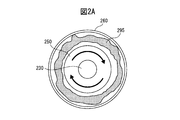
- FIG. 2 is an enlarged cross-sectional view of the A-A ′ plane in FIG. 1.
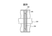
- FIG. 2 is an enlarged view of a rotating disk in the vicinity of A-A ′ in FIG. 1.
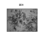
- It is a microscope picture (150 times) of the sludge concentrated by centrifugation.
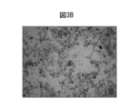
- It is a microscope picture (150 times) of the sludge after a cell wall or a cell membrane crusher process.
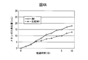
- It is a figure which shows the cumulative generation amount of the methane gas in the batch type test under anaerobic conditions.
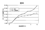
- It is a figure which shows the conversion efficiency to methane gas in the batch type test under anaerobic conditions.
- the cell wall or cell membrane crushing apparatus is a cell wall or cell membrane crushing apparatus including a fixed disk, a rotating disk, a rotating shaft for driving the rotating disk, a decompression unit, and a housing, At least one set of the disk and the rotating disk is disposed so as to face each other, and the center portion of the fixed disk has a hollow portion larger than the outer diameter of the rotating shaft passing through the center portion, The shearing force generated between them is applied to the fluid of the object having a water content of 89% or more that is input into the apparatus. Since the cell wall or cell membrane crushing apparatus of the present disclosure has a simple configuration, the apparatus can be easily maintained and the manufacturing cost of the apparatus can be reduced. As a result of adopting the pressure reducing means, facilities such as alkali treatment and heating treatment, which were essential in the conventional apparatus, are no longer necessary, and the running cost can be greatly reduced.
- the cell wall or cell membrane crushing apparatus includes a fixed disk, a rotating disk, a rotating shaft for driving the rotating disk, a decompression unit and a housing by a suction force of a land-type pump and / or a submersible pump.
- a cell wall or cell membrane crushing device wherein at least one set of a fixed disk and a rotating disk are arranged to face each other, and a center part of the fixed disk is larger than an outer diameter of a rotating shaft passing through the center part
- the shearing force generated between the rotating disk and the stationary disk is applied to the fluid of the object having a moisture content of 89% or more that is charged into the apparatus.
- the land-type pump is installed after the discharge port of the apparatus, and when the submersible pump is used, the submersible pump is installed on the discharge port side after the last fixed disk in the apparatus.
- the cell wall or cell membrane crushing device of the present disclosure is not limited to a decompression pump, and can reduce the pressure inside the device using a land-type pump or a submersible pump. Therefore, maintenance is easier, compared to using a decompression pump. Maintenance costs can be greatly reduced.
- the pressure in the apparatus can be reduced to ⁇ 0.08 MPa or less by a decompression unit.
- a pressure difference is generated between the internal pressure from the cell wall and the external pressure from the cell wall, and thus the cell wall and the like are easily crushed.
- the shearing force between the fixed disk and the rotating disk increases, and the cell walls and the like are easily crushed and cavitation occurs simultaneously, so that the cell walls and the like are more easily crushed.
- the land-type pump of the cell wall or cell membrane crushing apparatus in the second embodiment may be a single screw pump.
- a single screw pump is preferable because it has excellent suction power among land-based pumps.
- the rotating disk of the cell wall or cell membrane crushing apparatus in the first or second embodiment can rotate at a peripheral speed of 10 m / s or more.
- the peripheral speed of the rotating disk is 10 m / s or more, the shearing force between the fixed disk and the rotating disk is improved, and the cell wall and the like can be more efficiently crushed.
- the cell wall or cell membrane crushing apparatus in the first or second embodiment can include two or more fixed disks and / or rotating disks. By providing two or more fixed disks and / or rotating disks, the cell walls and the like can be more efficiently crushed in a short time.
- the gap between the fixed disk and the rotating disk in the cell wall or cell membrane crushing apparatus in the first or second embodiment can be 5 mm to 30 mm.
- the gap between the fixed disk and the rotating disk is within this range, the shearing force between the fixed disk and the rotating disk is improved, and the cell wall and the like can be more efficiently crushed.
- the surface of the rotating disk and / or fixed disk in the cell wall or cell membrane crushing apparatus in the first or second embodiment may be a mirror surface or a rough surface. If the surface of the disk is mirrored, the object will flow more easily, so the flow velocity of the object can be improved. If the surface is rough, the frictional force or surface area of the disk surface will increase, so the cell wall The shearing force required for crushing such as can be applied to the object more effectively.
- the object thrown into the cell wall or cell membrane crushing apparatus in the first or second embodiment may include at least one selected from the group of fungi, microorganisms, algae, and plants. Moreover, you may use sludge as a target object.
- the cell wall or cell membrane crushing apparatus is applied to a sludge volume reduction method, a sludge fertilizer preparation method, a sludge culture solution preparation method, a deodorization method, a biogas fermentation method, a food, a beverage, and a pharmaceutical product. It can be used in a method for producing supplements or cosmetics, and a method for oil recovery.
- An object including microorganisms and the like processed by the cell wall or cell membrane crushing apparatus can improve efficiency in the above-described methods because the cell wall and the like are sufficiently crushed.
- cavitation is considered to be a phenomenon in which bubbles (pockets) are instantaneously generated due to vaporization of a low pressure portion in a fluid moving in a cell wall or cell membrane crushing device, and then collapse and disappear. Yes. It is said that the local impact force generated when bubbles in cavitation collapse is 100 MPa to several GPa, and the temperature environment is 1,200 ° C. or higher. At this time, it is considered that a stronger shearing force acts and the cell wall and the like are more easily crushed.
- biogas is a kind of biofuel, and means gas (methane gas, hydrogen gas, etc.) generated by fermentation of sludge and sewage.
- sludge means a liquid substance containing a final product of organic matter as a solid content, which is generated in a treatment process of a sewage treatment plant, a waste liquid treatment process of a factory, or the like.
- Sludge includes “excess sludge” generated by the activated sludge method.
- Excess sludge refers to the portion of the activated sludge that has been treated in the activated sludge reaction tank, introduced into the final sedimentation basin, etc., and excluding the portion that is returned to the activated sludge reaction tank as return sludge. is there.
- the surplus sludge is mainly composed of microorganisms grown using dissolved organic substances in the sewage as a substrate, and protozoa grown by feeding on the microorganisms.
- suspended substance concentration means the amount of activated sludge in the aeration tank or aeration tank (reaction tank) in the activated sludge method expressed in mg / L; “Substance concentration (MLVSS)” means the loss of ignition loss (VS) of MLSS in mg / L; “Floating substance (SS)” means all substances floating in water.
- Biochemical oxygen demand means the amount of dissolved oxygen consumed by aerobic microorganisms in water
- Total organic carbon means in the organic matter present in water Means the amount of carbon
- dissolved organic carbon means the amount of carbon in organic matter dissolved in water
- total nitrogen exists in water Means the total amount of nitrogen compounds
- total phosphorus amount means It means the total amount of the phosphorus compounds present in.
- the suspended solids concentration (MLSS) and suspended solids (SS) shall be determined according to the sewerage test method (Japan Sewerage Association, 1997, Volume 2, Chapter 2, Section 12-2). Adopted and measured.
- FIG. 1 is a schematic cross-sectional view of a cell wall or cell membrane crusher 100 according to a first embodiment of the present disclosure.
- the cell wall or cell membrane crushing apparatus 100 is positioned in the horizontal direction of the center of the cell wall or cell membrane crushing apparatus 100, the casing 160, the fixed disk 140 disposed on the inner surface of the casing 160, the rotating disk 150, and the rotating disk 150.
- the rotary shaft 130 for fixing and driving, the input port 170, the discharge port 180, and the decompression means 190 are provided.
- the cell wall or cell membrane crusher 100 can include an inverter 110 and a motor 120 for driving the rotating shaft 130.
- the inverter 110 and the motor 120 may be configured integrally with the cell wall or cell membrane crusher 100 or may be disposed outside the cell wall or cell membrane crusher 100.
- the use of an inverter is preferable because the peripheral speed can be appropriately adjusted according to the type and amount of the object, but a star delta (Y- ⁇ ) motor or the like may be employed instead of the inverter.
- the target object that has been input to the input port 170 flows between the fixed disk 140 and the rotating disk 150 and is discharged from the discharge port 180, as in the target object flow 105 of FIG.
- the input port 170 and the discharge port 180 may be arranged in reverse.
- the cell walls of microorganisms and the like contained in the object are crushed by energy such as shearing force generated between the fixed disk 140 and the outer surface of the rotating shaft 130 (FIGS. 3A and 3B).
- FIGS. 2A and 2B show an enlarged cross-sectional view of the A-A ′ surface of the cell wall or cell membrane crushing apparatus 100 in FIG. 1 and an enlarged view of a rotating disk in the vicinity of A-A ′.
- a low pressure portion is formed in the object.
- Water or the like in the object is vaporized by the low pressure part to generate bubbles, and a cloud 295 (mixed part of liquid and gas) is formed in the object.
- a very high pressure impact force
- the energy based on this high pressure also contributes to the crushing of cell walls as a shearing force.
- various materials can be used depending on applications. Although not limited to these, for example, one or more materials selected from the group consisting of metals or metal alloys such as iron and stainless steel, ceramics, glass, plastics, reinforced resins including carbon fibers and / or glass fibers, and rubbers. Can be used. Of these, stainless steel (SUS316 and the like) and ceramics are preferable because they are excellent in strength and rust prevention effect.
- the surface of various members that come into contact with the object is treated with water-repellent treatment with fluororesin coating, titanium oxide, silicon oxide Hydrophilic treatment by coating or the like, smooth surface (mirror surface) treatment, or roughening treatment may be applied.
- water repellent treatment or the hydrophilic treatment it is possible to prevent adhesion of dirt or the like based on the object.
- smooth surface (mirror surface) process By applying the smooth surface (mirror surface) process, the object easily flows, so that the flow velocity of the object can be improved.
- the roughening treatment the frictional force and the surface area increase, so that the generation of shearing force and cavitation can be improved.
- Water repellent treatment, hydrophilic treatment, smooth surface (mirror surface) treatment, and roughening treatment may be used in combination. Moreover, you may apply these processes to the whole surface or part of member to apply.
- the surface roughening treatment include embossing, sandblasting, cutting, polishing, laser processing, etching processing, and the like, and molding using an uneven mold.
- a member that can give a rough surface to the surface of a fixed disk or the like may be bonded using an adhesive, welding, a bolt, or the like.
- the rough surface may be a random uneven shape, or may be a groove-like shape having a predetermined angle and / or interval. The size and shape of the rough surface can be appropriately adjusted according to the properties of the object and the amount of processing.
- the central portion of the fixed disk 140 has a hollow portion that is larger than the outer diameter of the rotating shaft 130 that passes through the central portion.
- the fixed disk 140 may be appropriately adjusted in outer diameter, inner diameter, shape, thickness, and quantity in accordance with the properties, processing amount, shape of the casing, design intention, etc. of the object to be inserted into the cell wall or cell membrane crushing apparatus 100. Can do. Considering crushability of the cell wall and the like, manufacturing cost, etc., the fixed disk 140 preferably has a substantially disk shape, and the cavity of the fixed disk 140 preferably has a substantially circular shape. The size of the cavity of the fixed disk 140 can be appropriately adjusted according to the type and amount of the object.
- the surface of the fixed disk 140 may have a concave or convex slope as long as it does not hinder the occurrence of shearing force and cavitation. You may have.
- the fixed disk 140 may be integrated with the inner wall of the housing 160 by an adhesive, welding, or the like, or may be removably attached using a bolt or the like. Further, the fixed disk 140 and the housing 160 may be a single body made of one material using a 3D printer or the like.
- the rotating disk 150 is appropriately adjusted in outer diameter, inner diameter, shape, thickness, and quantity in accordance with the properties, processing amount, shape of the casing, design intention, and the like of the object to be inserted into the cell wall or cell membrane crushing apparatus 100. Can do. In consideration of the crushability of the cell wall and the like, the manufacturing cost, etc., the rotating disk 150 preferably has a substantially disk shape. The distance between the outer periphery of the rotating disk 150 and the inner wall of the housing can also be adjusted as appropriate according to the type and amount of the object.
- the surface of the rotating disk 150 may have a concave or convex inclination as long as shearing force and cavitation are not hindered, and may have a through-hole or the like in the disk or on the outer periphery.
- the rotating disk 150 may be integrated with the rotating shaft 130 by an adhesive, welding, or the like, or may be removably attached using a bolt or the like. Further, the rotating disk 150 and the rotating shaft 130 can be formed as a single body made of one material using a 3D printer or the like.
- the rotational speed and peripheral speed of the rotating disk 150 can be appropriately adjusted according to the type and amount of the object, and are not limited to the following ranges.
- Rotational speed of the rotating disk 150, 1000min -1 or more, 2000 min -1 or more, or 3000 min -1 or more, 7000Min -1 or less, can be 6000 min -1 or less, or 5000 min -1 or less.
- the peripheral speed of the rotating disk 150 can be adjusted to a predetermined range.
- the peripheral speed of the rotating disk 150 can be 20 m / s or more, 30 m / s or more, 35 m / s or more, 70 m / s or less, 60 m / s or less, or 55 m / s or less.
- the peripheral speed is preferably in the range of 37 to 52 m / s because cavitation is likely to occur in addition to the shearing force.
- the fixed disk 140 in the cell wall or cell membrane crushing apparatus 100 of the present disclosure has a hollow portion (object suction port) at the center and is disposed so as to face the rotating disk 150.
- the fixed disk 140 forms a flow in which the object that flows in the outer circumferential direction of the rotating disk 150 flows again through the cavity of the fixed disk 140 and flows into the center of the rotating disk 150 due to the centrifugal force of the rotating disk 150. It has the function to do. In other words, the fixed disk 140 functions to make the object in the cell wall or cell membrane crusher 100 uniform.
- the cell wall or cell membrane crushing apparatus 100 of the present disclosure only needs to include one or more fixed disks 140 and one rotating disk 150, but from the viewpoint of crushing efficiency of cell walls or the like, two or more of these disks should be provided. Is preferred.
- the fixed disk and the rotating disk may be alternately arranged, and two or more fixed disks may be arranged between the rotating disk and the rotating disk.
- the sizes and shapes of the rotating disk and the fixed disk that are arranged may be unified or different.
- the gap between the fixed disk and the rotating disk or the gap between the fixed disks is determined by the size (inner diameter, outer diameter) of the rotating disk and fixed disk to be used, the rotational speed of the rotating disk, the properties of the object, the processing amount, etc. Although it should be and does not specifically limit this invention, it is preferable that they are 5 mm or more, 7 mm or more, or 9 mm or more, 30 mm or less, 20 mm or less, or 15 mm or less. Among these, the range of 10 mm to 11 mm is preferable in consideration of shearing force and cavitation.
- the intervals between the disks may be constant or different, but are preferably different.
- the interval between the disks can be increased continuously, stepwise, or partially from the inlet side toward the outlet side.
- the distance between the disks can be 10 mm from the inlet to the vicinity of the center of the apparatus, and the distance between the disks can be gradually increased to 11 mm from the vicinity of the center of the apparatus to the outlet.
- the interval between the disks is reduced in the vicinity of the insertion port, the flow rate of the object is increased, and the crushability of the cell wall and the like is improved.
- the interval between the disks is increased in the vicinity of the discharge port, the flow rate of the object becomes gentle, so that clogging of the object in the apparatus can be prevented.
- the cell wall or cell membrane crusher 100 of the present disclosure may further include a disk gap adjusting unit that adjusts the disk gap.
- the disk gap adjusting means When the disk gap adjusting means is employed, the disk gap can be suitably adjusted in consideration of the properties of the object to be processed, so that the cell wall or cell membrane crushing device of the present disclosure can be used more effectively. .
- the rotating shaft 130 is located in the center horizontal direction of the cell wall or cell membrane crushing apparatus 100, and is for fixing and driving the rotating disk 150.
- the rotating shaft 130 may be provided with a decompression unit 190 shown below. If the pressure can be reduced through the rotating shaft 130, the inside of the apparatus can be uniformly reduced.
- the casing 160 is a member that covers the outer periphery of the cell wall or the cell membrane crushing apparatus 100, and the shape, size, material, and the like may be adjusted as appropriate according to the intended use of the apparatus. In consideration of generation of shearing force and production cost, a cylindrical housing made of stainless steel (SUS316 or the like) is preferable.
- the decompression means 190 has a function of generating a pressure difference between the inside and outside of a cell such as a microorganism to facilitate crushing of the cell wall and the like.
- a cell such as a microorganism
- the decompression means 190 since the cell wall and the like are crushed by adopting the decompression means 190, it is no longer necessary to use an alkali treatment or a heating treatment at 50 ° C. or higher, which has been conventionally used. Therefore, compared with the conventional apparatus and equipment, the equipment space can be simplified and the running cost can be greatly reduced.
- the cell wall or cell membrane crusher 100 of the present disclosure does not limit the use of alkali treatment, heating treatment at 50 ° C. or higher, and the like. Needless to say, when these treatments are used in combination, the disruption of cell walls and the like is further improved as compared with conventional devices and equipment.
- the decompression conditions in the cell wall or cell membrane crushing apparatus can be adjusted as appropriate according to the type and amount of the object, and are not limited to the following ranges.
- the pressure in the cell wall or cell membrane crusher can be reduced to ⁇ 0.1 MPa or less, ⁇ 0.09 MPa or less, or ⁇ 0.08 MPa or less by a decompression unit.
- the pressure is preferably ⁇ 0.080 MPa ( ⁇ 80 kPa) or less, ⁇ 0.065 MPa ( ⁇ 65 kPa) or less, or ⁇ 0.060 MPa ( ⁇ 60 kPa) or less.
- the lower limit of the pressure is not particularly limited, but is set to ⁇ 0.01 kPa ( ⁇ 0.00001 MPa) or more, ⁇ 0.05 kPa ( ⁇ 0.00005 MPa) or more, or ⁇ 0.1 kPa ( ⁇ 0.0001 MPa) or more. Also good.
- the pressure range is preferably -0.01 kPa to -0.080 MPa, more preferably -0.05 kPa to -0.065 MPa, and most preferably -0.1 kPa to -0.060 MPa. These pressure values are expressed in gauge pressure with reference to atmospheric pressure (zero). Note that the reduced pressure is a concept including a negative pressure.
- the pressure reducing means 190 is not limited to these, a pressure reducing pump such as a rotary pump or a dry pump can be used.
- the decompression means 190 may be provided integrally with the cell wall or cell membrane crusher 100. In this case, the decompression unit 190 can be disposed at one or more locations selected from the group of the inlet 170, the casing 160, the rotating shaft 130, and the outlet 180. Alternatively, the decompression unit 190 may be arranged separately from the cell wall or cell membrane crusher 100. In this case, the decompression unit 190 can be disposed at one or more locations selected from the group of the input port 170, the housing 160, the drive unit 130, and the discharge port 180 via a pipe or the like.
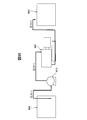
- a land-type pump 815 is installed between a pretreatment reservoir 805 for storing an object such as sludge and a cell wall or cell membrane crusher 800.
- a land-type pump for example, a single screw pump can be used. Among these, a single screw pump excellent in performance such as suction is preferable.
- MONO PUMP registered trademark manufactured by Hyojin Equipment Co., Ltd. can be used.
- the land-type pump 815 is installed between the cell wall or cell membrane crushing apparatus 800 and the post-treatment storage tank 825 for storing the object processed by the apparatus.
- the cell wall or cell membrane crushing apparatus 800 receives the suction force based on the land-type pump 815, so that the inside of the apparatus is decompressed.
- the cell wall or the cell membrane crusher 800 is filled with the object.
- the suction force is weak and may be subject to installation restrictions, a single screw pump type that is excellent in suction force is desirable. Therefore, in the case of the installation configuration, it is preferable that the object is introduced from the lower part of the apparatus and discharged from the upper part (in this case, the object flow 105 in FIG. 1 is in the reverse direction, and 170 is the discharge port, 180 is the slot.) In the case of the installation configuration of FIG.
- the equipment can be further simplified as compared with the installation configuration of FIG. 8A.
- the above-described decompression pump may be used in combination.
- the structure of FIG. 8B intends to introduce
- transduce a target object into the cell wall or cell membrane crushing apparatus 800 using the dead weight of a target object from the lower part of the storage tank before a process the storage tank 805 before a process and a cell wall
- the land-type pump 815 is not installed between the cell membrane crusher 800.
- a land-type pump 815 may be further installed between the pre-treatment reservoir 805 and the cell wall or cell membrane crusher 800 to take out the object from the upper part of the pre-treatment reservoir.
- . 8B shows an example in which a land-type pump 815 is disposed between the cell wall or cell membrane crushing apparatus 800 and the post-treatment storage tank 825.
- the land-type pump 815 includes the cell wall or cell membrane crushing apparatus 800. It only needs to be installed after the discharge port.
- the rear stage of the land-type pump 815 is not limited to the post-treatment storage tank 825, and various processing apparatuses may be arranged, or the rear stage of the land-type pump 815 may be directly connected to predetermined various facilities. .
- this submersible pump should just be installed in the position immersed in the target by the side of the discharge port after the last fixed disk in the cell wall or the cell membrane crushing apparatus 800.
- the cell wall or cell membrane crusher 100 of the present disclosure may further include a heating means.
- a heating means a conventionally used heating means of 50 ° C. or higher can also be used. However, it is preferable not to employ a heating means of 170 ° C. or higher, 150 ° C. or higher, or 120 ° C. or higher because of increased energy costs and the possibility of causing problems in the cell wall or cell membrane crushing apparatus.
- the heating means of 30 degreeC or more and less than 50 degreeC which has not been used conventionally can also be used. Conventional heating means of 50 ° C. or higher is employed for the purpose of making cell walls and the like flexible.
- the cell wall or cell membrane crushing apparatus 100 of the present disclosure includes the decompression unit 190, cavitation is easily generated even when heating at 30 ° C. or more and less than 50 ° C., and the crushing of the cell wall or the like can be further improved.
- heating means known means such as exhaust heat discharged from a steam jacket, a heater, equipment, solar heat, geothermal heat, underground heat, etc. can be used.
- the heating means may be provided integrally with the cell wall or cell membrane crushing device, or may be arranged separately from the device.
- the target object to be introduced into the cell wall or cell membrane crushing apparatus of the present disclosure is a liquid fluid having a moisture content of 89% or more, 90% or more, or 91% or more. If the water content of the object is less than 89%, it becomes a clay-like (sludge-like) substance having a high viscosity, and if it is 80% or less, the substance itself can be carried as an object. It cannot be crushed by the device.
- a target object contains at least 1 sort (s) selected from the group (microbe group) of plants, such as fungi, microorganisms, algae, vegetable waste, and nonstandard vegetables.
- sludge organic sludge
- sewage a culture solution obtained by artificially culturing at least one kind of microorganism group
- a culture material obtained by dehydrating the culture solution and at least one microorganism group.
- a concentrated liquid or concentrated substance obtained by concentrating seeds, and odorous food such as konjac obtained by processing konjac koji can be used as the object.
- the object may be put into the cell wall or cell membrane crushing apparatus as it is, or after adding water or the like or dehydrating it and adjusting the solid content (water content) as appropriate.
- the cell wall or cell membrane crushing apparatus of the present disclosure can be used for various applications and is not limited to the following applications.
- the cell wall or cell membrane crusher of this indication can be used for volume reduction of sludge.
- the sludge treated by the cell wall or cell membrane crushing device crushes the cell walls of cells such as microorganisms contained in the sludge.
- proteins, carbohydrates, fats, nitrogen, phosphorus, H 2 O, and other components contained in the cells are eluted and reduced in molecular weight. Since the water eluted by hydrolysis can be removed in the subsequent dehydration step, lowering the molecular weight to H 2 O can contribute to a reduction in the sludge moisture content.
- the microorganisms and the like in the sludge treated by the cell wall or cell membrane crushing apparatus of the present disclosure are efficiently crushed and reduced in molecular weight to components such as nitrogen, phosphorus, and H 2 O. Since the sludge after dehydration contains more fertilizer components such as nitrogen and phosphorus than the conventional sludge, a fertilizer with excellent quality can be obtained.
- the microorganisms and the like in the sludge treated by the cell wall or cell membrane crushing apparatus of the present disclosure are efficiently crushed and reduced in molecular weight to components such as nitrogen, phosphorus, and H 2 O. Many of these components are also contained in the treated separation liquid obtained from the treated sludge. Since these low molecular weight components are efficiently absorbed by algae, microorganisms, and the like, they can be effectively used as a culture solution for algae, microorganisms, and the like. In particular, since algae performs photosynthesis, improvement in algal culture efficiency can contribute to carbon offset of CO 2 that is a greenhouse gas.
- the sewage and / or sludge treated by the cell wall or cell membrane crushing apparatus of the present disclosure is efficiently crushed and low-molecular-weight by components such as nitrogen, phosphorus, H 2 O, etc. Odor can be eliminated.
- the deodorization performance can be adjusted as appropriate by defining the number of rotations of the rotating disk in consideration of the type of object, the amount of input, the temperature, and the like.
- this deodorization treatment can be applied to odorous foods such as konjac.
- the microorganisms and the like in the sludge treated by the cell wall or cell membrane crushing apparatus of the present disclosure are efficiently crushed and reduced in molecular weight to components such as proteins, carbohydrates, and fats. Since these low molecular weight components greatly improve the metabolic efficiency of methane bacteria, hydrogen fermenting bacteria, and the like, the fermentation efficiency of biogas such as methane and hydrogen can be improved more than twice the conventional efficiency. For example, the amount of methane gas generated is increased by 2 to 3 times when the treated sludge and / or treated separation liquid treated by the cell wall or cell membrane crushing apparatus is used compared to the sludge not treated. Further, CO 2 can be increased in proportion, and the fermentation period can be shortened as compared with the conventional one. The generated CO 2 can be recovered and used for culturing algae and the like.
- fungi, microorganisms, algae, plants, etc. are also crushed into low-molecular components such as carbohydrates, fats, nitrogen, phosphorus, and H 2 O. It becomes. These low molecular weight components have high absorption efficiency from human or animal digestive system, skin and the like. Therefore, it is beneficial to use fungi, microorganisms, algae, plants, etc. treated with a cell wall or cell membrane crushing apparatus for foods, beverages, pharmaceuticals, cosmetics, supplements and the like.
- the cell wall or cell membrane crushing device of the present disclosure can also treat objects such as fungi, microorganisms, algae, rapeseed and other plants that contain oil as used in various fuels. By treating the object containing oil with the cell wall or cell membrane crushing device of the present disclosure, the oil can be efficiently recovered.
- the cell wall or cell membrane crushing apparatus of the present disclosure does not need to use a conventional pH adjusting tank and a heating means of 50 ° C. or more by adopting a decompression means. For this reason, since the component reduced in molecular weight is not denatured or decomposed, these components can be effectively used as compared with the conventional apparatus.
- Example 1 A cell wall or cell membrane crushing apparatus having the configuration shown in FIG. 1 (where 170 is a discharge port, 180 is an input port, and a uniaxial screw pump and a pressure reduction pump are employed in the subsequent stage of the discharge port instead of the pressure reduction means 190).
- the processing conditions were such that the rotational speed of the rotating disk was 3500 min ⁇ 1 , the peripheral speed was 50 m / s, the decompression condition was ⁇ 0.01 MPa, and the processing time was 60 minutes.
- Anaerobic treatment is a biological process in which organic matter contained in sludge is decomposed and converted to methane gas by the metabolic action of microorganisms such as methane bacteria under anaerobic conditions without oxygen.
- FIG. 4A shows the cumulative amount of methane gas generated with respect to the elapsed time
- FIG. 4B shows the methane gas conversion rate with respect to the elapsed time.
- the methane gas conversion rate represents how much the input substrate can be recovered as methane gas.
- the gas generation amount by the self digestion of the input digested sludge is deducted.
- FIG. 4A and FIG. 4B it was confirmed that the amount of methane gas generated and the conversion rate were significantly improved in the system in which surplus sludge after treatment with the cell wall or cell membrane crusher was added.
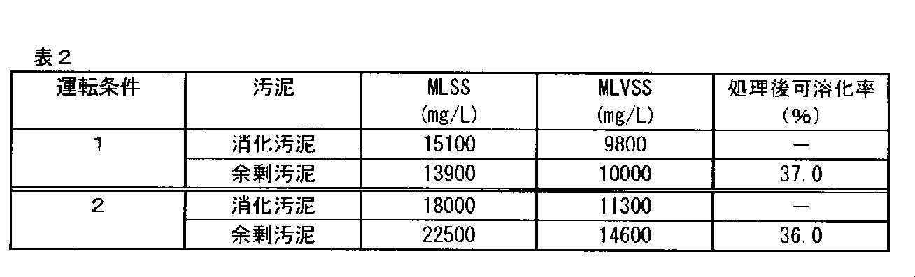
- Table 2 shows the digested sludge and substrate used in each operating condition. Every day, the digested sludge was sampled from the digestion bottle in the amount described in Table 1. After sampling, the same amount of substrate was added to the digestion bottle. The treated sludge obtained in Example 1 was used as the excess sludge after treatment with the cell wall or cell membrane crusher as a substrate. During the experiment, the digestion bottle was kept at about 36 ° C. while stirring with a stirrer. The suspended matter concentration (MLSS) and volatile suspended matter concentration (MLVSS) were measured for each sample. The results are shown in Table 3. In addition, the decreasing rate of MLSS and MLVSS in Table 3 is expressed as a relative value based on untreated sludge (Comparative Examples 2 and 3).
- FIG. 5A shows comparative data on the cumulative amount of methane gas generated
- FIG. 5B shows comparative data on the methane gas conversion rate.
- Example 3 in the operating condition 1, the MLSS and MLVSS reduction rates of the treated sludge (Example 3) increased by 1.20 times and 1.17 times, respectively. Also in the operating condition 2, the MLSS and MLVSS reduction rates of the treated sludge (Example 4) increased 1.10 times and 1.17 times, respectively. In Example 5, both the MLSS and MLVSS reduction rates were inferior to those of Comparative Example 3. The reason for this is considered to be that in the case of Example 5, the substrate load on the seed sludge was too high to be digested. As can be seen from these results, it has been clarified that the final treatment period of sludge can be shortened by 10 days or more as compared with the conventional mode in which the cell wall or cell membrane crushing apparatus is not used.
- the aerobic treatment experimental apparatus is composed of an aeration tank and a precipitation tank.
- the glucose of the input substrate which is the main carbon source, was supplied into the aeration tank so that the inflow BOD was about 200 mg / L.
- the activated sludge charged into the aeration tank was set to 20 L
- the residence time was set to 24 hours
- the MLSS in the aeration tank was set to 1,000 to 2,000 mg / L.
- the number of days for the continuous experiment was 20 days.
- the amount of sludge produced in the system of Example 6 was reduced by 62% compared to the system of Comparative Example 4. This is considered to be because the sludge treated with the cell wall or cell membrane crusher and returned to the aeration tank was efficiently biodegraded and reduced in volume.
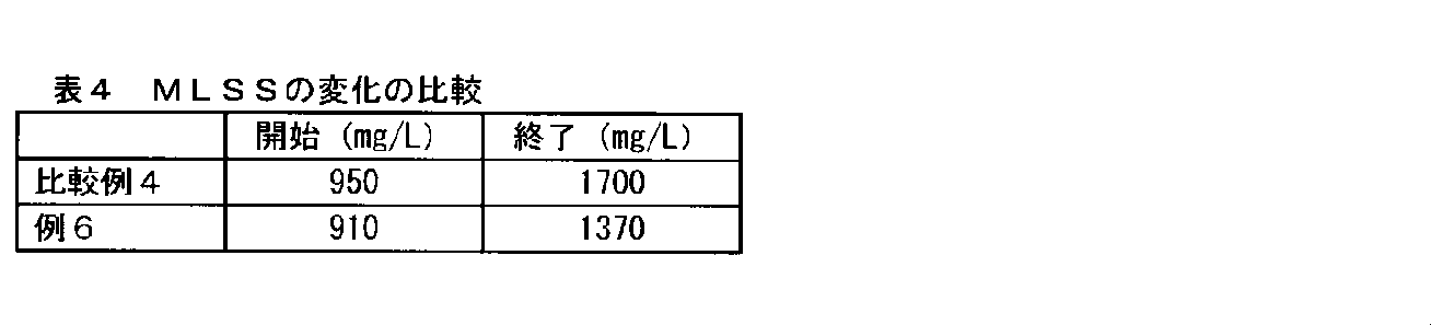
- Table 4 it was confirmed that the amount of MLSS was lower in the system of Example 6 from the start to the end than in the system of Comparative Example 4.
- Table 4 the water quality of the treated water of Example 6 is almost the same as that of Comparative Example 4, so that it was confirmed that the system of Example 6 was able to operate in a good state.
- Example 7 The cultured high-density algae culture solution was treated with a cell wall or cell membrane crusher.
- the processing conditions of the cell wall or cell membrane crusher were the same as those in Example 1 except that the processing time was changed to 10 minutes, 20 minutes, and 30 minutes.
- 100 mL of each of the crushed algae culture solution and the crushed algae culture solution was collected in a beaker, and then nanobubbles were passed through the beaker for 10 seconds to collect lipids from the algae.
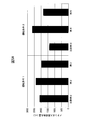
- FIG. 7A As can be seen from FIG. 7A, it was confirmed that the lipid can be efficiently recovered from the algae culture solution when the treatment time is about 20 to 30 minutes.
- the recovery process using nanobubbles is effective not only for the recovery of algae lipids but also for the recovery of oil contained in algae and microorganisms.
- the algae culture liquid (alga liquid) crushed for 30 minutes with the cell wall or cell membrane crusher was subjected to hydrogen fermentation.
- the anaerobic digestive liquid used in the sewage treatment plant was used as an inoculum for hydrogen fermentation.
- Example 7B in the system of Comparative Example 5, almost no hydrogen was generated at any mixing ratio, whereas in Example 7, the crushed algal fluid and digested bacteria were mixed at 5: 5. In addition, it was confirmed that 0.9 mL of hydrogen gas was generated per 1 g of dry alga bodies. From the above, it was confirmed that the cell wall or cell membrane crusher can contribute to the generation of hydrogen produced as a byproduct of methane fermentation.
Landscapes
- Engineering & Computer Science (AREA)
- Life Sciences & Earth Sciences (AREA)
- Chemical & Material Sciences (AREA)
- Health & Medical Sciences (AREA)
- Organic Chemistry (AREA)
- Bioinformatics & Cheminformatics (AREA)
- Wood Science & Technology (AREA)
- Zoology (AREA)
- Water Supply & Treatment (AREA)
- Environmental & Geological Engineering (AREA)
- Hydrology & Water Resources (AREA)
- Food Science & Technology (AREA)
- Biotechnology (AREA)
- Genetics & Genomics (AREA)
- Molecular Biology (AREA)
- General Health & Medical Sciences (AREA)
- General Engineering & Computer Science (AREA)
- Biochemistry (AREA)
- Microbiology (AREA)
- Biomedical Technology (AREA)
- Oil, Petroleum & Natural Gas (AREA)
- Toxicology (AREA)
- Chemical Kinetics & Catalysis (AREA)
- General Chemical & Material Sciences (AREA)
- Sustainable Development (AREA)
- Medicinal Chemistry (AREA)
- Polymers & Plastics (AREA)
- Mycology (AREA)
- Tropical Medicine & Parasitology (AREA)
- Virology (AREA)
- Mechanical Engineering (AREA)
- Nutrition Science (AREA)
- Separation Using Semi-Permeable Membranes (AREA)
- Treatment Of Sludge (AREA)
- Apparatus Associated With Microorganisms And Enzymes (AREA)
- Processing Of Solid Wastes (AREA)
- Coloring Foods And Improving Nutritive Qualities (AREA)
- Medicines Containing Material From Animals Or Micro-Organisms (AREA)
- Crushing And Grinding (AREA)
- Preparation Of Compounds By Using Micro-Organisms (AREA)
Abstract
Description
(例1)
図1の構成(但し、170を吐出口、180を投入口とし、190の減圧手段に代えて、吐出口の後段に一軸ねじ式ポンプ、及び減圧ポンプを採用した。)の細胞壁又は細胞膜破砕装置を使用して余剰汚泥を処理した。処理条件は、回転ディスクの回転数を3500min-1、周速を50m/s、減圧条件を-0.01MPa、処理時間を60分とした。下水処理の分野において一般に採用される嫌気性処理を再現するために、バイアル瓶による回分実験を採用した。嫌気性処理とは、酸素のない嫌気的条件下においてメタン菌等の微生物の代謝作用により、汚泥等に含まれる有機物を分解し、メタンガスに変換する生物学的プロセスである。
窒素ガスで内部を置換したバイアル瓶(75mL)に、消化汚泥を20mL、基質として細胞壁又は細胞膜破砕装置処理前の余剰汚泥を20mL投入し、恒温振とう槽(水温:36℃、振とう数:100回/min)に設置して経時的なメタンガス発生量を測定した。その結果を、図4A及び図4Bに示す。
(例2~例5、比較例2、比較例3)
実際の嫌気性処理は連続的に行われている。したがって、連続的な嫌気性処理のモデル実験を実施するために、消化汚泥及び基質(細胞壁又は細胞膜破砕装置処理前の余剰汚泥又は処理後の余剰汚泥)を混合して嫌気性処理を行う消化瓶と、発生ガスを水上捕集する発生ガス測定器との2つで構成される実験装置を採用した。窒素ガスで内部を置換した消化瓶(2L)に種汚泥としての消化汚泥を1.5L投入した。連続的生分解性試験における運転条件を表1に示す。また、各運転条件において使用した消化汚泥及び基質を表2に示す。1日毎に、消化瓶から消化汚泥を表1に記載される量でサンプリングした。サンプリング後にサンプリング量と同量の基質を消化瓶に添加した。基質としての細胞壁又は細胞膜破砕装置処理後の余剰汚泥は、例1で得られた処理汚泥を使用した。実験中、スターラーで撹拌しながら、消化瓶を約36℃に保持した。各サンプルについての、浮遊物質濃度(MLSS)及び揮発性浮遊物質濃度(MLVSS)を測定した。その結果を表3に示す。なお、表3中のMLSS及びMLVSSの減少率は、未処理汚泥(比較例2、3)を基準とした相対値で表している。図5Aはメタンガス累積発生量の比較データを示し、図5Bはメタンガス転換率の比較データを示している。


(例6)
好気性処理の実験装置は、曝気槽及び沈殿槽の2つで構成されている。主な炭素源である投入基質のグルコースを、流入BODで約200mg/Lとなるように曝気槽内に供給した。運転条件に関し、曝気槽内に投入した活性汚泥は20L、滞留時間は24時間、曝気槽内のMLSSは1,000~2,000mg/Lに設定した。連続実験の日数は20日間とした。この過程で生成する余剰汚泥を濃縮した後、細胞壁又は細胞膜破砕装置で処理したものを曝気槽内に返送し、余剰汚泥の発生量、並びに曝気槽内及び処理水の水質について検討した。細胞壁又は細胞膜破砕装置の処理条件は例1と同一の条件で実施した。その結果を、図6、表4及び表5に示す。なお、処理水及び曝気槽内から汚泥を1日1回サンプリングし、MLSS、SS(浮遊物質)、全有機炭素量(TOC)、生物化学的酸素要求量(BOD)、溶存有機炭素量(DOC)、全窒素量(T-N)、全リン量(T-P)の測定を実施した。
対照系として、汚泥の引き抜きを行わない通常の好気性処理を実施した。その結果を、図6、表4及び表5に示す。

(例7)
培養した高密度の藻類培養液を細胞壁又は細胞膜破砕装置で処理した。細胞壁又は細胞膜破砕装置の処理条件は、処理時間を10分、20分、30分に変更した以外は、例1と同一の条件で実施した。破砕した藻類培養液及び未破砕の藻類培養液をそれぞれビーカーに100mL採取し、次いで、該ビーカー中にナノバブルを10秒間通気して藻類からの脂質を回収した。その結果を図7Aに示す。図7Aから分かるように、処理時間が20~30分程度であると、藻類培養液から脂質を効率よく回収できることが確認された。なお、このナノバブルによる回収処理は、藻類の脂質回収に限らず、藻類や微生物等に含まれる油分の回収に対しても有効であることは、この実験より明らかである。
対照系として、未破砕の藻類培養液(藻液)を水素発酵に供した。例7と同様に、消化菌と藻液とを一定比率(消化菌:藻液=1:9、5:5、9:1)で混合し、pHを5に調整して嫌気消化を行った。その結果を図7Bに示す。
105 対象物の流れ
110 インバーター
120 モーター
130、230 回転軸
140 固定ディスク
150、250 回転ディスク
160、260 筐体
170 投入口
180 吐出口
190 減圧手段
295 クラウド
805 処理前貯留槽
815 陸上式ポンプ
825 処理後貯留槽
Claims (16)
- 固定ディスク、回転ディスク、該回転ディスクを駆動するための回転軸、減圧手段及び筐体を備える、細胞壁又は細胞膜破砕装置であって、
前記固定ディスク及び前記回転ディスクの少なくとも1組は対向して配置されており、前記固定ディスクの中心部は、該中心部を通る前記回転軸の外径よりも大きい空洞部を有し、
前記回転ディスクと前記固定ディスクとの間で発生した剪断力が、前記装置内に投入された含水率89%以上の対象物の流体に適用され、
前記細胞壁又は細胞膜破砕装置内の圧力が、前記減圧手段によって-0.08MPa以下に減圧される、細胞壁又は細胞膜破砕装置。 - 固定ディスク、回転ディスク、該回転ディスクを駆動するための回転軸、陸上式ポンプ及び/又は水中ポンプの吸引力による減圧手段及び筐体を備える、細胞壁又は細胞膜破砕装置であって、
前記固定ディスク及び前記回転ディスクの少なくとも1組は対向して配置されており、前記固定ディスクの中心部は、該中心部を通る前記回転軸の外径よりも大きい空洞部を有し、
前記回転ディスクと前記固定ディスクとの間で発生した剪断力が、前記装置内に投入された含水率89%以上の対象物の流体に適用され、
陸上式ポンプを使用する場合には、該陸上式ポンプは前記装置の吐出口以降に設置され、
水中ポンプを使用する場合には、該水中ポンプは前記装置内の最終固定ディスク以降の吐出口側に設置されている、細胞壁又は細胞膜破砕装置。 - 前記陸上式ポンプが一軸ねじ式ポンプである、請求項2記載の細胞壁又は細胞膜破砕装置。
- 前記回転ディスクは10m/s以上の周速で回転する、請求項1~3のいずれか一項に記載の細胞壁又は細胞膜破砕装置。
- 前記固定ディスク及び/又は前記回転ディスクを2つ以上備える、請求項1~4のいずれか一項に記載の細胞壁又は細胞膜破砕装置。
- 前記固定ディスクと回転ディスクとの間隙が5mm~30mmである、請求項1~5のいずれか一項に記載の細胞壁又は細胞膜破砕装置。
- 前記回転ディスク及び/又は固定ディスクの表面が鏡面又は粗面である、請求項1~6のいずれか一項に記載の細胞壁又は細胞膜破砕装置。
- 前記細胞壁又は細胞膜破砕装置に投入する対象物が、菌類、微生物、藻類、及び植物の群から選択される少なくとも1種を含む、請求項1~7のいずれか一項に記載の細胞壁又は細胞膜破砕装置。
- 前記細胞壁又は細胞膜破砕装置に投入する対象物が汚泥である、請求項1~8のいずれか一項に記載の細胞壁又は細胞膜破砕装置。
- 請求項1~9のいずれか一項に記載の細胞壁又は細胞膜破砕装置によって汚泥を処理する工程を備える、汚泥の減容化方法。
- 請求項1~9のいずれか一項に記載の細胞壁又は細胞膜破砕装置によって汚泥を処理する工程、及び前記汚泥を処理する工程から得られた処理汚泥を肥料化する工程を備える、汚泥の肥料調製方法。
- 請求項1~9のいずれか一項に記載の細胞壁又は細胞膜破砕装置によって汚泥を処理する工程、及び前記汚泥を処理する工程から得られた処理分離液を培養液として採取する工程を備える、汚泥の培養液調製方法。
- 請求項1~9のいずれか一項に記載の細胞壁又は細胞膜破砕装置によって汚水及び/若しくは汚泥、又は臭気性食品を処理する工程を備える、脱臭方法。
- 請求項1~9のいずれか一項に記載の細胞壁又は細胞膜破砕装置によって汚泥を処理する工程、並びに前記汚泥を処理する工程から得られた処理汚泥及び/又は処理分離液をバイオガス発酵槽に提供する工程を備える、バイオガスの発酵方法。
- 請求項1~8のいずれか一項に記載の細胞壁又は細胞膜破砕装置によって、菌類、微生物、藻類、及び植物の群から選択される少なくとも1種の対象物を処理する工程を備える、食品、飲料、医薬品、サプリメント類又は化粧品の製造方法。
- 請求項1~9のいずれか一項に記載の細胞壁又は細胞膜破砕装置によって、菌類、微生物、藻類、及び植物の群から選択される少なくとも1種の油分を含む対象物を処理する工程を備える、油分回収方法。
Priority Applications (6)
| Application Number | Priority Date | Filing Date | Title |
|---|---|---|---|
| KR1020187031034A KR102113940B1 (ko) | 2016-05-27 | 2016-11-24 | 세포벽 또는 세포막 파쇄 장치 및 해당 장치의 사용 방법 |
| SG11201809754WA SG11201809754WA (en) | 2016-05-27 | 2016-11-24 | Cell wall or cell membrane disrupting device, and method of using the same |
| JP2017559141A JP6279183B1 (ja) | 2016-05-27 | 2016-11-24 | 細胞壁又は細胞膜破砕装置及び該装置の使用方法 |
| CN201680086177.5A CN109196088B (zh) | 2016-05-27 | 2016-11-24 | 细胞壁或细胞膜破碎装置及该装置的使用方法 |
| EP16903211.7A EP3467092B1 (en) | 2016-05-27 | 2016-11-24 | Cell wall/cell membrane disruption device and method for using device |
| US16/304,392 US11338300B2 (en) | 2016-05-27 | 2016-11-24 | Cell wall or cell membrane disrupting device, and method of using the same |
Applications Claiming Priority (2)
| Application Number | Priority Date | Filing Date | Title |
|---|---|---|---|
| PCT/JP2016/065808 WO2017203712A1 (ja) | 2016-05-27 | 2016-05-27 | 細胞壁又は細胞膜破砕装置及び該装置の使用方法 |
| JPPCT/JP2016/065808 | 2016-05-27 |
Publications (1)
| Publication Number | Publication Date |
|---|---|
| WO2017203732A1 true WO2017203732A1 (ja) | 2017-11-30 |
Family
ID=60411180
Family Applications (2)
| Application Number | Title | Priority Date | Filing Date |
|---|---|---|---|
| PCT/JP2016/065808 Ceased WO2017203712A1 (ja) | 2016-05-27 | 2016-05-27 | 細胞壁又は細胞膜破砕装置及び該装置の使用方法 |
| PCT/JP2016/084844 Ceased WO2017203732A1 (ja) | 2016-05-27 | 2016-11-24 | 細胞壁又は細胞膜破砕装置及び該装置の使用方法 |
Family Applications Before (1)
| Application Number | Title | Priority Date | Filing Date |
|---|---|---|---|
| PCT/JP2016/065808 Ceased WO2017203712A1 (ja) | 2016-05-27 | 2016-05-27 | 細胞壁又は細胞膜破砕装置及び該装置の使用方法 |
Country Status (7)
| Country | Link |
|---|---|
| US (1) | US11338300B2 (ja) |
| EP (1) | EP3467092B1 (ja) |
| JP (1) | JP6279183B1 (ja) |
| KR (1) | KR102113940B1 (ja) |
| CN (1) | CN109196088B (ja) |
| SG (1) | SG11201809754WA (ja) |
| WO (2) | WO2017203712A1 (ja) |
Cited By (1)
| Publication number | Priority date | Publication date | Assignee | Title |
|---|---|---|---|---|
| JP7082734B1 (ja) | 2022-02-17 | 2022-06-09 | 生態環境部華南環境科学研究所 | 機械‐超音波併用に基づく汚泥細胞破砕用一体型装置 |
Families Citing this family (6)
| Publication number | Priority date | Publication date | Assignee | Title |
|---|---|---|---|---|
| CN110902756B (zh) * | 2019-11-22 | 2021-11-23 | 江苏大学 | 一种污水绿色处理装置 |
| KR102389129B1 (ko) * | 2019-12-16 | 2022-04-21 | 한국건설기술연구원 | 조류 바이오매스를 활용한 퇴비화 장치 |
| WO2022072827A1 (en) | 2020-10-02 | 2022-04-07 | Sensill, Inc. | Devices, methods, and systems to collect, store, and analyze chemical substances |
| WO2022133276A1 (en) * | 2020-12-19 | 2022-06-23 | Sensill, Inc. | Devices, methods, and systems to collect, concentrate, store, and analyze chemical substances |
| CN114436488B (zh) * | 2022-04-07 | 2022-06-17 | 生态环境部华南环境科学研究所 | 一种用于污泥细胞破解的机械转盘搅拌装置 |
| CN118080085B (zh) * | 2024-04-19 | 2024-06-21 | 佛山市奥涂凯机械设备有限公司 | 一种用于获取负离子材料的海藻植物研磨处理设备 |
Citations (10)
| Publication number | Priority date | Publication date | Assignee | Title |
|---|---|---|---|---|
| JPS5330004A (en) * | 1976-08-31 | 1978-03-20 | Nishihara Kankiyou Eisei Kenki | Submerged slurry pumps |
| JPH10230247A (ja) * | 1997-02-19 | 1998-09-02 | Mitsubishi Heavy Ind Ltd | 加圧による水中微生物の殺傷方法および装置 |
| JP2002336898A (ja) | 2001-05-15 | 2002-11-26 | Ebara Corp | 汚泥のメタン発酵処理方法と装置 |
| JP2006000802A (ja) * | 2004-06-21 | 2006-01-05 | Ebara Corp | 生物が生育する水域の水の処理方法及び装置 |
| JP3731204B2 (ja) | 2001-03-27 | 2006-01-05 | 有限会社山口ティー・エル・オー | 汚泥破砕装置及びそれを用いた有機性汚水の処理装置 |
| JP2007268515A (ja) * | 2006-03-06 | 2007-10-18 | Kenjiro Makino | 天然物の超微粉砕物の製造方法、該製造方法で得られた天然物の超微粉砕物および該製造方法に用いる装置 |
| JP2011234676A (ja) * | 2010-05-11 | 2011-11-24 | Trance Energy Kk | 微細藻類を利用した生物燃料の製造方法 |
| JP2012254426A (ja) * | 2011-06-10 | 2012-12-27 | Tsukishima Kikai Co Ltd | バイオマスのメタン発酵装置 |
| JP2013133242A (ja) * | 2011-12-26 | 2013-07-08 | Fuji Koki Kk | 液体肥料の製造方法 |
| WO2013176261A1 (ja) * | 2012-05-25 | 2013-11-28 | 味の素株式会社 | 微細藻類を用いた栄養添加剤の製造法 |
Family Cites Families (11)
| Publication number | Priority date | Publication date | Assignee | Title |
|---|---|---|---|---|
| US4038433A (en) * | 1975-07-29 | 1977-07-26 | Gebrueder Buehler Ag | Method for processing soft vegetable foodstuffs into crumbs |
| US4684072A (en) * | 1986-05-19 | 1987-08-04 | Epworth Manufacturing Co., Inc. | Blade for centrifugal media mill |
| DE4128074C2 (de) * | 1991-08-23 | 1995-06-29 | Omya Gmbh | Rührwerkskugelmühle |
| SE469417B (sv) * | 1991-12-20 | 1993-07-05 | Sala International Ab | Saett och anordning foer finmalning av foer filleraendamaal anvaendbara mineral i torrt tillstaand |
| CH688849A5 (de) * | 1993-02-25 | 1998-04-30 | Buehler Ag | Ruehrwerksmuehle. |
| US6059971A (en) | 1995-01-30 | 2000-05-09 | Vit; Robert | Device and process for thickening and conveying waste water sludge |
| JP2000343098A (ja) | 1999-06-07 | 2000-12-12 | Shin Meiwa Ind Co Ltd | 汚泥破砕装置及び有機性汚水の処理装置 |
| JP2006334489A (ja) | 2005-06-01 | 2006-12-14 | Sasaki Corporation | 生物系物質の破砕成分抽出装置 |
| KR100814405B1 (ko) * | 2007-04-10 | 2008-03-18 | 이순화 | 슬러지 파쇄장치 |
| PL2465610T3 (pl) * | 2010-12-20 | 2013-09-30 | Podwysocki Spolka Jawna | Urządzenie i sposób dezintegracji ścieków |
| CN105105082A (zh) * | 2015-07-23 | 2015-12-02 | 潍坊友容实业有限公司 | 一种盐地碱蓬植物盐提取中真空负压破壁设备 |
-
2016
- 2016-05-27 WO PCT/JP2016/065808 patent/WO2017203712A1/ja not_active Ceased
- 2016-11-24 JP JP2017559141A patent/JP6279183B1/ja active Active
- 2016-11-24 WO PCT/JP2016/084844 patent/WO2017203732A1/ja not_active Ceased
- 2016-11-24 KR KR1020187031034A patent/KR102113940B1/ko active Active
- 2016-11-24 US US16/304,392 patent/US11338300B2/en active Active
- 2016-11-24 CN CN201680086177.5A patent/CN109196088B/zh active Active
- 2016-11-24 SG SG11201809754WA patent/SG11201809754WA/en unknown
- 2016-11-24 EP EP16903211.7A patent/EP3467092B1/en active Active
Patent Citations (10)
| Publication number | Priority date | Publication date | Assignee | Title |
|---|---|---|---|---|
| JPS5330004A (en) * | 1976-08-31 | 1978-03-20 | Nishihara Kankiyou Eisei Kenki | Submerged slurry pumps |
| JPH10230247A (ja) * | 1997-02-19 | 1998-09-02 | Mitsubishi Heavy Ind Ltd | 加圧による水中微生物の殺傷方法および装置 |
| JP3731204B2 (ja) | 2001-03-27 | 2006-01-05 | 有限会社山口ティー・エル・オー | 汚泥破砕装置及びそれを用いた有機性汚水の処理装置 |
| JP2002336898A (ja) | 2001-05-15 | 2002-11-26 | Ebara Corp | 汚泥のメタン発酵処理方法と装置 |
| JP2006000802A (ja) * | 2004-06-21 | 2006-01-05 | Ebara Corp | 生物が生育する水域の水の処理方法及び装置 |
| JP2007268515A (ja) * | 2006-03-06 | 2007-10-18 | Kenjiro Makino | 天然物の超微粉砕物の製造方法、該製造方法で得られた天然物の超微粉砕物および該製造方法に用いる装置 |
| JP2011234676A (ja) * | 2010-05-11 | 2011-11-24 | Trance Energy Kk | 微細藻類を利用した生物燃料の製造方法 |
| JP2012254426A (ja) * | 2011-06-10 | 2012-12-27 | Tsukishima Kikai Co Ltd | バイオマスのメタン発酵装置 |
| JP2013133242A (ja) * | 2011-12-26 | 2013-07-08 | Fuji Koki Kk | 液体肥料の製造方法 |
| WO2013176261A1 (ja) * | 2012-05-25 | 2013-11-28 | 味の素株式会社 | 微細藻類を用いた栄養添加剤の製造法 |
Non-Patent Citations (1)
| Title |
|---|
| See also references of EP3467092A4 |
Cited By (2)
| Publication number | Priority date | Publication date | Assignee | Title |
|---|---|---|---|---|
| JP7082734B1 (ja) | 2022-02-17 | 2022-06-09 | 生態環境部華南環境科学研究所 | 機械‐超音波併用に基づく汚泥細胞破砕用一体型装置 |
| JP2023120123A (ja) * | 2022-02-17 | 2023-08-29 | 生態環境部華南環境科学研究所 | 機械‐超音波併用に基づく汚泥細胞破砕用一体型装置 |
Also Published As
| Publication number | Publication date |
|---|---|
| US20190217307A1 (en) | 2019-07-18 |
| SG11201809754WA (en) | 2018-12-28 |
| EP3467092B1 (en) | 2021-06-23 |
| EP3467092A4 (en) | 2020-04-29 |
| WO2017203712A1 (ja) | 2017-11-30 |
| CN109196088A (zh) | 2019-01-11 |
| US11338300B2 (en) | 2022-05-24 |
| JP6279183B1 (ja) | 2018-02-14 |
| EP3467092A1 (en) | 2019-04-10 |
| KR102113940B1 (ko) | 2020-05-21 |
| CN109196088B (zh) | 2020-05-22 |
| JPWO2017203732A1 (ja) | 2018-06-07 |
| KR20180128465A (ko) | 2018-12-03 |
Similar Documents
| Publication | Publication Date | Title |
|---|---|---|
| JP6279183B1 (ja) | 細胞壁又は細胞膜破砕装置及び該装置の使用方法 | |
| Kwiatkowska et al. | Stimulation of bioprocesses by ultrasound | |
| CA2211721C (en) | Device and process for thickening and conveying waste water sludges | |
| Save et al. | Use of hydrodynamic cavitation for large scale microbial cell disruption | |
| JP2013507126A (ja) | 藻類の処理 | |
| US20180087019A1 (en) | Microorganism growth and products recovery | |
| KR102061904B1 (ko) | 파쇄 및 확산형 교반장치 | |
| WO2017030592A1 (en) | System and process for recovering algal oil | |
| JP6271787B1 (ja) | バイオガスを生成する汚泥処理システム | |
| US20160177253A1 (en) | Method and system for preparation of substrate for use in anaerobic digestion of organic waste | |
| Nykyforov et al. | DEVELOPING A TECHNOLOGY FOR TREATING BLUE-GREEN ALGAE BIOMASS USING VIBRO-RESONANCE CAVITATORS. | |
| KR101317490B1 (ko) | 농축·가용화 조합을 통한 분리막 수처리 잉여슬러지의 고효율 바이오가스 생성 시스템 및 그 방법 | |
| Neis et al. | Ultrasonic disintegration of sewage sludge for enhanced anaerobic biodegradation | |
| Pell et al. | Mild disintegration methods of microalgae–bacteria flocs from wastewater treatment | |
| JP3731204B2 (ja) | 汚泥破砕装置及びそれを用いた有機性汚水の処理装置 | |
| JP6271782B1 (ja) | 原水の濁度及びbod濃度を低減する方法、及び該方法に使用する加圧汚泥固形化濃縮機 | |
| WO2009071878A1 (en) | Production of volatile fatty acids by means of mesophilic fermentation of sludge | |
| JP4726478B2 (ja) | 流動物の超微細化装置 | |
| JP2005169240A (ja) | 汚水処理設備 | |
| RU2841780C1 (ru) | Биореактор для переработки жидких органических отходов на биогумус и биогаз | |
| KR101266655B1 (ko) | 슬러지 가용화를 위한 슬러지 파쇄장치 | |
| JP2008238078A (ja) | メタン発酵処理方法および装置 | |
| JP7432910B2 (ja) | メタン生成システム及びメタン生成方法 | |
| Agrawal | Fermentor | |
| EP3279309B1 (en) | Plant for treating biomass |
Legal Events
| Date | Code | Title | Description |
|---|---|---|---|
| ENP | Entry into the national phase |
Ref document number: 2017559141 Country of ref document: JP Kind code of ref document: A |
|
| ENP | Entry into the national phase |
Ref document number: 20187031034 Country of ref document: KR Kind code of ref document: A |
|
| 121 | Ep: the epo has been informed by wipo that ep was designated in this application |
Ref document number: 16903211 Country of ref document: EP Kind code of ref document: A1 |
|
| NENP | Non-entry into the national phase |
Ref country code: DE |
|
| ENP | Entry into the national phase |
Ref document number: 2016903211 Country of ref document: EP Effective date: 20190102 |