WO2017203761A1 - Enveloppe étanche à l'air, et procédé de fabrication de celle-ci - Google Patents
Enveloppe étanche à l'air, et procédé de fabrication de celle-ci Download PDFInfo
- Publication number
- WO2017203761A1 WO2017203761A1 PCT/JP2017/005702 JP2017005702W WO2017203761A1 WO 2017203761 A1 WO2017203761 A1 WO 2017203761A1 JP 2017005702 W JP2017005702 W JP 2017005702W WO 2017203761 A1 WO2017203761 A1 WO 2017203761A1
- Authority
- WO
- WIPO (PCT)
- Prior art keywords
- sealing material
- glass
- irradiation
- container
- glass lid
- Prior art date
- Legal status (The legal status is an assumption and is not a legal conclusion. Google has not performed a legal analysis and makes no representation as to the accuracy of the status listed.)
- Ceased
Links
Images


Classifications
-
- H—ELECTRICITY
- H10—SEMICONDUCTOR DEVICES; ELECTRIC SOLID-STATE DEVICES NOT OTHERWISE PROVIDED FOR
- H10W—GENERIC PACKAGES, INTERCONNECTIONS, CONNECTORS OR OTHER CONSTRUCTIONAL DETAILS OF DEVICES COVERED BY CLASS H10
- H10W76/00—Containers; Fillings or auxiliary members therefor; Seals
- H10W76/60—Seals
-
- B—PERFORMING OPERATIONS; TRANSPORTING
- B23—MACHINE TOOLS; METAL-WORKING NOT OTHERWISE PROVIDED FOR
- B23K—SOLDERING OR UNSOLDERING; WELDING; CLADDING OR PLATING BY SOLDERING OR WELDING; CUTTING BY APPLYING HEAT LOCALLY, e.g. FLAME CUTTING; WORKING BY LASER BEAM
- B23K26/00—Working by laser beam, e.g. welding, cutting or boring
- B23K26/08—Devices involving relative movement between laser beam and workpiece
- B23K26/082—Scanning systems, i.e. devices involving movement of the laser beam relative to the laser head
-
- B—PERFORMING OPERATIONS; TRANSPORTING
- B23—MACHINE TOOLS; METAL-WORKING NOT OTHERWISE PROVIDED FOR
- B23K—SOLDERING OR UNSOLDERING; WELDING; CLADDING OR PLATING BY SOLDERING OR WELDING; CUTTING BY APPLYING HEAT LOCALLY, e.g. FLAME CUTTING; WORKING BY LASER BEAM
- B23K26/00—Working by laser beam, e.g. welding, cutting or boring
- B23K26/08—Devices involving relative movement between laser beam and workpiece
- B23K26/083—Devices involving movement of the workpiece in at least one axial direction
- B23K26/0853—Devices involving movement of the workpiece in at least two axial directions, e.g. in a plane
-
- B—PERFORMING OPERATIONS; TRANSPORTING
- B23—MACHINE TOOLS; METAL-WORKING NOT OTHERWISE PROVIDED FOR
- B23K—SOLDERING OR UNSOLDERING; WELDING; CLADDING OR PLATING BY SOLDERING OR WELDING; CUTTING BY APPLYING HEAT LOCALLY, e.g. FLAME CUTTING; WORKING BY LASER BEAM
- B23K26/00—Working by laser beam, e.g. welding, cutting or boring
- B23K26/20—Bonding
- B23K26/206—Laser sealing
-
- B—PERFORMING OPERATIONS; TRANSPORTING
- B23—MACHINE TOOLS; METAL-WORKING NOT OTHERWISE PROVIDED FOR
- B23K—SOLDERING OR UNSOLDERING; WELDING; CLADDING OR PLATING BY SOLDERING OR WELDING; CUTTING BY APPLYING HEAT LOCALLY, e.g. FLAME CUTTING; WORKING BY LASER BEAM
- B23K26/00—Working by laser beam, e.g. welding, cutting or boring
- B23K26/20—Bonding
- B23K26/21—Bonding by welding
- B23K26/211—Bonding by welding with interposition of special material to facilitate connection of the parts
-
- B—PERFORMING OPERATIONS; TRANSPORTING
- B23—MACHINE TOOLS; METAL-WORKING NOT OTHERWISE PROVIDED FOR
- B23K—SOLDERING OR UNSOLDERING; WELDING; CLADDING OR PLATING BY SOLDERING OR WELDING; CUTTING BY APPLYING HEAT LOCALLY, e.g. FLAME CUTTING; WORKING BY LASER BEAM
- B23K26/00—Working by laser beam, e.g. welding, cutting or boring
- B23K26/20—Bonding
- B23K26/21—Bonding by welding
- B23K26/24—Seam welding
- B23K26/28—Seam welding of curved planar seams
-
- B—PERFORMING OPERATIONS; TRANSPORTING
- B23—MACHINE TOOLS; METAL-WORKING NOT OTHERWISE PROVIDED FOR
- B23K—SOLDERING OR UNSOLDERING; WELDING; CLADDING OR PLATING BY SOLDERING OR WELDING; CUTTING BY APPLYING HEAT LOCALLY, e.g. FLAME CUTTING; WORKING BY LASER BEAM
- B23K26/00—Working by laser beam, e.g. welding, cutting or boring
- B23K26/20—Bonding
- B23K26/32—Bonding taking account of the properties of the material involved
- B23K26/324—Bonding taking account of the properties of the material involved involving non-metallic parts
-
- C—CHEMISTRY; METALLURGY
- C03—GLASS; MINERAL OR SLAG WOOL
- C03C—CHEMICAL COMPOSITION OF GLASSES, GLAZES OR VITREOUS ENAMELS; SURFACE TREATMENT OF GLASS; SURFACE TREATMENT OF FIBRES OR FILAMENTS MADE FROM GLASS, MINERALS OR SLAGS; JOINING GLASS TO GLASS OR OTHER MATERIALS
- C03C23/00—Other surface treatment of glass not in the form of fibres or filaments
- C03C23/0005—Other surface treatment of glass not in the form of fibres or filaments by irradiation
- C03C23/0025—Other surface treatment of glass not in the form of fibres or filaments by irradiation by a laser beam
-
- C—CHEMISTRY; METALLURGY
- C03—GLASS; MINERAL OR SLAG WOOL
- C03C—CHEMICAL COMPOSITION OF GLASSES, GLAZES OR VITREOUS ENAMELS; SURFACE TREATMENT OF GLASS; SURFACE TREATMENT OF FIBRES OR FILAMENTS MADE FROM GLASS, MINERALS OR SLAGS; JOINING GLASS TO GLASS OR OTHER MATERIALS
- C03C27/00—Joining pieces of glass to pieces of other inorganic material; Joining glass to glass other than by fusing
- C03C27/06—Joining glass to glass by processes other than fusing
-
- C—CHEMISTRY; METALLURGY
- C03—GLASS; MINERAL OR SLAG WOOL
- C03C—CHEMICAL COMPOSITION OF GLASSES, GLAZES OR VITREOUS ENAMELS; SURFACE TREATMENT OF GLASS; SURFACE TREATMENT OF FIBRES OR FILAMENTS MADE FROM GLASS, MINERALS OR SLAGS; JOINING GLASS TO GLASS OR OTHER MATERIALS
- C03C27/00—Joining pieces of glass to pieces of other inorganic material; Joining glass to glass other than by fusing
- C03C27/06—Joining glass to glass by processes other than fusing
- C03C27/10—Joining glass to glass by processes other than fusing with the aid of adhesive specially adapted for that purpose
-
- C—CHEMISTRY; METALLURGY
- C03—GLASS; MINERAL OR SLAG WOOL
- C03C—CHEMICAL COMPOSITION OF GLASSES, GLAZES OR VITREOUS ENAMELS; SURFACE TREATMENT OF GLASS; SURFACE TREATMENT OF FIBRES OR FILAMENTS MADE FROM GLASS, MINERALS OR SLAGS; JOINING GLASS TO GLASS OR OTHER MATERIALS
- C03C8/00—Enamels; Glazes; Fusion seal compositions being frit compositions having non-frit additions
- C03C8/14—Glass frit mixtures having non-frit additions, e.g. opacifiers, colorants, mill-additions
-
- C—CHEMISTRY; METALLURGY
- C03—GLASS; MINERAL OR SLAG WOOL
- C03C—CHEMICAL COMPOSITION OF GLASSES, GLAZES OR VITREOUS ENAMELS; SURFACE TREATMENT OF GLASS; SURFACE TREATMENT OF FIBRES OR FILAMENTS MADE FROM GLASS, MINERALS OR SLAGS; JOINING GLASS TO GLASS OR OTHER MATERIALS
- C03C8/00—Enamels; Glazes; Fusion seal compositions being frit compositions having non-frit additions
- C03C8/14—Glass frit mixtures having non-frit additions, e.g. opacifiers, colorants, mill-additions
- C03C8/20—Glass frit mixtures having non-frit additions, e.g. opacifiers, colorants, mill-additions containing titanium compounds; containing zirconium compounds
-
- C—CHEMISTRY; METALLURGY
- C03—GLASS; MINERAL OR SLAG WOOL
- C03C—CHEMICAL COMPOSITION OF GLASSES, GLAZES OR VITREOUS ENAMELS; SURFACE TREATMENT OF GLASS; SURFACE TREATMENT OF FIBRES OR FILAMENTS MADE FROM GLASS, MINERALS OR SLAGS; JOINING GLASS TO GLASS OR OTHER MATERIALS
- C03C8/00—Enamels; Glazes; Fusion seal compositions being frit compositions having non-frit additions
- C03C8/24—Fusion seal compositions being frit compositions having non-frit additions, i.e. for use as seals between dissimilar materials, e.g. glass and metal; Glass solders
-
- H—ELECTRICITY
- H10—SEMICONDUCTOR DEVICES; ELECTRIC SOLID-STATE DEVICES NOT OTHERWISE PROVIDED FOR
- H10H—INORGANIC LIGHT-EMITTING SEMICONDUCTOR DEVICES HAVING POTENTIAL BARRIERS
- H10H20/00—Individual inorganic light-emitting semiconductor devices having potential barriers, e.g. light-emitting diodes [LED]
- H10H20/80—Constructional details
- H10H20/85—Packages
- H10H20/852—Encapsulations
- H10H20/854—Encapsulations characterised by their material, e.g. epoxy or silicone resins
-
- H—ELECTRICITY
- H10—SEMICONDUCTOR DEVICES; ELECTRIC SOLID-STATE DEVICES NOT OTHERWISE PROVIDED FOR
- H10W—GENERIC PACKAGES, INTERCONNECTIONS, CONNECTORS OR OTHER CONSTRUCTIONAL DETAILS OF DEVICES COVERED BY CLASS H10
- H10W74/00—Encapsulations, e.g. protective coatings
- H10W74/10—Encapsulations, e.g. protective coatings characterised by their shape or disposition
-
- H—ELECTRICITY
- H10—SEMICONDUCTOR DEVICES; ELECTRIC SOLID-STATE DEVICES NOT OTHERWISE PROVIDED FOR
- H10W—GENERIC PACKAGES, INTERCONNECTIONS, CONNECTORS OR OTHER CONSTRUCTIONAL DETAILS OF DEVICES COVERED BY CLASS H10
- H10W74/00—Encapsulations, e.g. protective coatings
- H10W74/40—Encapsulations, e.g. protective coatings characterised by their materials
- H10W74/43—Encapsulations, e.g. protective coatings characterised by their materials comprising oxides, nitrides or carbides, e.g. ceramics or glasses
-
- H—ELECTRICITY
- H10—SEMICONDUCTOR DEVICES; ELECTRIC SOLID-STATE DEVICES NOT OTHERWISE PROVIDED FOR
- H10W—GENERIC PACKAGES, INTERCONNECTIONS, CONNECTORS OR OTHER CONSTRUCTIONAL DETAILS OF DEVICES COVERED BY CLASS H10
- H10W76/00—Containers; Fillings or auxiliary members therefor; Seals
- H10W76/10—Containers or parts thereof
-
- H—ELECTRICITY
- H10—SEMICONDUCTOR DEVICES; ELECTRIC SOLID-STATE DEVICES NOT OTHERWISE PROVIDED FOR
- H10W—GENERIC PACKAGES, INTERCONNECTIONS, CONNECTORS OR OTHER CONSTRUCTIONAL DETAILS OF DEVICES COVERED BY CLASS H10
- H10W76/00—Containers; Fillings or auxiliary members therefor; Seals
- H10W76/10—Containers or parts thereof
- H10W76/17—Containers or parts thereof characterised by their materials
- H10W76/18—Insulating materials, e.g. resins, glasses or ceramics
-
- H—ELECTRICITY
- H10—SEMICONDUCTOR DEVICES; ELECTRIC SOLID-STATE DEVICES NOT OTHERWISE PROVIDED FOR
- H10W—GENERIC PACKAGES, INTERCONNECTIONS, CONNECTORS OR OTHER CONSTRUCTIONAL DETAILS OF DEVICES COVERED BY CLASS H10
- H10W95/00—Packaging processes not covered by the other groups of this subclass
-
- B—PERFORMING OPERATIONS; TRANSPORTING
- B23—MACHINE TOOLS; METAL-WORKING NOT OTHERWISE PROVIDED FOR
- B23K—SOLDERING OR UNSOLDERING; WELDING; CLADDING OR PLATING BY SOLDERING OR WELDING; CUTTING BY APPLYING HEAT LOCALLY, e.g. FLAME CUTTING; WORKING BY LASER BEAM
- B23K2101/00—Articles made by soldering, welding or cutting
- B23K2101/36—Electric or electronic devices
-
- B—PERFORMING OPERATIONS; TRANSPORTING
- B23—MACHINE TOOLS; METAL-WORKING NOT OTHERWISE PROVIDED FOR
- B23K—SOLDERING OR UNSOLDERING; WELDING; CLADDING OR PLATING BY SOLDERING OR WELDING; CUTTING BY APPLYING HEAT LOCALLY, e.g. FLAME CUTTING; WORKING BY LASER BEAM
- B23K2103/00—Materials to be soldered, welded or cut
- B23K2103/18—Dissimilar materials
-
- B—PERFORMING OPERATIONS; TRANSPORTING
- B23—MACHINE TOOLS; METAL-WORKING NOT OTHERWISE PROVIDED FOR
- B23K—SOLDERING OR UNSOLDERING; WELDING; CLADDING OR PLATING BY SOLDERING OR WELDING; CUTTING BY APPLYING HEAT LOCALLY, e.g. FLAME CUTTING; WORKING BY LASER BEAM
- B23K2103/00—Materials to be soldered, welded or cut
- B23K2103/50—Inorganic materials other than metals or composite materials
- B23K2103/52—Ceramics
-
- B—PERFORMING OPERATIONS; TRANSPORTING
- B23—MACHINE TOOLS; METAL-WORKING NOT OTHERWISE PROVIDED FOR
- B23K—SOLDERING OR UNSOLDERING; WELDING; CLADDING OR PLATING BY SOLDERING OR WELDING; CUTTING BY APPLYING HEAT LOCALLY, e.g. FLAME CUTTING; WORKING BY LASER BEAM
- B23K2103/00—Materials to be soldered, welded or cut
- B23K2103/50—Inorganic materials other than metals or composite materials
- B23K2103/54—Glass
Definitions
- the present invention relates to a method for manufacturing an airtight package for mounting and sealing an element, and an airtight package.
- an airtight package is used for mounting and sealing an element such as an LED.
- Such an airtight package is configured by joining a container in which an element can be mounted and a cover member for sealing the inside of the container.
- Patent Document 1 discloses an airtight package in which a glass ceramic substrate and a glass lid are joined via a sealing material.
- a glass frit made of low-melting glass is used as the sealing material.
- substrate and the glass cover are joined by baking and melting the said glass frit.
- the present inventors have found that when the thickness of the glass lid is increased, the temperature difference inside the glass lid increases due to heating by laser irradiation, and cracks are generated in the glass lid due to thermal stress.
- An object of the present invention is to provide an airtight package manufacturing method and an airtight package that can reduce the thermal stress generated in the glass lid by laser light irradiation and suppress the occurrence of cracks in the glass lid. is there.
- the manufacturing method of the present invention is a method of manufacturing an airtight package in which a container in which an element is mounted is sealed with a glass lid, the step of mounting the element inside the container, the frame of the container, and the glass lid Place the sealing material between the two, place the glass lid on the frame part of the container, and heat the sealing material by irradiating the laser light from the glass lid side while scanning the laser light along the frame part Melting and forming a sealing material layer, and sealing the glass lid and the frame portion with the sealing material layer, starting the irradiation of the laser beam from the irradiation start position, and then scanning the laser beam It is characterized in that it circulates a plurality of times on the frame part and ends the irradiation of the laser light at the irradiation end position located on the scanning direction side from the irradiation start position.
- the distance between the irradiation start position and the irradiation end position is preferably equal to or greater than the radius of the laser beam irradiation spot.
- the width of the sealing material in the direction substantially perpendicular to the scanning direction is preferably 90% or less of the width of the laser beam irradiation spot.
- the container is preferably made of ceramic, glass ceramic, or glass.
- the sealing material is preferably composed of glass frit.
- the sealing material is at least one selected from cordierite, willemite, alumina, zirconium phosphate compounds, zircon, zirconia, tin oxide, quartz glass, ⁇ -quartz solid solution, ⁇ -eucryptite, and spodumene. It preferably contains a low expansion refractory filler.
- the sealing material preferably contains a laser absorber made of at least one selected from Cu-based oxides, Fe-based oxides, Cr-based oxides, Mn-based oxides, and composite oxides thereof.
- the hermetic package of the present invention includes an element having an upper limit temperature of 350 ° C. or less, a container in which the element is mounted, a glass lid having a thickness exceeding 0.2 mm, and sealing the container, And a sealing material layer disposed between the stopper and the glass lid, wherein the sealing material layer is made of glass containing a laser absorbing material.
- the sealing material layer is at least one selected from cordierite, willemite, alumina, zirconium phosphate compounds, zircon, zirconia, tin oxide, quartz glass, ⁇ -quartz solid solution, ⁇ -eucryptite, and spodumene. It preferably contains a low expansion refractory filler.
- the element is, for example, a MEMS or a deep ultraviolet LED.
- the production method of the present invention it is possible to reduce the thermal stress generated inside the glass lid by the irradiation of laser light, and to suppress the occurrence of cracks in the glass lid.
- the hermetic package of the present invention has excellent hermeticity and package strength.
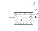
- FIG. 1 is a schematic cross-sectional view showing an airtight package according to an embodiment of the present invention.
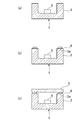
- FIG. 2 is a schematic cross-sectional view for explaining a process for manufacturing the hermetic package shown in FIG.
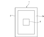
- FIG. 3 is a schematic plan view for explaining a manufacturing process of the hermetic package shown in FIG.
- FIG. 4 is a schematic plan view for explaining a manufacturing process of the hermetic package shown in FIG.
- FIG. 5 is a schematic cross-sectional view showing a state in which the sealing material is irradiated with laser light.
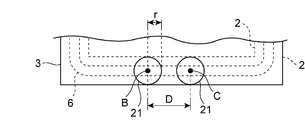
- FIG. 6 is a schematic plan view for explaining the irradiation start position and the irradiation end position of the laser beam in the present embodiment.
- FIG. 7 is a schematic plan view showing a laser beam irradiation start position and an irradiation end position in an enlarged manner.
- FIG. 1 is a schematic cross-sectional view showing an airtight package according to an embodiment of the present invention.
- an airtight package 10 of this embodiment includes a container 1 in which an element 5 is mounted, a glass lid 3 that seals the container 1, a frame portion 2 of the container 1, and a glass lid 3. And a sealing material layer 4 disposed therebetween. By bonding the upper surface 2a of the frame portion 2 and the glass lid 3 with the sealing material layer 4, the container 1 is sealed with the glass lid 3 to form an airtight structure.
- Examples of the glass constituting the glass lid 3 include SiO 2 —B 2 O 3 —RO (R is Mg, Ca, Sr or Ba) -based glass, SiO 2 —B 2 O 3 —R ′ 2 O (R ′ Is Li, Na or Ka) glass, SiO 2 —B 2 O 3 —RO—R ′ 2 O glass, SnO—P 2 O 5 glass, TeO 2 glass, Bi 2 O 3 glass, or the like. be able to.
- the thickness of the glass lid 3 is not particularly limited in the present invention, but generally, a thickness within the range of 0.01 mm to 2.0 mm is used. If the thickness of the glass lid 3 exceeds 0.2 mm, the thermal stress in laser irradiation increases and cracks are likely to occur. Therefore, when the thickness of the glass lid 3 exceeds 0.2 mm, the effect of the present invention is more easily exhibited. Moreover, package strength can be raised because the glass cover 3 has thickness exceeding 0.2 mm.
- the thickness of the glass lid 3 is more preferably 0.3 mm or more, and more preferably 0.4 mm or more.
- the container 1 is made of, for example, ceramic, glass ceramic, or glass.
- the ceramic include aluminum oxide, aluminum nitride, zirconia, and mullite.
- the glass ceramic include LTCC (Low Temperature Co-fired Ceramics).
- LTCC Low Temperature Co-fired Ceramics
- Specific examples of LTCC include a sintered body of an inorganic powder such as titanium oxide or niobium oxide and a glass powder.
- the glass powder for example, the same glass as the glass lid 3 can be used.
- the sealing material 6 for forming the sealing material layer 4 it is preferable to use a glass frit containing a low-melting glass powder.
- the low melting point glass powder for example, Bi 2 O 3 glass powder, SnO—P 2 O 5 glass powder, V 2 O 5 —TeO 2 glass powder, or the like can be used.
- at least one pigment selected from CuO, Cr 2 O 3 , Fe 2 O 3 , MnO 2 and the like may be contained in the glass.
- the sealing material may contain a low expansion refractory filler, a laser light absorbing material and the like in addition to the low melting point glass powder.
- the low expansion refractory filler include cordierite, willemite, alumina, zirconium phosphate compounds, zircon, zirconia, tin oxide, quartz glass, ⁇ -quartz solid solution, ⁇ -eucryptite, and spodumene.
- the laser light absorbing material include compounds such as at least one metal selected from Cu, Fe, Cr, Mn, and the like or an oxide containing the metal.
- the laser light absorbing material is particularly preferably composed of at least one selected from Cu-based oxides, Fe-based oxides, Cr-based oxides, Mn-based oxides, and composite oxides thereof.
- the element 5 is not particularly limited in the present invention, but according to the manufacturing method of the present invention, even if it is an element having low heat resistance, thermal deterioration during packaging can be suppressed. When an element having a low use upper limit temperature is used, the effect of the present invention is more easily exhibited. In addition, according to the present invention, even if the thickness of the glass lid 3 is increased in order to increase the strength of the hermetic package 10, a highly airtight packaging can be obtained. For this reason, when an element requiring high strength and airtightness is used, the effect of the present invention is more easily exhibited. Therefore, the effect of the present invention is more easily exhibited when the element 5 is an element that has a low use upper limit temperature and requires high airtightness. Examples of such elements include MEMS (Micro Electro Mechanical Systems), deep ultraviolet LEDs (Light Emitting Diode), and the like.
- MEMS Micro Electro Mechanical Systems
- LEDs Light Emitting Diode
- the above-mentioned MEMS and deep ultraviolet LED can be cited as an element having a use upper limit temperature of 350 ° C. or lower.
- the use upper limit temperature of the element is a temperature defined as a standard for each element, and is also referred to as an operation upper limit temperature, a maximum use temperature, or the like.
- the element 5 is not limited to the above, and other than the above, a light emitting element such as an LED, LD (Laser Diode), a light receiving element such as a CCD (Charge Coupled Device), and other elements may also be used. Can do.
- a light emitting element such as an LED, LD (Laser Diode), a light receiving element such as a CCD (Charge Coupled Device), and other elements may also be used. Can do.
- FIG. 2 is a schematic cross-sectional view for explaining a process of manufacturing the hermetic package shown in FIG.
- the element 5 is mounted inside the container 1 as shown in FIG.
- FIG. 3 is a schematic plan view for explaining a manufacturing process of the hermetic package shown in FIG.
- the frame part 2 has a rectangular shape.
- FIG. 4 is a schematic plan view for explaining a manufacturing process of the hermetic package shown in FIG. As shown in FIG. 4, the sealing material 6 is applied on the upper surface 2 a of the frame part 2 along the shape of the frame part 2.
- the glass lid 3 is placed on the frame portion 2 to which the sealing material 6 has been applied. Thereby, the sealing material 6 can be arrange
- FIG. 5 is a schematic cross-sectional view showing a state in which the sealing material is irradiated with laser light.
- the sealing material 6 disposed between the upper surface 2 a of the frame 2 and the glass lid 3 is irradiated with a laser beam 20 to heat and melt the sealing material 6.
- the sealing material 6 is heated and melted while scanning the irradiation spot 21 of the laser light 20 along the frame portion 2 in the scanning direction A.
- the width W of the sealing material 6 in the direction substantially perpendicular to the scanning direction A is preferably 90% or less of the width d of the irradiation spot 21 of the laser light 20, and is preferably in the range of 10% to 80%. More preferred. Thereby, the sealing material 6 can be heated and melted uniformly in the width direction.
- FIG. 6 is a schematic plan view for explaining the irradiation start position and the irradiation end position of the laser light in the present embodiment.
- the laser beam irradiation is started from the irradiation start position B, and then the laser beam is scanned in the scanning direction A along the frame portion 2, and the laser beam is irradiated on the frame portion 2 a predetermined number of times more than once.
- the laser beam irradiation is terminated at the irradiation end position C.
- the irradiation end position C is located closer to the scanning direction A than the irradiation start position B. Therefore, between the irradiation start position B and the irradiation end position C, the laser beam is irradiated once more than the predetermined number of times.
- the laser beam is circulated a predetermined number of times more than once on the frame 2. Therefore, what is necessary is just to heat-melt the sealing material 6 by irradiating the same location on the frame part 2 several times or more with a laser beam. Therefore, compared with the case where the sealing material 6 is heated and melted by one laser beam irradiation, the laser beam can be irradiated with a lower output. Therefore, the temperature difference which arises in the inside of the glass cover 3 by irradiation of a laser beam can be made small. Therefore, according to this embodiment, the temperature difference inside the glass lid 3 can be reduced, the thermal stress generated inside the glass lid 3 can be reduced, and the occurrence of cracks or the like in the glass lid 3 can be suppressed.
- the number of times the laser light is circulated is It is preferably 3 times or more, more preferably 10 times or more. However, if the number of times the laser light is circulated increases, the irradiation time of the laser light becomes long and the production efficiency is lowered. Therefore, the number is preferably 100 times or less.
- the thickness of the glass lid 3 When the thickness of the glass lid 3 is increased, the temperature difference generated inside the glass lid 3 is also increased. For this reason, generally, when the thickness of the glass lid 3 is increased, cracks and the like are likely to occur. However, according to the present invention, even if the thickness of the glass lid 3 is increased, the occurrence of cracks and the like can be suppressed.
- the output of the laser beam is preferably in the range of 3W to 30W, and more preferably in the range of 3W to 10W. By setting it as such a range, it can suppress more effectively that a crack etc. generate
- the laser beam it is preferable to scan the laser beam at a speed of irradiating the same portion on the frame portion 2 0.1 to 100 times per second.
- the temperature can be gradually increased in the surface direction of the glass lid 3. For this reason, the temperature difference in the surface direction of the glass lid 3 can also be reduced. Therefore, generation
- the scanning speed of the laser beam is more preferably a speed at which the same portion on the frame 2 is irradiated 10 to 50 times per second.
- the wavelength of the laser beam is not particularly limited as long as the sealing material 6 can be heated. From the viewpoint of reducing the temperature difference inside the glass lid 3 due to laser light irradiation, it is preferable that the wavelength of the laser light has a small absorption in the glass lid 3. From such a viewpoint, the wavelength of the laser light is preferably in the range of 600 to 1600 nm. As a light source for emitting such laser light, for example, a semiconductor laser is preferably used.
- FIG. 7 is a schematic plan view showing a laser beam irradiation start position and an irradiation end position in an enlarged manner.
- the distance D between the laser beam irradiation start position B and the laser beam irradiation end position C is preferably equal to or larger than the radius r of the laser beam irradiation spot 21.
- the laser beam irradiation is insufficient, and there is a possibility that the heating is not sufficiently performed.
- the irradiation end position C is set at a position that has passed the irradiation start position B, so that the laser beam is irradiated once more than the predetermined number of times in the region between them, so that a portion where the heating is insufficient is not generated. ing.
- the distance D between the irradiation start position B and the irradiation end position C is set to be equal to or larger than the radius r of the irradiation spot 21 of the laser beam, a portion where heating is insufficient is more reliably prevented.
- the distance D between the irradiation start position B and the irradiation end position C is more preferably in the range of 1 to 10 times the radius r of the irradiation spot 21.
- the laser beam is circulated a predetermined number of times more than once on the frame 2.
- the same laser beam from the same light source may be circulated, or different laser beams from a plurality of light sources may be circulated.
- the irradiation regions of the respective laser beams are equally spaced in the circulation length.
- the wavelength and irradiation region of each laser beam are not necessarily the same, and may be different from each other.
- each irradiation region may be shifted in a direction substantially perpendicular to the scanning direction. Further, it may be set such that one of the irradiation areas is wide and the other is narrow.
- the sealing material 6 is applied to the frame 2 side, but the sealing material 6 may be applied to the glass lid 3 side. Further, the sealing material 6 may be applied to both the frame portion 2 side and the glass lid 3 side.
Landscapes
- Engineering & Computer Science (AREA)
- Physics & Mathematics (AREA)
- Optics & Photonics (AREA)
- Chemical & Material Sciences (AREA)
- Plasma & Fusion (AREA)
- Mechanical Engineering (AREA)
- Chemical Kinetics & Catalysis (AREA)
- Life Sciences & Earth Sciences (AREA)
- General Chemical & Material Sciences (AREA)
- Geochemistry & Mineralogy (AREA)
- Materials Engineering (AREA)
- Organic Chemistry (AREA)
- Ceramic Engineering (AREA)
- Health & Medical Sciences (AREA)
- Toxicology (AREA)
- Joining Of Glass To Other Materials (AREA)
- Electroluminescent Light Sources (AREA)
- Laser Beam Processing (AREA)
Abstract
L'invention fournit un procédé de fabrication d'enveloppe étanche à l'air qui permet de réduire une tension thermique générée dans une partie interne de couvercle de verre par irradiation au moyen d'un faisceau laser, et de supprimer l'apparition de fissures, ou similaire, dans un couvercle de verre. Plus précisément, l'invention concerne un procédé destiné à fabriquer une enveloppe étanche à l'air qui est telle qu'un réceptacle (1) dans la partie interne duquel est installé un élément (5) est scellé par le couvercle de verre (3). Le procédé de l'invention comporte : une étape au cours de laquelle l'élément (5) est installé dans la partie interne du réceptacle (1) ; une étape au cours de laquelle un matériau de scellement (6) est disposé entre une partie cadre (2) du réceptacle (1) et le couvercle de verre (3), et le couvercle de verre (3) est posé sur la partie cadre (2) du réceptacle (1) ; et une étape au cours de laquelle une couche de matériau de scellement est formée par irradiation au faisceau laser à partir du côté couvercle de verre (3) simultanément à un balayage du faisceau laser le long la partie cadre (2), et par chauffage et fusion du matériau de scellement (6), et le couvercle de verre (3) et la partie cadre (2) sont scellés par la couche de matériau de scellement. Le procédé de l'invention est caractéristique en ce que l'irradiation au faisceau laser commence à partir d'une position de commencement d'irradiation (B), puis plusieurs tours de la partie cadre (2) par balayage du faisceau laser, et l'irradiation au faisceau laser prend fin en une position de fin d'irradiation (C) positionnée du côté d'une direction de balayage (A) par rapport à la position de commencement d'irradiation (B).
Priority Applications (3)
| Application Number | Priority Date | Filing Date | Title |
|---|---|---|---|
| US16/078,641 US10607904B2 (en) | 2016-05-23 | 2017-02-16 | Method for producing airtight package by sealing a glass lid to a container |
| CN201780031968.2A CN109155289A (zh) | 2016-05-23 | 2017-02-16 | 气密包装体的制造方法和气密包装体 |
| KR1020187022297A KR102568471B1 (ko) | 2016-05-23 | 2017-02-16 | 기밀 패키지의 제조 방법 |
Applications Claiming Priority (2)
| Application Number | Priority Date | Filing Date | Title |
|---|---|---|---|
| JP2016102407A JP6862681B2 (ja) | 2016-05-23 | 2016-05-23 | 気密パッケージの製造方法及び気密パッケージ |
| JP2016-102407 | 2016-05-23 |
Publications (1)
| Publication Number | Publication Date |
|---|---|
| WO2017203761A1 true WO2017203761A1 (fr) | 2017-11-30 |
Family
ID=60411191
Family Applications (1)
| Application Number | Title | Priority Date | Filing Date |
|---|---|---|---|
| PCT/JP2017/005702 Ceased WO2017203761A1 (fr) | 2016-05-23 | 2017-02-16 | Enveloppe étanche à l'air, et procédé de fabrication de celle-ci |
Country Status (6)
| Country | Link |
|---|---|
| US (1) | US10607904B2 (fr) |
| JP (1) | JP6862681B2 (fr) |
| KR (1) | KR102568471B1 (fr) |
| CN (1) | CN109155289A (fr) |
| TW (1) | TWI687381B (fr) |
| WO (1) | WO2017203761A1 (fr) |
Cited By (1)
| Publication number | Priority date | Publication date | Assignee | Title |
|---|---|---|---|---|
| WO2025173312A1 (fr) * | 2024-02-16 | 2025-08-21 | 浜松ホトニクス株式会社 | Procédé de fabrication de corps assemblé |
Families Citing this family (6)
| Publication number | Priority date | Publication date | Assignee | Title |
|---|---|---|---|---|
| JP6237969B1 (ja) * | 2017-03-29 | 2017-11-29 | 三菱電機株式会社 | 中空封止デバイス及びその製造方法 |
| GB2583090A (en) * | 2019-04-12 | 2020-10-21 | Spi Lasers Uk Ltd | Method for joining a first substrate to a second substrate |
| DE102019208373A1 (de) | 2019-06-07 | 2020-12-10 | Infineon Technologies Ag | Herstellen eines MEMS-Bauelements mit Glasabdeckung und MEMS-Bauelement |
| WO2021199613A1 (fr) * | 2020-03-31 | 2021-10-07 | 日本電気硝子株式会社 | Procédé de fabrication de corps lié et dispositif de fabrication de corps lié |
| JP7487601B2 (ja) * | 2020-03-31 | 2024-05-21 | 日本電気硝子株式会社 | 接合体の製造方法 |
| JP7511813B2 (ja) * | 2020-09-29 | 2024-07-08 | 日本電気硝子株式会社 | 接合体の製造方法 |
Citations (7)
| Publication number | Priority date | Publication date | Assignee | Title |
|---|---|---|---|---|
| JP2007288441A (ja) * | 2006-04-14 | 2007-11-01 | Daishinku Corp | 圧電振動デバイス及びその製造方法 |
| WO2012117978A1 (fr) * | 2011-02-28 | 2012-09-07 | 旭硝子株式会社 | Élément étanche à l'air et son procédé de production |
| JP2013171907A (ja) * | 2012-02-20 | 2013-09-02 | Seiko Epson Corp | 電子デバイスの封止方法及び電子デバイス |
| JP2013182977A (ja) * | 2012-03-01 | 2013-09-12 | Seiko Epson Corp | 電子デバイスのパッケージの封止方法及び電子デバイス |
| WO2014092013A1 (fr) * | 2012-12-10 | 2014-06-19 | 旭硝子株式会社 | Matière de scellement, substrat comprenant une couche de matière de scellement, corps stratifié et dispositif électronique |
| JP2015023263A (ja) * | 2013-07-24 | 2015-02-02 | 日本電気硝子株式会社 | 電気素子パッケージの製造方法及び電気素子パッケージ |
| JP2015220624A (ja) * | 2014-05-19 | 2015-12-07 | セイコーエプソン株式会社 | 圧電デバイスの製造方法、パッケージの溶接装置 |
Family Cites Families (9)
| Publication number | Priority date | Publication date | Assignee | Title |
|---|---|---|---|---|
| US8440479B2 (en) * | 2009-05-28 | 2013-05-14 | Corning Incorporated | Method for forming an organic light emitting diode device |
| WO2011158873A1 (fr) * | 2010-06-16 | 2011-12-22 | 旭硝子株式会社 | Dispositif électronique |
| JP2012121758A (ja) * | 2010-12-08 | 2012-06-28 | Hamamatsu Photonics Kk | ガラス溶着装置及びガラス溶着方法 |
| JP2014130962A (ja) * | 2012-12-28 | 2014-07-10 | Ibiden Co Ltd | キャビティの形成方法、キャビティの形成装置、プログラム、配線板の製造方法、及び配線板 |
| JP2014177356A (ja) * | 2013-03-13 | 2014-09-25 | Asahi Glass Co Ltd | 封着材料層付き部材の製造方法、封着材料層付き部材、および製造装置 |
| JP2014236202A (ja) * | 2013-06-05 | 2014-12-15 | 旭硝子株式会社 | 発光装置 |
| JP2015020914A (ja) * | 2013-07-16 | 2015-02-02 | 日本電気硝子株式会社 | ガラスパッケージの製造方法 |
| CN103500799B (zh) * | 2013-09-24 | 2015-10-14 | 京东方科技集团股份有限公司 | 一种oled器件的封装结构和封装方法 |
| JP2016027610A (ja) * | 2014-06-27 | 2016-02-18 | 旭硝子株式会社 | パッケージ基板、パッケージ、および電子デバイス |
-
2016
- 2016-05-23 JP JP2016102407A patent/JP6862681B2/ja active Active
-
2017
- 2017-02-16 CN CN201780031968.2A patent/CN109155289A/zh active Pending
- 2017-02-16 KR KR1020187022297A patent/KR102568471B1/ko active Active
- 2017-02-16 WO PCT/JP2017/005702 patent/WO2017203761A1/fr not_active Ceased
- 2017-02-16 US US16/078,641 patent/US10607904B2/en active Active
- 2017-03-02 TW TW106106780A patent/TWI687381B/zh active
Patent Citations (7)
| Publication number | Priority date | Publication date | Assignee | Title |
|---|---|---|---|---|
| JP2007288441A (ja) * | 2006-04-14 | 2007-11-01 | Daishinku Corp | 圧電振動デバイス及びその製造方法 |
| WO2012117978A1 (fr) * | 2011-02-28 | 2012-09-07 | 旭硝子株式会社 | Élément étanche à l'air et son procédé de production |
| JP2013171907A (ja) * | 2012-02-20 | 2013-09-02 | Seiko Epson Corp | 電子デバイスの封止方法及び電子デバイス |
| JP2013182977A (ja) * | 2012-03-01 | 2013-09-12 | Seiko Epson Corp | 電子デバイスのパッケージの封止方法及び電子デバイス |
| WO2014092013A1 (fr) * | 2012-12-10 | 2014-06-19 | 旭硝子株式会社 | Matière de scellement, substrat comprenant une couche de matière de scellement, corps stratifié et dispositif électronique |
| JP2015023263A (ja) * | 2013-07-24 | 2015-02-02 | 日本電気硝子株式会社 | 電気素子パッケージの製造方法及び電気素子パッケージ |
| JP2015220624A (ja) * | 2014-05-19 | 2015-12-07 | セイコーエプソン株式会社 | 圧電デバイスの製造方法、パッケージの溶接装置 |
Cited By (1)
| Publication number | Priority date | Publication date | Assignee | Title |
|---|---|---|---|---|
| WO2025173312A1 (fr) * | 2024-02-16 | 2025-08-21 | 浜松ホトニクス株式会社 | Procédé de fabrication de corps assemblé |
Also Published As
| Publication number | Publication date |
|---|---|
| KR102568471B1 (ko) | 2023-08-18 |
| JP2017212251A (ja) | 2017-11-30 |
| JP6862681B2 (ja) | 2021-04-21 |
| CN109155289A (zh) | 2019-01-04 |
| KR20190013694A (ko) | 2019-02-11 |
| TWI687381B (zh) | 2020-03-11 |
| US10607904B2 (en) | 2020-03-31 |
| US20190074234A1 (en) | 2019-03-07 |
| TW201808853A (zh) | 2018-03-16 |
Similar Documents
| Publication | Publication Date | Title |
|---|---|---|
| WO2017203761A1 (fr) | Enveloppe étanche à l'air, et procédé de fabrication de celle-ci | |
| US10297787B2 (en) | Laser welding of high thermal expansion glasses and glass-ceramics | |
| US9181126B2 (en) | Glass fusion method | |
| KR102361856B1 (ko) | 기밀 패키지의 제조 방법 및 기밀 패키지 | |
| CN108883969A (zh) | 包含uv吸收膜的密封装置 | |
| JP6747101B2 (ja) | 気密パッケージ及びその製造方法 | |
| KR102478227B1 (ko) | 기밀 패키지의 제조 방법 | |
| JPWO2017203795A1 (ja) | 気密パッケージ及び気密パッケージの製造方法 | |
| WO2017195424A1 (fr) | Procédé de fabrication de boîtier étanche à l'air et boîtier étanche à l'air | |
| CN110249421B (zh) | 气密封装体 | |
| JP2017208431A (ja) | 紫外線発光素子用カバーガラス及び発光装置 | |
| WO2017199491A1 (fr) | Procédé de fabrication de boîtier étanche à l'air et boîtier étanche à l'air | |
| CN114981227B (zh) | 接合体的制造方法 | |
| TW201842594A (zh) | 封裝基體及使用其的氣密封裝體 | |
| TW201908266A (zh) | 附有密封材料層封裝基體之製造方法及氣密封裝之製造方法 | |
| JP2017161818A (ja) | 波長変換部材の製造方法及び波長変換部材 |
Legal Events
| Date | Code | Title | Description |
|---|---|---|---|
| ENP | Entry into the national phase |
Ref document number: 20187022297 Country of ref document: KR Kind code of ref document: A |
|
| NENP | Non-entry into the national phase |
Ref country code: DE |
|
| 121 | Ep: the epo has been informed by wipo that ep was designated in this application |
Ref document number: 17802363 Country of ref document: EP Kind code of ref document: A1 |
|
| 122 | Ep: pct application non-entry in european phase |
Ref document number: 17802363 Country of ref document: EP Kind code of ref document: A1 |