WO2017203799A1 - Dispositif de gestion d'énergie, système de gestion, procédé de surveillance de consommation d'énergie et programme - Google Patents
Dispositif de gestion d'énergie, système de gestion, procédé de surveillance de consommation d'énergie et programme Download PDFInfo
- Publication number
- WO2017203799A1 WO2017203799A1 PCT/JP2017/010148 JP2017010148W WO2017203799A1 WO 2017203799 A1 WO2017203799 A1 WO 2017203799A1 JP 2017010148 W JP2017010148 W JP 2017010148W WO 2017203799 A1 WO2017203799 A1 WO 2017203799A1
- Authority
- WO
- WIPO (PCT)
- Prior art keywords
- information
- power consumption
- zone
- management server
- energy management
- Prior art date
- Legal status (The legal status is an assumption and is not a legal conclusion. Google has not performed a legal analysis and makes no representation as to the accuracy of the status listed.)
- Ceased
Links
Images


Classifications
-
- G—PHYSICS
- G05—CONTROLLING; REGULATING
- G05B—CONTROL OR REGULATING SYSTEMS IN GENERAL; FUNCTIONAL ELEMENTS OF SUCH SYSTEMS; MONITORING OR TESTING ARRANGEMENTS FOR SUCH SYSTEMS OR ELEMENTS
- G05B19/00—Program-control systems
- G05B19/02—Program-control systems electric
- G05B19/04—Program control other than numerical control, i.e. in sequence controllers or logic controllers
- G05B19/042—Program control other than numerical control, i.e. in sequence controllers or logic controllers using digital processors
-
- G—PHYSICS
- G05—CONTROLLING; REGULATING
- G05B—CONTROL OR REGULATING SYSTEMS IN GENERAL; FUNCTIONAL ELEMENTS OF SUCH SYSTEMS; MONITORING OR TESTING ARRANGEMENTS FOR SUCH SYSTEMS OR ELEMENTS
- G05B15/00—Systems controlled by a computer
- G05B15/02—Systems controlled by a computer electric
-
- G—PHYSICS
- G06—COMPUTING OR CALCULATING; COUNTING
- G06F—ELECTRIC DIGITAL DATA PROCESSING
- G06F1/00—Details not covered by groups G06F3/00 - G06F13/00 and G06F21/00
- G06F1/26—Power supply means, e.g. regulation thereof
- G06F1/32—Means for saving power
- G06F1/3203—Power management, i.e. event-based initiation of a power-saving mode
- G06F1/3206—Monitoring of events, devices or parameters that trigger a change in power modality
- G06F1/3231—Monitoring the presence, absence or movement of users
-
- G—PHYSICS
- G06—COMPUTING OR CALCULATING; COUNTING
- G06F—ELECTRIC DIGITAL DATA PROCESSING
- G06F11/00—Error detection; Error correction; Monitoring
- G06F11/30—Monitoring
-
- G—PHYSICS
- G06—COMPUTING OR CALCULATING; COUNTING
- G06F—ELECTRIC DIGITAL DATA PROCESSING
- G06F11/00—Error detection; Error correction; Monitoring
- G06F11/30—Monitoring
- G06F11/3003—Monitoring arrangements specially adapted to the computing system or computing system component being monitored
- G06F11/3006—Monitoring arrangements specially adapted to the computing system or computing system component being monitored where the computing system is distributed, e.g. networked systems, clusters, multiprocessor systems
-
- G—PHYSICS
- G06—COMPUTING OR CALCULATING; COUNTING
- G06F—ELECTRIC DIGITAL DATA PROCESSING
- G06F11/00—Error detection; Error correction; Monitoring
- G06F11/30—Monitoring
- G06F11/3058—Monitoring arrangements for monitoring environmental properties or parameters of the computing system or of the computing system component, e.g. monitoring of power, currents, temperature, humidity, position, vibrations
- G06F11/3062—Monitoring arrangements for monitoring environmental properties or parameters of the computing system or of the computing system component, e.g. monitoring of power, currents, temperature, humidity, position, vibrations where the monitored property is the power consumption
-
- H—ELECTRICITY
- H02—GENERATION; CONVERSION OR DISTRIBUTION OF ELECTRIC POWER
- H02J—ELECTRIC POWER NETWORKS; CIRCUIT ARRANGEMENTS OR SYSTEMS FOR SUPPLYING OR DISTRIBUTING ELECTRIC POWER; SYSTEMS FOR STORING ELECTRIC ENERGY
- H02J13/00—Circuit arrangements for providing remote monitoring or remote control of equipment in a power distribution network
- H02J13/12—Monitoring network conditions, e.g. electrical magnitudes or operational status
-
- H—ELECTRICITY
- H04—ELECTRIC COMMUNICATION TECHNIQUE
- H04Q—SELECTING
- H04Q9/00—Arrangements in telecontrol or telemetry systems for selectively calling a substation from a main station, in which substation desired apparatus is selected for applying a control signal thereto or for obtaining measured values therefrom
-
- G—PHYSICS
- G05—CONTROLLING; REGULATING
- G05B—CONTROL OR REGULATING SYSTEMS IN GENERAL; FUNCTIONAL ELEMENTS OF SUCH SYSTEMS; MONITORING OR TESTING ARRANGEMENTS FOR SUCH SYSTEMS OR ELEMENTS
- G05B2219/00—Program-control systems
- G05B2219/20—Pc systems
- G05B2219/26—Pc applications
- G05B2219/2639—Energy management, use maximum of cheap power, keep peak load low
-
- G—PHYSICS
- G05—CONTROLLING; REGULATING
- G05B—CONTROL OR REGULATING SYSTEMS IN GENERAL; FUNCTIONAL ELEMENTS OF SUCH SYSTEMS; MONITORING OR TESTING ARRANGEMENTS FOR SUCH SYSTEMS OR ELEMENTS
- G05B2219/00—Program-control systems
- G05B2219/20—Pc systems
- G05B2219/26—Pc applications
- G05B2219/2642—Domotique, domestic, home control, automation, smart house
-
- Y—GENERAL TAGGING OF NEW TECHNOLOGICAL DEVELOPMENTS; GENERAL TAGGING OF CROSS-SECTIONAL TECHNOLOGIES SPANNING OVER SEVERAL SECTIONS OF THE IPC; TECHNICAL SUBJECTS COVERED BY FORMER USPC CROSS-REFERENCE ART COLLECTIONS [XRACs] AND DIGESTS
- Y02—TECHNOLOGIES OR APPLICATIONS FOR MITIGATION OR ADAPTATION AGAINST CLIMATE CHANGE
- Y02D—CLIMATE CHANGE MITIGATION TECHNOLOGIES IN INFORMATION AND COMMUNICATION TECHNOLOGIES [ICT], I.E. INFORMATION AND COMMUNICATION TECHNOLOGIES AIMING AT THE REDUCTION OF THEIR OWN ENERGY USE
- Y02D10/00—Energy efficient computing, e.g. low power processors, power management or thermal management
-
- Y—GENERAL TAGGING OF NEW TECHNOLOGICAL DEVELOPMENTS; GENERAL TAGGING OF CROSS-SECTIONAL TECHNOLOGIES SPANNING OVER SEVERAL SECTIONS OF THE IPC; TECHNICAL SUBJECTS COVERED BY FORMER USPC CROSS-REFERENCE ART COLLECTIONS [XRACs] AND DIGESTS
- Y02—TECHNOLOGIES OR APPLICATIONS FOR MITIGATION OR ADAPTATION AGAINST CLIMATE CHANGE
- Y02E—REDUCTION OF GREENHOUSE GAS [GHG] EMISSIONS, RELATED TO ENERGY GENERATION, TRANSMISSION OR DISTRIBUTION
- Y02E60/00—Enabling technologies; Technologies with a potential or indirect contribution to GHG emissions mitigation
-
- Y—GENERAL TAGGING OF NEW TECHNOLOGICAL DEVELOPMENTS; GENERAL TAGGING OF CROSS-SECTIONAL TECHNOLOGIES SPANNING OVER SEVERAL SECTIONS OF THE IPC; TECHNICAL SUBJECTS COVERED BY FORMER USPC CROSS-REFERENCE ART COLLECTIONS [XRACs] AND DIGESTS
- Y04—INFORMATION OR COMMUNICATION TECHNOLOGIES HAVING AN IMPACT ON OTHER TECHNOLOGY AREAS
- Y04S—SYSTEMS INTEGRATING TECHNOLOGIES RELATED TO POWER NETWORK OPERATION, COMMUNICATION OR INFORMATION TECHNOLOGIES FOR IMPROVING THE ELECTRICAL POWER GENERATION, TRANSMISSION, DISTRIBUTION, MANAGEMENT OR USAGE, i.e. SMART GRIDS
- Y04S10/00—Systems supporting electrical power generation, transmission or distribution
- Y04S10/30—State monitoring, e.g. fault, temperature monitoring, insulator monitoring, corona discharge
Definitions
- Embodiments of the present invention relate to an energy management device, a management system, a power consumption monitoring method, and a program.
- the problem to be solved by the present invention is to provide an energy management device, a management system, a power consumption monitoring method, and a program that are effective for managing energy consumption in a building including an information device.
- the energy management device includes a first storage unit that stores information device information on at least one information device, and transmits, to the energy management device, first power consumption information on power consumed by the information device. It is used in a management system equipped with an information device management apparatus.
- the energy management device has a receiving unit, a first acquisition unit, and a second storage unit.
- the receiving unit receives a detection signal related to the detection of a person in each zone with respect to a plurality of zones related to the building.
- the first acquisition unit acquires second power consumption information related to the power consumed by the zone equipment.
- the second storage unit stores the first power consumption information and the second power consumption information in relation to the zone based on the detection signal received by the receiving unit.
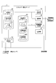
- FIG. 1 is a block diagram showing an example of the configuration of a management system according to a first embodiment.
- the block diagram showing the example of composition of the energy management server in a 1st embodiment.
- FIG. 6 is a view showing an example of a detection result table in the first embodiment.
- the figure which shows an example of the entrance / exit table in 1st Embodiment.
- the 1st figure showing the example of the zone in the building in a 1st embodiment.
- the 2nd figure showing the example of the zone in the building in a 1st embodiment.
- FIG. 5 is a view showing an example of a zone table in the first embodiment.
- FIG. 2 is a block diagram showing an example of the configuration of an information device management server according to the first embodiment.
- FIG. 2 is a block diagram showing an example of a hardware configuration of a monitoring terminal according to the first embodiment.
- the 1st sequence figure showing the operation in the whole management system of a 1st embodiment.
- FIG. 6 is a view showing another configuration example in the management system of the first embodiment.
- the block diagram which shows the structural example of the management system in 2nd Embodiment.
- the 1st figure showing the example of the zone in the building in a 2nd embodiment.
- the 2nd figure showing the example of the zone in the building in a 2nd embodiment.
- FIG. 7 is a block diagram showing an example of the configuration of an information device management server according to a second embodiment.
- the 2nd sequence figure showing the operation in the whole management system of a 2nd embodiment.
- FIG. 1 is a block diagram showing an example of the configuration of a management system in the first embodiment.
- the management system monitors energy consumed by facility equipment provided in the building and energy consumed by at least one information device used in the building.
- the equipment in each of the following embodiments includes not only equipment provided in the building but also equipment provided outside the building, such as an outdoor unit of air conditioning equipment. The same applies to information equipment.
- the buildings to be managed by the management system are, for example, office buildings. In the following description, the case where the building is an office building will be described, but the management system may be a building where information equipment is used, such as a library, a research facility, a university building or the like.
- An information device is a device capable of wired or wireless communication, such as a desktop type or laptop type personal computer (PC), a printer, a copier, a multifunction peripheral, an IP telephone, and a network device that enables communication between computers. is there.
- the management system includes an energy management server 1, an information device management server 5, and a monitoring terminal 10.
- the energy management server 1 may be provided in a building targeted for energy reduction by the management system, or may be provided in a different place from the building.
- the energy management server 1 is connected to the entrance / exit management system 2 via the network configured using either or both of the wired line and the wireless line. It communicates with the detection sensor 3 and the equipment 4 provided.
- the information device management server 5 may be provided in a building or may be provided in a different place from the building. Further, one or both of the energy management server 1 and the information device management server 5 may be configured using cloud computing.
- the buildings targeted for energy reduction by the management system may be a plurality of buildings, a plurality of office buildings, a plurality of buildings constructed in a certain area, or the like.
- the energy management server 1 acquires entry and exit information regarding entry and exit in a building from the entry and exit management system 2.
- the entry and exit management system 2 detects a person who enters and leaves the building to be managed and a person who leaves the building, and generates entry and exit information based on the detection result.
- the energy management server 1 acquires the detection signal which concerns on a person's detection from each of several detection sensor 3 with which the building was equipped.
- the detection signal is hereinafter referred to as presence / absence information.
- Each detection sensor 3 is provided in each of a plurality of zones related to a building. Each detection sensor 3 determines the presence or absence of a person in the zone, and generates presence / absence information based on the determination result.
- the presence / absence information includes a zone ID uniquely identifying the zone, and information indicating presence / absence (“present” / “absent”) of a person in the zone.
- the detection sensor 3 includes, for example, an image sensor and an infrared sensor, and detects the presence or absence of a person or the movement of a person based on an output from the sensor. If the detection accuracy of the detection sensor 3 is high and the number of people can be detected, the detection sensor 3 may notify presence / absence information indicating the number of people to the energy management server 1 instead of the presence or absence of a person.
- the absence information is also referred to as presence information.
- the zone is defined in a predetermined area of the building based on the positions of the plurality of PCs 6 and the plurality of shared devices 7 used in the building.
- the zones may be defined, for example, by dividing the area of a building, or may be defined such that there exist overlapping partial areas between adjacent zones. Also, zones may be defined according to the position of the information devices grouped according to the energy reduction policy. Specifically, if the area of the building is a floor of each floor in the building, one or more zones are defined for each floor.
- the energy management server 1 controls the facility devices 4 provided in each zone based on the entry / exit information acquired from the entry / exit management system 2 and the presence / absence information acquired from each detection sensor 3.
- the equipment 4 is a device provided in a building, and the power consumed directly or indirectly changes according to the operation state.
- the equipment 4 is, for example, a lighting device, an air conditioner, an intake / exhaust fan, a water supply pump, a water heater, a blind provided on a window, or the like.
- the blind is not a device that constantly consumes energy, but is a device that can change the solar radiation from the window by opening and closing the blind and can indirectly change the power consumed by the air conditioner and the like.
- the energy management server 1 tabulates the entry / exit information and the presence / absence information, and transmits data obtained by the tabulation to the information device management server 5 as a tabulation result.
- the energy management server 1 acquires first power consumption information related to the power consumed by the information device controlled by the information device management server 5.
- the energy management server 1 acquires second power consumption information related to the power consumed by the facility device.
- the energy management server 1 stores the first and second power consumption information in relation to the zone based on the entry / exit information and the presence / absence information.
- the monitoring terminal 10 is communicably connected to the energy management server 1.
- the monitoring terminal 10 acquires and displays information stored in the energy management server 1 based on the first and second power consumption information.
- the monitoring terminal 10 is used, for example, by a building manager.
- the manager operates the monitoring terminal 10 to display the power consumed by the building on the monitoring terminal 10, and confirms and monitors the power consumption.
- FIG. 1 illustrates the case where the management system includes one monitoring terminal 10, the management system may include a plurality of monitoring terminals 10.
- the monitoring terminal 10 may be provided in the same position as the energy management server 1, and may be provided in a different position.
- the energy management server 1 is configured using cloud computing, the monitoring terminal 10 acquires and displays information by accessing computer resources configuring the energy management server 1 via a network.
- the energy management server 1 and the information device management server 5 are communicably connected.
- the energy management server 1 and the information device management server 5 may be connected via a dedicated line or a local area network, or may be connected via the Internet.
- the energy management server 1 and the information device management server 5 may communicate using a VPN (Virtual Private Network). .
- the information device management server 5 acquires the presence or absence of people in each zone in the building and the entrance and exit of each person to the building from the counting result.
- the information device management server 5 controls the information devices belonging to each zone based on the information on the person in each zone to reduce the power consumed by the information devices in the building.
- the information device is the PC 6 or shared device 7 used by a person.
- the PC 6 is a desktop or laptop computer.
- the shared device 7 is a device shared by a plurality of persons such as a printer, a copier, a multifunction device, a hub for enabling communication between computers, a network device such as a switch or a wireless LAN access point, and an IP telephone.
- the information device management server 5 acquires information indicating the power or the amount of power consumed by the PC 6 and the shared device 7, and transmits the acquired information to the energy management server 1.
- Each zone in the building is equipped with at least one detection sensor 3 and one or more equipment devices 4. Also, at least one or both of the PC 6 and the shared device 7 belong to each zone in the building.
- the information device management server 5, the PC 6, and the shared device 7 may be connected via a dedicated line or a local area network, or may be connected via the Internet. When the information device management server 5 communicates with the PC 6 and the shared device 7 via the Internet, the information device management server 5 may communicate with the PC 6 and the shared device 7 using a VPN.
- FIG. 2 is a block diagram showing a configuration example of the energy management server 1 in the first embodiment.
- the energy management server 1 includes an in-building database 11, a power consumption database 12, a database update unit 13, a data processing unit 14, a communication unit 15, an equipment control unit 16, and a power supply unit 17.
- the in-building database 11 stores a detection result table 111 and an entrance / exit table 112 as information on people in the building.
- the detection result table 111 stores the presence or absence of a person in each zone.
- the entry / exit table 112 stores the entry / exit status of each person who uses the building, and the entry / exit status.
- the power consumption database 12 stores a zone table 121, an information device table 122, and an equipment device table 123.
- the information device table 122 stores, for each information device, information on the power consumption of the information device such as the PC 6 and the shared device 7.
- the equipment device table 123 stores information on the power consumption of the equipment 4 for each equipment 4.
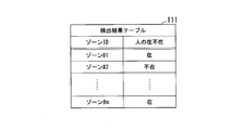
- FIG. 3 is a diagram showing an example of the detection result table 111 in the first embodiment.
- the detection result table 111 includes a row of an item of zone ID and an item of absence or presence of a person. A row exists for each zone.
- the zone ID field stores a zone ID (for example, zone # 1) that uniquely identifies the zone.
- zone # 1 a zone ID that uniquely identifies the zone.
- the “present” / “absent” of the person is stored in the zone indicated by the zone ID of the same row.
- "Present” indicates that at least one person has been detected.
- "Missing” indicates that no person was detected.
- the detection result table 111 of FIG. 3 stores that a person is absent in the zone indicated by zone # 2.
- the detection result table 111 may include a row of other items.
- the item of “person present / absent” may include the updated “time” column, or may include the column of the number of persons if the detection sensor 3 can detect the number of persons.
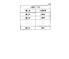
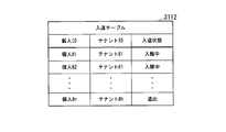
- FIG. 4 is a diagram showing an example of the entry / exit table 112 in the first embodiment.
- the entry and exit table 112 includes columns of items of personal ID and items of entry and exit status. There is a row for each person entering and leaving the building.
- a personal ID for example, personal # 1 uniquely identifying a person who enters or leaves the building is stored.
- the entry / exit state item it is stored whether the person indicated by the personal ID in the same row is "in” or "out” in the building.
- the entry / exit table 112 in FIG. 4 stores that the person identified by the personal ID # 2 is entering.
- the entry / exit table 112 has a row of two items “personal ID” and “entry / exit state”
- the entry / exit table may include rows of other items. For example, it may include a column of "time” in which the "entry / exit status" item is updated.
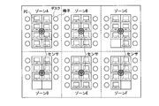
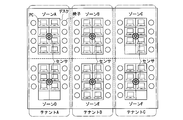
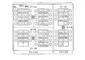
- FIG.5 and FIG.6 is a figure which shows the example of the zone in the building in 1st Embodiment. 5 and 6 show examples of zoning based on a desk and a chair used in an office and a PC provided on the desk.
- one zone is defined for each set of desks equipped with a PC, and the office is divided into six zones A to F.
- one zone is defined for each of two sets of desks equipped with a PC, and the office is divided into three zones AC.
- the zone is determined based on the position of the information device such as the PC 6.
- a sensor as a detection sensor 3 provided in each zone is attached to, for example, a ceiling, and detects the presence or absence of a person in the zone.
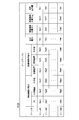
- FIG. 7 is a diagram showing an example of the zone table 121 in the first embodiment.
- the zone table 121 stores the power consumption and the amount of power consumption in the building for each zone.
- the power consumption and the power consumption of each zone are the power consumption and the power consumption of the equipment 4 and the power consumption and the power consumption of the information equipment such as the PC 6 and the shared equipment 7 controlled by the information equipment management server 5; Divided and stored.
- the zone table 121 includes zone ID, power of information equipment including PC and shared equipment, power of equipment including air conditioner and lighting equipment, total power, power of information equipment, and power of equipment. It includes a column of each item of power amount and total power amount. A row exists for each zone.
- the zone ID is stored in the zone ID item.
- the item of power of the information device includes items such as PC and shared device included in the information device, and stores the value of power consumed by the PC, shared device, and the like.
- the item of power of equipment includes items such as an air conditioner and a lighting device included in the equipment, and the value of power consumed by the air conditioner, the lighting device, and the like is stored.
- the total power item stores the total value of the power consumed by the information devices provided in the building and the facility devices.
- the value of the amount of power of the information device the value of the amount of power consumed by the information device in the period of the aggregation unit is stored.
- the value of the power consumed by the equipment during the period of the aggregation unit is stored.
- the information device is divided into “PC”, “shared device” and “others”, but other items may be included in the information device.
- the equipment is divided into “air conditioner”, “lighting device”, and “others”, other items may be included in the equipment.
- the value of the power consumed by the PC and the shared device in the zone table 121 is the value of the power consumed by each PC and the shared device instead of the value obtained by totaling the power consumption of the PCs and shared devices belonging to the zone. May be
- a plurality of power amounts may be stored for the information device, the facility device, and the total power amount, with the hour, 12 hours, 1 day, and 1 week as the aggregation unit, respectively.
- FIG. 8 is a diagram showing an example of the information device table 122 in the first embodiment.
- the information device table 122 includes columns of items of information device ID, power consumption, power consumption, operation state, power source used, and history information. A row exists for each information device.
- an information device ID (for example, PC # 1) that uniquely identifies an information device such as the PC 6 and the shared device 7 is stored.
- the zone ID field stores the zone ID indicating the zone to which the information device indicated by the information device ID in the same row belongs.
- the items of power consumption and power consumption store the power consumed by the information device indicated by the information device ID in the same row and the amount of power.
- the operating state includes, for example, "on”, “off", and “sleep".
- On is a state in which the information device is operating
- off is a state in which the information device is stopped.
- Sleep is a state in which the power consumption is smaller than in the "on” state, and the time required for the information device to be in the operating state is shorter than the "off” state.
- the item of used power stores information indicating the power used by the information device indicated by the information device ID in the same row.
- a power source for example, there are “Battery” and “AC”.
- Battery is a state using a primary or secondary battery provided in the information device as a power source
- AC is a state using an external power source of the information device, for example, a commercial power source.
- the history information item stores the history of changes in the operation state of the information device indicated by the information device ID in the same row.
- the history includes information indicating a time series of a combination of the time when the operation state has changed and the operation state after the change.
- the information device (PC 6) indicated by PC # 1 belongs to the zone indicated by zone # 1, and the power consumption, power consumption, operating state, power supply used of the information device. It stores that the history information is “pw01”, “ee01”, “sleep”, “Battery”, and “XXXX”, respectively.
- FIG. 9 is a diagram showing an example of the equipment device table 123 in the first embodiment.
- the equipment device table 123 includes columns of equipment device ID, zone ID, power consumption, power consumption, operation status, and history information. A row exists for each equipment 4.
- An equipment device ID uniquely identifying the equipment device 4 is stored in the item of the equipment device ID.
- a zone ID indicating a zone in which the facility device 4 indicated by the facility device ID in the same row is stored.
- the items of power consumption and power consumption store the power consumed by the equipment 4 indicated by the equipment device ID in the same row and the amount of power.
- the operation state item stores the operation state of the facility device 4 indicated by the facility device ID in the same row.
- the operating state includes, for example, "on” and "off”.
- the history information item stores the history of changes in the operation state of the facility device indicated by the facility device ID in the same row.
- This history is information similar to the history information in the information device table 122.
- the facility device 4 indicated by the facility device # 2 belongs to the zone indicated by the zone # 1, and the power consumption, power consumption, operation state, and history information of the facility device 4 It stores that "pw12", "ee12", "on”, and "BBBB", respectively.
- the database updating unit 13 updates the entry and exit table 112 based on the entry and exit information.
- the entry and exit information includes an individual ID uniquely identifying a person who has entered or left the building, and information indicating that the person has entered the building or that the person has left the building.
- the database updating unit 13 updates the state (during entering or leaving) in the entry / exit table 112 associated with the personal ID included in the entry / exit information based on the entry / exit information. Also, when acquiring the presence / absence information from the detection sensor 3 provided in each zone, the database updating unit 13 updates the detection result table 111 on the basis of the presence / absence information.
- the presence / absence information includes a zone ID that uniquely identifies the zone, and information indicating the presence or absence of a person in the zone.
- the database updating unit 13 updates the presence (“present” or “absent”) of the person associated with the zone ID included in the presence / absence information based on the presence / absence information.
- the data processing unit 14 generates data based on the presence / absence information acquired by the database updating unit 13 and the zone IDs of a plurality of zones related to the building. Specifically, the data processing unit 14 collects the information stored in the detection result table 111 and the entry / exit table 112, and detects the zone ID of the zone in which the information has been changed or the personal ID of a person. The data processing unit 14 may collect information in a fixed cycle, or may collect information in response to a request from the information device management server 5. The data processing unit 14 outputs the counting result to the communication unit 15 as data including the zone ID of the changed zone or the personal ID of a person, and requests the communication unit 15 to transmit the counting result.
- the data processing unit 14 may further include a zone ID indicating a zone in which a person is present in the counting result. Further, the data processing unit 14 tabulates the detection result table 111 and the entry / exit table 112 in the in-building database 11 at a constant cycle, and generates a tabulated result as data.
- the counting result in this case includes information indicating a zone in which a person is present and a zone in which no person is present, and the personal ID of the person who is entering the building.
- the communication unit 15 transmits the counting result output from the data processing unit 14 to the information device management server 5.
- the data processing unit 14 receives the state information as first power consumption information from the information device management server 5 via the communication unit 15.
- the state information is information on power consumed by information devices such as the PC 6 and the shared device 7.
- the state information includes an information device ID, a zone ID of a zone to which the information device indicated by the information device ID belongs, power consumption of the information device, power consumption, information indicating an operation state, information indicating a power source used, Information indicating whether or not the operation indicated by the operation state is started. Whether or not the information device is used is determined based on the operating state of the information device and whether an input device (a keyboard, a mouse, etc.) provided in the information device receives a human operation.
- an input device a keyboard, a mouse, etc.
- the data processing unit 14 updates the information device table 122 based on the first power consumption information. Specifically, the data processing unit 14 detects, in the information device table 122, a row including the information device ID that matches the information device ID included in the acquired first power consumption information. The data processing unit 14 updates the information of each item included in the detected row based on the acquired first power consumption information. Regarding history information, the data processing unit 14 determines whether or not a change has occurred in the operation state based on the information indicating the operation state included in the state information. When a change in the operation state is detected, the data processing unit 14 updates the history information by adding information indicating the operation state after the change and the time when the operation state was started to the history information.
- the data processing unit 14 updates each information related to the information device in the zone table 121 and the total power and the total amount of power based on the information stored in the information device table 122 or the first power consumption information. For example, the data processing unit 14 reads the power consumption of the row including the information device ID indicating the PC 6 from the information device table 122 for each zone ID. The data processing unit 14 calculates the total value of the read power consumption for each zone ID, and updates the power of the PC in the zone table 121 for each zone with the total value. The data processing unit 14 updates the power of the shared device, the other power, the total power, the power of the information device, and the total power in the zone table 121 by the same operation.
- the data processing unit 14 may request the status information from the information device management server 5 via the communication unit 15 to obtain status information, or obtain status information periodically transmitted from the information device management server 5 You may The data processing unit 14 may update the information device table 122 and the zone table 121 each time the state information as the first power consumption information is acquired, or the information device table 122 and the zone table 121 may be updated in a fixed cycle. It may be updated.
- the communication unit 15 communicates with the information terminal management server 5 as described above, and communicates with the monitoring terminal 10. In response to a request for information received from the monitoring terminal 10, the communication unit 15 reads out and returns information stored in the power consumption database 12.
- the equipment control unit 16 controls the equipment 4 in each zone in the building based on the detection result table 111. For example, when there is no person in zone A, the facility device control unit 16 reduces the power consumption by stopping the facility device 4 provided in the zone A or lowering the operation level. Lowering the operation level of the equipment 4 means, for example, raising the temperature of the air supplied from the air conditioning equipment when the equipment 4 is an air conditioner and is performing a cooling operation.
- the equipment 4 is a lighting device
- the lighting device may be turned off, the light emitted by the lighting device may be weakened, or the lighting device may be turned off after a predetermined time has passed since no person was detected. Do.
- the equipment 4 is an intake / exhaust fan that circulates air in the building or a feed water pump that supplies cold water or hot water into the building, the flow rate per unit time may be reduced or continuous operation may be intermittent. Switch to driving.
- the cooling efficiency is improved by blocking the solar radiation from the window to the room to lower the operation level of the air conditioner, or the solar radiation from the window is taken into the room to improve the heating efficiency. Improve and lower the operation level of the air conditioner.
- the equipment control unit 16 may control the opening and closing of the blinds so as to suppress a change in room temperature.
- the facility device control unit 16 acquires second power consumption information from each of the facility devices 4.
- the second power consumption information is information related to the power consumed by the facility device 4.
- the second power consumption information includes an equipment device ID, a zone ID of a zone in which the equipment device 4 indicated by the equipment device ID is located, power consumption of the equipment device 4, power consumption, information indicating an operation state, and an operation state Including the time when the operation shown in FIG.
- the facility device control unit 16 updates the facility device table 123 based on the second power consumption information. Specifically, the facility device control unit 16 detects, in the facility device table 123, a row including the facility device ID that matches the facility device ID included in the acquired second power consumption information. The facility device control unit 16 updates the information of each item included in the detected row based on the acquired second power consumption information.
- the facility device control unit 16 updates each information related to the facility device in the zone table 121, the total power and the total power amount, based on the information stored in the facility device table 123 or the second power consumption information. For example, the facility device control unit 16 reads out the power consumption of the row including the facility device ID indicating the air conditioner from the facility device table 123 for each zone ID. The facility equipment control unit 16 calculates the total value of the read power consumption for each zone ID, and updates the power of the air conditioner in the zone table 121 for each zone with the total value. The facility device control unit 16 updates the power of the lighting device in the zone table 121, the other power, the total power, the power amount of the facility device, and the total power amount by the same operation.
- the facility device control unit 16 may acquire the second power consumption information from the facility device 4 at a predetermined cycle, or acquire the second power consumption information from the facility device 4 at each predetermined time. You may The facility device control unit 16 may update the facility device table 123 and the zone table 121 every time the second power consumption information is acquired, or update the facility device table 123 and the zone table 121 at a constant cycle. It is also good.
- the power supply unit 17 includes an in-building database 11, a power consumption database 12, a database updating unit 13, a data processing unit 14, a communication unit 15, and equipments provided in the energy management server 1 with power received from an external generator or commercial power supply. It supplies to each control part 16.
- the power supply unit 17 may include a secondary battery or the like so that supply of power can be continued even when power can not be received from an external generator and a commercial power supply.
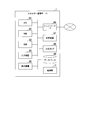
- FIG. 10 is a block diagram showing a configuration example of the information device management server 5 in the first embodiment.
- the information device management server 5 includes an information device database 51, a communication unit 52, an information device control unit 53, a network interface (network I / F) 54, and a power supply unit 55.
- An information device table 511 and a use device table 512 are stored in the information device database 51 as information device information related to the information device.
- the information device table 511 stores zones to which the PC 6 and the shared device 7 belong. Specifically, a combination of an information device ID uniquely identifying each of the PC 6 and the shared device 7 and a zone ID indicating a zone to which the PC 6 or the shared device 7 belongs is stored.
- the PC 6 belongs to any zone.
- the laptop PC 6 belongs to a zone in which the PC 6 is mainly used. That is, all the PCs 6 and all the shared devices 7 belong to any zone.
- the use device table 512 stores information indicating the PC 6 used by a person. Specifically, in the use device table 512, a combination of a person's personal ID and an information device ID for uniquely identifying the PC 6 is stored.
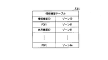
- FIG. 11 is a diagram showing an example of the information device table 511.
- the information device table 511 includes columns of items of information device ID and items of zone ID. A row exists for each information device.
- an information device ID for example, PC # 1 for identifying the information device is stored.
- the zone ID field stores the zone ID indicating the zone to which the information device identified by the information device ID in the same row belongs. That is, in the information device table 511, a combination of the information device ID of the information device and the zone ID of the zone to which the information device belongs is stored.
- the information device table 511 in FIG. 11 stores that the information device identified by shared device # 2 is mainly used in the zone indicated by zone # 1.
- FIG. 11 shows an example in which the information device ID and the zone ID are associated one-to-one, but a plurality of zone IDs may be associated with the information device ID.
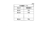
- FIG. 12 is a diagram showing an example of the use device table 512.
- the use device table 512 includes columns of an item of personal ID and an item of information device ID. A row exists for each person entering and leaving the building.
- a personal ID for example, personal # 1 is stored.
- an information device ID indicating an information device used by a person identified by the personal ID in the same row is stored.
- the use device table 512 in FIG. 12 stores that a person identified by the individual # 1 uses the information device identified by the PC # 1.
- FIG. 12 shows an example in which the personal ID and the information device ID are associated one to one, but when a person uses a plurality of information devices, the plurality of information device IDs are associated with the personal ID. It is also good.
- the communication unit 52 communicates with the energy management server 1.
- the communication unit 52 receives the counting result as data transmitted from the energy management server 1, and outputs the counting result to the information device control unit 53.
- the information device control unit 53 uses the information device table 511 and the use device table 512 stored in the information device database 51, and the PC 6 or the shared device 7 to be subjected to power consumption reduction based on the counting result as data. Choose The information device control unit 53 controls the selected PC 6 or the shared device 7 to suppress the power consumed by the PC 6 or the shared device 7. For example, the information device control unit 53 transmits control information including an instruction to change the operation state to “off” or “sleep” to the PC 6 and the shared device 7 belonging to a zone where there is no person.
- the information device control unit 53 acquires state information from each of the information devices of the PC 6 and the shared device 7 via the network I / F 54.
- the information device control unit 53 transmits the acquired state information to the energy management server 1 via the communication unit 52.
- the information device control unit 53 requests transmission of the state information to each of the information devices of the PC 6 and the shared device 7 at a predetermined cycle or timing, and acquires the state information returned as a response.
- the information device control unit 53 may obtain, via the network I / F 54, status information transmitted from the information devices of the PC 6 and the shared device 7 in a constant cycle.
- the information device control unit 53 regards the operation state of the information device of the PC 6 or the shared device 7 for which the response was not obtained as “off”, generates state information of the information device, and transmits it to the energy management server 1 Do.
- the network I / F 54 communicates with the PC 6 and the shared device 7 located in the building.
- the network I / F 54 transmits the control information generated by the information device control unit 53 to the PC 6 or the shared device 7.
- the network I / F 54 receives the status information from the PC 6 or the shared device 7 as the control target, and requests the communication unit 52 to transmit the received status information to the energy management server 1.
- the power supply unit 55 supplies power received from an external generator or commercial power supply to the information device database 51, the communication unit 52, the information device control unit 53, and the network I / F 54 provided in the information device management server 5. Similar to the power supply unit 17 provided in the energy management server 1, the power supply unit 55 can be a secondary battery or the like so that supply of power can be continued even when power can not be received from an external generator and a commercial power supply. May be provided.
- FIG. 13 is a block diagram showing an example of the hardware configuration of the energy management server 1.
- the energy management server 1 includes a CPU 81, a RAM 82, a ROM 83, an input device 84, a display device 85, a network I / F 86, a storage device 87, an input / output I / F 88, a database 89, and a power supply unit 17.
- the CPU 81 reads a program non-temporarily stored in the storage device 87 or the ROM 83 configured by an HDD, a solid state drive (SSD), or the like into the RAM 82, and executes the read program.
- SSD solid state drive
- the CPU 81 operates as the database updating unit 13, the data processing unit 14, and the equipment control unit 16 by executing processing according to the operation of the user or the administrator input by the input device 84 such as a mouse or a keyboard.
- the network I / F 86 operates as the communication unit 15.
- the database 89 operates as the in-building database 11 and the power consumption database 12.
- the CPU 81 acquires entry / exit information from the entry / exit management system 2 via the input / output I / F 88 and acquires presence / absence information from each of the detection sensors 3.
- the CPU 81 operating as the database updating unit 13 updates the information stored in the database 89 operating as the in-building database 11 based on the acquired entry / exit information and the presence / absence information.
- the CPU 81 operating as the data processing unit 14 tabulates the information stored in the in-building database 11 and the database 89 operating as the power consumption database 12.
- the network I / F 86 operating as the communication unit 15 transmits the counting result obtained by the counting to the information device management server 5.
- the CPU 81 operating as the data processing unit 14 and the equipment control unit 16 acquires first and second power consumption information.
- the CPU 81 updates the information stored in the database 89 operating as the power consumption database 12 based on the first and second power consumption information.
- the display device 85 displays the information of the power consumption database 12 included in the database 89.
- the display device 85 displays, for example, the zone table 121, the information device table 122, and the facility device table 123 shown in FIGS. 7, 8 and 9.
- the energy management server 1 enables monitoring of the power consumed by all the devices related to the building by displaying the power consumed by the equipment devices and the information devices for each zone.
- the energy management server 1 may be implemented using hardware including the CPU 81 that executes a program.
- the information device management server 5 may also be implemented using hardware including a CPU that executes a program.
- the CPU 81 operates as the information device control unit 53 by executing a process according to the operation of the user or the administrator input by the input device 84 such as a mouse or a keyboard.
- FIG. 14 is a block diagram showing an example of the hardware configuration of the monitoring terminal 10.
- the monitoring terminal 10 includes a CPU 101, a RAM 102, a ROM 103, an input device 104, a display device 105, a network I / F 106, a storage device 107, and a power supply unit 117.
- the CPU 101 reads a program non-temporarily stored in the storage device 107 or the ROM 103 configured of an HDD, an SSD, or the like into the RAM 102, and executes the read program.
- the CPU 101 executes, based on a program, processing in accordance with the operation of the administrator input by the input device 104 such as a mouse or a keyboard. Specifically, the CPU 101 requests the energy management server 1 for the information stored in the in-building database 11 or the power consumption database 12, and causes the display device 105 to display the information obtained as a response.
- the display device 105 displays a screen based on a program executed by the CPU 101. For example, the display device 105 displays the information stored in the in-building database 11 or the power consumption database 12. The display device 105 displays, for example, the zone table 121, the information device table 122, and the facility device table 123 shown in FIGS. 7, 8 and 9. The display device 105 may display the detection result table 111 and the entry / exit table 112 stored in the in-building database 11.
- the network I / F 106 communicates with the energy management server 1 according to an instruction of the CPU 101. The network I / F 106 transmits a request for information to the energy management server 1 or receives a response from the energy management server 1 based on an instruction from the CPU 101.
- the power supply unit 117 supplies power received from an external generator or a commercial power supply to the CPU 101, the RAM 102, the ROM 103, the input device 104, the display device 105, the network I / F 106, and the storage device 107 provided in the monitoring terminal 10.
- the power supply unit 117 may include a secondary battery or the like so that supply of power can be continued even when power can not be received from the outside.
- the monitoring terminal 10 updates the information stored in the power consumption database 12 in addition to requesting the energy management server 1 for the information stored in the in-building database 11 or the power consumption database 12. May be required.
- the data processing unit 14 acquires first power consumption information of each information device from the information device management server 5, and the zone table 121 and the information device
- the information stored in the table 122 is updated.
- the facility device control unit 16 acquires second power consumption information from each of the facility devices 4, and updates the information stored in the zone table 121 and the information device table 122.
- the PC 6 used in the building may perform the same operation as the operation performed by the monitoring terminal 10. For example, even if a person who uses the PC 6 in the building operates the PC 6 to request the information stored in the power consumption database 12 from the energy management server 1 in order to confirm the power consumed in the building Good.
- the monitoring terminal 10 and the PC 6 when displaying information related to the power consumed by the building, the monitoring terminal 10 displays a graph or a table generated based on the information in the zone table 121, the information device table 122, and the facility device table 123. And the PC 6 may be displayed.
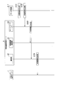
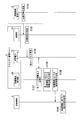
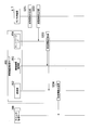
- FIG. 15 and 16 transmit the state information acquired by the information device management server 5 to the energy management server 1, and the energy management server 1 updates the power consumption database 12 based on the state information as the first power consumption information.
- FIG. 15 shows the process which performs and control of the installation apparatus 4.
- the PC 6 or the shared device 7 generates state information which is information related to the power consumed by itself (step S101).
- the generation of the state information by the PC 6 and the shared device 7 may be performed in response to a request from the information device management server 5, or may be performed at a predetermined cycle or timing. Also, the PC 6 and the shared device 7 may generate state information in response to a human operation.
- the PC 6 or the shared device 7 transmits the status information to the information device management server 5 (step S102).
- the network I / F 54 transfers the state information received from the PC 6 or the shared device 7 to the information device control unit 53 and the communication unit 52 (step S103).
- the communication unit 52 transmits the state information to the energy management server 1 via the network I / F 54 (step S104).
- the communication unit 52 may temporarily store the state information obtained from the plurality of PCs 6 and the shared device 7 and collectively transmit the plurality of state information to the energy management server 1 each time the state information is obtained. It may be sent to the energy management server 1.
- the information device control unit 53 receives via the network I / F 54. A process of adding a zone ID to state information is performed.
- the information device control unit 53 acquires, from the information device table 511, a zone ID corresponding to the information device ID included in the state information, and adds the acquired zone ID to the state information.
- the information device control unit 53 transmits state information including the zone ID to the energy management server 1 via the communication unit 52.
- the transfer of the state information from the network I / F 54 to the communication unit 52 may not be performed.
- the communication unit 15 transfers the state information received from the information device management server 5 to the data processing unit 14 (step S105).
- the data processing unit 14 updates the information device table 122 and the zone table 121 stored in the power consumption database 12 based on the state information (step S106).
- the facility device control unit 16 counts the power consumption of the facility device 4 stored in the zone table 121 (step S107). For the aggregation by the facility device control unit 16, for example, a zone in which the information device is not used is detected based on the power consumption, or the ratio of the power consumption of the facility device 4 to the power consumption in the zone is calculated for each zone And calculating the ratio of the power consumption of the facility device 4 related to the building and the information device.
- the equipment control part 16 determines the necessity of the control with respect to the equipment 4 for every zone based on a total result (step S108). For example, the presence or absence of the facility device 4 operating in a zone where the information device is not used is determined. When there is the facility device 4 operating in such a zone, the facility device control unit 16 transmits control information including an instruction to stop or lower the operation level to the facility device 4 operating in the zone (Step S109). The equipment 4 having received the control information changes the operating state (step S110).
- the energy management server 1 stops the facility equipment 4 in the zone or lowers the operation level based on the operation states of the PC 6 and the shared equipment 7 controlled by the information equipment management server 5, without impairing the convenience of people. Power consumption can be reduced.
- the energy management server 1 acquires and stores the power consumed by the information device and the facility device 4 in the building. Since the energy management server 1 tabulates the power consumption of each of the information equipment and the equipment 4 for each of a plurality of zones related to the building, it is possible to monitor the power consumption in the building. In addition, the energy management server 1 performs control to suppress the power consumed by the facility device 4 based on the power consumption for each zone, whereby power consumption can be reduced.
- the facility device control unit 16 may detect a zone in which the power consumed by the information device is equal to or greater than a predetermined value, and may perform control to suppress the power consumed by the facility device 4 in the detected zone. By this control, the management system can reduce the total power consumption in the zone and can reduce the power consumption in the entire building.
- the data processing unit 14 may detect a zone in which a person is present based on the detection result table 111, and request the information device management server 5 for status information on an information device in the detected zone.
- the data processing unit 14 increases the frequency of updating power consumption of a zone estimated to have high power consumption of the information device by acquiring state information of the information device in a zone where there is a person and updating the power consumption database 12. Thus, it is possible to improve real-time performance in monitoring of power consumption.
- the history information of the information device in the information device table 122 has been described as the configuration in which the data processing unit 14 is updated based on the state information.
- each of the PC 6 and the shared device 7 may generate own history information, and transmit state information including the history information to the information device management server 5 and the energy management server 1.
- the information device stores the changed operation state and the current time in combination each time the operation state is changed.
- a time series of a combination of the changed operation state and the current time is history information of each information device.
- the database updating unit 13 causes the detection result table 111 to store the presence / absence information obtained from each detection sensor 3, and the information stored in the detection result table 111.
- the configuration has been described in which data obtained by aggregating the data processing unit 14 is transmitted to the information device management server 5.
- the energy management server 1 may transmit the presence / absence information obtained from each detection sensor 3 to the information device management server 5.
- the information device management server 5 receives presence / absence information, a combination of a sensor ID uniquely identifying the detection sensor 3 and an information device ID of an information device in which the detection sensor 3 is located in a detection range of a person is stored.
- the sensor table may be stored in the information device database 51.
- the information device management server 5 can control the information device based on the presence / absence information by providing the sensor table.
- the management system in the first embodiment may include one management server 200 instead of the two servers of the energy management server 1 and the information device management server 5.
- FIG. 17 is a diagram showing another configuration example of the management system in the first embodiment.
- the management server 200 includes an in-building database 11, a power consumption database 12, a database updating unit 13, a data processing unit 14, a communication unit 15, an equipment control unit 16, a power supply unit 17, and an information equipment database 51. , An information device control unit 53, and a network I / F 54.
- the communication unit 52 for performing communication between the energy management server 1 and the information device management server 5 is omitted.
- the power supply unit 55 is omitted.
- one server may perform the processing performed by the energy management server 1 and the information device management server 5.
- FIG. 18 is a block diagram showing an example of configuration of a management system in the second embodiment.
- the management system monitors energy consumed by facility equipment provided in the building and energy consumed by at least one information device used in the building.
- the building is an office building and there are multiple tenants in the office building.
- the management system in the second embodiment includes an energy management server 300, an entrance and exit management system 2, a plurality of detection sensors 3, a plurality of facility devices 4, and an information device management server 600.
- the energy management server 300 may be provided in a building targeted for energy reduction by the management system, or may be provided in a different place from the building.
- the energy management server 300 can use the entrance / exit management system 2 and the building via a network configured using either or both of a wired line and a wireless line. It communicates with the detection sensor 3 and the equipment 4 provided.
- the information device management server 600 may be provided in a building, or may be provided in a different place from the building.
- one or both of the energy management server 300 and the information device management server 600 may be configured using cloud computing.
- the buildings targeted for energy reduction by the management system may be a plurality of buildings, a plurality of office buildings, a plurality of buildings constructed in a certain area, or the like.
- the energy management server 300 acquires entry and exit information regarding entry and exit in the building from the entry and exit management system 2.
- the entry and exit management system 2 detects a person who enters and leaves the building to be managed and a person who leaves the building, and generates entry and exit information based on the detection result.
- the energy management server 300 acquires the detection signal which concerns on a person's detection from each of several detection sensor 3 with which the building was equipped.
- the detection signal is hereinafter referred to as presence / absence information.
- Each detection sensor 3 is provided in each of a plurality of zones related to a building. Each detection sensor 3 determines the presence or absence of a person in the zone, and generates presence / absence information based on the determination result.
- the presence / absence information includes a zone ID uniquely identifying the zone, and information indicating presence / absence (“present” / “absent”) of a person in the zone.
- the detection sensor 3 includes, for example, an image sensor and an infrared sensor, and detects the presence or absence of a person or the movement of a person based on an output from the sensor. If the detection accuracy of the detection sensor 3 is high and the number of people can be detected, the detection sensor 3 may notify presence / absence information indicating the number of people to the energy management server 300 instead of the presence or absence of people.
- the absence information is also referred to as presence information.
- the zone in the second embodiment is determined based on the section for lending to the tenant.
- the floor of each floor in the building may be divided into a plurality of sections, and each section may be defined in a zone.
- zones may be defined based on energy reduction policies.
- the energy management server 300 controls the equipment 4 provided in each zone based on the entry / exit information acquired from the entry / exit management system 2 and the presence / absence information acquired from each detection sensor 3.
- the equipment 4 is a device provided in a building, and the power consumed directly or indirectly changes according to the operation state.
- the equipment 4 is, for example, a lighting device, an air conditioner, an intake / exhaust fan, a water supply pump, a water heater, a blind provided on a window, or the like.
- the blind is not a device that constantly consumes energy, but is a device that can change the solar radiation from the window by opening and closing the blind and can indirectly change the power consumed by the air conditioner and the like.
- the energy management server 300 aggregates entry / exit information and presence / absence information, and transmits data obtained by the aggregation to the information device management server 600 as an aggregation result.
- the energy management server 300 acquires first power consumption information related to the power consumed by the information device controlled by the information device management server 600.
- the energy management server 300 acquires second power consumption information related to the power consumed by the facility device.
- the energy management server 300 stores the first and second power consumption information in relation to the zone based on the entry / exit information and the presence / absence information.
- the monitoring terminal 10 is communicably connected to the energy management server 300.
- the monitoring terminal 10 acquires and displays information stored in the energy management server 300 based on the first and second power consumption information.
- the monitoring terminal 10 is used, for example, by a building manager.
- the manager operates the monitoring terminal 10 to display the power consumed by the building on the monitoring terminal 10, and confirms and monitors the power consumption.
- FIG. 18 exemplifies the case where the management system includes one monitoring terminal 10, the management system may include a plurality of monitoring terminals 10.
- the monitoring terminal 10 may be provided at the same position as the energy management server 300 or may be provided at a different position.
- the energy management server 300 is configured using cloud computing, the monitoring terminal 10 acquires and displays information by accessing computer resources configuring the energy management server 300 via the network.
- the energy management server 300 and the information device management server 600 are communicably connected.
- the energy management server 300 and the information device management server 600 may be connected via a dedicated line or a local area network, or may be connected via the Internet.
- the energy management server 300 and the information device management server 600 may communicate using a VPN (Virtual Private Network). .
- the information device management server 600 acquires the presence or absence of a person in each zone in the building and the entrance and exit of each person to the building from the counting result.
- the information device management server 600 controls the information devices belonging to each zone based on the information on the person in each zone to reduce the power consumed by the information devices in the building.
- the information device is the PC 6 or shared device 7 used by a person.
- the PC 6 is a desktop or laptop computer.
- the shared device 7 is a device shared by a plurality of persons such as a printer, a copier, a multifunction device, a hub for enabling communication between computers, a network device such as a switch or a wireless LAN access point, and an IP telephone.
- the information device management server 600 acquires information indicating the power or the amount of power consumed by the PC 6 and the shared device 7, and transmits the acquired information to the energy management server 300.
- Each zone in the building is equipped with at least one detection sensor 3 and one or more equipment devices 4.
- at least one or both of the PC 6 and the shared device 7 belong to each zone in the building.
- the information device management server 600, the PC 6 and the shared device 7 may be connected via a dedicated line or a local area network, or may be connected via the Internet.
- the information device management server 600 may communicate with the PC 6 and the shared device 7 using a VPN.
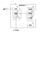
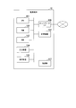
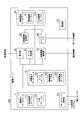
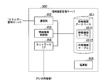
- FIG. 19 is a block diagram showing a configuration example of the energy management server 300 in the second embodiment.
- the energy management server 300 includes an in-building database 311, a power consumption database 312, a database updating unit 313, a data processing unit 314, a communication unit 315, an equipment control unit 316, and a power supply unit 317.
- a detection result table 3111, an entrance / exit table 3112 and a tenant table 3113 are stored as information on people in the building.
- the detection result table 3111 stores the presence or absence of a person in each zone.
- the entry / exit table 3112 stores the entry / exit status of each person who uses the building, and the entry / exit status.
- information indicating the zones leased by each tenant is stored.
- a zone to be leased to a tenant is also referred to as a zone belonging to the tenant or a zone used for the tenant.
- a zone table 3121, an information device table 3122 and an equipment device table 3123 are stored.
- the zone table 3121 stores, for each zone, information on power consumption of the facility device 4 and information devices such as the PC 6 and the common device 7.
- the information device table 3122 stores, for each information device, information related to the power consumption of the information device such as the PC 6 and the common device 7.
- Information on the power consumption of the facility device 4 is stored in the facility device table 3123 for each of the facility devices 4.
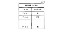
- FIG. 20 is a diagram showing an example of the detection result table 3111 in the second embodiment.
- the detection result table 3111 includes a row of an item of zone ID and an item of absence or presence of a person. A row exists for each zone.
- the zone ID field stores a zone ID (for example, zone # 1) that uniquely identifies the zone.
- zone # 1 a zone ID that uniquely identifies the zone.
- the “present” / “absent” of the person is stored in the zone indicated by the zone ID of the same row.
- "Present” indicates that at least one person has been detected.
- "Missing” indicates that no person was detected.
- the detection result table 3111 in FIG. 20 stores that a person is absent in the zone indicated by zone # 2.
- the detection result table 3111 may include columns of other items.
- the item of “person present / absent” may include the updated “time” column, or may include the column of the number of persons if the detection sensor 3 can detect the number of persons.
- FIG. 21 is a diagram showing an example of the entry / exit table 3112 in the second embodiment.
- the entry / exit table 3112 includes columns of an item of personal ID, an item of tenant ID, and an item of entry / exit status. There is a row for each person entering and leaving the building.
- a personal ID for example, personal # 1 uniquely identifying a person who enters or leaves the building is stored.
- the tenant ID field stores a tenant ID that uniquely identifies a tenant to which a person indicated by the personal ID in the same row belongs.
- the entry / exit state item it is stored whether the person indicated by the personal ID in the same row is "in” or "out” in the building.
- FIG. 21 stores that a person who is identified by the individual ID # 2 and belongs to the tenant indicated by the tenant ID # 1 is entering.
- FIG. 21 shows an example in which the entry / exit table 3112 has a row of three items of “personal ID”, “tenant ID” and “entry / exit status”, the entry / exit table is a row of other items. May be included. For example, it may include a column of "time” in which the "entry / exit status" item is updated.
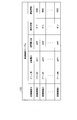
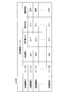
- FIG. 22 is a diagram showing an example of the tenant table 3113 in the second embodiment.
- the tenant table 3113 includes columns of zone ID items and tenant ID items. A row exists for each zone in the building.
- the zone ID field stores a zone ID (for example, zone # 2) that uniquely identifies the zone.
- the tenant ID field stores a tenant ID (for example, tenant # 1) that uniquely identifies a tenant using a zone indicated by the zone ID in the same row.
- tenant table 3113 in FIG. 22 stores that the zone indicated by zone # 2 belongs to the tenant indicated by tenant # 1.
- Each tenant uses at least one zone.
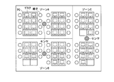
- FIG. 23 and 24 show examples of zones in a building.
- FIG. 23 illustrates an example in which one floor in a building is divided into six zones, and three tenants each use two zones.
- FIG. 23 shows the case where the tenant A uses zones A and D, the tenant B uses zones B and E, and the tenant C uses zones C and F.
- Each zone is provided with a detection sensor 3 for detecting a person.
- the detection sensor 3 is attached to, for example, the ceiling of each zone and detects the presence or absence of a person in the zone.
- FIG. 24 shows an example in which one floor in a building is divided into three zones, and two tenants use zones.
- FIG. 24 shows the case where the tenant A uses zones A and B and the tenant B uses zone C.
- Each zone is provided with a detection sensor 3 for detecting a person.
- the detection sensor 3 is attached to, for example, the ceiling of each zone and detects the presence or absence of a person in the zone.
- the detection range of the detection sensor 3 in the example shown in FIG. 24 is wider than the detection range of the detection sensor 3 in the example shown in FIG.
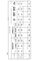
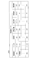
- FIG. 25 is a diagram showing an example of the zone table 3121 in the second embodiment.
- the zone table 3121 stores power consumption and power consumption in the building for each zone.
- the power consumption and the power consumption of each zone are the power consumption and the power consumption of the equipment 4 and the power consumption and the power consumption of the information equipment such as the PC 6 and the shared equipment 7 controlled by the information equipment management server 600; Divided and stored.
- the zone table 3121 includes zone ID, power of information equipment including PC and shared equipment, power of equipment including air conditioner and lighting equipment, total power, power of information equipment, and power of equipment. It includes a column of each item of power amount and total power amount. A row exists for each zone.
- the zone ID is stored in the zone ID item.
- the item of power of the information device includes items such as PC and shared device included in the information device, and stores the value of power consumed by the PC, shared device, and the like.
- the item of power of equipment includes items such as an air conditioner and a lighting device included in the equipment, and the value of power consumed by the air conditioner, the lighting device, and the like is stored.
- the total power item stores the total value of the power consumed by the information devices provided in the building and the facility devices.
- the value of the amount of power of the information device the value of the amount of power consumed by the information device in the period of the aggregation unit is stored.
- the value of the power consumed by the equipment during the period of the aggregation unit is stored.
- the information device is divided into “PC”, “shared device” and “others”, but other items may be included in the information device.
- the equipment is divided into “air conditioner”, “lighting device”, and “others”, other items may be included in the equipment.
- the value of the power consumed by the PC and the shared device in the zone table 3121 is the value of the power consumed by the individual PC and the shared device instead of the sum of the power consumption of the PCs and the shared devices belonging to the zone. May be
- a plurality of power amounts may be stored for the information device, the facility device, and the total power amount, with the hour, 12 hours, 1 day, and 1 week as the aggregation unit, respectively.
- FIG. 26 is a diagram showing an example of the information device table 3122 in the second embodiment.
- the information device table 3122 includes columns of items of information device ID, power consumption, power consumption, operation state, power source used, and history information. A row exists for each information device.
- an information device ID (for example, PC # 1) that uniquely identifies an information device such as the PC 6 and the shared device 7 is stored.
- the zone ID field stores the zone ID indicating the zone to which the information device indicated by the information device ID in the same row belongs.
- the items of power consumption and power consumption store the power consumed by the information device indicated by the information device ID in the same row and the amount of power.
- the operating state includes, for example, "on”, “off", and “sleep".
- On is a state in which the information device is operating
- off is a state in which the information device is stopped.
- Sleep is a state in which the power consumption is smaller than in the "on” state, and the time required for the information device to be in the operating state is shorter than the "off” state.
- the item of used power stores information indicating the power used by the information device indicated by the information device ID in the same row.
- a power source for example, there are “Battery” and “AC”.
- Battery is a state using a primary or secondary battery provided in the information device as a power source
- AC is a state using an external power source of the information device, for example, a commercial power source.
- the history information item stores the history of changes in the operation state of the information device indicated by the information device ID in the same row.
- the history includes information indicating a time series of a combination of the time when the operation state has changed and the operation state after the change.
- the information device (PC 6) indicated by PC # 1 belongs to the zone indicated by zone # 1, and the power consumption, power consumption, operating state, power supply used of the information device. It stores that the history information is “pw01”, “ee01”, “sleep”, “Battery”, and “XXXX”, respectively.
- FIG. 27 is a diagram showing an example of the equipment table 3123 in the second embodiment.
- the equipment device table 3123 includes columns of equipment device ID, zone ID, power consumption, power consumption, operation status, and history information. A row exists for each equipment 4.
- An equipment device ID uniquely identifying the equipment device 4 is stored in the item of the equipment device ID.
- a zone ID indicating a zone in which the facility device 4 indicated by the facility device ID in the same row is stored.
- the items of power consumption and power consumption store the power consumed by the equipment 4 indicated by the equipment device ID in the same row and the amount of power.
- the operation state item stores the operation state of the facility device 4 indicated by the facility device ID in the same row.
- the operating state includes, for example, "on” and "off".
- the history information item stores the history of changes in the operation state of the facility device indicated by the facility device ID in the same row.
- This history is the same information as the history information in the information device table 3122.
- the facility device table 3123 in FIG. 27 belongs to the zone in which the facility device 4 represented by the facility device # 2 is represented by the zone # 1, and the power consumption, power consumption, operating state, and history information of the facility device 4 It stores that "pw12", "ee12", "on”, and "BBBB”, respectively.
- the database updating unit 313 updates the entry and exit table 3112 based on the entry and exit information.
- the entry and exit information includes an individual ID uniquely identifying a person who has entered or left the building, and information indicating that the person has entered the building or that the person has left the building.
- the database updating unit 313 updates the state (during entering or leaving) in the entry / exit table 3112 associated with the personal ID included in the entry / exit information based on the entry / exit information. Also, when acquiring the presence / absence information from the detection sensor 3 provided in each zone, the database updating unit 313 updates the detection result table 3111 based on the presence / absence information.
- the presence / absence information includes a zone ID that uniquely identifies the zone, and information indicating the presence or absence of a person in the zone.
- the database updating unit 313 updates the presence (“present” or “absent”) of the person associated with the zone ID included in the presence / absence information based on the presence / absence information.
- the data processing unit 314 generates data based on the presence / absence information acquired by the database updating unit 313 and zone IDs of a plurality of zones related to the building. Specifically, the data processing unit 314 collects the information stored in the detection result table 3111, the entry / exit table 3112 and the tenant table 3113, and the zone ID of the zone in which the information has been changed, the person's personal ID or Detect the tenant ID of the tenant. The data processing unit 314 may collect information in a predetermined cycle, or may collect information in response to a request from the information device management server 600.
- the data processing unit 314 outputs the counting result to the communication unit 315 as data including the zone ID of the changed zone, the person's personal ID, and the tenant's tenant ID, and requests the communication unit 315 to transmit the counting result.
- the data processing unit 314 may further include a zone ID indicating a zone in which a person is present in the counting result.
- the data processing unit 314 detects a tenant using a zone in which a human detection state has changed based on the tenant table 3113, and adds the detected tenant ID of the tenant to the aggregation result.
- the data processing unit 314 aggregates the detection result table 3111 and the entry / exit table 3112 in the in-building database 311 at a fixed cycle, and generates an aggregation result as data.
- the tabulation results in this case include information indicating the zone in which the person is present and the zone in which the person is not present, the personal ID of the person entering the building, the tenant in the zone where the person is present and the tenant in the zone where the person is absent. And information to be shown.
- the communication unit 315 transmits the counting result output from the data processing unit 314 to the information device management server 600.
- the data processing unit 314 receives the state information as first power consumption information from the information device management server 600 via the communication unit 315.
- the state information is information on power consumed by information devices such as the PC 6 and the shared device 7.
- the state information includes an information device ID, a zone ID of a zone to which the information device indicated by the information device ID belongs, power consumption of the information device, power consumption, information indicating an operation state, information indicating a power source used, Information indicating whether or not the operation indicated by the operation state is started. Whether or not the information device is used is determined based on the operating state of the information device and whether or not the input device (keyboard, mouse, etc.) provided in the information device receives the user's operation.
- the data processing unit 314 updates the information device table 3122 based on the first power consumption information. Specifically, the data processing unit 314 detects, in the information device table 3122, a row including the information device ID that matches the information device ID included in the acquired first power consumption information. The data processing unit 314 updates the information of each item included in the detected row based on the acquired first power consumption information. Regarding history information, the data processing unit 314 determines whether or not a change has occurred in the operation state based on the information indicating the operation state included in the state information. When a change in the operation state is detected, the data processing unit 314 updates the history information by adding information indicating the operation state after the change and the time when the operation state was started to the history information.
- the data processing unit 314 updates each information related to the information device in the zone table 3121 and the total power and the total power based on the information stored in the information device table 3122 or the first power consumption information. For example, the data processing unit 314 reads the power consumption of the row including the information device ID indicating the PC 6 from the information device table 3122 for each zone ID. The data processing unit 314 calculates the total value of the read power consumption for each zone ID, and updates the power of the PC in the zone table 3121 for each zone with the total value. The data processing unit 314 updates the power of the shared device, the other power, the total power, the power of the information device, and the total power in the zone table 3121 by the same operation.
- the data processing unit 314 may request the information device management server 600 for status information via the communication unit 315 to acquire the status information, or obtain the status information periodically transmitted from the information device management server 600. You may The data processing unit 314 may update the information device table 3122 and the zone table 3121 every time the state information as the first power consumption information is acquired, or the information device table 3122 and the zone table 3121 may be periodically updated. It may be updated.
- the communication unit 315 communicates with the information terminal management server 600 as described above and also communicates with the monitoring terminal 10. In response to the request for information received from the monitoring terminal 10, the communication unit 315 reads out and returns the information stored in the power consumption database 312.
- the equipment control part 316 controls the equipment 4 in each zone in the building based on the detection result table 3111. For example, when there are no people in the zones A and D used by the tenant A, the facility device control unit 316 stops the facility devices 4 provided in the zones A and D or lowers the operation level to consume power. Reduce.
- the facility device control unit 316 acquires second power consumption information from each of the facility devices 4.
- the second power consumption information is information related to the power consumed by the facility device 4.
- the second power consumption information includes an equipment device ID, a zone ID of a zone in which the equipment device 4 indicated by the equipment device ID is located, power consumption of the equipment device 4, power consumption, information indicating an operation state, and an operation state Including the time when the operation shown in FIG.
- the facility device control unit 316 updates the facility device table 3123 based on the second power consumption information. Specifically, the facility device control unit 316 detects, in the facility device table 3123, a row including the facility device ID that matches the facility device ID included in the acquired second power consumption information. The facility device control unit 316 updates the information of each item included in the detected row based on the acquired second power consumption information.
- the facility device control unit 316 updates each information related to the facility device in the zone table 3121 and the total power and the total power amount based on the information stored in the facility device table 3123 or the second power consumption information. For example, the facility device control unit 316 reads out the power consumption of the row including the facility device ID indicating the air conditioner from the facility device table 3123 for each zone ID. The facility equipment control unit 316 calculates the total value of the read power consumption for each zone ID, and updates the power of the air conditioner in the zone table 3121 for each zone with the total value. The facility device control unit 316 updates the power of the lighting device in the zone table 3121, the other power, the total power, the power amount of the facility device, and the total power amount by the same operation.
- the facility device control unit 316 may acquire the second power consumption information from the facility device 4 at a predetermined cycle, or acquires the second power consumption information from the facility device 4 at each predetermined time. You may The facility device control unit 316 may update the facility device table 3123 and the zone table 3121 each time the second power consumption information is acquired, or update the facility device table 3123 and the zone table 3121 at a constant cycle. It is also good.
- the power supply unit 317 includes an in-building database 311, a power consumption database 312, a database updating unit 313, a data processing unit 314, a communication unit 315, and equipments provided in the energy management server 300 with power received from an external generator or commercial power supply. It supplies to each control part 316.
- the power supply unit 317 may include a secondary battery or the like so that supply of power can be continued even when power can not be received from an external generator and a commercial power supply.
- FIG. 28 is a block diagram showing a configuration example of the information device management server 600 in the second embodiment.
- the information device management server 600 includes an information device database 651, a communication unit 652, an information device control unit 653, a network interface (network I / F) 654, and a power supply unit 655.
- An information device table 6511 and a use device table 6512 are stored in the information device database 651 as information device information related to the information device.
- the information device table 6511 stores zones and tenants to which the PC 6 and the shared device 7 belong respectively. Specifically, a combination of an information device ID uniquely identifying each of the PC 6 and the shared device 7, a zone ID indicating a zone to which the PC 6 or the shared device 7 belongs, and a tenant ID indicating a tenant using the zone is stored.
- the use device table 6512 stores information indicating the PC 6 used by a person. Specifically, in the use device table 6512, a combination of a person's personal ID and an information device ID uniquely identifying the PC 6 is stored.
- FIG. 29 is a diagram showing an example of the information device table 6511.
- the information device table 6511 includes columns of an information device ID item, a zone ID item, and a tenant ID item. A row exists for each information device.
- an information device ID for example, PC # 1 for identifying the information device is stored.
- the zone ID field stores the zone ID indicating the zone to which the information device identified by the information device ID in the same row belongs.
- the tenant ID field stores a tenant ID indicating a tenant to which an information device identified by the information device ID in the same row belongs.
- a tenant ID indicating a tenant that uses a zone to which the information device identified by the information device ID in the same row belongs is stored.
- the information device table 6511 stores a combination of the information device ID of the information device, the zone ID of the zone to which the information device belongs, and the tenant ID of the tenant to which the information device belongs.
- the information device table 6511 of FIG. 29 stores that the information device identified by shared device # 2 is mainly used in the zone indicated by zone # 1.
- FIG. 29 illustrates an example in which one information device ID, one zone ID, and one tenant ID are associated, a plurality of zone IDs may be associated with one information device ID.
- FIG. 30 is a diagram showing an example of the use device table 6512.
- the use device table 6512 includes columns of items of personal ID and items of information device ID. A row exists for each person entering and leaving the building.
- a personal ID for example, personal # 1 is stored.
- an information device ID indicating an information device used by a person identified by the personal ID in the same row is stored.
- the use device table 6512 of FIG. 30 stores that a person identified by the individual # 1 uses the information device identified by the PC # 1.
- FIG. 30 shows an example in which the personal ID and the information device ID are associated one-to-one, when a person uses a plurality of information devices, the plurality of information device IDs are associated with the personal ID. It is also good.
- the communication unit 652 communicates with the energy management server 300.
- the communication unit 652 receives the counting result as data transmitted from the energy management server 300, and outputs the counting result to the information device control unit 653.
- the information device control unit 653 uses the information device table 6511 and the use device table 6512 stored in the information device database 651, and the PC 6 or the shared device 7 to be subjected to power consumption reduction based on the counting result as data. Choose
- the information device control unit 653 controls the selected PC 6 or the shared device 7 to suppress the power consumed by the PC 6 or the shared device 7. For example, the information device control unit 653 transmits control information including an instruction to change the operation state to “off” or “sleep” to the PC 6 and the shared device 7 belonging to the zone in which there is no person.
- the information device control unit 653 acquires state information from each of the information devices of the PC 6 and the shared device 7 via the network I / F 654.
- the information device control unit 653 transmits the acquired state information to the energy management server 300 via the communication unit 652.
- the information device control unit 653 requests transmission of the state information to each of the information devices of the PC 6 and the shared device 7 at a predetermined cycle or timing, and acquires the state information returned as a response.
- the information device control unit 653 may acquire, via the network I / F 654, status information transmitted from the information devices of the PC 6 and the shared device 7 in a constant cycle.
- the information device control unit 653 regards the operation state of the information device of the PC 6 or the shared device 7 for which the response was not obtained as “off”, generates state information of the information device, and transmits it to the energy management server 300 Do.
- the network I / F 654 communicates with the PC 6 and the shared device 7 located in the building.
- the network I / F 654 transmits the control information generated by the information device control unit 653 to the PC 6 or the shared device 7.
- the network I / F 654 receives the state information from the PC 6 or the shared device 7 as the control target, and requests the communication unit 652 to transmit the received state information to the energy management server 300.
- the power supply unit 655 supplies power received from an external generator or commercial power supply to the information device database 651, the communication unit 652, the information device control unit 653, and the network I / F 654 provided in the information device management server 600. Similar to the power supply unit 317 provided in the energy management server 300, the power supply unit 655 can be a secondary battery or the like so that supply of power can be continued even when power can not be received from an external generator and a commercial power supply. May be provided.
- FIG. 31 is a block diagram showing an example of the hardware configuration of the energy management server 300.
- the energy management server 300 includes a CPU 381, a RAM 382, a ROM 383, an input device 384, a display device 385, a network I / F 386, a storage device 387, an input / output I / F 388, a database 389, and a power supply unit 317.
- the CPU 381 reads a program non-temporarily stored in the storage device 387 or the ROM 383 configured by an HDD, a solid state drive (SSD), or the like into the RAM 382, and executes the read program.
- SSD solid state drive
- the CPU 381 operates as the database updating unit 313, the data processing unit 314, and the equipment control unit 316 by executing processing according to the operation of the user or the administrator input by the input device 384 such as a mouse or a keyboard.
- the network I / F 386 operates as the communication unit 315.
- the database 389 operates as the in-building database 311 and the power consumption database 312.
- the CPU 381 acquires entry / exit information from the entry / exit management system 2 via the input / output I / F 388, and acquires presence / absence information from each of the detection sensors 3.
- the CPU 381 operating as the database updating unit 313 updates the information stored in the database 389 operating as the in-building database 311 based on the acquired entry / exit information and the presence / absence information.
- the CPU 381 operating as the data processing unit 314 aggregates information stored in the in-building database 311 and the database 389 operating as the power consumption database 312.
- the network I / F 386 operating as the communication unit 315 transmits the counting result obtained by the counting to the information device management server 600.
- the CPU 381 operating as the data processing unit 314 and the equipment control unit 316 acquires first and second power consumption information.
- the CPU 381 updates the information stored in the database 389 operating as the power consumption database 312 based on the first and second power consumption information.
- the display device 385 displays the information of the power consumption database 312 included in the database 389.
- the display device 385 displays, for example, the zone table 3121, the information device table 3122, and the facility device table 3123 shown in FIGS. 25, 26, and 27.
- the energy management server 300 enables monitoring of the power consumed by all the devices related to the building by displaying the power consumed by the facility devices and the information devices for each zone.
- the energy management server 300 may be implemented using hardware including the CPU 381 that executes a program.
- the information device management server 600 may also be implemented using hardware including a CPU that executes a program.
- the CPU 381 operates as the information device control unit 653 by executing processing in accordance with the operation of the user or the administrator input through the input device 384 such as a mouse or a keyboard.
- the monitoring terminal 10 requests the energy management server 300 to update the information stored in the power consumption database 312 in addition to requesting the information stored in the in-building database 311 or the power consumption database 312. You may When updating of information is requested from the monitoring terminal 10, in the energy management server 300, the data processing unit 314 acquires the first power consumption information of each information device from the information device management server 600, and the zone table 3121 and the information device The information stored in the table 3122 is updated. The facility device control unit 316 acquires the second power consumption information from each of the facility devices 4, and updates the information stored in the zone table 3121 and the information device table 3122.
- the PC 6 used in the building may perform the same operation as the operation performed by the monitoring terminal 10. For example, even if a person who uses the PC 6 in the building operates the PC 6 to request the information stored in the power consumption database 312 from the energy management server 300 in order to check the power consumed in the building. Good.
- the monitoring terminal 10 and the PC 6 when displaying information related to the power consumed by the building, the monitoring terminal 10 may display graphs and tables generated based on the information in the zone table 3121, the information device table 3122 and the facility device table 3123. And the PC 6 may be displayed.
- FIG. 32 and 33 transmit the state information acquired by the information device management server 600 to the energy management server 300, and the energy management server 300 updates the power consumption database 312 based on the state information as the first power consumption information. It is a sequence diagram which shows the process which performs and control of the installation apparatus 4. FIG.
- the PC 6 or the shared device 7 generates state information which is information related to the power consumed by itself (step S201).
- the generation of state information by the PC 6 and the shared device 7 may be performed in response to a request from the information device management server 600, or may be performed at a predetermined cycle or timing. Also, the PC 6 and the shared device 7 may generate state information in response to a human operation.
- the PC 6 or the shared device 7 transmits the status information to the information device management server 600 (step S202).
- the network I / F 654 transfers the state information received from the PC 6 or the shared device 7 to the information device control unit 653 and the communication unit 652 (step S203).
- the communication unit 652 transmits the state information to the energy management server 300 via the network I / F 654 (step S204).
- the communication unit 652 may temporarily store the state information obtained from the plurality of PCs 6 and the shared device 7 and collectively transmit the plurality of state information to the energy management server 300, each time the state information is obtained. It may be transmitted to the energy management server 300.
- the information device control unit 653 receives it via the network I / F 654. A process of adding a zone ID to state information is performed.
- the information device control unit 653 acquires the zone ID corresponding to the information device ID included in the state information from the information device table 6511, and adds the acquired zone ID to the state information.
- the information device control unit 653 transmits the state information including the zone ID to the energy management server 300 via the communication unit 652.
- the transfer of the state information from the network I / F 654 to the communication unit 652 may not be performed.
- the communication unit 315 transfers the state information received from the information device management server 600 to the data processing unit 314 (step S205).
- the data processing unit 314 updates the information device table 3122 and the zone table 3121 stored in the power consumption database 312 based on the state information (step S206).
- the facility device control unit 316 counts the power consumption of the facility device 4 stored in the zone table 3121 (step S207). For the aggregation by the facility device control unit 316, for example, a zone in which the information device is not used is detected based on the power consumption, or the ratio of the power consumption of the facility device 4 to the power consumption in the zone is calculated for each zone And calculating the ratio of the power consumption of the facility device 4 related to the building and the information device.
- the facility device control unit 316 it is determined for each tenant whether or not the information device is used, and the ratio of the power consumption of the facility device 4 in the total power consumption is calculated for each tenant. The calculation of the ratio of the power consumption of the device 4 to the power consumption of the information device is included for each tenant.
- the equipment control part 316 determines the necessity of the control with respect to the equipment 4 for each tenant based on the counting result (step S208). For example, when the information device is not used in all zones used by a certain tenant, the facility device control unit 316 determines the presence / absence of the facility device 4 operating in the zone. When there is the facility device 4 operating in such a zone, the facility device control unit 316 transmits control information including an instruction to stop or lower the operation level to the facility device 4 operating in the zone (step S209). The equipment 4 having received the control information changes the operating state (step S210).
- the energy management server 300 stops the facility equipment 4 in the zone or lowers the operation level based on the operation states of the PC 6 and the shared equipment 7 controlled by the information equipment management server 600, without impairing the convenience of people. Power consumption can be reduced.
- the energy management server 300 acquires and stores the power consumed by the information device and the facility device 4 in the building. Since the energy management server 300 tabulates the power consumption of each of the information device and the equipment 4 for each of a plurality of zones related to the building, it is possible to monitor the power consumption in the building. In addition, the energy management server 300 can reduce the power consumption by performing control to suppress the power consumed by the facility device 4 based on the power consumption for each zone.
- the facility device control unit 316 may detect tenants whose power consumed by the information device is equal to or greater than a predetermined value, and may perform control to suppress power consumed by the facility devices 4 in the zone used by the detected tenant. . By this control, the management system can reduce the total power consumption for each tenant, and can reduce the power consumption in the entire building.
- the data processing unit 314 detects a tenant using a zone in which a person is present based on the detection result table 3111 and the tenant table 3113, and sends state information on information devices belonging to the detected tenant to the information device management server 600. You may request it.
- the data processing unit 314 updates the power consumption of the zone estimated to have high power consumption of the information device by updating the power consumption database 312 by acquiring the state information of the information device in the zone in which a person is present. Thus, it is possible to improve real-time performance in monitoring of power consumption.
- the history information of the information device in the information device table 3122 has been described as the configuration in which the data processing unit 314 is updated based on the state information.
- each of the PC 6 and the shared device 7 may generate its own history information, and transmit state information including the history information to the information device management server 600 and the energy management server 300.
- the information device stores the changed operation state and the current time in combination each time the operation state is changed.
- a time series of a combination of the changed operation state and the current time is history information of each information device.
- the database updating unit 313 causes the detection result table 3111 to store the presence / absence information obtained from each detection sensor 3 and the information stored in the detection result table 3111.
- the configuration has been described in which data obtained by aggregating the data processing unit 314 is transmitted to the information device management server 600.
- the energy management server 300 may transmit the presence / absence information obtained from each detection sensor 3 to the information device management server 600.
- the information device management server 600 receives presence / absence information, a combination of a sensor ID uniquely identifying the detection sensor 3 and an information device ID of an information device in which the detection sensor 3 is located in a detection range of a person is stored.
- the sensor table may be stored in the information device database 651.
- the information device management server 600 can control the information device based on the presence / absence information by providing the sensor table.
- the management system in the second embodiment may include one management server 400 instead of the two servers of the energy management server 300 and the information device management server 600.
- FIG. 34 is a diagram showing another configuration example of the management system in the second embodiment.
- the management server 400 includes an in-building database 311, a power consumption database 312, a database updating unit 313, a data processing unit 314, a communication unit 315, an equipment control unit 316, a power supply unit 317, and an information equipment database 651. And an information device control unit 653 and a network I / F 654. Since the energy management server 300 and the information device management server 600 are configured as one server, the communication unit 652 that performs communication between the energy management server 300 and the information device management server 600 is omitted. Also, the power supply unit 655 is omitted. By using the management server 400, one server may perform the processing performed by the energy management server 300 and the information device management server 600.
- the case where the division of the area of the building that defines the zone to which the PC 6 belongs is the same as the division of the area of the building that defines the zone to which the shared device 7 belongs is described.
- the method of determining the zone for the PC 6 may be different from the method of determining the zone for the shared device 7.
- the shared device 7 combines zones a, B and C together with zones a, C and F. It may be made to belong to any of the zone b and the zone c in which the zones D and E are combined.
- the shared device 7 is a printer or a multifunction device used by the PC 6 belonging to the zones A and B, if the shared device 7 is a network switch connected to the PC 6 belonging to the zones A and B, etc. It is effective to define such a zone.
- the data processing unit that acquires the first power consumption information or the status information on the power consumed by the information device, and the second power consumption on the power consumed by the facility device can be monitored by having the equipment control unit for acquiring information and the power consumption database for storing the first and second power consumption information.
Landscapes
- Engineering & Computer Science (AREA)
- Physics & Mathematics (AREA)
- Theoretical Computer Science (AREA)
- General Physics & Mathematics (AREA)
- General Engineering & Computer Science (AREA)
- Computing Systems (AREA)
- Quality & Reliability (AREA)
- Automation & Control Theory (AREA)
- Power Engineering (AREA)
- Computer Networks & Wireless Communication (AREA)
- Mathematical Physics (AREA)
- Management, Administration, Business Operations System, And Electronic Commerce (AREA)
- Remote Monitoring And Control Of Power-Distribution Networks (AREA)
- Selective Calling Equipment (AREA)
- Debugging And Monitoring (AREA)
Abstract
Un dispositif de gestion d'énergie selon un mode de réalisation est utilisé dans un système de gestion équipé d'un dispositif de gestion d'appareil d'information qui est pourvu d'une première unité de mémoire permettant de mémoriser des informations d'appareil d'information concernant au moins un appareil d'information et qui transmet, au dispositif de gestion d'énergie, des premières informations de consommation d'énergie relatives à la puissance consommée par l'appareil d'information. Le dispositif de gestion d'énergie comporte une unité de réception, une première unité d'acquisition et une seconde unité de mémoire. L'unité de réception reçoit, par rapport à une pluralité de zones relatives à un bâtiment, un signal de détection relatif à la détection de personnes dans chaque zone. La première unité d'acquisition acquiert des secondes informations de consommation d'énergie relatives à la puissance consommée par l'équipement d'installations dans la zone. La seconde unité de mémoire mémorise, sur la base du signal de détection reçu par l'unité de réception, des premières informations de consommation d'énergie et des secondes informations de consommation d'énergie par rapport à la zone.
Priority Applications (3)
| Application Number | Priority Date | Filing Date | Title |
|---|---|---|---|
| EP17802401.4A EP3467995A4 (fr) | 2016-05-25 | 2017-03-14 | Dispositif de gestion d'énergie, système de gestion, procédé de surveillance de consommation d'énergie et programme |
| JP2018519109A JPWO2017203799A1 (ja) | 2016-05-25 | 2017-03-14 | エネルギー管理装置、管理システム、消費電力監視方法及びプログラム |
| US15/757,582 US10514670B2 (en) | 2016-05-25 | 2017-03-14 | Energy management apparatus, management system, power consumption monitoring method and program |
Applications Claiming Priority (2)
| Application Number | Priority Date | Filing Date | Title |
|---|---|---|---|
| JP2016104508 | 2016-05-25 | ||
| JP2016-104508 | 2016-05-25 |
Publications (1)
| Publication Number | Publication Date |
|---|---|
| WO2017203799A1 true WO2017203799A1 (fr) | 2017-11-30 |
Family
ID=60411320
Family Applications (1)
| Application Number | Title | Priority Date | Filing Date |
|---|---|---|---|
| PCT/JP2017/010148 Ceased WO2017203799A1 (fr) | 2016-05-25 | 2017-03-14 | Dispositif de gestion d'énergie, système de gestion, procédé de surveillance de consommation d'énergie et programme |
Country Status (4)
| Country | Link |
|---|---|
| US (1) | US10514670B2 (fr) |
| EP (1) | EP3467995A4 (fr) |
| JP (2) | JPWO2017203799A1 (fr) |
| WO (1) | WO2017203799A1 (fr) |
Cited By (3)
| Publication number | Priority date | Publication date | Assignee | Title |
|---|---|---|---|---|
| JPWO2022044282A1 (fr) * | 2020-08-28 | 2022-03-03 | ||
| JP2022165093A (ja) * | 2021-04-19 | 2022-10-31 | パナソニックIpマネジメント株式会社 | 充放電装置 |
| JP2022181628A (ja) * | 2021-05-26 | 2022-12-08 | パナソニックIpマネジメント株式会社 | ビル管理システム |
Families Citing this family (2)
| Publication number | Priority date | Publication date | Assignee | Title |
|---|---|---|---|---|
| US11802703B2 (en) * | 2022-01-13 | 2023-10-31 | Lennox Industries Inc. | Automatic staging of multiple HVAC systems during a peak demand response |
| CN117055718B (zh) | 2023-10-11 | 2024-02-09 | 苏州元脑智能科技有限公司 | 一种服务器功耗检测系统、方法、装置、设备和存储介质 |
Citations (3)
| Publication number | Priority date | Publication date | Assignee | Title |
|---|---|---|---|---|
| JP2014120108A (ja) * | 2012-12-19 | 2014-06-30 | Hitachi Ltd | 電力監視装置及び電力監視システム |
| JP2014200165A (ja) * | 2013-03-14 | 2014-10-23 | 株式会社リコー | 調停装置、調停方法およびプログラム |
| JP2015023745A (ja) * | 2013-07-23 | 2015-02-02 | 富士ゼロックス株式会社 | 電力管理システム及びプログラム |
Family Cites Families (11)
| Publication number | Priority date | Publication date | Assignee | Title |
|---|---|---|---|---|
| US8063775B2 (en) * | 2008-04-11 | 2011-11-22 | Bay Controls, Llc | Energy management system |
| EP2172485A1 (fr) * | 2008-10-01 | 2010-04-07 | Pierre Fabre Medicament | Nouveaux anticorps anti CXCR4 et leur utilisation dans le traitement contre le cancer |
| JP2011024284A (ja) * | 2009-07-13 | 2011-02-03 | Panasonic Electric Works Co Ltd | 電力監視システム |
| US9838255B2 (en) * | 2009-08-21 | 2017-12-05 | Samsung Electronics Co., Ltd. | Mobile demand response energy management system with proximity control |
| EP2521244A1 (fr) * | 2009-12-28 | 2012-11-07 | Sharp Kabushiki Kaisha | Dispositif de commande, système de commande d'utilisation d'énergie, et procédé de commande |
| KR101729019B1 (ko) * | 2010-10-12 | 2017-04-21 | 삼성전자주식회사 | 전력 관리 장치, 그를 가지는 전력 관리 시스템 및 그 제어 방법 |
| JP2013027211A (ja) * | 2011-07-22 | 2013-02-04 | Toshiba Corp | 電気機器制御システム及び電気機器制御装置 |
| JP6040650B2 (ja) * | 2012-09-11 | 2016-12-07 | 株式会社リコー | 制御装置、制御方法およびプログラム |
| JP5914860B2 (ja) * | 2012-10-12 | 2016-05-11 | パナソニックIpマネジメント株式会社 | 管理装置 |
| US20150057820A1 (en) | 2013-08-21 | 2015-02-26 | Fujitsu Limited | Building energy management optimization |
| US20160011616A1 (en) * | 2014-07-11 | 2016-01-14 | Microsoft Technology Licensing, Llc | Power management |
-
2017
- 2017-03-14 US US15/757,582 patent/US10514670B2/en active Active
- 2017-03-14 JP JP2018519109A patent/JPWO2017203799A1/ja active Pending
- 2017-03-14 EP EP17802401.4A patent/EP3467995A4/fr not_active Withdrawn
- 2017-03-14 WO PCT/JP2017/010148 patent/WO2017203799A1/fr not_active Ceased
-
2020
- 2020-06-04 JP JP2020097690A patent/JP2020167934A/ja active Pending
Patent Citations (3)
| Publication number | Priority date | Publication date | Assignee | Title |
|---|---|---|---|---|
| JP2014120108A (ja) * | 2012-12-19 | 2014-06-30 | Hitachi Ltd | 電力監視装置及び電力監視システム |
| JP2014200165A (ja) * | 2013-03-14 | 2014-10-23 | 株式会社リコー | 調停装置、調停方法およびプログラム |
| JP2015023745A (ja) * | 2013-07-23 | 2015-02-02 | 富士ゼロックス株式会社 | 電力管理システム及びプログラム |
Non-Patent Citations (1)
| Title |
|---|
| See also references of EP3467995A4 * |
Cited By (6)
| Publication number | Priority date | Publication date | Assignee | Title |
|---|---|---|---|---|
| JPWO2022044282A1 (fr) * | 2020-08-28 | 2022-03-03 | ||
| WO2022044282A1 (fr) * | 2020-08-28 | 2022-03-03 | 株式会社日立製作所 | Systeme de gestion d'informations de bâtiment et procédé de gestion d'informations de bâtiment |
| JP7573038B2 (ja) | 2020-08-28 | 2024-10-24 | 株式会社日立製作所 | ビル情報管理システム及びビル情報管理方法 |
| JP2022165093A (ja) * | 2021-04-19 | 2022-10-31 | パナソニックIpマネジメント株式会社 | 充放電装置 |
| JP7503773B2 (ja) | 2021-04-19 | 2024-06-21 | パナソニックIpマネジメント株式会社 | 充放電装置 |
| JP2022181628A (ja) * | 2021-05-26 | 2022-12-08 | パナソニックIpマネジメント株式会社 | ビル管理システム |
Also Published As
| Publication number | Publication date |
|---|---|
| EP3467995A1 (fr) | 2019-04-10 |
| US20180246483A1 (en) | 2018-08-30 |
| EP3467995A4 (fr) | 2020-03-04 |
| JP2020167934A (ja) | 2020-10-08 |
| US10514670B2 (en) | 2019-12-24 |
| JPWO2017203799A1 (ja) | 2019-02-28 |
Similar Documents
| Publication | Publication Date | Title |
|---|---|---|
| JP2020167934A (ja) | エネルギー管理装置、管理システム、消費電力監視方法及びプログラム | |
| JP6807556B2 (ja) | 空調制御方法、空調制御装置及び空調制御プログラム | |
| JP5914860B2 (ja) | 管理装置 | |
| CN102377179B (zh) | 信息处理装置和信息处理方法 | |
| US20130103221A1 (en) | Remote energy management using persistent smart grid network context | |
| JP2004280618A (ja) | エネルギー管理システム | |
| JP6050955B2 (ja) | ワークプレイス管理システム、ワークプレイス管理装置、ワークプレイス管理方法、及びプログラム | |
| SG179330A1 (en) | Method and apparatus for power control | |
| US9110642B2 (en) | Optimization of system acoustic signature and cooling capacity with intelligent user controls | |
| JP5174860B2 (ja) | 環境設備制御システム | |
| CN107750323A (zh) | 用于控制空调装置的激活的方法及其设备 | |
| US20130238157A1 (en) | Energy management system | |
| CN113348330A (zh) | 空调系统的管理方法、控制方法及存储介质、控制平台 | |
| JP6021435B2 (ja) | 電力制御装置、電力制御方法、電力制御プログラム | |
| Southard et al. | Performance of HVAC systems at ASHRAE HQ: Part one. | |
| JP2018109470A (ja) | 省エネルギーシステム | |
| JP5315860B2 (ja) | 温熱環境制御システム、温熱環境制御方法 | |
| JP5236177B2 (ja) | 環境制御システム | |
| US10928793B2 (en) | Energy management apparatus, information device management apparatus, management system, power consumption reduction method and program | |
| JP2006300484A (ja) | 環境設備制御システム | |
| JP5984623B2 (ja) | 空調制御システム及びプログラム | |
| JP2018109509A (ja) | 電力管理方法および電力管理装置 | |
| JP4835382B2 (ja) | 環境制御システム | |
| JP2016163457A (ja) | エネルギー管理装置、エネルギー管理方法、およびエネルギー管理プログラム | |
| JP2016075399A (ja) | 制御装置、制御方法及びプログラム |
Legal Events
| Date | Code | Title | Description |
|---|---|---|---|
| WWE | Wipo information: entry into national phase |
Ref document number: 15757582 Country of ref document: US |
|
| WWE | Wipo information: entry into national phase |
Ref document number: 2018519109 Country of ref document: JP |
|
| NENP | Non-entry into the national phase |
Ref country code: DE |
|
| 121 | Ep: the epo has been informed by wipo that ep was designated in this application |
Ref document number: 17802401 Country of ref document: EP Kind code of ref document: A1 |