WO2017203871A1 - Dispositif d'affichage tête haute et unité de projection d'image - Google Patents
Dispositif d'affichage tête haute et unité de projection d'image Download PDFInfo
- Publication number
- WO2017203871A1 WO2017203871A1 PCT/JP2017/014901 JP2017014901W WO2017203871A1 WO 2017203871 A1 WO2017203871 A1 WO 2017203871A1 JP 2017014901 W JP2017014901 W JP 2017014901W WO 2017203871 A1 WO2017203871 A1 WO 2017203871A1
- Authority
- WO
- WIPO (PCT)
- Prior art keywords
- light
- image
- light emitting
- diverging
- emitting element
- Prior art date
- Legal status (The legal status is an assumption and is not a legal conclusion. Google has not performed a legal analysis and makes no representation as to the accuracy of the status listed.)
- Ceased
Links
Images














Classifications
-
- B—PERFORMING OPERATIONS; TRANSPORTING
- B60—VEHICLES IN GENERAL
- B60K—ARRANGEMENT OR MOUNTING OF PROPULSION UNITS OR OF TRANSMISSIONS IN VEHICLES; ARRANGEMENT OR MOUNTING OF PLURAL DIVERSE PRIME-MOVERS IN VEHICLES; AUXILIARY DRIVES FOR VEHICLES; INSTRUMENTATION OR DASHBOARDS FOR VEHICLES; ARRANGEMENTS IN CONNECTION WITH COOLING, AIR INTAKE, GAS EXHAUST OR FUEL SUPPLY OF PROPULSION UNITS IN VEHICLES
- B60K35/00—Instruments specially adapted for vehicles; Arrangement of instruments in or on vehicles
- B60K35/10—Input arrangements, i.e. from user to vehicle, associated with vehicle functions or specially adapted therefor
-
- B—PERFORMING OPERATIONS; TRANSPORTING
- B60—VEHICLES IN GENERAL
- B60K—ARRANGEMENT OR MOUNTING OF PROPULSION UNITS OR OF TRANSMISSIONS IN VEHICLES; ARRANGEMENT OR MOUNTING OF PLURAL DIVERSE PRIME-MOVERS IN VEHICLES; AUXILIARY DRIVES FOR VEHICLES; INSTRUMENTATION OR DASHBOARDS FOR VEHICLES; ARRANGEMENTS IN CONNECTION WITH COOLING, AIR INTAKE, GAS EXHAUST OR FUEL SUPPLY OF PROPULSION UNITS IN VEHICLES
- B60K35/00—Instruments specially adapted for vehicles; Arrangement of instruments in or on vehicles
- B60K35/20—Output arrangements, i.e. from vehicle to user, associated with vehicle functions or specially adapted therefor
- B60K35/21—Output arrangements, i.e. from vehicle to user, associated with vehicle functions or specially adapted therefor using visual output, e.g. blinking lights or matrix displays
-
- B—PERFORMING OPERATIONS; TRANSPORTING
- B60—VEHICLES IN GENERAL
- B60K—ARRANGEMENT OR MOUNTING OF PROPULSION UNITS OR OF TRANSMISSIONS IN VEHICLES; ARRANGEMENT OR MOUNTING OF PLURAL DIVERSE PRIME-MOVERS IN VEHICLES; AUXILIARY DRIVES FOR VEHICLES; INSTRUMENTATION OR DASHBOARDS FOR VEHICLES; ARRANGEMENTS IN CONNECTION WITH COOLING, AIR INTAKE, GAS EXHAUST OR FUEL SUPPLY OF PROPULSION UNITS IN VEHICLES
- B60K35/00—Instruments specially adapted for vehicles; Arrangement of instruments in or on vehicles
- B60K35/20—Output arrangements, i.e. from vehicle to user, associated with vehicle functions or specially adapted therefor
- B60K35/21—Output arrangements, i.e. from vehicle to user, associated with vehicle functions or specially adapted therefor using visual output, e.g. blinking lights or matrix displays
- B60K35/22—Display screens
-
- B—PERFORMING OPERATIONS; TRANSPORTING
- B60—VEHICLES IN GENERAL
- B60K—ARRANGEMENT OR MOUNTING OF PROPULSION UNITS OR OF TRANSMISSIONS IN VEHICLES; ARRANGEMENT OR MOUNTING OF PLURAL DIVERSE PRIME-MOVERS IN VEHICLES; AUXILIARY DRIVES FOR VEHICLES; INSTRUMENTATION OR DASHBOARDS FOR VEHICLES; ARRANGEMENTS IN CONNECTION WITH COOLING, AIR INTAKE, GAS EXHAUST OR FUEL SUPPLY OF PROPULSION UNITS IN VEHICLES
- B60K35/00—Instruments specially adapted for vehicles; Arrangement of instruments in or on vehicles
- B60K35/20—Output arrangements, i.e. from vehicle to user, associated with vehicle functions or specially adapted therefor
- B60K35/21—Output arrangements, i.e. from vehicle to user, associated with vehicle functions or specially adapted therefor using visual output, e.g. blinking lights or matrix displays
- B60K35/23—Head-up displays [HUD]
- B60K35/232—Head-up displays [HUD] controlling the projection distance of virtual images depending on the condition of the vehicle or the driver
-
- B—PERFORMING OPERATIONS; TRANSPORTING
- B60—VEHICLES IN GENERAL
- B60K—ARRANGEMENT OR MOUNTING OF PROPULSION UNITS OR OF TRANSMISSIONS IN VEHICLES; ARRANGEMENT OR MOUNTING OF PLURAL DIVERSE PRIME-MOVERS IN VEHICLES; AUXILIARY DRIVES FOR VEHICLES; INSTRUMENTATION OR DASHBOARDS FOR VEHICLES; ARRANGEMENTS IN CONNECTION WITH COOLING, AIR INTAKE, GAS EXHAUST OR FUEL SUPPLY OF PROPULSION UNITS IN VEHICLES
- B60K35/00—Instruments specially adapted for vehicles; Arrangement of instruments in or on vehicles
- B60K35/50—Instruments characterised by their means of attachment to or integration in the vehicle
-
- B—PERFORMING OPERATIONS; TRANSPORTING
- B60—VEHICLES IN GENERAL
- B60K—ARRANGEMENT OR MOUNTING OF PROPULSION UNITS OR OF TRANSMISSIONS IN VEHICLES; ARRANGEMENT OR MOUNTING OF PLURAL DIVERSE PRIME-MOVERS IN VEHICLES; AUXILIARY DRIVES FOR VEHICLES; INSTRUMENTATION OR DASHBOARDS FOR VEHICLES; ARRANGEMENTS IN CONNECTION WITH COOLING, AIR INTAKE, GAS EXHAUST OR FUEL SUPPLY OF PROPULSION UNITS IN VEHICLES
- B60K35/00—Instruments specially adapted for vehicles; Arrangement of instruments in or on vehicles
- B60K35/60—Instruments characterised by their location or relative disposition in or on vehicles
-
- B—PERFORMING OPERATIONS; TRANSPORTING
- B60—VEHICLES IN GENERAL
- B60K—ARRANGEMENT OR MOUNTING OF PROPULSION UNITS OR OF TRANSMISSIONS IN VEHICLES; ARRANGEMENT OR MOUNTING OF PLURAL DIVERSE PRIME-MOVERS IN VEHICLES; AUXILIARY DRIVES FOR VEHICLES; INSTRUMENTATION OR DASHBOARDS FOR VEHICLES; ARRANGEMENTS IN CONNECTION WITH COOLING, AIR INTAKE, GAS EXHAUST OR FUEL SUPPLY OF PROPULSION UNITS IN VEHICLES
- B60K35/00—Instruments specially adapted for vehicles; Arrangement of instruments in or on vehicles
- B60K35/80—Arrangements for controlling instruments
-
- G—PHYSICS
- G02—OPTICS
- G02B—OPTICAL ELEMENTS, SYSTEMS OR APPARATUS
- G02B27/00—Optical systems or apparatus not provided for by any of the groups G02B1/00 - G02B26/00, G02B30/00
- G02B27/01—Head-up displays
-
- G—PHYSICS
- G03—PHOTOGRAPHY; CINEMATOGRAPHY; ANALOGOUS TECHNIQUES USING WAVES OTHER THAN OPTICAL WAVES; ELECTROGRAPHY; HOLOGRAPHY
- G03B—APPARATUS OR ARRANGEMENTS FOR TAKING PHOTOGRAPHS OR FOR PROJECTING OR VIEWING THEM; APPARATUS OR ARRANGEMENTS EMPLOYING ANALOGOUS TECHNIQUES USING WAVES OTHER THAN OPTICAL WAVES; ACCESSORIES THEREFOR
- G03B21/00—Projectors or projection-type viewers; Accessories therefor
- G03B21/14—Details
-
- H—ELECTRICITY
- H04—ELECTRIC COMMUNICATION TECHNIQUE
- H04N—PICTORIAL COMMUNICATION, e.g. TELEVISION
- H04N5/00—Details of television systems
- H04N5/74—Projection arrangements for image reproduction, e.g. using eidophor
Definitions
- This disclosure relates to a head-up display device (hereinafter abbreviated as a HUD device) that is mounted on a moving body and displays a virtual image so that an image can be visually recognized by a passenger.
- a HUD device head-up display device
- the HUD device disclosed in Patent Document 1 includes a light emitting element array and an image forming unit.
- the light emitting element array is formed by arranging a plurality of light emitting elements that emit illumination light in the element arrangement direction.
- the image forming unit forms an image corresponding to the illumination by the illumination light and emits it as display light.
- this HUD device includes a two-stage lens array that is arranged according to the element arrangement direction and collects illumination light.
- the arrangement pitch of the light emitting elements is set smaller than the arrangement pitch of the lens surfaces in the two-stage lens array.
- the light emitting element and the vertex of each lens surface corresponding to the light emitting element are arranged on a straight line.
- This disclosure aims to provide a HUD device with high visibility of a virtual image.
- the head-up display device is mounted on a moving body, and projects and reflects the image display light on the projection member, thereby displaying the image in a virtual image so that the occupant can visually recognize the image.
- the head-up display device includes a light-emitting element array in which a plurality of light-emitting elements that emit illumination light are arranged in a plurality of element arrangement directions.
- the head-up display device further includes an image forming unit that forms the image according to illumination by the illumination light and emits the image as the display light.
- the head-up display device is disposed on an optical path between the light emitting element array and the image forming unit, and at least one of the plurality of element arrangement directions with respect to the illumination light from each of the light emitting elements.
- An optical member having a diverging portion that exerts a diverging action in a specific direction is further provided.
- the diverging part has one or more refractive surfaces that refract the illumination light while exerting the diverging action.
- the head-up display device includes a light-emitting element array in which a plurality of light-emitting elements that emit illumination light are arranged in the element arrangement direction.
- the head-up display device further includes an image forming unit that forms the image according to illumination by the illumination light and emits the image as the display light.
- the head-up display device includes a divergence unit that is disposed on an optical path between the light emitting element array and the image forming unit and that diverges the illumination light from each light emitting element in the element arrangement direction. And an optical member.
- the diverging part has one or more refractive surfaces that refract the illumination light.
- the one or more refractive surfaces constitute one main axis in a cross section including the element arrangement direction.
- the image projection unit is mounted on a moving body, and projects the display light of the image onto the projection member and reflects the head-up display device that displays the image in a virtual image so that the occupant can visually recognize the image.
- the image projection unit includes a light emitting element array in which a plurality of light emitting elements that emit illumination light are arranged in a plurality of element arrangement directions.
- the image projection unit further includes an image forming unit that forms the image corresponding to illumination by the illumination light and emits the image as the display light.
- the image projection unit is disposed on an optical path between the light emitting element array and the image forming unit, and at least one of the plurality of element arrangement directions is specified for the illumination light from each light emitting element.
- An optical member having a diverging part that exerts a diverging action in the direction is further provided.
- the diverging part has one or more refractive surfaces that refract the illumination light while exerting the diverging action.
- the image projection unit includes a light emitting element array in which a plurality of light emitting elements that emit illumination light are arranged in the element arrangement direction.
- the image projection unit further includes an image forming unit that forms the image corresponding to illumination by the illumination light and emits the image as the display light.
- the image projection unit includes a divergence unit that is disposed on an optical path between the light emitting element array and the image forming unit and that diverges the illumination light from each light emitting element in the element arrangement direction.
- An optical member is further provided.
- the diverging part has one or more refractive surfaces that refract the illumination light.
- the drawing It is a schematic diagram which shows the mounting state to the vehicle of the HUD apparatus in 1st Embodiment, It is a perspective view which shows typically the image projection unit in 1st Embodiment, It is a figure which shows typically the cross section containing the element arrangement direction of the image projection unit in 1st Embodiment, It is a graph which shows the radiation angle distribution of the light emitting element in 1st Embodiment, It is a figure for demonstrating the incident side surface of the projection lens in 1st Embodiment, It is a figure for demonstrating the exit side surface of the projection lens in 1st Embodiment, It is the figure which looked at the image display panel in 1st Embodiment along the normal line of the display surface, It is a figure which expands and shows the VIII section of Drawing 7, It is a figure for demonstrating the divergent action in 1st Embodiment, It is a schematic diagram which shows the mounting state to the vehicle of the HUD apparatus in 1st Embodiment, It is
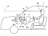
- the HUD device 100 As shown in FIG. 1, the HUD device 100 according to the first embodiment of the present disclosure is mounted on a vehicle 1 that is a kind of moving body and is housed in an instrument panel 2.
- the HUD device 100 projects image display light onto a windshield 3 as a projection member of the vehicle 1.
- HUD device 100 displays a virtual image so that a crew member of vehicles 1 can recognize visually. That is, when the display light reflected by the windshield 3 reaches the visual recognition area EB set in the interior of the vehicle 1, the occupant whose eye point EP is located in the visual recognition area EB uses the display light as a virtual image VI. Perceive.
- the occupant can recognize various information displayed as the virtual image VI. Examples of various information displayed as the virtual image VI include vehicle state values such as vehicle speed and fuel remaining amount, and vehicle information such as road information and visibility assistance information.
- the windshield 3 of the vehicle 1 is formed in a plate shape with translucent glass or synthetic resin.
- the windshield 3 forms a projection surface 3a on which display light is projected in a smooth concave or flat shape.
- a combiner instead of the windshield 3, a combiner separate from the vehicle 1 may be installed in the vehicle 1, and an image may be projected onto the combiner.
- the HUD device 100 itself may include a combiner as a projection member.
- the visual recognition area EB is a spatial area in which the virtual image VI displayed by the HUD device 100 is visible. That is, if the eye point EP is within the visual recognition area EB, the virtual image VI can be visually recognized, and if the eye point EP deviates from the visual recognition area EB, the visual recognition of the virtual image VI becomes extremely difficult.
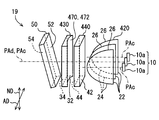
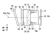
- the HUD device 100 includes a light emitting element array 10, a condenser lens 20, a diverging lens 30, a projection lens 40, an image display panel 50, and a light guide unit 60, which are housed and held in a housing 80. .
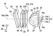
- the light emitting element array 10, the condenser lens 20, the diverging lens 30, the projection lens 40, and the image display panel 50 constitute an image projection unit 19.
- Each member 10, 20, 30, 40 provided in the image projection unit 19 is accommodated in a casing 19a (see FIG. 1) having a light shielding property.
- the light emitting element array 10 has a plurality of light emitting elements 10a as shown in FIGS.
- the plurality of light emitting elements 10a are mounted on a light source circuit board 12 formed in a flat plate shape, and are arranged in the element arrangement direction AD at a predetermined interval.
- the element arrangement direction AD is one direction
- the number of light emitting elements 10a arranged in the light emitting element array 10 is three.
- Each light emitting element 10a is, for example, a light emitting diode element that generates little heat.
- Each light emitting element 10 a is electrically connected to a power source through a wiring pattern on the light source circuit board 12.
- each light emitting element 10a is formed by sealing a chip-like blue light emitting diode element with a yellow phosphor in which a yellow fluorescent agent is mixed with a translucent synthetic resin. The yellow phosphor is excited by blue light emitted according to the amount of current from the blue light emitting diode element to emit yellow light, and pseudo white illumination light is emitted from each light emitting element 10a by the mixture of blue light and yellow light. Be emitted.
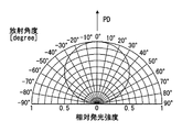
- each light emitting element 10a emits illumination light in a radiation angle distribution in which the emission intensity relatively decreases as the emission intensity deviates from the emission peak direction PD where the emission intensity becomes maximum.
- the light emission peak direction PD of each light emitting element 10a is a direction aligned with a direction perpendicular to the plate surface of the light source circuit board 12. Such illumination light enters the condenser lens 20.
- the condenser lens 20 is disposed on the optical path between the light emitting element array 10 and the image display panel 50, particularly on the optical path between the light emitting element array 10 and the diverging lens 30. Yes.
- the condensing lens 20 is a lens array formed of translucent synthetic resin or glass.
- the incident side surface 22 facing the light emitting element array 10 has a smooth flat shape common to the entire condensing lens 20.
- a plurality of condensing convex surfaces 26 are arranged on the exit side surface 24 of the condensing lens 20 facing the diverging lens 30.
- Each light-convex convex surface 26 is provided so as to individually pair with each light-emitting element 10a.
- the respective converging convex surfaces 26 are provided in the same number (for example, three) as the light emitting elements 10a according to the number of the light emitting elements 10a arranged, and are arranged with each other in the same element arrangement direction AD as the light emitting elements 10a. ing.
- Each condensing convex surface 26 is formed into a smooth convex shape by curving convexly at least in the element arrangement direction AD. Particularly in the present embodiment, each light-convex convex surface 26 is formed in a spherical shape. Each condensing convex surface 26 has substantially the same shape.
- each condensing convex surface 26 constitutes a main axis PAc individually corresponding to the pair of light emitting elements 10a.
- the main axis in the present embodiment means a virtual axis connecting the surface vertex and the center of curvature (for example, the center of curvature defined by the surface vertex).
- the main axis PAc of each light-convex convex surface 26 passes through the paired light emitting elements 10a and extends in a direction substantially coincident with the light emission peak direction PD.
- the condensing lens 20 constitutes a plurality of (for example, three) principal axes PAc that are the same number as the light emitting elements 10a or the condensing convex surfaces 26 in the cross section including the element arrangement direction AD.
- each light emitting element 10a is incident on and refracted mainly by each condensing convex surface 26, and receives an individual condensing action for each condensing convex surface 26.
- the individual condensing action extends, and the illumination light emitted from the condensing lens 20 enters the diverging lens 30.
- a contact receiving portion 28 formed in a planar shape is provided on the exit side surface 24 of the condensing lens 20 on the outer periphery of the arrangement of the condensing convex surfaces 26.
- the contact receiving portion 28 is in contact with a first contact portion 36 of a diverging lens 30 described later.
- a substrate contact portion 29 that protrudes from the incident side surface 22 toward the light source circuit board 12 and contacts the light source circuit board 12 is provided. Yes.
- the diverging lens 30 is disposed on the optical path between the light emitting element array 10 and the image display panel 50, particularly on the optical path between the condenser lens 20 and the projection lens 40.
- the diverging lens 30 is made of translucent synthetic resin or glass.
- the emission side surface 34 facing the projection lens 40 has a smooth flat shape common to the diverging lens 30 as a whole.
- a diverging portion 70 is provided on the incident side surface 32 facing the condenser lens 20.
- the diverging unit 70 has a single refracting surface 72 as a surface that refracts illumination light.
- the refracting surface 72 is formed in a smooth concave shape by curving in a concave shape at least in the element arrangement direction AD.
- the refracting surface 72 has a curvature in the element arrangement direction AD, but has no curvature in the arrangement orthogonal direction ND orthogonal to the element arrangement direction AD, so that it is formed in a cylindrical surface shape. .
- the diameter in the element arrangement direction AD is larger than the sum of the diameters of the respective converging convex surfaces 26.
- the refracting surface 72 is a single surface that collectively refracts illumination light incident from each light emitting element 10a through the pair of condenser lenses 20. That is, the illumination light that has passed through each condensing convex surface 26 is refracted by a single refracting surface 72 that faces each condensing convex surface 26.
- the refracting surface 72 constitutes one principal axis PAd passing through the surface vertex 72a in a section including the element arrangement direction AD (for example, a meridional section including the element arrangement direction AD).
- the main axis PAd of the diverging part 70 is in the center pair of the pair of the light emitting elements 10a and the condensing convex surface 26 arranged in the element arrangement direction AD. It passes through the surface vertex 26a of the light emitting element 10a and the converging convex surface 26.
- one main axis PAd of the diverging part 70 overlaps the central main axis PAc among the plurality of main axes PAc of the light-convex convex surface 26.
- the principal axis PAd substantially coincides with the optical axis, the paraxial and off-axis terms are handled with reference to the principal axis PAd.
- each light emitting element 10a passes through each condensing convex surface 26, and then is diverged in the element arrangement direction AD by the single refracting surface 72 common to each light emitting element 10a.
- the diverging action is applied, and the illumination light emitted from the diverging lens 30 enters the projection lens 40.
- the diverging lens 30 is formed into a plano-concave lens shape as a whole due to the shape of the surfaces 32 and 34 described above. That is, the thickness of the diverging lens 30 gradually increases from the main axis PAd toward the off-axis on both sides of the element arrangement direction AD. Thus, the thickness on both sides of the element arrangement direction AD at the outer edge portion 30a outside the diverging lens 30 is larger than the thickness at the paraxial portion 30b.
- the diverging lens 30 has a shape in which the outer edge portion 30a protrudes toward the light emitting element array 10 side rather than the paraxial portion 30b due to a single concave refracting surface 72 particularly on the light emitting element array 10 side.
- the tip of the protruding outer edge portion 30a is chamfered in a flat shape. Since the tip of the outer edge portion 30a is in contact with the contact receiving portion 28 of the condenser lens 20, the diverging lens 30 is in contact with the condenser lens 20 on the light emitting element array 10 side of the outer edge portion 30a. A contact portion 36 is provided.
- the respective projections projecting toward the refractive surface 72 from the contact receiving portion 28.
- At least a part of the light convex surface 26 is disposed in a space 72 b generated by the concave curvature of the refractive surface 72.
- the converging convex surface 26 does not appear to be disposed in the space 72b, but is actually disposed as shown in FIG.
- the diverging lens 30 on the image display panel 50 side of the outer edge portion 30 a has a second contact portion 38 that contacts the projection lens 40.
- the second contact portion 38 is provided as a protrusion protruding from the emission side surface 34 toward the projection lens 40 at the outer edge portion 30a.
- the second abutting portion 38 has a flat tip end.
- the projection lens 40 is disposed on the optical path between the light emitting element array 10 and the image display panel 50 in FIG. 2, and particularly on the optical path between the diverging lens 30 and the image display panel 50.
- the projection lens 40 is formed of a translucent synthetic resin or glass or the like, and has a substantially flat plate shape as a whole.
- the projection lens 40 is a lens array in which a plurality of divided blocks 40a are integrally formed with each other.
- the plurality of divided blocks 40 a are provided in the same number as the light emitting elements 10 a or the light-convex convex surfaces 26, and are arranged with respect to each other in the element arrangement direction AD, similarly to the light-emitting elements 10 a and the light-convex convex surfaces 26.
- the divided blocks 40a have substantially the same shape.
- a plurality of divided lens surfaces 43 are formed in a striped state.
- the dividing direction of the divided lens surface 43 on the incident side surface 42 is, for example, along the array orthogonal direction ND, and the boundary line between the adjacent divided lens surfaces 43 extends linearly along the element array direction AD. Therefore, in the cross section including the element arrangement direction AD, one divided lens surface 43 is formed across the plurality of divided blocks 40a. In this way, each divided lens surface 43 is formed as one divided region divided into regions by a predetermined divided width Wn.
- a divided convex surface 43a divided into a convex Fresnel lens shape is provided as the divided lens surface 43.
- the divided convex surface 43a is formed based on one virtual convex curved surface Sva defined as a virtual lens surface in the projection lens 40.
- the virtual convex curved surface Sva is curved in the array orthogonal direction ND into a convex shape that is convex toward the light emitting element array 10 side, thereby exhibiting a smooth cylindrical surface shape. Therefore, the incident-side surface 42 exerts a deflection action on the illumination light, which deflects the traveling direction of the illumination light mainly in the array orthogonal direction ND.
- the deflection action is a light collecting action.
- each divided lens surface 45 is formed as one divided region divided into regions by a predetermined divided width Wa.
- the approximate plane 45a is formed based on a virtual convex curved surface Svb defined as a virtual lens surface in the projection lens 40.
- the virtual convex curved surface Svb has a smooth cylindrical surface shape by being curved along the element arrangement direction AD into a convex shape convex toward the image display panel 50 side.
- the approximate plane 45a is formed in a planar shape as an approximate plane obtained by linear interpolation of a plurality of coordinates extracted from the virtual convex curved surface Svb.
- the end coordinates Ce of the virtual convex curved surface Svb at the ends of the divided areas are adopted as the plurality of coordinates, and the gradient of the approximate plane is defined by linear interpolation between the end coordinates Ce.
- the virtual convex curved surface Svb appears on the exit-side surface 44 in a state of being flat by partial approximation.
- the anisotropic deflection plane 45b is arranged in a state of being interposed between the approximate planes 45a.
- the anisotropic deflection plane 45b is formed based on a virtual inclined surface Ssb defined as a virtual lens surface in the projection lens 40.
- the virtual inclined surface Ssb is composed of a plurality of planar inclined surfaces Ssp that change in reverse gradient at locations corresponding to the surface vertices of the virtual convex curved surface Svb in the cross section including the element arrangement direction AD.
- the slope of each planar slope Ssp is set to be opposite to the slope of the corresponding portion of the virtual convex curved surface Svb.
- six divided lens surfaces 45 are set for one divided block 40a.
- the six divided lens surfaces 45 are arranged in the order of the approximate plane 45a, the anisotropic deflection plane 45b, the approximate plane 45a, the approximate plane 45a, the anisotropic deflection plane 45b, and the approximate plane 45a, and the boundary between the adjacent approximate planes 45a. Is a portion corresponding to the surface vertex of the virtual convex curved surface Svb. In FIG. 6, the reference numerals are given only to some of the corresponding elements.
- the exit side surface 44 exerts a deflection action on the illumination light, which deflects the traveling direction of the illumination light mainly in the element arrangement direction AD.
- the illumination light refracted by the approximate plane 45a has a deflecting action in the same direction as a normal convex condensing action as a deflecting action. Therefore, the deflecting action can be said to be a substantial condensing action.
- Illumination light refracted by the anisotropic deflection plane 45b is subjected to a deflection action opposite to that of the adjacent approximate plane 45a as a deflection action.
- the illumination light that has been deflected in the opposite direction by the anisotropic deflection plane 45b is mixed with the illumination light that has been deflected by the approximate plane 45a.
- the projection lens 40 having such a complicated shape, it is difficult to define one main axis itself, and it is substantially multiaxial.
- the illumination light emitted from the projection lens 40 in this way enters the image display panel 50.
- a contact receiving portion 48 formed in a planar shape is formed on the outer periphery of the divided block 40a.
- the contact receiving portion 48 is in contact with the second contact portion 38 of the diverging lens 30.
- the image display panel 50 is a liquid crystal panel using thin film transistors (TFTs), and is an active matrix formed from a plurality of liquid crystal pixels 50a arranged in two dimensions, for example.
- TFTs thin film transistors
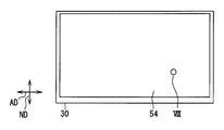
- the image display panel 50 has a rectangular shape having a longitudinal direction and a short direction.
- the longitudinal direction is along the element arrangement direction AD.
- the liquid crystal pixels 50a are arranged in the longitudinal direction and the short direction, so that the display surface 54 that emits an image as display light on the light guide unit 60 side also has a rectangular shape.
- Each liquid crystal pixel 50a is provided with a transmissive portion 50b provided so as to penetrate in the normal direction of the display surface 54, and a wiring portion 50c formed so as to surround the transmissive portion 50b.
- the image display panel 50 has a flat plate shape by being formed by laminating a pair of polarizing plates and a liquid crystal layer sandwiched between the pair of polarizing plates.
- Each polarizing plate has a property of transmitting light polarized in a predetermined direction and absorbing light polarized in a direction perpendicular to the predetermined direction.
- the pair of polarizing plates has the predetermined direction orthogonal to each other. Has been placed.
- the liquid crystal layer can rotate the polarization direction of light incident on the liquid crystal layer in accordance with the applied voltage by applying a voltage for each liquid crystal pixel. By rotating the polarization direction, the ratio of light transmitted through the subsequent polarizing plate, that is, the transmittance can be changed.
- the image display panel 50 controls the transmittance of each liquid crystal pixel 50a with respect to the incidence of illumination light on the illumination target surface 52 that is the surface on the light emitting element array 10 side. That is, the image display panel 50 can form an image corresponding to illumination by illumination light and emit it as display light.
- Adjacent liquid crystal pixels 50a are provided with color filters of different colors (for example, red, green, and blue), and various colors are realized by combining these color filters.
- the image display panel 50 displays the light emission peak direction PD immediately after emission from the light emitting element array 10, the directions of the main axes PAc and PAd, and the thickness direction of the projection lens 40 as shown in FIG.
- the surface 54 is inclined so that the normal direction of the surface 54 intersects. Since the display surface 54 of the image display panel 50 is exposed from the casing 19 a of the image projection unit 19, the image projection unit 19 projects display light onto the light guide unit 60.
- the light guide unit 60 guides display light from the image display panel 50 to the windshield 3 as shown in FIG.
- the light guide unit 60 of the present embodiment has a plane mirror 61 and a concave mirror 63. In the present embodiment, display light from the image display panel 50 first enters the plane mirror 61.
- the flat mirror 61 is formed by evaporating aluminum as the reflective surface 62 on the surface of a base material made of synthetic resin or glass.
- the reflection surface 62 is formed in a smooth flat shape.
- the display light incident on the plane mirror 61 is reflected by the reflecting surface 62 toward the concave mirror 63.
- the concave mirror 63 is formed by evaporating aluminum as the reflecting surface 64 on the surface of a base material made of synthetic resin or glass.
- the reflecting surface 64 is formed in a smooth concave shape by being curved in a concave shape.
- the display light incident on the concave mirror 63 is reflected toward the windshield 3 by the reflecting surface 64.
- a window portion 81 is provided in the housing 80 between the concave mirror 63 and the windshield 3.
- the window 81 is covered with a translucent dustproof cover 82. Therefore, the display light from the concave mirror 63 passes through the dust cover 82 and enters the windshield 3. Thus, the display light reflected by the windshield 3 reaches the visual recognition area EB, and the occupant can visually recognize the virtual image VI.
- the virtual image VI is magnified from the display surface 54 by the enlargement action by the concave mirror 63 of the light guide 60 and the enlargement action by the windshield 3 when the projection surface 3a of the windshield 3 is curved. In the state, it is visually recognized by the passenger.
- the entrance pupil position ENP shown in FIG. 9 is moved from the image display panel 50 to the light emitting element array 10 side due to the side effect of the virtual image VI enlargement by the light guide unit 60 and the windshield 3. It exists at a position separated by a predetermined distance. If the HUD device 100 is not provided with the diverging unit 70 and illumination with enhanced telecentricity is performed by the condenser lens 20 and the projection lens 40, the occupant's eye point EP moves from the center to the end of the visual recognition area EB. Then, the luminance of the visible virtual image VI can be rapidly reduced.
- the diverging action of the diverging unit 70 the emission peak direction PD of the illumination light emitted from each light emitting element 10a is adjusted to the direction away from the position ENP of the entrance pupil, thereby suppressing such a decrease in luminance.
- Such a diverging action corresponds to the positional relationship between the light emitting element 10a and the main axis PAd. Specifically, the light-emitting element 10a that is farther from the main axis PAd is refracted on the refracting surface 72 toward the off-axis side. Further, the radiation angle of the illumination light from each light emitting element 10a is widened by the diverging action.
- the overlap of the illumination light from each light emitting element 10a in the narrow range of the paraxial is adjusted. Since the illumination light from each light emitting element 10a is widely distributed off-axis, a decrease in the brightness of the virtual image VI at the end of the viewing area EB is suppressed.
- each light emitting element 10a when the diverging part 70 is not provided by a broken line is shown, and each light emitting element when the diverging action of the diverging part 70 is received by a solid line
- the light emission peak direction PD and the range of illumination light from 10a are shown.
- the image display panel 50 corresponds to an “image forming unit”
- the diverging lens 30 corresponds to an “optical member” having a diverging unit 70
- the condenser lens 20 from the light emitting element array 10 side.
- the projection lens 40 guides the illumination light from the diverging lens 30 side to the image display panel 50 side.
- member corresponds to “member”.
- the diverging lens 30 disposed on the optical path between the light emitting element array 10 and the image display panel 50 includes the diverging unit 70.
- the diverging unit 70 exerts a diverging action on the illumination light from the plurality of light emitting elements 10 a arranged in the element arrangement direction AD.
- the illumination light emitted from each light emitting element 10a is subjected to a diverging action in the element arrangement direction AD, whereby the overlapping state of the illumination light emitted from each light emitting element 10a can be adjusted.
- the diverging unit 70 has a refracting surface 72 that constitutes one principal axis PAd in a cross section including the element arrangement direction AD.
- the overlapping state of the illumination light emitted from each light emitting element 10a is as follows. It can be adjusted according to the arrangement interval of the light emitting elements 10a.
- the light amount is suppressed from being concentrated in a narrow range, and the display light easily reaches a wide range.
- the refracting surface 72 is a single surface that is concavely curved in the element arrangement direction AD and refracts the illumination light collectively. Since the illumination light from each light emitting element 10a receives a diverging action by a single surface curved in a concave shape, the overlapping state of the illumination light emitted by each light emitting element 10a can be adjusted reliably. Therefore, the display light easily reaches a wide range.
- the single refracting surface 72 is formed in a cylindrical surface shape that is concavely curved along one element arrangement direction AD. In this way, it is possible to suppress the diverging action from extending in the array orthogonal direction ND in which the light emitting elements 10a are not arrayed. Accordingly, it is possible to suppress a loss of illumination to the image display panel 50 in the array orthogonal direction ND in which the illuminance tends to be insufficient.
- the outer edge portion 30a has a thick shape.
- the diverging lens 30 utilizes the thickness of the outer edge part 30a by concave lens shape, and the image display panel 50 is among the 1st contact parts 36 contacted with the condensing lens 20 in the light emitting element array 10, and the outer edge part 30a.
- a second abutting portion 38 that abuts the projection lens 40 on the side. Accordingly, since the outer edge portion 30a of the diverging lens 30 can function as a spacer between the condenser lens 20 and the projection lens 40, the relative positional deviation of each member 20, 30, 40 is restricted, and image display is performed. Stable lighting to the panel 50 can be realized. As described above, the visibility of the virtual image VI can be stabilized.
- each light-convex convex surface 26 is arranged in a space 72b generated by the concave curvature of the refractive surface 72.
- the second embodiment of the present disclosure is a modification of the first embodiment.
- the second embodiment will be described with a focus on differences from the first embodiment.
- the diverging lens 230 in the second embodiment is on the optical path between the light emitting element array 10 and the image display panel 50, particularly on the optical path between the condenser lens 20 and the projection lens 40.
- the diverging lens 230 is formed of a translucent synthetic resin or glass or the like, and has a substantially flat plate shape as a whole.
- the exit side surface 34 facing the projection lens 40 has a smooth planar shape.
- a diverging part 270 is provided on the incident side surface 32 facing the condenser lens 20.
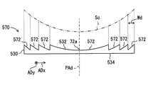
- the diverging unit 270 has a plurality of refracting surfaces 272 that are arranged with respect to the element arrangement direction AD as surfaces that refract illumination light.
- the plurality of refractive surfaces 272 are formed in a state of being divided into stripes.
- the dividing direction of the refracting surface 272 on the incident side surface 32 is along the element array direction AD, and the boundary line between the adjacent refracting surfaces 272 extends linearly along the array orthogonal direction ND. In this way, each refracting surface 272 is formed as one divided region divided into regions by a predetermined divided width Wd.
- the plurality of refractive surfaces 272 of the present embodiment are formed based on one virtual concave curved surface Sc defined as a virtual lens surface in the diverging lens 230, and the virtual concave curved surface Sc is divided into concave Fresnel lens shapes. It has become a thing.
- the virtual concave curved surface Sc exhibits a smooth cylindrical surface shape by being curved in the element arrangement direction AD into a concave shape which is concave on the side opposite to the condenser lens 20.
- the virtual concave curved surface Sc constitutes one main axis PAd substantially orthogonal to the arrangement direction of the refracting surfaces 272 in a section including the element arrangement direction AD (for example, a meridional section including the element arrangement direction AD).
- the plurality of refracting surfaces 272 appear on the incident-side surface 32 by shifting the virtual concave curved surface Sc in the extending direction of the main axis PAd for each divided width Wd.
- the diverging unit 270 uses the refractive surfaces 272 to cause the respective refractive surfaces. It can be said that one common spindle PAd is formed between the 272. As the plurality of refractive surfaces 272 cooperate, the divergence unit 270 exerts the same divergence action as that of the first embodiment on the illumination light incident from each light emitting element 10a through the pair of converging convex surfaces 26. It has become.
- the plurality of refracting surfaces 272 arranged in alignment with the element arrangement direction AD collectively exert a diverging action.
- the diverging part 270 can be made compact with respect to the extending direction of the main axis PAd, so that the visibility of the virtual image VI can be improved while suppressing an increase in the physique.
- the diverging lens 230 corresponds to an “optical member” having the diverging portion 270.
- the third embodiment of the present disclosure is a modification of the first embodiment.
- the third embodiment will be described with a focus on differences from the first embodiment.
- the condenser lens 20 and the diverging lens 30 are not provided, but a diverging condenser lens 320 is provided instead.
- the divergent condensing lens 320 is disposed on the optical path between the light emitting element array 10 and the image display panel 50, particularly on the optical path between the light emitting element array 10 and the projection lens 40.
- the diverging condensing lens 320 is formed of a light-transmitting synthetic resin or glass.
- a diverging portion 370 is provided on the incident side surface 322 facing the light emitting element array 10.
- the divergence part 370 has the single refractive surface 372 similar to the divergence part 70 in the divergent lens 30 of 1st Embodiment.
- a plurality of condensing convex surfaces 326 similar to those of the condensing lens 320 of the first embodiment are arrayed on the exit side surface 324 facing the projection lens 40.
- the illumination light from each light emitting element 10a is subjected to a diverging action by the refracting surface 372 of the diverging unit 370. Thereafter, the illumination light from each light emitting element 10a is mainly incident on each pair of condensing convex surfaces 326 and receives an individual condensing action for each condensing convex surface 326. The diverging action and the individual condensing action are applied, and the illumination light emitted from the diverging condensing lens 320 enters the projection lens 40.
- the diverging unit 370 having a single refracting surface 372 that constitutes one principal axis PAd in the cross section including the element arrangement direction AD is provided for the illumination light from each light emitting element 10a.
- a diverging action is exerted in the element arrangement direction AD. Therefore, it is possible to achieve the operational effects according to the first embodiment.
- the condensing convex surface 326 is formed as a surface on one side, more specifically, as the exit side surface 324, and the diverging part 370 is the same as the exit side surface 324. It is formed as the opposite incident side surface 322.
- the diverging condensing lens 320 corresponds to an “optical member” having a diverging portion 370.
- the fourth embodiment of the present disclosure is a modification of the first embodiment.
- the fourth embodiment will be described with a focus on differences from the first embodiment.
- the projection lens 440 in the fourth embodiment is disposed on the optical path between the condenser lens 420 and the diverging lens 430, in particular.
- the diverging lens 430 is disposed on the optical path between the projection lens 440 and the image display panel 50 in particular.
- the condenser lens 420 and the projection lens 440 are arranged on the optical path between the light emitting element array 10 and the image display panel 50.
- the exit side surface 34 facing the image display panel 50 has a smooth planar shape.
- a diverging portion 470 is provided on the incident side surface 32 of the diverging lens 430 that faces the projection lens 440.
- the divergence part 470 has the single refracting surface 472 similar to the divergence part 70 in the diverging lens 30 of the first embodiment.
- the illumination light from each light emitting element 10a enters the diverging lens 430 through the condenser lens 420 and the projection lens 440.
- the diverging unit 470 of the diverging lens 430 exerts a diverging action on the illumination light that has been condensed by the condensing lens 420 and the projection lens 440 in the element arrangement direction AD immediately before the image display panel 50 is illuminated.
- the illumination light emitted from the diverging lens 430 in this way enters the image display panel 50.
- the diverging part 470 having a single refracting surface 472 constituting one principal axis PAd in the cross section including the element arrangement direction AD is provided for the illumination light from each light emitting element 10a.
- a diverging action is exerted in the element arrangement direction AD. Therefore, it is possible to achieve the operational effects according to the first embodiment.
- the diverging unit 470 exerts a diverging action on the illumination light collected by the condensing lens 420 and the projection lens 440 immediately before the illumination on the image display panel 50. Since it is suppressed that the one part illumination light which received the diverging effect will diverge outside the image display panel 50, the efficiency of illumination can be improved.
- the diverging lens 430 corresponds to an “optical member” having the diverging portion 470, and the condensing lens 420 and the projection lens 440 are combined to collect the illumination light from each light emitting element 10a.
- a “light collecting portion” that exerts a light action is configured.
- the fifth embodiment of the present disclosure is a modification of the first embodiment.
- the fifth embodiment will be described with a focus on differences from the first embodiment.
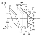
- the light-emitting element array 510 of the fifth embodiment has a plurality of light-emitting elements 510a on the light source circuit board 12, as shown in FIG. As shown in FIG. 16, the plurality of light emitting elements 510a are arranged in a matrix in two element arrangement directions ADx and ADy at predetermined intervals. In the present embodiment, the number of light emitting elements 510a arranged in the light emitting element array 510 is five in the direction ADx and four in the direction ADy, that is, a total of 20 pieces of 5 ⁇ 4.
- a condenser lens 520, a diverging lens 530, and a projection lens 540 are disposed between the light emitting element array 510 and the image display panel 550.
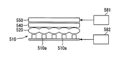
- the light emitting element array 510, the condenser lens 520, the diverging lens 530, the projection lens 540, the image display panel 550, and the like constitute an image projection unit 519 that projects an image.
- Each member 510, 520, 530, 540, 550 provided in the image projection unit is accommodated in a light shielding casing 19a.
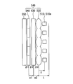
- the condensing lens 520, the diverging lens 530, and the projection lens 540 constitute a backlight optical system 549.
- the condensing lens 520 is a lens array similar to that of the first embodiment, but the plurality of converging convex surfaces 26 are arranged in two directions ADx in accordance with the light emitting elements 510a being arranged in two directions ADx and ADy. , ADy are arranged.
- the cylindrical concave concave surface Sc is substantially orthogonal to the extending direction of the generatrix on the incident-side surface 532, as in the diverging lens of the second embodiment.
- a plurality of refractive surfaces 572 are formed in a concave Fresnel lens shape divided in the direction.
- the virtual concave curved surface Sc is divided into a specific direction ADx in which the number of arranged light emitting elements is large (that is, five) out of the two element arrangement directions ADx and ADy.
- the diverging unit 570 has a plurality of refracting surfaces 572 arranged as a surface that refracts illumination light in accordance with one specific direction ADx. Since the centers of curvature of the plurality of refracting surfaces 572 exist on a common principal axis PAc, it can be said that the divergence unit 570 constitutes a common principal axis PAc between the refracting surfaces 572.
- a plurality of refracting surfaces 572 jointly exert a diverging action in a specific direction ADx out of the two element arrangement directions ADx and ADy with respect to illumination light incident from each light emitting element 510a through the pair of converging convex surfaces 26. Effect.
- the projection lens 540 is a lens array in which a plurality of divided blocks 40a are integrally formed with each other.
- a plurality of divided blocks 40a are arranged in two directions in accordance with the light emitting elements 510a being arranged in two directions. That is, a total of 20 divided blocks 40a of 5 ⁇ 4 are provided.
- a plurality of divided lens surfaces 543 are formed in a striped state.
- the dividing direction of the divided lens surface 543 on the incident-side surface 542 is along the specific direction ADx of the two directions, and the boundary line between the adjacent divided lens surfaces 543 extends linearly along the direction ADy. Therefore, in the cross section including the direction ADy, one divided lens surface 543 is formed across a plurality (specifically, four) of divided blocks 40a corresponding to the number of arranged light emitting elements 510a in the direction ADy.
- a plurality of approximate planes 543a and a plurality of anisotropic deflection planes 543b are provided in the same manner as the surfaces 45a and 45b of the first embodiment.
- a plurality of divided lens surfaces 545 are formed in a striped state.
- the dividing direction of the divided lens surface 545 on the exit-side surface 544 is along the direction ADy of the two directions, and the boundary line between the adjacent divided lens surfaces 545 extends linearly along the specific direction ADx.
- one divided lens surface 545 is formed across a plurality (specifically, five) of divided blocks 40a corresponding to the number of arrayed light emitting elements 510a in the direction ADx.
- a plurality of approximate planes 545a and a plurality of anisotropic deflection planes 545b are provided in the same manner as the surfaces 45a and 45b of the first embodiment.
- the projection lens 540 having such a complicated shape, it is difficult to define one main axis, and it is substantially multiaxial. If it is considered that the approximate planes 543a and 545a exert a substantial light collecting action, it can be considered that the number of divided blocks 40a (ie, 20) main axes are provided by the aggregate of the approximate planes 543a and 545a. .
- the optical power of the projection lens 540 that can be calculated using the virtual convex curved surface Svb that is the basis of the approximate planes 543a and 545a of the projection lens 540 is ⁇ 1 (> 0), the divergence.
- the optical power of the lens 530 is defined as ⁇ 2 ( ⁇ 0)
- the optical power of the condensing lens 520 that can be calculated using the condensing convex surface 26 of the condensing lens 520 is defined as ⁇ 3 (> 0).
- an interval between the position of the main point of the projection lens 540 and the position of the main point of the diverging lens 530 is defined as e1
- an interval between the main point of the diverging lens 530 and the main point of the condenser lens 520 is defined as e2.
- the position of each principal point may be considered by replacing it with a principal plane that is a virtual plane including the principal point.
- the position of the entrance pupil ENP (see also the schematic diagram of FIG. 9) is located farther from the image display panel 550 than the position of the principal point of the projection lens 540, and each light emitting element is connected to the entrance pupil ENP.
- the distance ⁇ from the principal point of the condenser lens 520 to the light emitting element array 510 is: 0 ⁇ ⁇ L (Expression 2) Meet the conditions.
- the light emitting element array 510 is disposed between the position of the principal point of the condensing lens 520 and the position of the synthetic focus on the opposite side of the image display panel 550 of the backlight optical system 549. .
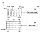
- the HUD device 500 of this embodiment includes an image generation unit 581 and an individual light emission control unit 582 as components of the image projection unit 519.
- the image generation unit 581 and the individual light emission control unit 582 are constructed as functional blocks realized by the control circuit 580.
- the control circuit 580 is an electronic circuit having at least one processor, for example, a memory such as a ROM and a RAM, and an input / output interface.
- the processor implements the functions of the image generation unit 581 and the individual light emission control unit 582 by executing a computer program stored in a memory, for example.
- the control circuit 580 can communicate with the image display panel 550, each light emitting element 510a of the light emitting element array 510, and an external device via an input / output interface.
- the control circuit 580 may be provided in common between the image generation unit 581 and the individual light emission control unit 582, or may be provided separately. In the present embodiment, the control circuit is housed in the housing 80, but may be disposed outside the housing 80.
- the image generation unit 581 generates image data to be displayed on the display surface 54 of the image display panel 550. Specifically, the image generation unit 581 generates image data based on information input as an electrical signal from an external device. For example, when the speed of the vehicle is input from an external device, the image generation unit 581 generates image data indicating the speed to be displayed on at least a part of the display surface 54.
- the image data in the present embodiment is, for example, data indicating RGB values (256-level gradation values) for each unit of the liquid crystal pixel 50a (see also FIG. 8).
- An electrical signal based on the image data of the image generation unit 581 is output to the image display panel 550, whereby the transmittance of each liquid crystal pixel 50a of the image display panel 550 is controlled.
- the individual light emission control unit 582 controls each light emitting element 510a to individual light emission intensity corresponding to the image data generated by the image generation unit 581.
- a display divided region 54a is defined in which the entire region of the display surface 54 of the image display panel 550 is divided by the number of arranged light emitting elements 510a arranged in the element arranging directions ADx and ADy. That is, the display surface 54 is virtually divided into a total of 20 display divided areas 54a of 5 ⁇ 4, and each display divided area 54a and the light emitting element 510a that mainly illuminates the display divided area 54a are individually provided. Is associated with.
- the individual light emission control unit 582 determines and controls the light emission intensity of the light emitting element 510a corresponding to the area 54a with reference to the image data corresponding to the area 54a for each display divided area 54a. . For example, the individual light emission control unit 582 turns off the light emitting element 510a corresponding to the display divided region 54a in which the image based on the image data generated by the image generation unit 581 is not displayed among the light emitting elements 510a. In more detail, the individual light emission control unit 582 determines whether or not there is an image to be displayed in the display divided area 54a for each display divided area 54a. Then, the light emitting element corresponding to the display divided area 54a where there is no image to be displayed, that is, non-display is turned off.
- Whether or not an image to be displayed exists in the display divided area 54a refers to, for example, the RGB value of the unit of each liquid crystal pixel 50a in the display divided area 54a in the image data. Specifically, when all the RGB values in a certain display divided area 54a are gradation values of (0, 0, 0) indicating black, there is no image displayed in the display divided area 54a. judge. As another method, if all of the RGB values (X, Y, Z) in a certain display divided area 54a are less than or equal to a predetermined value, an image displayed in the display divided area 54a is displayed. A method of determining that it does not exist may be employed. As another method, if all the RGB values in a certain display divided area 54a are the same value, a method of determining that there is no image displayed in the display divided area 54a may be employed.
- step S10 the image generation unit 581 generates image data. After the process of step S10, the process proceeds to step S20.
- step S20 the individual light emission control unit 582 determines whether there is an image to be displayed in each display division area 54a. After the process of step S20, the process proceeds to step S30.
- step S30 the individual light emission control unit 582 turns off the light emitting element 510a corresponding to the display divided area 54a where the image is not displayed.
- the image generation unit 581 rewrites the image displayed on the image display panel 550. As described above, a series of processing is completed.
- the individual light emission control unit 582 also adjusts the light emission intensity of the light emitting element 510a corresponding to the display divided area 54a even in the display divided area 54a where the image to be displayed exists. That is, in addition to controlling the transmittance of each liquid crystal pixel 50a of the image display panel 550, the light emission intensity of each light emitting element 510a is adjusted, so that the dynamic range of display light from the image display panel 550 (that is, display light) is adjusted. The ratio of the minimum luminance value to the maximum luminance value) is enlarged, and the expressive power of the virtual image VI is increased.
- the diverging part 570 having a plurality of refracting surfaces 572 constituting one principal axis PAd in the cross section including the specific direction ADx is specified for the illumination light from each light emitting element 510a. It has a diverging effect in the direction ADx. Therefore, it is possible to achieve the operational effects according to the first embodiment.
- the diverging lens 530 disposed on the optical path between the light emitting element array 510 and the image display panel 550 includes the diverging unit 570.
- the diverging unit 570 exerts a diverging action in a specific direction ADx on the illumination light from the plurality of light emitting elements 510a arrayed with each other.
- the illumination light emitted from each light emitting element 510a is diverged in the specific direction ADx, the overlapping state of the illumination lights emitted from each light emitting element 510a can be adjusted.
- the display light of the image formed according to the illumination by the illumination light on the image display panel 550 when the overlap is adjusted so as to suppress the light amount from being concentrated in a narrow range, the display light is wide. It becomes easy to reach the range. As described above, it is possible to suppress a decrease in luminance of the virtual image VI when the occupant moves the head more greatly, and it is possible to improve the visibility of the virtual image VI.
- the diverging unit 70 has the refracting surface 572 that constitutes one principal axis PAd in a cross section including the specific direction ADx. Since the illumination light from each light emitting element 510a is subjected to a diverging action based on the positional relationship between the corresponding light emitting element 510a and one main axis PAd, the overlapping state of the illumination light emitted from each light emitting element 510a is as follows. Therefore, it can be adjusted according to the arrangement interval of the light emitting elements 510a.
- the diverging lens 530 forms a plurality of refractive surfaces 572 in a concave Fresnel lens shape obtained by dividing a cylindrical concave concave curved surface Sc in a specific direction, and the plurality of refractive surfaces 572 cooperate.
- the diverging part 570 can be configured compactly with respect to the extending direction of the main axis PAd, the visibility of the virtual image VI can be enhanced while suppressing an increase in the physique.
- the divergence action is exerted only in the direction in which the occupant moves the head frequently, and the diverging action in the direction with less frequency can be suppressed to suppress the decrease in luminance of the virtual image VI. Will be even higher.
- the specific direction ADx on which the diverging action is exerted is a direction corresponding to the left-right direction of the vehicle on the horizontal plane in the visually recognized virtual image VI. That is, when the occupant moves his / her head in the left-right direction, the effect of the diverging action can be enjoyed.
- each light emitting element 510a is controlled to individual light emission intensity, the light emitting element 510a corresponding to the non-display area of the image on the image display panel 550 is dimmed or turned off, and the virtual image VI.
- the contrast can be improved and the power consumption can be reduced, and the dynamic range of the display light from the image display panel 550 can be expanded.
- the light emitting elements 510a corresponding to the display divided regions 54a in which the image is not displayed are turned off. Such turn-off can reduce the power consumption and improve the contrast of the virtual image VI with the region displaying the image and increase the visibility of the virtual image VI.
- the light emitting element array 510 is the main point of the condensing lens 520 disposed at the position farthest from the image display panel 550 among the members 520, 530, 540 of the backlight optical system 549. And the position of the synthetic focal point of the backlight optical system 549.
- the display positions on the image display panel 550 are increased while increasing the luminance of the virtual image VI visually recognized in the visual recognition area EB. An unintended luminance difference when comparing (for example, the pixels 50a) can be reduced. Therefore, the visibility of the virtual image VI can be improved.
- the image display panel 550 corresponds to an “image forming unit”
- the diverging lens 530 corresponds to an “optical member” having a diverging unit 570.
- the sixth embodiment of the present disclosure is a modification of the fifth embodiment.
- the sixth embodiment will be described with a focus on differences from the fifth embodiment.
- the diverging lens 630 of the sixth embodiment has a plurality of refractive surfaces formed in a concave Fresnel lens shape in which a spherical virtual concave curved surface Sc2 is concentrically divided on the incident-side surface 632 thereof.
- a central refracting surface 672a that overlaps with the center of the display surface of the image display panel and includes the surface vertex has a circular shape.
- the other refracting surface 762b has an annular shape or a partial annular shape.
- the virtual concave curved surface Sc2 in the present embodiment is curved in a concave shape that is concave on the side opposite to the condensing lens 520, thereby exhibiting a smooth spherical shape.
- the diverging unit 670 has a plurality of refracting surfaces 672 arranged concentrically as surfaces for refracting illumination light. Since the centers of curvature of the plurality of refracting surfaces 672 exist on a common principal axis PAd, it can be said that the divergence unit 670 constitutes a common principal axis between the refracting surfaces 672.
- the plurality of refracting surfaces 672 jointly exert a diverging action on each of the two element arrangement directions ADx and ADy with respect to the illumination light incident from the respective light emitting elements 510a through the pair of converging convex surfaces 26.
- the diverging unit 670 having a plurality of refracting surfaces 672 constituting one principal axis PAd in a cross section including two specific directions ADx and ADy in the element arrangement direction is provided for each light emission.
- a diverging action is exerted on the illumination light from the element 510a in specific directions ADx and ADy. Therefore, it is possible to achieve the operational effects according to the first embodiment.
- the diverging lens 630 forms a plurality of refractive surfaces 672 in a concave Fresnel lens shape obtained by concentrically dividing the spherical virtual concave curved surface Sc2, and the plurality of refractive surfaces 672 cooperate.
- the diverging part 670 can be configured compactly with respect to the extending direction of the main axis PAd, the visibility of the virtual image VI can be enhanced while suppressing an increase in the physique.
- the display light can easily reach a wide range when the overlapping state is adjusted in each direction.
- the diverging lens 630 corresponds to an “optical member” having a diverging portion 670.
- the single refracting surface 72 may be any one as long as it constitutes one principal axis PAd in a cross section including the element arrangement direction AD.
- a shape may be employed.
- the refracting surface 72 may be formed in a spherical shape by curving in a concave shape also in the array orthogonal direction ND.
- an aspherical surface including a parabolic surface having rotational symmetry with respect to the main axis PAd may be employed.
- an anamorphic surface such as a toroidal surface may be adopted as the refractive surface 72.
- the center of curvature defined by the coordinates of the refracting surface 72 other than the surface vertex 72a is not located far away from the principal axis PAd with respect to the principal axis PAd that can be defined using the surface vertex 72a of the refractive surface 72, It is assumed that the refracting surface 72 constitutes one main axis PAd.
- the contact receiving portion 28 of the condenser lens 20 may be formed as a protrusion.
- the sag amount at the first contact portion 36 of the single refracting surface 72 is smaller than the sag amount at the outer peripheral edge of the light converging convex surface 26. Therefore, in order to bring the first contact portion 36 and the contact receiving portion 28 of the condensing lens 20 into contact without bringing the refractive surface 72 and the light collecting convex surface 26 into contact, the contact receiving portion 28 is It is provided as a protrusion protruding toward the diverging lens 30 side.
- various shapes can be employed as the projection lens 40.
- a convex Fresnel lens, a normal convex lens, or the like may be employed as the projection lens 40.
- the HUD device 100 may not include at least one of the condenser lens 20 and the projection lens 40.
- the image display panel 50 has a display surface 54 with respect to the emission peak direction PD immediately after emission from the light emitting element array 10, the directions of the main axes PAc and PAd, and the plate thickness direction of the projection lens 40. You may arrange
- the light guide 60 may be configured only by the concave mirror 63, and may have a convex mirror instead of the plane mirror 61.
- the light emitting element 10a may be arranged in a plurality of element arrangement directions AD (for example, two directions).
- the divergence unit 70 has at least a main axis PAd in a cross section including one specific direction among the plurality of element arrangement directions AD. It is possible to suppress a decrease in luminance of the virtual image VI when the head is moved more greatly.
- the refracting surface 72 of the diverging unit 70 may be provided as the exit-side surface 34 of the diverging lens 30 so as to face the incident-side surface 42 of the projection lens 40.
- the incident-side surface 42 may have a condensing convex surface that condenses the illumination light by being curved in a convex shape in the element arrangement direction AD.
- at least a part of the light-convex convex surface may be disposed in a space 72 b generated by the concave curve of the refractive surface 72.
- the diverging unit 70 or 570 is recognized as having a diverging action on the illumination light from the light emitting element 10a or 510a in any one of the element arrangement directions AD or ADx and ADy as a whole.
- the diverging part 70 or 570 may include a refracting surface 72 or 572 or a part of the refracting surface 72 or 572 that is hardly recognized as constituting one main axis PAd.
- the diverging action in the present disclosure means an action of spreading a light beam by applying a negative optical power or the like, and is different from a diffusing action in which light is scattered in various directions by a random element such as a diffusion plate.
- the individual light emission control unit 582 uses the light emission intensity of the light emitting element 510a corresponding to the display divided region 54a in which the image is not displayed among the light emitting elements 510a. You may make it control smaller than the emitted light intensity of the light emitting element 510a corresponding to the display division area 54a displayed.
- the HUD device 100 may include an image generation unit 581 and an individual light emission control unit 582 similar to those of the fifth embodiment. Also in the HUD device 100, as in the fifth embodiment, the HUD device 100 is disposed between the position of the principal point of the condensing lens 20 and the position of the composite focus of the members 10, 20, and 30 constituting the backlight optical system. It is preferable that
- the image projection unit 519 may be configured by a light emitting element array 510, a condenser lens 520, an image display panel 550, and the like.
- the image projection unit 519 may include a light emitting element array 510, a projection lens 540, an image display panel 550, and the like.
- the image projection unit 519 may include a light emitting element array 510, a condenser lens 520, a projection lens 540, an image display panel 550, and the like.
- the present disclosure may be applied to various moving bodies (transportation equipment) such as ships or airplanes other than the vehicle 1.
- the head-up display device is mounted on the moving body 1 and projects and reflects the image display light onto the projection member 3 to display a virtual image so that the occupant can visually recognize the image.
- the head-up display device includes a light-emitting element array 510 in which a plurality of light-emitting elements 510a that emit illumination light are arranged in a plurality of element arrangement directions ADx and ADy.
- the head-up display device further includes an image forming unit 550 that forms an image according to illumination by illumination light and emits the image as display light.
- the head-up display device is disposed on an optical path between the light emitting element array and the image forming unit, and exerts a diverging action on illumination light from each light emitting element in at least one specific direction among a plurality of element arrangement directions.
- Optical members 570 and 670 having diverging portions 570 and 670 are further provided.
- the diverging part has one or more refractive surfaces 572 and 672 that refract illumination light while exerting a diverging action.
- the optical member disposed on the optical path between the light emitting element array and the image forming unit has the diverging unit.
- the divergence part exerts a divergence action on illumination light from a plurality of light emitting elements arranged in a specific direction in a plurality of element arrangement directions.
- the illumination light emitted from each light emitting element receives a diverging action in a specific direction, the overlapping state of the illumination light emitted from each light emitting element can be adjusted.
- the display light of the image formed according to the illumination by the illumination light in the image forming unit when the overlap is adjusted so as to suppress the light amount from being concentrated in a narrow range, the display light is in a wide range. It becomes easy to reach. As described above, it is possible to suppress a decrease in the brightness of the virtual image when the occupant moves the head more greatly, and it is possible to improve the visibility of the virtual image.
- one or more refracting surfaces constitute one main axis PAd in a cross section including a specific direction.
- the illumination light from each light emitting element is subjected to a diverging action based on the positional relationship between the corresponding light emitting element and one main axis.
- the degree of overlap can be adjusted according to the arrangement interval of the light emitting elements.
- the head-up display device is mounted on the moving body 1 and projects and reflects the image display light on the projection member 3 to display a virtual image so that the occupant can visually recognize the image.
- the head-up display device includes a light-emitting element array 10 in which a plurality of light-emitting elements 10a that emit illumination light are arranged in the element arrangement direction AD.
- the head-up display device further includes an image forming unit 50 that forms an image according to illumination by illumination light and emits the image as display light.
- the head-up display device is disposed on the optical path between the light emitting element array and the image forming unit, and has a diverging unit 70, 270, 370, 470 that exerts a diverging action on the illumination light from each light emitting element in the element arrangement direction.
- the optical member 30,230,320,430 which has these is further provided.
- the diverging unit has one or more refractive surfaces 72, 272, 372, and 472 that refract illumination light.
- One or more refractive surfaces constitute one principal axis PAd in a cross section including the element arrangement direction.
- the optical member disposed on the optical path between the light emitting element array and the image forming unit has the diverging unit.
- the divergence part exerts a divergence action in the element arrangement direction on the illumination light from the plurality of light emitting elements arranged with respect to each other.
- the illumination light emitted from each light emitting element is subjected to a diverging action in the element arrangement direction, whereby the overlapping state of the illumination light emitted from each light emitting element can be adjusted.
- the divergence part has one or more refractive surfaces constituting one principal axis in a cross section including the element arrangement direction.
- the illumination light from each light emitting element is subjected to a diverging action based on the positional relationship between the corresponding light emitting element and the principal axis of one, and therefore, the overlapping state of the illumination light emitted from each light emitting element depends on each light emitting element. It can be adjusted according to the arrangement interval.
- the light amount is suppressed from being concentrated in a narrow range, and the display light easily reaches a wide range. As described above, it is possible to suppress a decrease in the brightness of the virtual image when the occupant moves the head more greatly, and it is possible to improve the visibility of the virtual image.
- An image projection unit is mounted on the moving body 1 and projects a display light of the image onto the projection member 3 to reflect the head-up display that displays a virtual image so that the occupant can visually recognize the image. Used in equipment.
- the image projection unit includes a light emitting element array 510 in which a plurality of light emitting elements 510a that emit illumination light are arranged in a plurality of element arrangement directions ADx and ADy.
- the image projection unit further includes an image forming unit 550 that forms an image according to illumination with illumination light and emits the image as display light.
- the image projection unit is disposed on an optical path between the light emitting element array and the image forming unit, and exerts a diverging action on illumination light from each light emitting element in at least one specific direction among a plurality of element arrangement directions.
- An optical member having diverging portions 570 and 670 is further provided.
- the diverging part has one or more refractive surfaces 572 and 672 that refract illumination light while exerting a diverging action.
- the optical member disposed on the optical path between the light emitting element array and the image forming unit has the diverging unit.
- the divergence part exerts a divergence action on illumination light from a plurality of light emitting elements arranged in a specific direction in a plurality of element arrangement directions.
- the illumination light emitted from each light emitting element receives a diverging action in a specific direction, the overlapping state of the illumination light emitted from each light emitting element can be adjusted.
- the display light of the image formed according to the illumination by the illumination light in the image forming unit when the overlap is adjusted so as to suppress the light amount from being concentrated in a narrow range, the display light is in a wide range. It becomes easy to reach.
- the image projection unit in the HUD device it is possible to suppress a decrease in the brightness of the virtual image when the occupant moves the head more greatly, and it is possible to improve the visibility of the virtual image.
- An image projection unit is mounted on the moving body 1 and projects a display light of the image onto the projection member 3 to reflect the head-up display that displays a virtual image so that the occupant can visually recognize the image.
- the image projection unit includes a light emitting element array 10 in which a plurality of light emitting elements 10a that emit illumination light are arranged in the element arrangement direction AD.
- the image projection unit further includes an image forming unit 50 that forms an image according to illumination with illumination light and emits the image as display light.
- the image projection unit is disposed on an optical path between the light emitting element array and the image forming unit, and includes diverging units 70, 270, 370, and 470 that exert a diverging action in the element arrangement direction on the illumination light from each light emitting element.
- the optical member 30,230,320,430 which has is further provided.
- the diverging unit has one or more refractive surfaces 72, 272, 372, and 472 that refract illumination light.
- the optical member disposed on the optical path between the light emitting element array and the image forming unit has the diverging unit.
- the divergence part exerts a divergence action in the element arrangement direction on the illumination light from the plurality of light emitting elements arranged with respect to each other.
- the illumination light emitted from each light emitting element receives a diverging action in a specific direction, the overlapping state of the illumination light emitted from each light emitting element can be adjusted.
- the display light of the image formed according to the illumination by the illumination light in the image forming unit when the overlap is adjusted so as to suppress the light amount from being concentrated in a narrow range, the display light is in a wide range. It becomes easy to reach.
- the image projection unit in the HUD device it is possible to suppress a decrease in the brightness of the virtual image when the occupant moves the head more greatly, and it is possible to improve the visibility of the virtual image.
Landscapes
- Engineering & Computer Science (AREA)
- Chemical & Material Sciences (AREA)
- Combustion & Propulsion (AREA)
- Transportation (AREA)
- Mechanical Engineering (AREA)
- Physics & Mathematics (AREA)
- General Physics & Mathematics (AREA)
- Optics & Photonics (AREA)
- Multimedia (AREA)
- Signal Processing (AREA)
- Instrument Panels (AREA)
Abstract
Un dispositif d'affichage tête haute selon la présente invention est installé dans un corps mobile, et affiche une image virtuelle en projetant et en réfléchissant la lumière d'affichage d'une image sur un élément de projection afin de permettre à un occupant de visualiser l'image, le dispositif d'affichage tête haute comprenant un réseau d'éléments électroluminescents (10), une partie de formation d'image (50) et un élément optique (30). Le réseau d'éléments électroluminescents (10) comprend une pluralité d'éléments électroluminescents (10a) permettant d'émettre une lumière d'éclairage alignée le long d'une direction d'alignement d'éléments (AD). La partie de formation d'image (50) forme une image conformément à l'éclairage à partir de la lumière d'éclairage et produit l'image en tant que lumière d'affichage. L'élément optique (30) est disposé sur un chemin optique entre le réseau d'éléments électroluminescents (10) et la partie de formation d'image (50), et comprend une partie de diffusion (70) qui diffuse la lumière d'éclairage provenant de chaque élément émetteur de lumière (10a) le long de la direction d'alignement de l'élément (AD). La partie de diffusion (70) comprend une ou plusieurs surfaces réfractives (72) qui diffusent et réfractent la lumière d'éclairage.
Priority Applications (3)
| Application Number | Priority Date | Filing Date | Title |
|---|---|---|---|
| US16/303,878 US11397321B2 (en) | 2016-05-25 | 2017-04-12 | Head-up display device and image projection unit |
| DE112017002659.8T DE112017002659T5 (de) | 2016-05-25 | 2017-04-12 | HEAD-UP-Anzeigevorrichtung und Bildprojektionseinheit |
| CN201780025036.7A CN109073893A (zh) | 2016-05-25 | 2017-04-12 | 平视显示器装置以及图像投射单元 |
Applications Claiming Priority (4)
| Application Number | Priority Date | Filing Date | Title |
|---|---|---|---|
| JP2016104630 | 2016-05-25 | ||
| JP2016-104630 | 2016-05-25 | ||
| JP2017028147A JP6579126B2 (ja) | 2016-05-25 | 2017-02-17 | ヘッドアップディスプレイ装置及び画像投射ユニット |
| JP2017-028147 | 2017-02-17 |
Publications (1)
| Publication Number | Publication Date |
|---|---|
| WO2017203871A1 true WO2017203871A1 (fr) | 2017-11-30 |
Family
ID=60412844
Family Applications (1)
| Application Number | Title | Priority Date | Filing Date |
|---|---|---|---|
| PCT/JP2017/014901 Ceased WO2017203871A1 (fr) | 2016-05-25 | 2017-04-12 | Dispositif d'affichage tête haute et unité de projection d'image |
Country Status (1)
| Country | Link |
|---|---|
| WO (1) | WO2017203871A1 (fr) |
Citations (4)
| Publication number | Priority date | Publication date | Assignee | Title |
|---|---|---|---|---|
| WO2012132579A1 (fr) * | 2011-03-25 | 2012-10-04 | 日本精機株式会社 | Dispositif d'affichage tête haute |
| JP2015133304A (ja) * | 2014-01-15 | 2015-07-23 | 株式会社デンソー | 照明用レンズ、照明ユニット及びヘッドアップディスプレイ装置 |
| WO2016092724A1 (fr) * | 2014-12-08 | 2016-06-16 | パナソニックIpマネジメント株式会社 | Affichage tête-haute et corps mobile équipé de celui-ci |
| JP2017009864A (ja) * | 2015-06-24 | 2017-01-12 | 日本精機株式会社 | 液晶表示装置 |
-
2017
- 2017-04-12 WO PCT/JP2017/014901 patent/WO2017203871A1/fr not_active Ceased
Patent Citations (4)
| Publication number | Priority date | Publication date | Assignee | Title |
|---|---|---|---|---|
| WO2012132579A1 (fr) * | 2011-03-25 | 2012-10-04 | 日本精機株式会社 | Dispositif d'affichage tête haute |
| JP2015133304A (ja) * | 2014-01-15 | 2015-07-23 | 株式会社デンソー | 照明用レンズ、照明ユニット及びヘッドアップディスプレイ装置 |
| WO2016092724A1 (fr) * | 2014-12-08 | 2016-06-16 | パナソニックIpマネジメント株式会社 | Affichage tête-haute et corps mobile équipé de celui-ci |
| JP2017009864A (ja) * | 2015-06-24 | 2017-01-12 | 日本精機株式会社 | 液晶表示装置 |
Similar Documents
| Publication | Publication Date | Title |
|---|---|---|
| JP6579126B2 (ja) | ヘッドアップディスプレイ装置及び画像投射ユニット | |
| US8657449B2 (en) | Projection type display apparatus | |
| JP6508125B2 (ja) | ヘッドアップディスプレイ装置及び画像投射ユニット | |
| JP6579212B2 (ja) | ヘッドアップディスプレイ装置 | |
| US10920958B2 (en) | Head-up display device | |
| US10793003B2 (en) | Head-up display device | |
| US6831707B2 (en) | Liquid crystal display element and projection type liquid crystal display device | |
| US6796662B2 (en) | Illumination optical system and projector | |
| WO2017130481A1 (fr) | Appareil d'affichage tête haute et procédé de fabrication de celui-ci | |
| WO2020158258A1 (fr) | Dispositif d'affichage d'image virtuelle | |
| WO2017203871A1 (fr) | Dispositif d'affichage tête haute et unité de projection d'image | |
| WO2017145558A1 (fr) | Dispositif d'affichage tête haute | |
| KR20180006694A (ko) | 헤드업 디스플레이 장치에서의 백라이트 유닛 | |
| US20240319575A1 (en) | Projector | |
| JP2026015967A (ja) | 投影装置 | |
| CN120469073A (zh) | 一种具有固体光源的车载信息显示系统 | |
| CN121254497A (zh) | 一种具有固体光源的车载信息显示装置及系统 | |
| CN117666212A (zh) | 背光组件及抬头显示系统 | |
| CN118011537A (zh) | 控制发散角度的照明光源用光学组件 | |
| CN118011685A (zh) | 信息显示装置用光源装置 | |
| JP2018008579A (ja) | 車両用表示装置 | |
| HK1097916A1 (zh) | 有角度选择性漫射器的显示装置 | |
| HK1097916B (en) | Display device with angular selective diffusor |
Legal Events
| Date | Code | Title | Description |
|---|---|---|---|
| 121 | Ep: the epo has been informed by wipo that ep was designated in this application |
Ref document number: 17802470 Country of ref document: EP Kind code of ref document: A1 |
|
| 122 | Ep: pct application non-entry in european phase |
Ref document number: 17802470 Country of ref document: EP Kind code of ref document: A1 |