WO2017203902A1 - ゲートウェイ装置、車載ネットワークシステム、転送方法及びプログラム - Google Patents
ゲートウェイ装置、車載ネットワークシステム、転送方法及びプログラム Download PDFInfo
- Publication number
- WO2017203902A1 WO2017203902A1 PCT/JP2017/015814 JP2017015814W WO2017203902A1 WO 2017203902 A1 WO2017203902 A1 WO 2017203902A1 JP 2017015814 W JP2017015814 W JP 2017015814W WO 2017203902 A1 WO2017203902 A1 WO 2017203902A1
- Authority
- WO
- WIPO (PCT)
- Prior art keywords
- network
- frame
- type frame
- data
- transmitted
- Prior art date
- Legal status (The legal status is an assumption and is not a legal conclusion. Google has not performed a legal analysis and makes no representation as to the accuracy of the status listed.)
- Ceased
Links
Images


Classifications
-
- H—ELECTRICITY
- H04—ELECTRIC COMMUNICATION TECHNIQUE
- H04L—TRANSMISSION OF DIGITAL INFORMATION, e.g. TELEGRAPHIC COMMUNICATION
- H04L12/00—Data switching networks
- H04L12/28—Data switching networks characterised by path configuration, e.g. LAN [Local Area Networks] or WAN [Wide Area Networks]
- H04L12/40—Bus networks
- H04L12/40006—Architecture of a communication node
-
- H—ELECTRICITY
- H04—ELECTRIC COMMUNICATION TECHNIQUE
- H04L—TRANSMISSION OF DIGITAL INFORMATION, e.g. TELEGRAPHIC COMMUNICATION
- H04L12/00—Data switching networks
- H04L12/28—Data switching networks characterised by path configuration, e.g. LAN [Local Area Networks] or WAN [Wide Area Networks]
- H04L12/46—Interconnection of networks
- H04L12/4604—LAN interconnection over a backbone network, e.g. Internet, Frame Relay
- H04L12/462—LAN interconnection over a bridge based backbone
- H04L12/4625—Single bridge functionality, e.g. connection of two networks over a single bridge
-
- H—ELECTRICITY
- H04—ELECTRIC COMMUNICATION TECHNIQUE
- H04L—TRANSMISSION OF DIGITAL INFORMATION, e.g. TELEGRAPHIC COMMUNICATION
- H04L12/00—Data switching networks
- H04L12/28—Data switching networks characterised by path configuration, e.g. LAN [Local Area Networks] or WAN [Wide Area Networks]
- H04L12/46—Interconnection of networks
-
- H—ELECTRICITY
- H04—ELECTRIC COMMUNICATION TECHNIQUE
- H04L—TRANSMISSION OF DIGITAL INFORMATION, e.g. TELEGRAPHIC COMMUNICATION
- H04L12/00—Data switching networks
- H04L12/66—Arrangements for connecting between networks having differing types of switching systems, e.g. gateways
-
- H—ELECTRICITY
- H04—ELECTRIC COMMUNICATION TECHNIQUE
- H04L—TRANSMISSION OF DIGITAL INFORMATION, e.g. TELEGRAPHIC COMMUNICATION
- H04L67/00—Network arrangements or protocols for supporting network services or applications
- H04L67/01—Protocols
- H04L67/12—Protocols specially adapted for proprietary or special-purpose networking environments, e.g. medical networks, sensor networks, networks in vehicles or remote metering networks
-
- H—ELECTRICITY
- H04—ELECTRIC COMMUNICATION TECHNIQUE
- H04L—TRANSMISSION OF DIGITAL INFORMATION, e.g. TELEGRAPHIC COMMUNICATION
- H04L12/00—Data switching networks
- H04L12/28—Data switching networks characterised by path configuration, e.g. LAN [Local Area Networks] or WAN [Wide Area Networks]
- H04L12/40—Bus networks
- H04L2012/40208—Bus networks characterized by the use of a particular bus standard
- H04L2012/40215—Controller Area Network CAN
-
- H—ELECTRICITY
- H04—ELECTRIC COMMUNICATION TECHNIQUE
- H04L—TRANSMISSION OF DIGITAL INFORMATION, e.g. TELEGRAPHIC COMMUNICATION
- H04L12/00—Data switching networks
- H04L12/28—Data switching networks characterised by path configuration, e.g. LAN [Local Area Networks] or WAN [Wide Area Networks]
- H04L12/40—Bus networks
- H04L2012/40267—Bus for use in transportation systems
- H04L2012/40273—Bus for use in transportation systems the transportation system being a vehicle
Definitions
- This disclosure relates to a message processing technique for relaying messages between electronic control units that communicate over a network such as an in-vehicle network.
- ECUs electronice control units
- a network connecting these ECUs is called an in-vehicle network.
- CAN Controller Area Network
- ISO11898-1 CAN Controller Area Network
- each ECU (node) connected to a bus that is a wired transmission path (communication path) transmits and receives a frame (message).
- the transmission node transmits an ID (CAN-ID) for each frame (that is, sends a signal to the bus), and each reception node is predetermined.
- CAN-ID Controller Area Network
- Ethernet registered trademark
- IEEE 802.3 A frame (message) of Ethernet (registered trademark) includes information indicating a transmission destination and a transmission source in a header. In Ethernet (registered trademark), the maximum amount of data that can be transmitted in one frame is larger than CAN.
- Patent Document 1 describes a gateway that relays a message between a device conforming to the CAN protocol and a device conforming to the Ethernet (registered trademark) protocol.
- each electronic control unit (ECU) that communicates with another electronic control unit is at least one of Ethernet (registered trademark) and CAN.
- An interface will be provided. In this case, it is necessary to communicate with an electronic control unit having an Ethernet (registered trademark) interface, and also to communicate with an electronic control unit connected to a CAN bus (that is, an electronic control unit having a CAN interface). If each electronic control unit has both interfaces, there is a problem such as an increase in cost.
- Patent Document 1 discloses an electronic control provided with an Ethernet (registered trademark) interface for a message transmitted from an electronic control unit (hereinafter also referred to as “C-ECU”) connected to a CAN bus by a gateway device.
- C-ECU electronice control unit
- E-ECU electronice control unit
- the present disclosure provides a message transmitted from an ECU (for example, C-ECU) connected to the first network in a network system including a first network such as CAN and a second network such as Ethernet (registered trademark).
- a gateway device is provided that relays appropriately so that a message necessary for an ECU (for example, an E-ECU) connected to a second network is efficiently transmitted.
- the present disclosure also provides an in-vehicle network system including the gateway device and a transfer method and program used in the gateway device.
- a gateway device is different from the first communication protocol in the first network in which the first type frame is transmitted on the bus according to the first communication protocol.
- a gateway device connected to a second network in which transmission of a second type frame is performed according to two communication protocols, a receiving unit for sequentially receiving the first type frame from the bus; and a second unit received by the receiving unit
- a determination unit that determines whether data of the first type frame should be transmitted to the second network for one type of frame, and a plurality of first items that are determined to be transmitted to the second network by the determination unit
- a transmission unit that transmits a second type frame including data of each type frame to the second network.
- an in-vehicle network system is different from a first network in which transmission of a first type frame is performed on a bus according to a first communication protocol and a first communication protocol.
- An in-vehicle network system including a second network for transmitting a second type frame according to a second communication protocol, wherein the first type electronic control unit is connected to the bus and the second network is connected to the second network.
- a vehicle that includes a determination unit that performs transmission, and a transmission unit that transmits, to the second network, a second type frame that includes data of each of the plurality of first type frames determined to be transmitted to the second network by the determination unit. It is a network system.
- a transfer method includes: a bus of a first network in which transmission of a first type frame is performed on a bus according to a first communication protocol; A transfer method used in a gateway device connected to a second network in which transmission of a second type frame is performed according to a different second communication protocol, wherein the receiving step sequentially receives the first type frame from the bus; A determination step for determining whether or not data of the first type frame should be transmitted to the second network for the first type frame received in the reception step, and that the determination type step should be transmitted to the second network A transmission for transmitting a second type frame including data of the determined plurality of first type frames to the second network.
- a transfer method comprising the steps.
- a program according to an aspect of the present disclosure is different from the first communication protocol and the bus of the first network in which transmission of the first type frame is performed on the bus according to the first communication protocol.
- the second type frames include data respectively is a program that includes a transmission step of transmitting to the second network.
- an electronic control unit (a first type electronic control unit, for example, C ⁇ ) connected to a bus of a first network such as CAN. ECU) can be efficiently transmitted to an electronic control unit (second-type electronic control unit such as an E-ECU) connected to a second network such as Ethernet (registered trademark).
- first type electronic control unit for example, C ⁇
- second-type electronic control unit such as an E-ECU
- Ethernet registered trademark
- FIG. 1 is a diagram illustrating an overall configuration of an in-vehicle network system according to Embodiment 1.
- FIG. It is a figure which shows schematic structure of the vehicle-mounted network which concerns on Embodiment 1.
- FIG. It is a figure which shows the format of the data frame (it is also called "CAN frame") prescribed
- 3 is a diagram illustrating a format of an Ethernet (registered trademark) frame (also referred to as an “E frame”) transmitted and received in a part of the in-vehicle network according to Embodiment 1.
- FIG. It is a figure which shows an example of a structure of the payload of an E frame.
- 1 is a configuration diagram of a gateway (gateway device) according to Embodiment 1.
- FIG. 6 is a diagram illustrating an example of a change in a frame configuration at the time of frame transfer by a gateway according to Embodiment 1.
- FIG. It is a figure which shows an example of the transfer rule information used with the gateway which concerns on Embodiment 1.
- FIG. It is a figure which shows an example of the priority transfer list
- FIG. FIG. 12 is a diagram showing a transfer processing sequence of the gateway according to the first embodiment (continuing from FIG. 11). It is a figure which shows the transfer processing sequence of the gateway which concerns on Embodiment 1 (continuing from FIG. 10).
- FIG. 10 is a diagram showing an example of a frame configuration change at the time of frame transfer by a gateway according to the second embodiment.
- the gateway device includes a second type of bus according to a second communication protocol different from the first communication protocol, and the bus of the first network in which transmission of the first type frame is performed on the bus according to the first communication protocol.
- a gateway device connected to a second network in which frame transmission is performed, wherein the first type frame received by the receiving unit and the first type frame received by the receiving unit are sequentially received from the bus.
- a determination unit that determines whether or not seed frame data is to be transmitted to the second network, and data of each of the plurality of first type frames that are determined to be transmitted to the second network by the determination unit
- a transmission unit that transmits a second type frame to the second network.
- the gateway device sequentially receives the first type frame transmitted from the ECU (first type electronic control unit, for example, C-ECU) in the first network such as CAN from the bus, and the data of the plurality of first type frames.
- the frame is transferred (relayed) between networks to which different communication protocols are applied in such a form that the second type frame including the frame is transmitted to the second network.
- the data of each of the plurality of first type frames sequentially received from the bus can be stored in, for example, a buffer (a storage medium such as a memory) inside or outside the gateway device until the data is included in the second type frame and transmitted.
- the transmission efficiency is higher than when the data of the first type frame is individually transmitted to the second network as the contents of the frame. That is, according to this gateway device, information (data) from an ECU (for example, C-ECU) connected to the first network is converted into an ECU (second-type electronic control unit, for example, E-type) connected to the second network. ECU).
- the first network and the second network are in-vehicle networks
- the gateway device is connected to an Ethernet (registered trademark) cable constituting the second network
- the first communication protocol is a CAN (Controller (Area Network) protocol.
- the second communication protocol is the Ethernet (registered trademark) protocol
- the first type frame is a data frame including CAN-ID, and the data is included in the data field
- the second type frame is Ethernet (registered) (Trademark)
- each first type frame such as CAN-ID
- CAN-ID contents of each first type frame
- an E-ECU having only an Ethernet (registered trademark) interface efficiently transmits information (data) transmitted from a C-ECU connected to a bus (CAN bus). Can be acquired automatically.
- the determination unit determines whether the data of the first type frame should be transmitted to the second network based on the CAN-ID of the first type frame received by the receiving unit. It is also good. As a result, only CAN frames including CAN-IDs that are defined in advance as those to be received by the E-ECU among the CAN frames transmitted through the bus can be transmitted to the E-ECU. Therefore, for example, unnecessary transfer of CAN frame data to the second network can be prevented.
- the determination unit further refers to the reference information in which each of a plurality of destinations is associated with a CAN-ID, and based on the CAN-ID of the first type frame received by the reception unit, the plurality of destinations Is selected as the destination of the data of the first type frame to be transmitted to the second network, and the transmission unit selects the data of the first type frame selected by the determination unit.
- the second type frame including the data of each of the plurality of first type frames having the same destination may be transmitted to the second network.
- the destination may be one E-ECU, for example, a plurality of the same type of E-ECUs (sub-networks to which these E-ECUs are connected, etc.).
- the CAN frame data is transmitted in the form of a second type frame (E frame) including a plurality of data having the same destination to be transmitted. It is possible to convey CAN frame data well.
- the transmitting unit selects a second type frame that includes the data of each of the plurality of first type frames that are selected by the determination unit and that have the same data destination of the first type frame.
- the transmission of the second type frame may be performed by including destination information indicating the selected destination. Thereby, for example, it is not necessary to broadcast the E frame, and the E frame can be efficiently transmitted to the destination indicated by the destination information.
- the reference information is information in which each of a plurality of MAC addresses as a plurality of destinations is associated with a CAN-ID, and the transmission unit selects the data of the first type frame selected by the determination unit.
- the data of each of the plurality of first type frames where the destinations of the second type frame are the same, and as the destination MAC address in the Ethernet (registered trademark) header of the second type frame The transmission of the second type frame may be performed by including the MAC address as the selected destination as the destination information.
- a transfer route is selected by referring to the header with a network hub (for example, a switching hub), etc., so that efficient transmission is possible.
- a network hub for example, a switching hub
- the determination unit further refers to the reference information in which each of a plurality of destinations is associated with a CAN-ID, and based on the CAN-ID of the first type frame received by the reception unit, the plurality of destinations Is selected as the destination of the data of the first type frame to be transmitted to the second network, and the transmission unit is determined by the determination unit to be transmitted to the second network.
- the second type frame may be transmitted in which the data of each of the plurality of first type frames and the destination information indicating the destination of the data selected by the determination unit are included in the payload.
- the E frame may be broadcast and transmitted to each E-ECU, for example.
- the E-ECU side extracts and uses necessary data from the E frame on the basis of destination information. It's also good.
- the gateway device is connected to a plurality of buses of the first network, and the reference information associates each of the plurality of destinations with the plurality of buses and a CAN-ID.
- one of the plurality of destinations is transmitted to the second network based on the CAN-ID of the first type frame received by the reception unit and the bus of the reception source. It may be selected as the destination of the data of the first type frame.
- the correspondence between the CAN-ID of the CAN frame and the destination is determined as reference information for each bus (CAN bus), the data of the CAN frame can be transferred to an arbitrary E-ECU even when there are a plurality of buses. It becomes possible to communicate appropriately.
- the gateway device is connected to a plurality of Ethernet (registered trademark) cables, and the determination unit further refers to the reference information in which each of the plurality of cables is associated with a CAN-ID, and Selecting one of the plurality of cables as a destination of the data of the first type frame to be transmitted to the second network based on the CAN-ID of the first type frame received by
- the transmitting unit includes a second type frame that includes the data of each of the plurality of first type frames in which the determination unit has the same cable selected as the destination of the data of the first type frame. It is good also as performing the said transmission by sending out to the selected cable.
- a plurality of CAN frame data selected to be sent to the same Ethernet (registered trademark) cable can be included in the E frame sent to the cable, so that efficient transmission can be possible.
- the transmission unit may determine the data of each of the plurality of first type frames determined to be transmitted to the second network by the determination unit based on a CAN-ID of the first type frame.
- the transmission of the second type frame may be performed by arranging in the second type frame in the order according to the priority order for each CAN-ID.
- the E-ECU that has received the second type frame (E frame) can perform processing based on the priority order of each data included in the E frame.
- the transmission unit may receive the data of each of the plurality of first type frames determined to be transmitted to the second network by the determination unit in the order in which the first type frame is received by the reception unit.
- the transmission of the second type frame may be performed in the second type frame.
- the E-ECU that has received the second type frame (E frame) can perform processing based on the order in which each data included in the E frame is transmitted via the bus (CAN bus).
- the transmission unit receives the transmission of the second type frame including the data of each of the plurality of first type frames received by the receiving unit including the data in the second type frame. It may be performed when a predetermined condition related to the received quantity for the seed frame is satisfied.
- efficient data transmission can be realized by appropriately setting the predetermined condition in view of the transmission efficiency of the second type frame.
- the transmission unit may perform the transmission of the second type frame when a predetermined condition relating to time is satisfied by measuring time.
- a predetermined condition relating to time is satisfied by measuring time.
- the transmission unit when the CAN-ID of the first type frame received by the reception unit is a specific ID, the transmission unit includes the first ID having the specific ID even when the predetermined condition is not satisfied.
- a second type frame including the data of the seed frame may be transmitted to the second network. Accordingly, for example, by defining the CAN-ID of a CAN frame including important data (information) as the specific ID, preferential transfer of important information (transfer without delay) can be realized.
- the transmitting unit determines that the transmitting unit should transmit to the second network and still transmits
- the data of the first type frame not having the specific ID is transmitted by being included in the second type frame, or is determined to be transmitted to the second network by the determination unit. It is also possible to transmit another second type frame including the data of the first type frame that has not been transmitted yet and does not have the specific ID.
- data for example, important data
- the gateway device having the specific ID CAN-ID
- the gateway device having the specific ID CAN-ID
- it has other CAN-IDs.
- the data related to the CAN frame received by the gateway device is transmitted.
- the E-ECU connected to the second network can process data (for example, important data) related to a CAN frame having a specific ID based on the relationship with data related to other CAN frames. Become.
- the in-vehicle network system includes a first network in which transmission of a first type frame is performed on a bus according to a first communication protocol, and a second type according to a second communication protocol different from the first communication protocol.
- a vehicle-mounted network system including a second network in which frame transmission is performed, and a plurality of first-type electronic control units connected to the bus; a second-type electronic control unit connected to the second network;
- a gateway device connected to the bus and a second network, wherein the gateway device sequentially receives a first type frame from the bus, and the first type frame received by the receiving unit.
- a determination unit for determining whether data of one type of frame should be transmitted to the second network By an in-vehicle network system comprising a transmitter which transmits the second type frames include a plurality of first type frames of each data determined to be transmitted to the second network to the second network.
- an ECU for example, C-ECU
- an ECU for example, E-ECU
- the second network such as Ethernet (registered trademark) via the gateway device.
- the transfer method includes the bus in the first network in which transmission of the first type frame is performed on the bus according to the first communication protocol, and the second communication protocol different from the first communication protocol.
- a transmission method including a transmission step of transmitting a second type frame including data of each seed frame to the second network. It is. This makes it possible to efficiently transfer the frame from the ECU connected to the bus of the first network to the second network.
- the program according to an aspect of the present disclosure includes a second bus according to a second communication protocol different from the first communication protocol, and the bus of the first network that transmits the first type frame via the bus according to the first communication protocol.
- a program that includes a transmission step of transmitting a second type frame to the second network.
- an in-vehicle network system including a gateway device (gateway) and an electronic control unit (ECU) according to an embodiment will be described with reference to the drawings.
- Each of the embodiments shown here shows a specific example of the present disclosure. Therefore, numerical values, components, arrangement and connection forms of components, and steps (processes) and order of steps shown in the following embodiments are merely examples, and do not limit the present disclosure.
- constituent elements in the following embodiments constituent elements that are not described in the independent claims can be arbitrarily added. Each figure is a mimetic diagram and is not necessarily illustrated strictly.
- an in-vehicle network system 10 including a plurality of electronic control units (ECUs) that exchange data with an in-vehicle network and a gateway will be described with reference to the drawings.
- ECUs electronice control units
- FIG. 1 shows an overall configuration of an in-vehicle network system 10 according to the first embodiment.
- the in-vehicle network system 10 is a network communication system in a vehicle on which various devices such as a control device, a sensor, an actuator, and a user interface device are mounted.
- the in-vehicle network system 10 includes, as an in-vehicle network, a first network (CAN network) in which data frames (CAN frames) and the like are transmitted by a bus according to the CAN protocol, and an Ethernet (registered trademark) frame according to the Ethernet (registered trademark) protocol. And a second network (Ethernet (registered trademark) network) through which (E frame) is transmitted.
- CAN network data frames
- Ethernet registered trademark
- Ethernet registered trademark
- the in-vehicle network system 10 includes a gateway 100, electronic control units (E-ECUs) 200a to 200c, a network hub 400 (also referred to as “E-HUB”), and an electronic control unit (C- ECU) 500a to 500d and various devices (IVI (In-Vehicle Infotainment) 300a connected to each electronic control unit (E-ECU, C-ECU), rear camera 300b, radar 300c, engine 600a, brake 600b, door opening / closing It includes a sensor 600c, a window opening / closing sensor 600d), cables (Ethernet (registered trademark) cables) 20a to 20d, and buses (CAN buses) 30a and 30b.
- the buses 30a and 30b are transmission lines for the first network
- the Ethernet (registered trademark) cables 20a to 20d are transmission lines for the second network.
- the in-vehicle network system 10 can include a number of ECUs other than the E-ECUs 200a to 200c and the C-ECUs 500a to 500d.
- a C-ECU (not shown) can be connected to the buses 30a and 30b in addition to the C-ECUs 500a to 500d.
- ECUs are devices including, for example, a processor (microprocessor), a digital circuit such as a memory, an analog circuit, a communication circuit, and the like.
- the memory is a ROM, a RAM, or the like, and can store a program (computer program as software) executed by the processor.
- the memory may include a non-volatile memory.
- the processor operates according to a program (computer program)
- the ECU realizes various functions.
- the computer program is configured by combining a plurality of instruction codes indicating instructions for the processor in order to achieve a predetermined function.
- C-ECUs 500a to 500d exchange frames according to the CAN protocol.
- the C-ECUs 500a to 500d are connected to devices such as the engine 600a, the brake 600b, the door opening / closing sensor 600c, and the window opening / closing sensor 600d, respectively, and acquire the state of the devices, for example, periodically, a data frame representing the state.
- devices such as the engine 600a, the brake 600b, the door opening / closing sensor 600c, and the window opening / closing sensor 600d, respectively, and acquire the state of the devices, for example, periodically, a data frame representing the state.
- the C-ECUs 500a to 500d receive data frames from the buses constituting the first network, interpret the data frames, determine whether the data frame has a CAN-ID to be received, and Accordingly, the device connected to the C-ECU can be controlled according to the data in the data frame (the contents of the data field), and a data frame can be generated and transmitted as necessary.
- the gateway 100 is a kind of ECU as a gateway (relay device or the like) connected to the buses 30a and 30b and the cable 20d.
- the gateway 100 includes a digital circuit such as a processor and a memory, an analog circuit, a communication circuit, and the like.
- the gateway 100 has a function of transferring (relaying) a frame received from one transmission path (bus or cable) to another transmission path.
- Frame transfer by the gateway 100 is a relay (that is, reception and transmission) of data (information) related to the frame, and involves conversion of a communication method, a frame format, etc. corresponding to a communication protocol used in a transmission path of a transfer destination. obtain.
- the gateway 100 transfers one or more of one or more frames corresponding to one or more frames received from one or more transmission paths as a transfer of frames between the transmission paths. Transmission to the transmission line can be performed. In the present embodiment, description will be given focusing on a transfer function in the gateway 100 that transmits data related to the CAN frame received from the CAN bus of the first network to the CAN bus of the first network or the cable of the second network.
- the E-ECUs 200a to 200c have an Ethernet (registered trademark) interface and are connected to an Ethernet (registered trademark) cable.
- the E-ECUs 200a to 200c transmit or receive Ethernet (registered trademark) frames (E frames) according to the Ethernet (registered trademark) protocol.
- the E-ECUs 200a to 200c are connected to devices such as the IVI 300a, the rear camera 300b, and the radar 300c, respectively, and perform processing based on information acquired from the devices and control the devices as necessary, or as necessary. Information can be transmitted to other ECUs.
- the IVI 300a is a device that includes a display and has a multimedia function such as reproduction of video and audio, and a communication function that communicates with a server 90 outside the vehicle via an external network 91 such as the Internet.
- the server 90 is a computer having a function of providing information to the ECU of the vehicle, for example.
- the E-HUB 400 is an Ethernet (registered trademark) switch (switching hub) connected to the gateway 100 and the E-ECUs 200a to 200c.
- the E-HUB 400 includes, for example, a digital circuit such as a memory, an analog circuit, a communication circuit, and the like.
- FIG. 2 shows a schematic configuration of the in-vehicle network according to the present embodiment.
- the C-ECUs 500a to 500d can communicate with each other via a first network including the buses 30a and 30b, the gateway 100, and the like. Further, the gateway 100 and the E-ECUs 200a to 200c each have a unique MAC (Media Access Control) address, and can communicate with each other via a second network configured by connecting each cable with the E-HUB 400. .
- the E-HUB 400 holds a MAC address table, for example, and learns a MAC address corresponding to each connection terminal (port) of the cable when receiving an E frame. In addition, the E-HUB 400 selects a transfer destination port based on the destination MAC address in the header of the received E frame according to the MAC address table, and sends the E frame to the cable connected to the port. The E frame is transferred.
- the gateway 100 includes a port (that is, a terminal for connecting an Ethernet (registered trademark) cable) for connection to the second network, and includes a bus 30a (also referred to as “CAN bus 1”) and a bus 30b (“ A plurality of ports (connection terminals) for connecting to each of them are also provided.
- a port that is, a terminal for connecting an Ethernet (registered trademark) cable
- CAN bus 1 also referred to as “CAN bus 1”
- a plurality of ports (connection terminals) for connecting to each of them are also provided.
- information sent by the C-ECU 500a can be transmitted to the E-ECU 200a under certain conditions via the bus 30a, the gateway 100, the cable 20d, the E-HUB 400, and the cable 20a.
- FIG. 3 shows a format of a data frame (CAN frame) transmitted / received in the first network.
- FIG. 3A shows a standard format.
- the data frame includes SOF (Start Of Frame), ID (CAN-ID), RTR (Remote Transmission Request), IDE (Identifier Extension), reserved bit “r”, size, data, CRC (Cyclic Redundancy).
- ID CAN-ID
- ID field is an identifier indicating the type of data, and is also referred to as a message ID.
- communication arbitration is performed by giving priority to a frame having a small CAN-ID.
- the size is a DLC (Data Length Code) indicating the length of the subsequent data field (data).
- DLC Data Length Code
- FIG. 3B shows an extended format.
- the standard format is used in the first network.
- the extended format is used in the first network, the base ID of the 11-bit ID field (part of CAN-ID) and 29 bits combined with the 18-bit extended ID (the remainder of CAN-ID) may be handled as CAN-ID.
- FIG. 4 shows a format of a frame (E frame) transmitted / received in the second network.
- the E frame is configured by adding a header (Ethernet (registered trademark) header) in front of a payload for storing data which is the main transmission content.
- the header includes a destination MAC address, a source MAC address, and a type.
- the gateway 100 in the in-vehicle network system 10 transfers the CAN frame received from the CAN bus to the second network connected to the E-ECU, the gateway 100 transmits an E frame including a plurality of pieces of CAN frame information.
- the CAN frame information is information extracted from a data frame (CAN frame) transmitted through the CAN bus, and includes at least the contents (data) of the data field, and may include, for example, a CAN-ID and a size.
- FIG. 5 shows a data configuration example in the payload of the E frame shown in FIG.
- the CAN frame information includes a CAN-ID, a size, and data.
- the number of messages (number of MSGs) in FIG. 5 indicates the number of CAN frame information. Instead of the number of messages, information indicating the entire data amount of the CAN frame information may be used.
- the CAN flag is an identification flag for identifying whether or not the E frame includes information transmitted from the first network (that is, CAN frame information). In the case where CAN frame information is included in the payload of the E frame, It is a flag that is turned on and turned off in other cases (that is, a value indicating information that is contrary to ON). In the example of FIG.
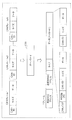
- FIG. 6 is a configuration diagram of the gateway 100.
- the gateway 100 includes a C communication unit 110a, a C communication unit 110b, an E communication unit 120, a transfer rule holding unit 130, and a transfer control unit 140.
- Each of these components is realized by a communication circuit, a memory, a digital circuit, a processor that executes a program stored in the memory, and the like in the gateway 100.
- the C communication unit 110a is a communication circuit or the like connected to the bus 30a configuring the first network, and includes a reception unit 111a that sequentially receives CAN frames from the bus 30a, and a transmission unit 112a that transmits CAN frames to the bus 30a. including.
- the C communication unit 110b is a communication circuit or the like connected to the bus 30b configuring the first network, and includes a reception unit 111b that sequentially receives CAN frames from the bus 30b, and a transmission unit 112b that transmits CAN frames to the bus 30b. including.
- the E communication unit 120 is a communication circuit or the like connected to the cable 20d (wired transmission path connected to the E-HUB 400) constituting the second network, and includes a reception unit 121 that receives an E frame from the cable 20d, 20d, and a transmission unit 122 that transmits the E frame.
- the transfer rule holding unit 130 is realized by a storage medium such as a memory, and holds reference information that defines frame transfer conditions and the like.
- the reference information includes, for example, transfer rule information in which a transfer target CAN-ID and a transfer source bus and a destination (MAC address, etc.) are associated, and a priority transfer target CAN-ID and a transfer source bus and a destination. The priority transfer list attached.
- the transfer control unit 140 is realized by, for example, a processor that executes a program, and determines whether or not the received frame should be transferred, and performs control related to transfer according to the determination result.
- the control related to the transfer is, for example, control for causing the E communication unit 120 to transmit an E frame including a plurality of pieces of CAN frame information as a payload to the cable 20d based on a plurality of CAN frames received sequentially.
- FIG. 7 shows an image in which an E frame is transmitted based on a plurality of CAN frames (CAN frames 1 to N) received by the gateway 100. As shown in the figure, the gateway 100 changes the configuration of the frame when transferring the frame.
- the payload of the E frame to be transmitted includes N CAN frame information, for example, which is a predetermined number.
- the data of the N CAN frame information is the contents (data) of the data field of the received N CAN frames.
- the contents of the CAN frame received and waiting to be transferred are stored in a storage medium (buffer) such as a memory provided in the gateway 100, for example.
- the E frame including N pieces of CAN frame information in FIG. 7 is received by the destination E-ECU (for example, E-ECU 200a) via the E-HUB 400, for example.
- the MAC address of the gateway 100 is set as the transmission source MAC address of the header of the E frame, and the ON CAN flag indicating that CAN frame information is included is set in the payload of the E frame.
- the MAC address of the destination E-ECU is set according to the transfer rule information held by the transfer rule holding unit 130 or the like.
- the transfer control unit 140 includes a determination unit 141 and a frame construction unit 142, and controls the transmission unit (the transmission unit 122, the transmission unit 112a, or the transmission unit 112b) under a certain condition according to the result of the determination by the determination unit 141. Then, the frame is transmitted.
- the determination unit 141 determines whether or not the CAN frame data should be transmitted to the second network based on the CAN-ID for the CAN frame received by the reception unit 111a or the reception unit 111b. This determination is performed, for example, according to predetermined reference information regarding CAN-ID. Further, the determination unit 141 selects the destination of the CAN frame data according to the reference information. The determination of whether or not the CAN frame should be transmitted to the second network and the selection of the destination of the frame (E frame or CAN frame) including the data of the CAN frame are, for example, 1 to which data should be transmitted to the second network. This is performed using transfer rule information indicating CAN-ID or the like of one or more CAN frames.
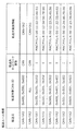
- the transfer rule information is information in which, for example, a transfer source, a transfer target CAN-ID, a transfer destination network type, and transfer destination identification information are associated with each other.
- E indicates the second network (E network)
- CAN indicates the first network.
- the E network is a second network in which transmission is performed using the Ethernet (registered trademark) protocol.
- the transfer destination identification information is information that identifies the MAC address if the transfer destination network type is E network, and identifies the bus if the transfer destination network type is CAN.
- the transfer destination network type is CAN and a plurality of connections are connected. This indicates that transmission is to be made to the CAN bus 2 among the CAN buses that are currently connected. In addition, all CAN frames received from the transfer source CAN bus 2 are to be transmitted to the CAN bus 1. Further, when transferring a CAN frame having a CAN-ID of 0x100, 0x101, or 0x102 received from the transfer source CAN bus 1, the CAN frame information is stored in the E frame because the transfer destination network type is the E network. This indicates that the destination MAC address of the E frame should be transmitted as 00: 11: 22: 33: 44: 55 (for example, the MAC address of the E-ECU 200a).
- the determination unit 141 distinguishes whether the bus that received the CAN frame is the CAN bus 1 (bus 30a) or the CAN bus 2 (bus 30b), compares it with the transfer rule information transfer source, and transfers the CAN-ID of the CAN frame. Match with the transfer target CAN-ID of the rule information. If there is a pair of the transfer source and transfer target CAN-ID corresponding to the collation, the determination unit 141 identifies the corresponding transfer destination network type and transfer destination identification information, and thereby determines a frame based on the received CAN frame. Select the destination. If there is no pair of transfer source and transfer target CAN-ID corresponding to the collation, the determination unit 141 should not transmit the received CAN frame to the first network, and also send it to the second network.
- the determination unit 141 determines that the received CAN frame should be transmitted to the second network. .
- the determination unit 141 uses any one of a plurality of MAC addresses as transfer destination identification information in the transfer rule information as CAN frame data or the like (CAN frame information) to be transmitted to the second network. It is selected as the destination of the included E frame.
- the reference information referred to by the determination unit 141 is, for example, a combination of a reception ID list indicating whether or not a CAN-ID to be transferred and transfer rule information in which a CAN-ID to be transferred and a transfer destination are associated with each other.
- any standard information format may be used.
- the reference information may be a list of CAN-IDs that should not be transferred, a function that distinguishes whether the CAN-IDs should be transferred, or the like.
- the destination in the reference information (for example, transfer destination identification information indicated by the transfer rule information) may be a MAC address or other E-ECU identification information (for example, an IP (Internet Protocol) address). Alternatively, it may be an address representing a subnetwork to which a plurality of E-ECUs of the same type are connected.
- the frame construction unit 142 When the determination unit 141 determines that a plurality of sequentially received CAN frames should be transmitted to the second network, the frame construction unit 142 has the same destination selected by the determination unit 141 (for example, the same destination E -Concatenate data (CAN frame information) between a plurality of (e.g., N, which is a predetermined number) CAN frames by connecting a plurality of CAN frames (CAN frame information), and the CAN flag is turned ON to construct an E frame ( (See FIG. 7). In this case, the frame construction unit 142 sets the MAC address of the destination E-ECU (the MAC address indicated by the transfer destination identification information in the transfer rule information) as the destination MAC address of the E frame header.
- the same destination E -Concatenate data CAN frame information
- N which is a predetermined number
- the transfer control unit 140 causes the transmission unit 122 of the E communication unit 120 to transmit the E frame constructed by the frame construction unit 142 to the cable 20d.
- the frame construction unit 142 provides an IP header in the payload of the E frame (for example, the IP header before the CAN flag in FIG. 7).
- the IP address of the E-ECU of the destination is included as the destination IP address in the IP header, and the MAC address searched based on the IP address of the destination E-ECU is used as the destination MAC of the E frame. It may be set as an address.
- the arrangement order of the CAN frame information when the frame construction unit 142 concatenates a plurality of pieces of CAN frame information and arranges them in the payload of the E frame may be any order.
- the following method is useful: .
- One method is that CAN frame information (data, etc.) relating to each of a plurality of CAN frames determined to be transmitted to the second network by the determination unit 141 is received by the reception unit 111a or the reception unit 111b.
- This is a method of arranging in the E frame in the order received.
- the E-ECU that has received the E frame transmitted to the gateway 100 via the E-HUB 400 can process the data included in the E frame based on the order in which the data is transmitted on the CAN bus. it can.
- CAN frame information (data, etc.) relating to each of a plurality of CAN frames determined to be transmitted to the second network by the determination unit 141 is based on the CAN-ID of the CAN frame.
- the frames are arranged in the E frame in an order according to a predetermined priority order for each CAN-ID.
- the predetermined priority order for each CAN-ID is, for example, in ascending order of CAN-ID values, as in the communication arbitration on the CAN bus.
- the E-ECU that has received the E frame transmitted to the gateway 100 via the E-HUB 400 performs processing based on the priority order (eg, importance order) of each data included in the E frame. Can be performed.
- the transfer control unit 140 receives the received CAN bus.
- the transmission unit (the transmission unit 112a or the transmission unit 112b) is controlled so that the frame is transmitted to the other CAN bus as it is.
- the transfer control unit 140 When the determination unit 141 selects an E-ECU (that is, the MAC address of the E-ECU) as a destination corresponding to a CAN frame received from any CAN bus, the transfer control unit 140 is identical.
- a predetermined condition relating to the received quantity of the CAN frame received by the receiving unit (receiving unit 111a or receiving unit 111b) is established for the CAN frame whose destination is selected, the frame building unit 142 is configured to construct an E frame.
- the transmitting unit 122 transmits the E frame.
- the predetermined condition relating to the received quantity is, for example, that N CAN frames corresponding to the same destination have been received (for example, the CAN frame information in the next E frame for the destination since the previous E frame was transmitted to the destination). Is received N times).
- the predetermined condition related to the received quantity is that a predetermined number M bytes of CAN frames whose CAN frame information should be included in the next E frame for the destination have been received since the previous E
- the transfer control unit 140 determines the specific even if the predetermined condition relating to the received quantity is not satisfied.
- the frame construction unit 142 constructs an E frame including CAN frame information (data etc.) of the CAN frame having the ID, and causes the transmission unit 122 to immediately transmit the E frame to the second network.
- the specific ID is, for example, a priority transfer target CAN-ID described in a priority transfer list as one piece of reference information held in the transfer rule holding unit 130.
- FIG. 9 shows an example of a priority transfer list as one piece of reference information used by the transfer control unit 140.
- the priority transfer list is information in which, for example, a transfer source, a priority transfer target CAN-ID, a transfer destination network type, and transfer destination identification information are associated with each other.
- the priority transfer list in the example of FIG. 9 includes, for example, a CAN frame having a CAN-ID of 0x100 received from the CAN bus 1 and an E-ECU (for example, E-ECU 200a) with a MAC address of 00: 11: 22: 33: 44: 55. ) To be transferred without delay.
- the transfer control unit 140 when the transfer control unit 140 receives a CAN frame with a CAN-ID of 0x100 from the CAN bus 1, the transfer control unit 140 immediately transmits an E frame in which CAN frame information such as data of the CAN frame is included in the payload.
- the transmission unit 122 transmits the data.
- the transfer control unit 140 distinguishes whether the bus that received the CAN frame is the CAN bus 1 (bus 30a) or the CAN bus 2 (bus 30b), and compares it with the transfer source of the priority transfer list.
- the CAN-ID is checked against the priority transfer target CAN-ID in the priority transfer list. Then, if there is a pair of the transfer source and transfer target CAN-ID corresponding to the collation, the transfer control unit 140 identifies the corresponding transfer destination identification information, thereby identifying the E frame based on the received CAN frame. Select a destination.
- the priority transfer target CAN-ID (that is, the specific ID) in the priority transfer list is, for example, a CAN-ID (error notification ID) predetermined for a CAN frame for notifying abnormality in vehicle travel control.
- a CAN-ID error notification ID
- the error notification information is displayed on the display of the IVI 300a connected to the E-ECU 200a. It is possible to quickly display a warning screen based on. Therefore, it is useful for preventing accidents.
- the CAN-ID of the CAN frame related to vehicle running control such as running, turning, and stopping can be determined as a specific ID.
- the transfer control unit 140 may determine the specific ID by any method other than the priority transfer list, for example, by setting all CAN-IDs having a value equal to or less than a predetermined threshold as the specific ID. Also good.
- the transfer control unit 140 transmits the E frame including the CAN frame information of the CAN frame having the specific ID to the transmission unit 122, it is determined by the determination unit 141 that it should be transmitted to the second network. Another E frame including CAN frame information (data, etc.) of one or a plurality of CAN frames not having a specific ID that has not been transmitted is generated in the frame construction unit 142, and the E frame is transmitted to the transmission unit 122. May be sent to. In addition, the transfer control unit 140 determines that the determination unit 141 should transmit the E frame including the CAN frame information of the CAN frame having the specific ID to the frame construction unit 142 and is still transmitted.
- CAN frame information of a CAN frame that does not have a specific ID construct an E frame, and cause the transmission unit 122 to transmit the E frame.
- the priority transfer target CAN-ID that is, the specific ID
- the transfer control unit 140 receives a CAN frame with a CAN-ID of 0x100.
- the accumulated CAN may be transmitted by being connected to the CAN frame information related to the frame and the CAN frame information related to the CAN frame of the specific ID (0x100).
- the transfer control unit 140 has a transmission control function that generates a CAN frame based on the content of the E frame received by the reception unit 121 of the E communication unit 120 and transmits the CAN frame to the transmission unit 112a or the transmission unit 112b to the CAN bus. You may have.
- the transmission unit 122 transmits, to the second network, an E frame including data of each of the plurality of CAN frames determined to be transmitted to the second network by the determination unit 141 under the control of the transfer control unit 140 ( That is, it is sent to the cable 20d). Specifically, the transmission unit 122 transmits an E frame including CAN frame information of each of a plurality of CAN frames for which the same destination is selected by the determination unit 141 to the destination, and the CAN frame information is included in the E frame. This is performed when a predetermined condition relating to the received quantity for the received CAN included is satisfied. Even when the predetermined condition is not satisfied, when the CAN frame having the specific ID is received, the transmission unit 122 transmits an E frame including CAN frame information related to the CAN frame.
- the transmitting unit 122 determines that the determining unit 141 should transmit to the second network and has not yet transmitted.
- the CAN frame information of a CAN frame that does not have a specific ID is included in the E frame and transmitted, or included in another E frame and transmitted.
- FIGS. 10 and 11 show a specific example of a transfer processing sequence related to CAN frame transfer in the gateway 100.
- FIG. The transfer processing sequence in FIGS. 10 and 11 represents a transfer process in cooperation with the C communication unit 110 a, the transfer control unit 140, the C communication unit 110 b, and the E communication unit 120 of the gateway 100.
- the CAN frame transfer is transmission of the same CAN frame as the received CAN frame to the CAN bus, or transmission of an E frame including CAN frame information of one or more received CAN frames.
- the C communication unit 110a connected to the CAN bus 1 receives the CAN-ID from the CAN bus 1 at the receiving unit 111a, and determines whether or not the CAN-ID is to be received (step S1). This determination is made with reference to, for example, a reception ID list in which CAN-IDs to be received are listed in advance. Note that the determination process based on the received ID list by the reception unit 111a may be shared by the determination unit 141 of the transfer control unit 140. In this case, the determination unit 141 determines whether it is a CAN-ID to be received (or whether it is a CAN-ID to be transferred) based on the reception ID list or transfer rule information.
- the receiving unit 111a of the C communication unit 110a determines that the CAN-ID is to be received in step S1
- the receiving unit 111a receives the CAN frame (step S2) and notifies the transfer control unit 140 of the CAN frame (step S3). ).
- the transfer control unit 140 acquires and refers to the transfer rule information held by the transfer rule holding unit 130 in order to confirm the transfer destination of the notified CAN frame (step S4).
- the transfer control unit 140 determines whether or not the CAN-ID of the CAN frame is a CAN-ID to be transferred to the CAN bus 2 (step S5). Only when the CAN-ID is to be transferred, the CAN frame is notified to the C communication unit 110b (step S6).
- the C communication unit 110b notified of the CAN frame transmits the CAN frame to the CAN bus 2 by the transmission unit 112b (step S7).
- step S5 If it is determined in step S5 that the CAN-ID of the CAN frame is not a CAN-ID to be transferred to the CAN bus 2, and if the CAN frame is notified in step S6, the transfer control unit 140 transfers Based on the rule information, it is determined whether or not the CAN-ID of the CAN frame is a CAN-ID to be transferred to the second network (E network) (step S8). If it is determined in step S8 that the CAN-ID is not to be transferred to the E network, the gateway 100 ends the transfer process.
- E network the second network
- step S8 If the transfer control unit 140 determines in step S8 that the CAN-ID of the CAN frame (CAN frame received in step S2) is the CAN-ID to be transferred to the E network, the transfer frame is The priority transfer list held by the transfer rule holding unit 130 is acquired and referred to in order to confirm whether or not it should be transferred preferentially (rapidly) (step S9). Then, the transfer control unit 140 determines whether or not the CAN-ID of the CAN frame is a CAN-ID (priority transfer target CAN-ID) described in the priority transfer list (step S10).
- CAN-ID priority transfer target CAN-ID
- the transfer control unit 140 When it is determined in step S10 that the CAN-ID of the CAN frame is the priority transfer target CAN-ID, the transfer control unit 140 includes the CAN frame information related to the CAN frame and the ON CAN flag in the payload.
- An E frame is generated (step S11).
- the MAC address (MAC address of the destination E-ECU) indicated by the corresponding transfer destination identification information in the priority transfer list is set.
- the MAC address of the gateway 100 is set as the source MAC address of the header of the E frame.
- the transfer control unit 140 gives priority notification (immediate notification) to the E communication unit 120 so that the E frame generated in step S11 is transmitted to the destination (step S12).
- the transmission unit 122 of the E communication unit 120 transmits the E frame (step S13).
- step S10 If it is determined in step S10 that the CAN-ID of the CAN frame is not the priority transfer target CAN-ID, the transfer control unit 140 displays the CAN frame information including the CAN-ID, size, and data of the CAN frame. In association with the destination (MAC address) selected based on the transfer rule information, it is stored in a buffer (a storage medium provided in the gateway 100) (step S14).
- a buffer a storage medium provided in the gateway 100
- step S12 or step S14 the transfer control unit 140 determines whether or not a predetermined condition relating to the received quantity of CAN frames is satisfied, that is, whether or not N pieces of CAN frame information having the same destination are stored in the buffer. Determination is made (step S15).
- step S15 When it is determined in step S15 that the predetermined condition is satisfied (that is, N pieces of CAN frame information of the same destination are accumulated), the transfer control unit 140 sets the N number of the same destination and the CAN flag set to ON.
- An E frame in which the CAN frame information is included in the payload is generated (step S16).
- the MAC address of the destination based on the transfer rule information is set as the destination MAC address of the header of the E frame, and the MAC address of the gateway 100 is set as the source address of the header, for example.
- the transfer control unit 140 notifies the E communication unit 120 to transmit the E frame generated in step S16 to the destination (step S17). Upon receiving this notification, the transmission unit 122 of the E communication unit 120 transmits the E frame (step S18).
- step S15 when the transfer control unit 140 determines that the predetermined condition is not satisfied, the gateway 100 ends the transfer process and waits for reception of the next CAN frame.
- the gateway 100 when the gateway 100 receives the CAN frame transmitted from the C-ECU to the CAN bus in the in-vehicle network including the first network and the second network having different communication protocols.
- the frame is transferred by transmitting information (CAN frame information) such as data of the CAN frame with the E-ECU as a destination under a certain condition.
- the gateway 100 includes CAN frame information related to a plurality of received CAN frames destined for the same E-ECU, and transmits an E frame including the ON CAN flag to the E-ECU. . Thereby, the transmission efficiency can be increased.
- the gateway 100 when receiving a CAN frame having a specific ID, the gateway 100 immediately transmits an E frame including CAN frame information related to the CAN frame to the specific E-ECU, thereby transferring the frame.
- the contents of the CAN frame or the like having the specific ID can be quickly transmitted to the E-ECU. That is, the in-vehicle network system 10 uses a transfer method that can cause delay in the transmission of frame information in order to increase the transmission efficiency of information. For example, by defining the CAN-ID of an important CAN frame as a specific ID, for example. Important information is quickly transmitted from the C-ECU to the E-ECU.
- the in-vehicle network system according to the present embodiment includes a gateway 100a having the same configuration as the gateway 100 (see FIG. 6) in the in-vehicle network system 10 shown in the first embodiment.
- the function of the transfer control unit 140 in the gateway 100a is partially different from the function of the transfer control unit 140 in the gateway 100.
- the same components as those shown in the first embodiment are denoted by the same reference numerals as those in the first embodiment, and the description thereof is omitted as appropriate.
- the in-vehicle network system according to the present embodiment is the same as the in-vehicle network system 10 shown in the first embodiment with respect to points that are not particularly described here.
- the transfer control unit 140 of the gateway 100 shown in the first embodiment determines that a plurality of CAN frames received sequentially should be transmitted to the second network
- the transfer control unit 140 is based on reference information (transfer rule information or the like).
- An E frame in which CAN frame information of a plurality of (for example, a predetermined number N) CAN frames is concatenated and included in the payload with the same selected destination (for example, the MAC address of the same E-ECU with the same destination) Is constructed (see FIG. 7).
- the transfer control unit 140 of the gateway 100a is selected based on reference information (transfer rule information, etc.) when it is determined that a plurality of CAN frames received sequentially should be transmitted to the second network.
- the E frame included in the payload is constructed by concatenating the CAN frame information of a plurality of (for example, a predetermined number N) CAN frames, and the E frame is transmitted to the transmission unit 122. 2 Send to network.
- the configuration of the E frame in this case is as shown in FIG. 12, for example.
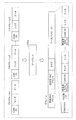
- FIG. 12 shows an image in which an E frame is transmitted based on a plurality of CAN frames (CAN frames 1 to N) received by the gateway 100a.
- N CAN frame information (CAN-ID, size and data), which is a predetermined number, is added to a transfer destination MAC address (that is, the destination E-ECU). MAC addresses) are added.
- the data of the N CAN frame information is the contents (data) of the data field of the received N CAN frames.
- the broadcast address is set as the destination MAC address of the header of the E frame
- the MAC address of the gateway 100 is set as the source MAC address of the header of the E frame
- the CAN frame information is included in the payload of the E frame.
- a CAN flag that is turned on is set.
- each E-ECU (E-ECU 200a to 200c, etc.) receives an E frame including N CAN frame information each having a transfer destination MAC address added thereto via, for example, E-HUB 400. Will be.
- the E-HUB 400 receives an E frame whose destination MAC address is a broadcast address
- the E-HUB 400 transmits the E frame from all ports other than the received port (that is, the connection terminal of the cable).
- Each E-ECU can extract CAN frame information addressed to its own device in the E frame by collating the transfer destination MAC address in the payload of the E frame with its own MAC address.
- the E-HUB 400 that has received an E frame including CAN frame information corresponding to each of a plurality of destinations as shown in FIG. 12 sets each of the plurality of CAN frame information in the payload of the E frame as a destination (transfer destination MAC address). For each destination, from the port toward the E-ECU indicated by the destination, the CAN frame information corresponding to the destination is included in the payload, and the transfer destination MAC address is set in the destination MAC address of the header You may have the division transfer function which sends out an E frame.
- An E-HUB having such a division transfer function determines whether to execute a division transfer function or a general E frame transfer function depending on, for example, whether or not the CAN flag in the payload of the E frame is ON.
- the gateway 100a uses not a broadcast address as a destination MAC address of the header of the E frame when transmitting the E frame. It is useful to set the MAC address of the E-HUB.
- the gateway 100a In addition, when the destination indicated by the transfer destination identification information in the transfer rule information (see FIG. 8) is an address representing a subnetwork to which a plurality of the same type of E-ECUs are connected, the gateway 100a In the configuration shown in FIG. 12, an E frame including a plurality of pieces of CAN frame information destined for the same type of E-ECU may be constructed and transmitted to the second network.
- the gateway 100a transmits an E frame including CAN frame information related to a plurality of CAN frames regardless of the destination based on the CAN frame received from the bus of the first network to the second network. Send to. Thereby, the transmission efficiency can be increased to some extent.
- Embodiments 1 and 2 have been described as examples of the technology according to the present disclosure.
- the technology according to the present disclosure is not limited to this, and can also be applied to embodiments in which changes, replacements, additions, omissions, and the like are appropriately performed.
- the following modifications are also included in one embodiment of the present disclosure.
- the in-vehicle network system shown in the above embodiment includes an E-HUB that includes a division transfer function and is connected to the second network in addition to the E-HUB 400 that does not have a division transfer function. May be.
- the gateway 100a shown in the second embodiment sequentially receives the CAN frame and transmits an E frame as shown in FIG. 12 to the E-HUB 400, and the E-HUB 400 performs the division transfer function on the E frame.
- the included E-HUB is transferred as the destination, the E-HUB including the division transfer function is used to divide a plurality of CAN frame information in the E frame, and the CAN frame information corresponding to the destination is obtained for each E-ECU for each destination. It is good also as transmitting the E frame containing.
- the in-vehicle network system is shown.
- the devices such as the gateway, ECU (E-ECU and C-ECU), E-HUB, and the like described above are various network communications such as robots and industrial equipment. Can be used in the system.
- the in-vehicle network includes the first network and the second network, and the first network transmits a CAN frame (data frame) through the CAN bus according to the CAN protocol.
- a CAN frame data frame
- an E frame (Ethernet (registered trademark) frame) is transmitted according to the Ethernet (registered trademark) protocol.
- This CAN protocol has a broad meaning including CANNOpen used for embedded systems in automation systems, or derivative protocols such as TTCAN (Time-Triggered CAN), CANFD (CAN-Flexible Data-Rate). It may be treated.
- the data frame in the CAN protocol may be an extended ID format in addition to the standard ID format.
- the Ethernet (registered trademark) frame may be, for example, an Ethernet (registered trademark) version 2 frame, or may be a frame defined by IEEE 802.3.
- the Ethernet (registered trademark) protocol includes Ethernet (registered trademark) AVB (Audio Video Bridging) according to IEEE 802.1 or Ethernet (registered trademark) TSN (Time Sensitive Network) and Ethernet (registered trademark) according to IEEE 802.1. ) / IP (Industrial Protocol), EtherCAT (registered trademark) (Ethernet (registered trademark) for Control Automation Technology), etc.
- the first network transmits a first type frame (for example, a CAN frame) by a bus according to a first communication protocol, and the second network follows a second communication protocol different from the first communication protocol.
- the first communication protocol is, for example, the CAN protocol, but is not limited to the CAN protocol, for example, LIN (Local Interconnect Network), MOST (registered trademark) (Media Oriented Systems Transport), FlexRay (registered trademark), or the like.
- the second communication protocol is, for example, the Ethernet (registered trademark) protocol, but is not limited to the Ethernet (registered trademark) protocol, and may be, for example, a broader reach protocol.
- the information transmitted by the first type electronic control unit (for example, C-ECU) connected to the first network by the in-vehicle network including the first network and the second network is transmitted to the second type connected to the second network. It can be transmitted to an electronic control unit (eg, E-ECU).
- E-ECU electronice control unit
- Ethernet registered trademark
- the second communication protocol may be various protocols having a higher communication speed than the first communication protocol.
- the second type frame (for example, E frame) includes the data of the first type frame (for example, CAN frame) to be transmitted to the second network in the payload of the second type frame (for example, for example, although it has an identification flag (for example, a CAN flag) for determining whether or not it includes (CAN frame information), the identification flag may be included in the header of the second type frame.
- the gateway 100 may include the CAN flag in the header of the E frame. Thereby, it is possible to determine whether or not the payload includes CAN frame information only by referring to the header of the E frame. For example, when the payload of the E frame is encrypted, the processing is simplified (decrypted). May be possible.
- a bit identifying whether or not the destination MAC address in the header of the E frame is a global MAC address may be used as a CAN flag (for example, a value indicating a local MAC address is treated as a CAN flag being ON).
- a CAN flag may be provided in the type field in the header of the E frame.
- the gateway 100 may include the CAN flag in both the header and the payload of the E frame.
- the gateway 100 is connected to one Ethernet (registered trademark) cable 20d in relation to the second network.
- the gateway 100 is connected to a plurality of Ethernet (registered trademark) cables.
- Each port may be provided. That is, the gateway 100 may be integrated with the E-HUB 400.
- the gateway 100 selects a CAN frame destination based on reference information such as transfer rule information, specifies a port connected to a cable corresponding to the destination by, for example, a MAC address table, and sets E to the port.
- a frame may be transmitted.
- the determination unit 141 in the transfer control unit 140 of the gateway 100 refers to reference information (for example, transfer rule information and a MAC address table) that associates each of a plurality of cables with a CAN-ID. Based on the CAN-ID of the CAN frame received by the receiving unit 111a or the receiving unit 111b, CAN frame information that is data of the CAN frame to be transmitted to the second network through one of the cables As the destination of the message. Then, the transfer control unit 140 includes a frame construction unit 142 including CAN frame information, which is data of each of a plurality of CAN frames where the determination unit 141 has the same cable selected as the CAN frame information transmission destination.
- reference information for example, transfer rule information and a MAC address table
- the gateway 100 may select a plurality of cables and send an E frame having the same payload including one or more pieces of CAN frame information to the plurality of cables.
- the gateway 100 may not have a function as a switch (switching hub), and the E frame may be transmitted to all the cables without distinguishing the destination MAC address of the E frame.
- the gateway 100 when a predetermined condition relating to the reception quantity of CAN frames received sequentially is satisfied (for example, when CAN frame information of the same destination is accumulated in N buffers), An E frame including CAN frame information related to these CAN frames is transmitted to the second network.
- a predetermined condition relating to time may be used. That is, when the gateway 100 measures the time and a predetermined condition relating to time is satisfied, an E frame including unsent CAN frame information of the same destination accumulated in the buffer is generated and transmitted.
- the unit 122 may transmit the E frame to the second network.
- the predetermined condition relating to time is, for example, a condition that is satisfied when a predetermined time has elapsed since the previous E frame was transmitted.
- the gateway 100 is connected to a plurality of CAN buses in relation to the first network, but may be connected to a single CAN bus.
- the transfer source information may be omitted in the transfer rule information and the priority transfer list.
- the CAN frame information included in the E frame transmitted by the gateway 100 is composed of CAN-ID, size, and data.
- the CAN frame information includes only data. It may be included.
- the order of execution of the various processing procedures shown in the above-described embodiment is not necessarily limited to the order described above.
- the execution order can be changed, a plurality of procedures can be performed in parallel, or a part of the procedures can be omitted without departing from the gist.
- the gateway, ECU, E-HUB, and other devices in the above embodiments may include other hardware components such as a hard disk device, a display, a keyboard, and a mouse.
- the program stored in the memory may be executed by a processor to realize the function of the apparatus in software, or the function may be realized by dedicated hardware (digital circuit or the like). May be.
- the function sharing of each component in the apparatus can be changed.
- a part or all of the components constituting each device in the above embodiment may be configured by one system LSI (Large Scale Integration).
- the system LSI is an ultra-multifunctional LSI manufactured by integrating a plurality of components on a single chip.
- the system LSI is a computer system including a microprocessor, a ROM, a RAM, and the like. .
- a computer program is recorded in the RAM.
- the system LSI achieves its functions by the microprocessor operating according to the computer program.
- each part of the constituent elements constituting each of the above devices may be individually made into one chip, or may be made into one chip so as to include a part or the whole.
- the system LSI is used here, it may be called IC, LSI, super LSI, or ultra LSI depending on the degree of integration.
- the method of circuit integration is not limited to LSI's, and implementation using dedicated circuitry or general purpose processors is also possible.
- An FPGA Field Programmable Gate Array
- a reconfigurable processor that can reconfigure the connection and setting of circuit cells inside the LSI may be used.
- integrated circuit technology comes out to replace LSI's as a result of the advancement of semiconductor technology or a derivative other technology, it is naturally also possible to carry out function block integration using this technology. Biotechnology can be applied as a possibility.
- a part or all of the constituent elements constituting each of the above devices may be constituted by an IC card or a single module that can be attached to and detached from each device.
- the IC card or the module is a computer system including a microprocessor, a ROM, a RAM, and the like.
- the IC card or the module may include the super multifunctional LSI described above.
- the IC card or the module achieves its function by the microprocessor operating according to the computer program. This IC card or this module may have tamper resistance.
- a transfer method including all or part of the processing procedure illustrated in FIGS.
- transmission of the second type frame is performed according to the second communication protocol different from the first communication protocol and the bus of the first network where the first type frame is transmitted via the bus according to the first communication protocol.
- a transfer method used in a gateway connected to the second network the reception step of sequentially receiving the first type frame from the bus (for example, step S2), and the first type frame received in the reception step
- a determination step for example, step S8 for determining whether data of the first type frame should be transmitted to the second network, and a plurality of first types determined to be transmitted to the second network in the determination step
- a transmission step of transmitting a second type frame including data of each frame to the second network for example, Step a S16 ⁇ S18
- it may be a program (computer program) for realizing this method by a computer, or may be a digital signal composed of the computer program.
- the program may be a program for executing a predetermined transfer process including a reception step, a determination step, and a transmission step according to the transfer method.
- a computer-readable recording medium such as a flexible disk, a hard disk, a CD-ROM, an MO, a DVD, a DVD-ROM, a DVD-RAM, or a BD can be used as the computer program or the digital signal. (Blu-ray (registered trademark) Disc), recorded on a semiconductor memory or the like. Further, the digital signal may be recorded on these recording media.
- the computer program or the digital signal may be transmitted via an electric communication line, a wireless or wired communication line, a network typified by the Internet, data broadcasting, or the like.
- an aspect of the present disclosure may be a computer system including a microprocessor and a memory, the memory recording the computer program, and the microprocessor operating according to the computer program.
- the program or the digital signal may be carried out by recording and transferring the program or the digital signal on the recording medium, or by transferring the program or the digital signal via the network or the like, by another independent computer system It may be carried out.
- the present disclosure can be used to transmit information transmitted from an ECU connected to a bus of a first network such as CAN to another ECU via a second network such as Ethernet (registered trademark).
- a first network such as CAN
- a second network such as Ethernet (registered trademark).
Landscapes
- Engineering & Computer Science (AREA)
- Computer Networks & Wireless Communication (AREA)
- Signal Processing (AREA)
- Health & Medical Sciences (AREA)
- Computing Systems (AREA)
- General Health & Medical Sciences (AREA)
- Medical Informatics (AREA)
- Small-Scale Networks (AREA)
Priority Applications (6)
| Application Number | Priority Date | Filing Date | Title |
|---|---|---|---|
| EP20185748.9A EP3745657B1 (de) | 2016-05-27 | 2017-04-20 | Gateway-vorrichtung, fahrzeugnetzwerksystem, übertragungsverfahren und programm |
| CN201780004577.1A CN108370342B (zh) | 2016-05-27 | 2017-04-20 | 网关装置、车载网络系统、转送方法和程序 |
| CN202110652898.0A CN113395197B (zh) | 2016-05-27 | 2017-04-20 | 网关装置、车载网络系统、转送方法和计算机可读记录介质 |
| EP17802500.3A EP3468106B1 (de) | 2016-05-27 | 2017-04-20 | Gateway-vorrichtung, fahrzeuginternes netzwerksystem, übertragungsverfahren und programm |
| US16/169,039 US10756930B2 (en) | 2016-05-27 | 2018-10-24 | Gateway device, vehicle network system, transfer method, and non-transitory computer-readable recording medium storing program |
| US16/929,918 US11368338B2 (en) | 2016-05-27 | 2020-07-15 | Multi-protocol vehicle relay communication method, gateway device, vehicle network system, transfer method, and non-transitory computer-readable recording medium storing program |
Applications Claiming Priority (4)
| Application Number | Priority Date | Filing Date | Title |
|---|---|---|---|
| US201662342551P | 2016-05-27 | 2016-05-27 | |
| US62/342551 | 2016-05-27 | ||
| JP2017-046311 | 2017-03-10 | ||
| JP2017046311A JP6879789B2 (ja) | 2016-05-27 | 2017-03-10 | ゲートウェイ装置、車載ネットワークシステム、転送方法及びプログラム |
Related Child Applications (1)
| Application Number | Title | Priority Date | Filing Date |
|---|---|---|---|
| US16/169,039 Continuation US10756930B2 (en) | 2016-05-27 | 2018-10-24 | Gateway device, vehicle network system, transfer method, and non-transitory computer-readable recording medium storing program |
Publications (1)
| Publication Number | Publication Date |
|---|---|
| WO2017203902A1 true WO2017203902A1 (ja) | 2017-11-30 |
Family
ID=60412796
Family Applications (1)
| Application Number | Title | Priority Date | Filing Date |
|---|---|---|---|
| PCT/JP2017/015814 Ceased WO2017203902A1 (ja) | 2016-05-27 | 2017-04-20 | ゲートウェイ装置、車載ネットワークシステム、転送方法及びプログラム |
Country Status (3)
| Country | Link |
|---|---|
| EP (1) | EP3745657B1 (de) |
| CN (1) | CN113395197B (de) |
| WO (1) | WO2017203902A1 (de) |
Cited By (8)
| Publication number | Priority date | Publication date | Assignee | Title |
|---|---|---|---|---|
| CN110048922A (zh) * | 2017-12-28 | 2019-07-23 | 丰田自动车株式会社 | 车载系统、网关、中继器、介质、方法、系统及车辆 |
| CN111600765A (zh) * | 2020-06-10 | 2020-08-28 | 北京经纬恒润科技有限公司 | 通信故障记录方法及网关控制器 |
| CN111953585A (zh) * | 2019-05-14 | 2020-11-17 | 现代自动车株式会社 | 网关装置及其控制方法 |
| CN113542277A (zh) * | 2021-07-16 | 2021-10-22 | 上海海得控制系统股份有限公司 | Canopen设备通过tsn网络桥接的方法、系统、介质及装置 |
| WO2022085057A1 (ja) | 2020-10-19 | 2022-04-28 | 日産自動車株式会社 | 中継装置、通信ネットワークシステム及び通信制御方法 |
| WO2022085055A1 (ja) | 2020-10-19 | 2022-04-28 | 日産自動車株式会社 | 中継装置、通信ネットワークシステム及び通信制御方法 |
| DE102018215706B4 (de) | 2017-09-15 | 2024-12-19 | Yazaki Corporation | Fahrzeug-Netzwerk-Vorrichtung |
| WO2025052571A1 (ja) | 2023-09-06 | 2025-03-13 | 日産自動車株式会社 | 通信システム |
Families Citing this family (1)
| Publication number | Priority date | Publication date | Assignee | Title |
|---|---|---|---|---|
| US11464079B1 (en) * | 2021-01-22 | 2022-10-04 | Samsara Inc. | Automatic coupling of a gateway device and a vehicle |
Citations (2)
| Publication number | Priority date | Publication date | Assignee | Title |
|---|---|---|---|---|
| US20140126584A1 (en) * | 2012-11-06 | 2014-05-08 | Electronics And Telecommunications Research Institute | Frame conversion apparatus for converting controller area network frame into ethernet frame and frame conversion method thereof |
| JP2015139093A (ja) * | 2014-01-22 | 2015-07-30 | 株式会社デンソー | 中継装置 |
Family Cites Families (10)
| Publication number | Priority date | Publication date | Assignee | Title |
|---|---|---|---|---|
| JPH10145431A (ja) * | 1996-11-12 | 1998-05-29 | Chokosoku Network Computer Gijutsu Kenkyusho:Kk | フレーム変換方式 |
| US8554896B2 (en) * | 2000-03-02 | 2013-10-08 | Dearborn Group, Inc. | Protocol adapter for transferring diagnostic signals between in-vehicle networks and a computer |
| JP2007166302A (ja) * | 2005-12-14 | 2007-06-28 | Denso Corp | 車載ネットワーク中継装置 |
| CN101271337B (zh) * | 2008-04-03 | 2011-07-06 | 江苏大学 | 基于CAN总线网关的pH值测控装置及测控方法 |
| JP5434512B2 (ja) * | 2009-11-18 | 2014-03-05 | トヨタ自動車株式会社 | 車載通信システム、ゲートウェイ装置 |
| DE102012215765A1 (de) * | 2012-09-05 | 2014-05-15 | Robert Bosch Gmbh | Gateway-Modul für ein Kommunikationssystem, Kommunikationssystem und Verfahren zur Übertragung von Daten zwischen Teilnehmern eines Kommunikationssystems |
| JP5919205B2 (ja) * | 2013-01-28 | 2016-05-18 | 日立オートモティブシステムズ株式会社 | ネットワーク装置およびデータ送受信システム |
| KR101500094B1 (ko) * | 2013-07-01 | 2015-03-06 | 현대자동차주식회사 | 이더넷 기반의 차량 네트워크 메시지 전달 시스템 및 방법 |
| WO2015159320A1 (ja) * | 2014-04-16 | 2015-10-22 | 三菱電機株式会社 | プロトコル変換装置、及び産業ネットワークシステム |
| JP2016111477A (ja) | 2014-12-04 | 2016-06-20 | トヨタ自動車株式会社 | 通信システム、及びゲートウェイ |
-
2017
- 2017-04-20 EP EP20185748.9A patent/EP3745657B1/de active Active
- 2017-04-20 CN CN202110652898.0A patent/CN113395197B/zh active Active
- 2017-04-20 WO PCT/JP2017/015814 patent/WO2017203902A1/ja not_active Ceased
Patent Citations (2)
| Publication number | Priority date | Publication date | Assignee | Title |
|---|---|---|---|---|
| US20140126584A1 (en) * | 2012-11-06 | 2014-05-08 | Electronics And Telecommunications Research Institute | Frame conversion apparatus for converting controller area network frame into ethernet frame and frame conversion method thereof |
| JP2015139093A (ja) * | 2014-01-22 | 2015-07-30 | 株式会社デンソー | 中継装置 |
Non-Patent Citations (2)
| Title |
|---|
| JUN MATSUMURA ET AL.: "Shasai Network ni Okeru CAN-Ethernet Protocol Henkan Algorithm [CAN-Ethernet protocol convert algorithm for automotive networks]", IPSJ SIG NOTES 2012 (HEISEI 24) NENDO KUMIKOMI SYSTEM (EMB), no. 7, 13 March 2013 (2013-03-13), pages 1 - 6, XP009510270 * |
| MITSUHIRO KITANI ET AL.: "Development of Data Communication Method In-vehicle Network for Automated Driving", IPSJ SIG NOTES, GROUPWARE AND NETWORK SERVICES (GN), 21 January 2016 (2016-01-21), XP055441760 * |
Cited By (13)
| Publication number | Priority date | Publication date | Assignee | Title |
|---|---|---|---|---|
| DE102018215706B4 (de) | 2017-09-15 | 2024-12-19 | Yazaki Corporation | Fahrzeug-Netzwerk-Vorrichtung |
| CN110048922B (zh) * | 2017-12-28 | 2021-09-28 | 丰田自动车株式会社 | 车载系统、网关、中继器、介质、方法、系统及车辆 |
| CN110048922A (zh) * | 2017-12-28 | 2019-07-23 | 丰田自动车株式会社 | 车载系统、网关、中继器、介质、方法、系统及车辆 |
| CN111953585A (zh) * | 2019-05-14 | 2020-11-17 | 现代自动车株式会社 | 网关装置及其控制方法 |
| CN111953585B (zh) * | 2019-05-14 | 2024-01-23 | 现代自动车株式会社 | 网关装置及其控制方法 |
| CN111600765B (zh) * | 2020-06-10 | 2022-08-19 | 北京经纬恒润科技股份有限公司 | 通信故障记录方法及网关控制器 |
| CN111600765A (zh) * | 2020-06-10 | 2020-08-28 | 北京经纬恒润科技有限公司 | 通信故障记录方法及网关控制器 |
| WO2022085055A1 (ja) | 2020-10-19 | 2022-04-28 | 日産自動車株式会社 | 中継装置、通信ネットワークシステム及び通信制御方法 |
| WO2022085057A1 (ja) | 2020-10-19 | 2022-04-28 | 日産自動車株式会社 | 中継装置、通信ネットワークシステム及び通信制御方法 |
| US12101203B2 (en) | 2020-10-19 | 2024-09-24 | Nissan Motor Co., Ltd. | Relay device, communication network system, and communication control method |
| US12184446B2 (en) | 2020-10-19 | 2024-12-31 | Nissan Motor Co., Ltd. | Relay device, communication network system, and communication control method |
| CN113542277A (zh) * | 2021-07-16 | 2021-10-22 | 上海海得控制系统股份有限公司 | Canopen设备通过tsn网络桥接的方法、系统、介质及装置 |
| WO2025052571A1 (ja) | 2023-09-06 | 2025-03-13 | 日産自動車株式会社 | 通信システム |
Also Published As
| Publication number | Publication date |
|---|---|
| CN113395197A (zh) | 2021-09-14 |
| CN113395197B (zh) | 2022-07-26 |
| EP3745657A1 (de) | 2020-12-02 |
| EP3745657B1 (de) | 2022-03-09 |
Similar Documents
| Publication | Publication Date | Title |
|---|---|---|
| JP7312210B2 (ja) | ゲートウェイ装置、車載ネットワークシステム、転送方法及びプログラム | |
| JP7289332B2 (ja) | 電子制御ユニット、フレーム生成方法及びプログラム | |
| CN108370343B (zh) | 网络集线器、转送方法以及车载网络系统 | |
| JP7192074B2 (ja) | ネットワークハブ、転送方法及び車載ネットワークシステム | |
| CN113395197B (zh) | 网关装置、车载网络系统、转送方法和计算机可读记录介质 | |
| US10693675B2 (en) | Electronic control unit, communication method, and onboard network system | |
| JP2017212728A (ja) | ネットワークハブ、転送方法及び車載ネットワークシステム | |
| WO2017203903A1 (ja) | 電子制御ユニット、通信方法及び車載ネットワークシステム | |
| CN113553285B (zh) | 电子控制单元、帧生成方法和记录介质 | |
| WO2017203906A1 (ja) | ネットワークハブ、転送方法及び車載ネットワークシステム |
Legal Events
| Date | Code | Title | Description |
|---|---|---|---|
| NENP | Non-entry into the national phase |
Ref country code: DE |
|
| 121 | Ep: the epo has been informed by wipo that ep was designated in this application |
Ref document number: 17802500 Country of ref document: EP Kind code of ref document: A1 |
|
| ENP | Entry into the national phase |
Ref document number: 2017802500 Country of ref document: EP Effective date: 20190102 |