WO2017203923A1 - スクロール圧縮機 - Google Patents
スクロール圧縮機 Download PDFInfo
- Publication number
- WO2017203923A1 WO2017203923A1 PCT/JP2017/016399 JP2017016399W WO2017203923A1 WO 2017203923 A1 WO2017203923 A1 WO 2017203923A1 JP 2017016399 W JP2017016399 W JP 2017016399W WO 2017203923 A1 WO2017203923 A1 WO 2017203923A1
- Authority
- WO
- WIPO (PCT)
- Prior art keywords
- key
- gap
- axis
- scroll
- scroll compressor
- Prior art date
- Legal status (The legal status is an assumption and is not a legal conclusion. Google has not performed a legal analysis and makes no representation as to the accuracy of the status listed.)
- Ceased
Links
Images


Classifications
-
- F—MECHANICAL ENGINEERING; LIGHTING; HEATING; WEAPONS; BLASTING
- F04—POSITIVE - DISPLACEMENT MACHINES FOR LIQUIDS; PUMPS FOR LIQUIDS OR ELASTIC FLUIDS
- F04C—ROTARY-PISTON, OR OSCILLATING-PISTON, POSITIVE-DISPLACEMENT MACHINES FOR LIQUIDS; ROTARY-PISTON, OR OSCILLATING-PISTON, POSITIVE-DISPLACEMENT PUMPS
- F04C18/00—Rotary-piston pumps specially adapted for elastic fluids
- F04C18/02—Rotary-piston pumps specially adapted for elastic fluids of arcuate-engagement type, i.e. with circular translatory movement of co-operating members, each member having the same number of teeth or tooth-equivalents
- F04C18/0207—Rotary-piston pumps specially adapted for elastic fluids of arcuate-engagement type, i.e. with circular translatory movement of co-operating members, each member having the same number of teeth or tooth-equivalents both members having co-operating elements in spiral form
- F04C18/0215—Rotary-piston pumps specially adapted for elastic fluids of arcuate-engagement type, i.e. with circular translatory movement of co-operating members, each member having the same number of teeth or tooth-equivalents both members having co-operating elements in spiral form where only one member is moving
-
- F—MECHANICAL ENGINEERING; LIGHTING; HEATING; WEAPONS; BLASTING
- F01—MACHINES OR ENGINES IN GENERAL; ENGINE PLANTS IN GENERAL; STEAM ENGINES
- F01C—ROTARY-PISTON OR OSCILLATING-PISTON MACHINES OR ENGINES
- F01C17/00—Arrangements for drive of co-operating members, e.g. for rotary piston and casing
- F01C17/06—Arrangements for drive of co-operating members, e.g. for rotary piston and casing using cranks, universal joints or similar elements
- F01C17/066—Arrangements for drive of co-operating members, e.g. for rotary piston and casing using cranks, universal joints or similar elements with an intermediate piece sliding along perpendicular axes, e.g. Oldham coupling
-
- F—MECHANICAL ENGINEERING; LIGHTING; HEATING; WEAPONS; BLASTING
- F04—POSITIVE - DISPLACEMENT MACHINES FOR LIQUIDS; PUMPS FOR LIQUIDS OR ELASTIC FLUIDS
- F04C—ROTARY-PISTON, OR OSCILLATING-PISTON, POSITIVE-DISPLACEMENT MACHINES FOR LIQUIDS; ROTARY-PISTON, OR OSCILLATING-PISTON, POSITIVE-DISPLACEMENT PUMPS
- F04C23/00—Combinations of two or more pumps, each being of rotary-piston or oscillating-piston type, specially adapted for elastic fluids; Pumping installations specially adapted for elastic fluids; Multi-stage pumps specially adapted for elastic fluids
- F04C23/008—Hermetic pumps
-
- F—MECHANICAL ENGINEERING; LIGHTING; HEATING; WEAPONS; BLASTING
- F04—POSITIVE - DISPLACEMENT MACHINES FOR LIQUIDS; PUMPS FOR LIQUIDS OR ELASTIC FLUIDS
- F04C—ROTARY-PISTON, OR OSCILLATING-PISTON, POSITIVE-DISPLACEMENT MACHINES FOR LIQUIDS; ROTARY-PISTON, OR OSCILLATING-PISTON, POSITIVE-DISPLACEMENT PUMPS
- F04C29/00—Component parts, details or accessories of pumps or pumping installations, not provided for in groups F04C18/00 - F04C28/00
- F04C29/0042—Driving elements, brakes, couplings, transmissions specially adapted for pumps
- F04C29/005—Means for transmitting movement from the prime mover to driven parts of the pump, e.g. clutches, couplings, transmissions
- F04C29/0057—Means for transmitting movement from the prime mover to driven parts of the pump, e.g. clutches, couplings, transmissions for eccentric movement
-
- F—MECHANICAL ENGINEERING; LIGHTING; HEATING; WEAPONS; BLASTING
- F04—POSITIVE - DISPLACEMENT MACHINES FOR LIQUIDS; PUMPS FOR LIQUIDS OR ELASTIC FLUIDS
- F04C—ROTARY-PISTON, OR OSCILLATING-PISTON, POSITIVE-DISPLACEMENT MACHINES FOR LIQUIDS; ROTARY-PISTON, OR OSCILLATING-PISTON, POSITIVE-DISPLACEMENT PUMPS
- F04C29/00—Component parts, details or accessories of pumps or pumping installations, not provided for in groups F04C18/00 - F04C28/00
- F04C29/02—Lubrication; Lubricant separation
-
- F—MECHANICAL ENGINEERING; LIGHTING; HEATING; WEAPONS; BLASTING
- F04—POSITIVE - DISPLACEMENT MACHINES FOR LIQUIDS; PUMPS FOR LIQUIDS OR ELASTIC FLUIDS
- F04C—ROTARY-PISTON, OR OSCILLATING-PISTON, POSITIVE-DISPLACEMENT MACHINES FOR LIQUIDS; ROTARY-PISTON, OR OSCILLATING-PISTON, POSITIVE-DISPLACEMENT PUMPS
- F04C2270/00—Control; Monitoring or safety arrangements
- F04C2270/70—Safety, emergency conditions or requirements
- F04C2270/72—Safety, emergency conditions or requirements preventing reverse rotation
Definitions
- the present invention relates to a scroll compressor including an Oldham coupling for preventing the rotation of the movable scroll.
- a scroll compressor used in a refrigeration system or the like includes a fixed scroll and a movable scroll.
- Each of the fixed scroll and the movable scroll has a spiral portion.
- a compression chamber which is a space in which a fluid such as refrigerant gas is compressed, is formed.
- the scroll compressor revolves the movable scroll and changes the volume of the compression chamber to compress the fluid.
- the Oldham coupling is installed between the movable scroll and a fixed member such as a housing.
- the Oldham coupling includes an annular main body portion and a key portion protruding in the vertical direction from the main body portion. Each key part has a surface which slides with a movable scroll or a fixed member.
- Lubricating oil for preventing seizure of the sliding surface is supplied to the sliding portion between the Oldham joint and the movable scroll and the sliding portion between the Oldham joint and the fixed member. If the lubricating oil is not sufficiently supplied to the sliding portion, the sliding surface may become hot and seizure may occur.
- An object of the present invention is to provide a scroll compressor having high reliability by suppressing seizure of the sliding surface of the Oldham joint and the movable scroll.
- the scroll compressor according to the first aspect of the present invention includes a movable scroll, a stationary member, and an Oldham coupling.
- the movable scroll has a first keyway.
- the stationary member has a second keyway.
- the Oldham coupling is provided between the movable scroll and the stationary member.
- the Oldham coupling is movable relative to the stationary member along the first axis, and is movable relative to the movable scroll along the second axis.
- the Oldham coupling includes an annular main body portion, two pairs of first key portions, and a second key portion.
- the annular main body has a first horizontal plane and a second horizontal plane that face each other. The first key portion protrudes from the first horizontal plane and is fitted into the first key groove.
- the first key portion is slidable with the movable scroll along the second axis.
- the second key portion protrudes from the second horizontal plane and is fitted into the second key groove.
- the second key portion is slidable with the stationary member along the first axis.
- a key gap is formed between the outer peripheral surface of the first key portion and the inner peripheral surface of the first key groove.
- the key gap has a first gap and a second gap.
- the first gap is formed along the second axis on the gravity center side of the Oldham joint.
- the second gap is formed along the second axis on the side opposite to the center of gravity of the Oldham joint.
- the second gap is wider than the first gap.
- the first key portion of the Oldham joint has a sliding surface that is a radially inner side surface of the Oldham joint and a guide surface that is a radially outer side surface.
- the sliding surface of the first key portion is a surface that slides with the movable scroll, and forms a first gap between the inner surface of the first key groove of the movable scroll.
- a second clearance is formed between the guide surface of the first key portion and the inner peripheral surface of the first key groove of the movable scroll. Since the second gap is wider than the first gap, the lubricating oil supplied to the first key groove is easier to hold than the first gap.
- this scroll compressor has high reliability by suppressing seizure of the sliding surfaces of the Oldham coupling and the movable scroll.
- the scroll compressor according to the second aspect of the present invention is the scroll compressor according to the first aspect, and the first gap is 15 ⁇ m to 50 ⁇ m.
- the first gap between the sliding surface of the first key portion and the inner peripheral surface of the first key groove sufficiently suppresses rattling of the sliding Oldham joint. It is so narrow that it is large enough to retain an amount of lubricating oil that can sufficiently suppress seizure of the sliding surface. Therefore, the occurrence of seizure of the sliding surface due to insufficient supply of lubricating oil to the first gap is suppressed.
- the scroll compressor according to the third aspect of the present invention is the scroll compressor according to the first aspect or the second aspect, and the second gap is 200 ⁇ m to 1000 ⁇ m.
- the second gap between the guide surface of the first key portion and the inner peripheral surface of the first key groove can hold a larger amount of lubricating oil than the first gap.
- a part of the lubricating oil held in the second gap is supplied to the first gap through the gap between the outer peripheral surface of the first key portion and the inner peripheral surface of the first key groove. . Therefore, the occurrence of seizure of the sliding surface due to insufficient supply of lubricating oil to the first gap is suppressed.
- the scroll compressor which concerns on the 4th viewpoint of this invention is a scroll compressor which concerns on any one of the 1st thru
- the scroll compressor according to the fifth aspect of the present invention is the scroll compressor according to the fourth aspect, and the Oldham coupling has a pair of second key portions.
- the second key portion is provided on the first shaft across the second shaft.
- a scroll compressor includes a movable scroll, a stationary member, and an Oldham joint.
- the movable scroll has a first keyway.
- the stationary member has a second keyway.
- the Oldham coupling is provided between the movable scroll and the stationary member.
- the Oldham coupling is movable relative to the stationary member along the first axis, and is movable relative to the movable scroll along the second axis.
- the Oldham coupling includes an annular main body portion, at least two first key portions, and a second key portion.
- the annular main body has a first horizontal plane and a second horizontal plane that face each other. The first key portion protrudes from the first horizontal plane and is fitted into the first key groove.
- the first key portion is slidable with the movable scroll along the second axis.
- the second key portion protrudes from the second horizontal plane and is fitted into the second key groove.
- the second key portion is slidable with the stationary member along the first axis.
- a key gap is formed between the outer peripheral surface of the first key portion and the inner peripheral surface of the first key groove.
- the key gap has a first gap and a second gap.
- the first gap is formed along the second axis on the gravity center side of the Oldham joint.
- the second gap is formed along the second axis on the side opposite to the center of gravity of the Oldham joint.
- the second gap is wider than the first gap.
- the scroll compressor according to the present invention has high reliability by suppressing seizure of the sliding surface of the Oldham joint and the movable scroll.
- FIG. 6 is a cross-sectional view taken along line VI-VI in FIG. 5.
- FIG. 10 is a sectional view taken along line XX in FIG. 9.
- a scroll compressor 101 according to an embodiment of the present invention will be described with reference to the drawings.
- the scroll compressor 101 is used in a refrigeration apparatus such as an air conditioner.
- the scroll compressor 101 compresses the refrigerant gas circulating in the refrigerant circuit of the refrigeration apparatus.
- the scroll compressor 101 is a high and low pressure dome type scroll compressor.
- the scroll compressor 101 compresses the refrigerant using two scroll members having spiral wraps that mesh with each other.
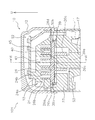
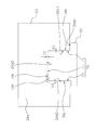
- FIG. 1 is a longitudinal sectional view of the scroll compressor 101.
- the scroll compressor 101 mainly includes a casing 10, a compression mechanism 15, a housing 23, an Oldham joint 39, a drive motor 16, a lower bearing 60, a crankshaft 17, a suction pipe 19, and a discharge pipe 20. Consists of Next, each component of the scroll compressor 101 will be described.
- the casing 10 includes a cylindrical trunk casing portion 11, a bowl-shaped upper wall section 12, and a bowl-shaped bottom wall section 13.
- the upper wall portion 12 is welded to the upper end portion of the trunk portion casing portion 11 in an airtight manner.
- the bottom wall portion 13 is welded to the lower end portion of the body casing portion 11 in an airtight manner.
- the casing 10 is formed of a rigid member that is unlikely to be deformed or damaged when pressure or temperature changes inside or outside the casing 10.
- the casing 10 is installed such that the cylindrical axial direction of the body casing portion 11 is along the vertical direction.
- the casing 10 mainly accommodates a compression mechanism 15, a housing 23, an Oldham joint 39, a drive motor 16, a lower bearing 60, and a crankshaft 17.
- a suction pipe 19 and a discharge pipe 20 are welded to the wall portion of the casing 10 in an airtight manner.
- An oil reservoir space 10a in which lubricating oil is stored is formed at the bottom of the casing 10.
- the lubricating oil is a refrigerating machine oil that is used to keep the lubricity of the sliding portion of the compression mechanism 15 or the like during the operation of the scroll compressor 101.
- the compression mechanism 15 is accommodated in the casing 10.
- the compression mechanism 15 sucks and compresses the low-temperature and low-pressure refrigerant gas, and discharges the high-temperature and high-pressure refrigerant gas (hereinafter referred to as “compressed refrigerant”).
- the compression mechanism 15 is mainly composed of a fixed scroll 24 and a movable scroll 26.
- the fixed scroll 24 is fixed with respect to the casing 10.
- the movable scroll 26 performs a revolving motion with respect to the fixed scroll 24.
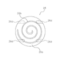
- FIG. 2 is a bottom view of the fixed scroll 24 viewed along the vertical direction.
- FIG. 3 is a top view of the movable scroll 26 viewed along the vertical direction.
- the fixed scroll 24 includes a first end plate 24a and a spiral-shaped first wrap 24b formed upright on the first end plate 24a.
- a main suction hole 24c is formed in the first end plate 24a.
- the main suction hole 24c is a space that connects the suction pipe 19 and a compression chamber 40 described later.
- the main suction hole 24 c forms a suction space for introducing a low-temperature and low-pressure refrigerant gas from the suction pipe 19 into the compression chamber 40.
- a discharge hole 41 is formed in the central portion of the first end plate 24a, and an enlarged recess 42 communicating with the discharge hole 41 is formed on the upper surface of the first end plate 24a.
- the enlarged recess 42 is a space recessed in the upper surface of the first end plate 24a.
- a lid 44 is fixed to the upper surface of the fixed scroll 24 by bolts 44 a so as to close the enlarged recess 42.
- the fixed scroll 24 and the lid 44 are sealed via a gasket (not shown).
- a muffler space 45 that silences the operation sound of the compression mechanism 15 is formed by covering the enlarged recess 42 with the lid 44.
- the fixed scroll 24 is formed with a first compressed refrigerant channel 46 that communicates with the muffler space 45 and opens on the lower surface of the fixed scroll 24. As shown in FIG. 2, a C-shaped oil groove 24e is formed on the lower surface of the first end plate 24a.
- the movable scroll 26 includes a disk-shaped second end plate 26a and a spiral second wrap 26b formed upright on the second end plate 26a.
- An upper end bearing 26c is formed at the center of the lower surface of the second end plate 26a.
- the movable scroll 26 has an oil supply hole 63 formed therein. The oil supply pore 63 communicates the outer peripheral portion of the upper surface of the second end plate 26a and the space inside the upper end bearing 26c.
- the fixed scroll 24 and the movable scroll 26 are surrounded by the first end plate 24a, the first wrap 24b, the second end plate 26a, and the second wrap 26b when the first wrap 24b and the second wrap 26b are engaged with each other.
- a compression chamber 40 that is a space is formed.
- the volume of the compression chamber 40 is gradually reduced by the revolving motion of the movable scroll 26.
- the lower surfaces of the first end plate 24 a and the first wrap 24 b of the fixed scroll 24 slide with the upper surfaces of the second end plate 26 a and the second wrap 26 b of the movable scroll 26.
- FIG. 4 is a bottom view of the fixed scroll 24 in which the second wrap 26 b of the movable scroll 26 and the compression chamber 40 are shown.
- the hatched area represents the thrust sliding surface 24d.
- the outer edge of the thrust sliding surface 24 d represents the locus of the outer edge of the second end plate 26 a of the revolving movable scroll 26.
- the oil groove 24e of the fixed scroll 24 is formed on the lower surface of the first end plate 24a so as to fit in the thrust sliding surface 24d.
- first key grooves 26d Two pairs of first key grooves 26d are formed on the lower surface of the second end plate 26a.
- the position of the first keyway 26d is indicated by a dotted line.
- each first key groove 26d is formed at a position separated by the same distance from the center of the second end plate 26a.
- the first key groove 26d is a groove into which the first key portion 39b of the Oldham joint 39 is fitted.
- the housing 23 is disposed below the compression mechanism 15.
- the outer peripheral surface of the housing 23 is joined to the inner peripheral surface of the body casing portion 11 in an airtight manner.
- the internal space of the casing 10 is partitioned into a high-pressure space S ⁇ b> 1 below the housing 23 and an upper space S ⁇ b> 2 that is a space above the housing 23.
- the housing 23 mounts a fixed scroll 24 and sandwiches a movable scroll 26 together with the fixed scroll 24.
- a second compressed refrigerant channel 48 is formed through the outer periphery of the housing 23 in the vertical direction.
- the second compressed refrigerant channel 48 communicates with the first compressed refrigerant channel 46 on the upper surface of the housing 23, and communicates with the high-pressure space S ⁇ b> 1 on the lower surface of the housing 23.
- the crank chamber S3 is recessed in the upper surface of the housing 23.
- a housing through hole 31 is formed in the housing 23.
- the housing through hole 31 penetrates the housing 23 in the vertical direction from the center of the bottom surface of the crank chamber S3 to the center of the lower surface of the housing 23.
- a portion that is a part of the housing 23 and in which the housing through hole 31 is formed is referred to as an upper bearing 32.
- the housing 23 is formed with an oil return passage 23a that connects the high-pressure space S1 near the inner peripheral surface of the casing 10 and the crank chamber S3.
- a pair of second key grooves 23 d are formed on the upper surface of the housing 23. When the housing 23 is viewed along the vertical direction, each second key groove 23 d is formed at a position away from the center of the housing through hole 31 by the same distance.
- the second key groove 23d is a groove into which the second key portion 39c of the Oldham joint 39 is fitted.
- FIG. 5 is an enlarged view of the vicinity of the Oldham coupling 39 of FIG. 6 is a cross-sectional view taken along line VI-VI in FIG. As shown in FIGS. 5 and 6, the Oldham coupling 39 is installed between the movable scroll 26 and the housing 23.
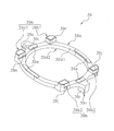
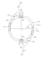
- FIG. 7 is a perspective view of the Oldham coupling 39.
- FIG. 8 is a top view of the Oldham coupling 39.
- the Oldham coupling 39 is mainly an annular member having an annular main body 39a, two pairs of first key parts 39b, and a pair of second key parts 39c.
- the annular main body 39a has a first horizontal surface 39d1 and a second horizontal surface 39d2 that face each other.
- the first horizontal plane 39d1 and the second horizontal plane 39d2 are planes parallel to the horizontal plane.
- the first horizontal plane 39d1 is located above the second horizontal plane 39d2. 7 and 8, the second horizontal surface 39d2 is a surface on the back side of the first horizontal surface 39d1.
- a plurality of sliding protrusions 39e are formed on the first horizontal surface 39d1.
- the upper surface of the sliding protrusion 39e is parallel to the first horizontal surface 39d1.
- the first key portion 39b is a convex portion that protrudes upward from the first horizontal surface 39d1.
- the first key portion 39 b is fitted into the first key groove 26 d of the movable scroll 26.
- the second key portion 39c is a convex portion that protrudes downward from the second horizontal surface 39d2.
- the second key portion 39 c is fitted into the second key groove 23 d of the housing 23.
- the position of the second key portion 39c is indicated by a dotted line.
- FIG. 8 shows a first axis A1 and a second axis A2 parallel to the horizontal plane.
- the first axis A1 and the second axis A2 pass through the center of gravity O of the Oldham joint 39 and are orthogonal to each other.
- the four first key portions 39b are formed one by one in each of the four regions defined by the first axis A1 and the second axis A2.
- Two second key portions are formed one by one in each of the two regions defined by the second axis A2.
- the four first key portions 39b will be described by distinguishing between a pair of the first key portion 39b1 and a pair of the first key portion 39b2.
- the pair of first key portions 39b1 are formed at symmetrical positions with respect to the first axis A1.
- the pair of first key portions 39b2 are formed at positions that are symmetric with respect to the first axis A1.
- the pair of the first key part 39b1 and the pair of the first key part 39b2 are formed at positions that are symmetrical with respect to the second axis A2.
- the pair of second key portions 39c are formed at positions symmetrical with respect to the second axis A2.
- Each second key portion 39c is formed on the first axis A1 at a position that is symmetric with respect to the first axis A1.
- the first key portion 39b has a first sliding surface 39h and a first guide surface 39j.
- the first sliding surface 39h and the first guide surface 39j are side surfaces of the first key portion 39b and are surfaces parallel to the second axis A2.
- the first sliding surface 39h is the surface closer to the center of gravity O of the Oldham joint 39
- the first guide surface 39j is the center of gravity O of the Oldham joint 39. It is the surface far from the surface.
- the first sliding surface 39h is a surface that slides with the inner peripheral surface of the first key groove 26d along the second axis A2.
- the first sliding surface 39 h is a surface that receives a surface pressure from the movable scroll 26.
- the second key portion 39c has a second sliding surface 39i that is a side surface parallel to the first axis A1.
- the second sliding surfaces 39i are a pair of side surfaces of the second key portion 39c, and are surfaces parallel to the first axis A1.
- the second sliding surface 39i is a surface that slides with the inner peripheral surface of the second key groove 23d along the first axis A1.
- the second sliding surface 39 i is a surface that receives a surface pressure from the housing 23.
- the Oldham coupling 39 is movable relative to the housing 23 along the first axis A1, and is movable relative to the movable scroll 23 along the second axis A2. While the Oldham joint 39 is moving relative to the movable scroll 23, the upper surface of the sliding projection 39 e of the Oldham joint 39 slides with the lower surface of the second end plate 26 a of the movable scroll 26.
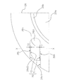
- FIG. 9 is a top view showing the first key portion 39b fitted in the first key groove 26d at the upper left shown in FIG. 10 is a cross-sectional view taken along line XX in FIG.
- the first sliding surface 39h of the first key portion 39b is a surface facing the first key groove inner side surface 26d1 of the first key groove 26d.
- the first guide surface 39j of the first key portion 39b is a surface facing the first key groove outer surface 26d2 of the first key groove 26d.
- the first keyway inner side surface 26d1 and the first keyway outer side surface 26d2 are surfaces parallel to the second axis A2.
- the first key portion 39b has a first upper end surface 39k.
- the first upper end surface 39k is a surface facing the first key groove bottom surface 26d3 of the first key groove 26d.
- the first key groove bottom surface 26d3 corresponds to the bottom surface of the first key groove 26d.
- the first key groove 26d is a groove formed on the lower surface of the housing 23, as shown in FIG. 10, the first key groove bottom surface 26d3 includes the first key groove inner surface 26d1 and the first key groove. It is connected to the upper end of the outer side surface 26d2.
- a space called a key gap 70 exists between the outer peripheral surface of the first key portion 39b and the inner peripheral surface of the first key groove 26d.
- the key gap 70 mainly has a first gap 71, a second gap 72, and a third gap 73.
- the first gap 71 is a gap between the first sliding surface 39h of the first key portion 39b and the first key groove inner side surface 26d1 of the first key groove 26d.
- the second gap 72 is a gap between the first guide surface 39j of the first key portion 39b and the first key groove outer surface 26d2 of the first key groove 26d.
- the third gap 73 is a gap between the first upper end face 39k of the first key portion 39b and the first key groove bottom face 26d3 of the first key groove 26d.
- the dimension D1 of the first gap 71 is 15 ⁇ m to 50 ⁇ m.
- the dimension D2 of the second gap 72 is 200 ⁇ m to 1000 ⁇ m.
- the dimension D3 of the third gap 73 is 200 ⁇ m to 1000 ⁇ m.
- a dimension D1 of the first gap 71 is a distance between the first sliding surface 39h and the first keyway inner side surface 26d1 in a direction parallel to the first axis A1.
- the dimension D2 of the second gap 72 is a distance between the first guide surface 39j and the first keyway outer surface 26d2 in a direction parallel to the first axis A1.
- a dimension D3 of the third gap 73 is a distance between the first upper end surface 39k and the first key groove bottom surface 26d3 in the vertical direction.
- the second gap 72 is wider than the first gap 71. That is, the dimension D2 of the second gap 72 is larger than the dimension D1 of the first gap 71.
- the drive motor 16 is a brushless DC motor disposed below the housing 23.
- the drive motor 16 mainly includes a stator 51 and a rotor 52.
- the stator 51 is a cylindrical member fixed to the inner peripheral surface of the casing 10.
- the rotor 52 is a cylindrical member disposed inside the stator 51.
- An air gap is formed between the inner peripheral surface of the stator 51 and the outer peripheral surface of the rotor 52.
- a plurality of core cuts are formed on the outer peripheral surface of the stator 51.
- the core cut is a groove formed in the vertical direction from the upper end surface to the lower end surface of the stator 51.
- the core cuts are formed at predetermined intervals along the circumferential direction of the stator 51.
- the core cut forms a motor cooling passage 55 that extends in the vertical direction between the body casing portion 11 and the stator 51.
- the rotor 52 is connected to the crankshaft 17.
- the crankshaft 17 penetrates the rotation center of the rotor 52 in the vertical direction.
- the rotor 52 is connected to the compression mechanism 15 via the crankshaft 17.
- the lower bearing 60 is disposed below the drive motor 16.
- the outer peripheral surface of the lower bearing 60 is joined to the inner peripheral surface of the casing 10 in an airtight manner.
- the lower bearing 60 supports the crankshaft 17.
- An oil separation plate 73 is attached to the lower bearing 60.
- the oil separation plate 73 is a flat plate member accommodated in the casing 10. The oil separation plate 73 is fixed to the upper end surface of the lower bearing 60.
- crankshaft 17 is housed inside the casing 10.
- the crankshaft 17 is arranged so that its axial direction is along the vertical direction.
- the axial center of the upper end portion of the crankshaft 17 is slightly eccentric with respect to the axial center of the portion excluding the upper end portion.
- the crankshaft 17 has a balance weight 18.
- the balance weight 18 is fixed in close contact with the crankshaft 17 at a height position below the housing 23 and above the drive motor 16.
- the crankshaft 17 is connected to the rotor 52 through the rotation center of the rotor 52 in the vertical direction.
- the crankshaft 17 is connected to the movable scroll 26 by fitting the upper end portion of the crankshaft 17 into the upper end bearing 26 c.
- the crankshaft 17 is supported by the upper bearing 32 and the lower bearing 60.
- the crankshaft 17 has a main oil supply passage 61 extending in its axial direction.
- the upper end of the main oil supply passage 61 communicates with an oil chamber 83 formed by the upper end surface of the crankshaft 17 and the lower surface of the second end plate 26a.
- the oil chamber 83 communicates with the thrust sliding surface 24d and the oil groove 24e via the oil supply hole 63 of the second end plate 26a, and finally communicates with the low pressure space S2 via the compression chamber 40.
- the lower end of the main oil supply passage 61 is immersed in the lubricating oil in the oil reservoir space 10a.
- the crankshaft 17 has a first sub oil supply path 61a, a second sub oil supply path 61b, and a third sub oil supply path 61c branched from the main oil supply path 61.
- the first sub oil supply path 61a, the second sub oil supply path 61b, and the third sub oil supply path 61c extend in the horizontal direction.
- the first sub oil supply passage 61 a is open to the sliding surface between the crankshaft 17 and the upper end bearing 26 c of the movable scroll 26.
- the second sub oil supply passage 61 b opens in the sliding surface between the crankshaft 17 and the upper bearing 32 of the housing 23.
- the third sub oil supply passage 61 c is open on the sliding surface between the crankshaft 17 and the lower bearing 60.
- the suction pipe 19 is a pipe for introducing the refrigerant of the refrigerant circuit from the outside of the casing 10 to the compression mechanism 15.
- the suction pipe 19 is fitted into the upper wall portion 12 of the casing 10 in an airtight manner.
- the suction pipe 19 penetrates the upper space S ⁇ b> 2 in the vertical direction, and an inner end portion is fitted into the main suction hole 24 c of the fixed scroll 24.
- the discharge pipe 20 is a pipe for discharging the compressed refrigerant from the high-pressure space S1 to the outside of the casing 10.
- the discharge pipe 20 is fitted in the body casing part 11 of the casing 10 in an airtight manner.
- the discharge pipe 20 penetrates the high-pressure space S1 in the horizontal direction.
- the opening 20 a of the discharge pipe 20 is located in the vicinity of the housing 23.
- the movable scroll 26 is engaged with the housing 23 via an Oldham joint 39.
- the first key portion 39b of the Oldham joint 39 slides along the second axis A2 in the first key groove 26d of the movable scroll 26, and the second key portion 39c of the Oldham joint 39 Then, it slides in the second keyway 23d of the housing 23 along the first axis A1.
- the movable scroll 26 performs a revolving motion with respect to the fixed scroll 24 without rotating.
- the low-temperature and low-pressure refrigerant before being compressed is supplied from the suction pipe 19 to the compression chamber 40 of the compression mechanism 15 via the main suction hole 24c.
- the compression chamber 40 moves from the outer peripheral portion of the fixed scroll 24 toward the center portion while gradually reducing the volume.
- the refrigerant in the compression chamber 40 is compressed to become a compressed refrigerant.
- the compressed refrigerant is discharged from the discharge hole 41 to the muffler space 45, and then discharged to the high-pressure space S1 via the first compressed refrigerant channel 46 and the second compressed refrigerant channel 48.
- the compressed refrigerant descends the motor cooling passage 55 and reaches the high pressure space S ⁇ b> 1 below the drive motor 16. Thereafter, the compressed refrigerant reverses the flow direction, and raises the air gap of the other motor cooling passage 55 and the drive motor 16. Finally, the compressed refrigerant is discharged from the discharge pipe 20 to the outside of the scroll compressor 101.
- the lubricating oil flowing through the third auxiliary oil supply passage 61c lubricates the sliding surfaces of the crankshaft 17 and the lower bearing 60, and then flows into the high-pressure space S1 and returns to the oil pool space 10a.
- the lubricating oil flowing through the second auxiliary oil supply passage 61b lubricates the sliding surface between the crankshaft 17 and the upper bearing 32 of the housing 23, and then flows into the high-pressure space S1 and the crank chamber S3.
- the lubricating oil that has flowed into the high-pressure space S1 returns to the oil reservoir space 10a.
- the lubricating oil that has flowed into the crank chamber S3 flows into the high-pressure space S1 via the oil return passage 23a of the housing 23 and returns to the oil reservoir space 10a.
- the lubricating oil flowing through the first auxiliary oil supply passage 61a lubricates the sliding surface between the crankshaft 17 and the upper end bearing 26c of the movable scroll 26, and then flows into the crank chamber S3 and is stored in the oil reservoir via the high-pressure space S1. Return to space 10a.
- the lubricating oil mixed in the compressed refrigerant is discharged from the compression chamber 40 to the high-pressure space S1 through the same path as the compressed refrigerant. Thereafter, the lubricating oil collides with the oil separation plate 73 after descending the motor cooling passage 55 together with the compressed refrigerant. The lubricating oil adhering to the oil separation plate 73 falls in the high pressure space S1 and returns to the oil reservoir space 10a.
- the Oldham coupling 39 includes a first key portion 39 b that slides with the movable scroll 26 and a second key portion 39 c that slides with the housing 23.
- the first key portion 39b has a first sliding surface 39h and a first guide surface 39j that move along the second axis A2.
- the first sliding surface 39h is a surface closer to the center of gravity O of the Oldham joint 39 than the first guide surface 39j.
- the first sliding surface 39h is a surface that slides with the first keyway inner side surface 26d1 of the first keyway 26d of the movable scroll 26.
- a first gap 71 is formed between the first sliding surface 39h of the first key portion 39b and the first key groove inner side surface 26d1 of the first key groove 26d.
- a second gap 72 is formed between the first guide surface 39j of the first key portion 39b and the first keyway outer surface 26d2 of the first keyway 26d.
- the first gap 71 and the second gap 72 are spaces in which the lubricating oil supplied to the first key groove 26d is held. The lubricating oil suppresses seizure between the first sliding surface 39h and the first keyway inner side surface 26d1 that slide with each other.
- the scroll compressor 101 Since the second gap 72 is wider than the first gap 71, the lubricating oil supplied to the first key groove 26d is easier to hold than the first gap 71. As a result, a part of the lubricating oil held in the second gap 72 passes through the key gap 70 between the outer peripheral surface of the first key portion 39b and the inner peripheral surface of the first key groove 26d. It is supplied to the gap 71. Therefore, even if the lubricating oil present in the first gap 71 is insufficient, a part of the lubricating oil present in the second gap 72 is supplied to the first gap 71, so that the first sliding of the first key portion 39b. Burn-in of the surface 39h is suppressed. Therefore, the scroll compressor 101 has high reliability by suppressing seizure of the sliding surfaces of the Oldham joint 39 and the movable scroll 26.
- the dimension D1 of the first gap 71 is 15 ⁇ m to 50 ⁇ m.
- the dimension D1 of the first gap 71 is so narrow that rattling of the sliding Oldham coupling 39 is sufficiently suppressed, and the amount of lubrication is sufficient to prevent the seizure of the first sliding surface 39h. Wide enough to retain oil. If the dimension D1 of the first gap 71 is too wide, the Oldham joint 39 sliding along the second axis A2 may vibrate in the direction of the first axis A1, and the Oldham joint 39 may rattle. In addition, if the dimension D1 of the first gap 71 is too narrow, the lubricating oil is not sufficiently held in the first gap 71, and the first sliding surface 39h may be seized.
- the dimension D2 of the second gap 72 is 200 ⁇ m to 1000 ⁇ m. Since the dimension D2 of the second gap 72 is larger than the dimension D1 of the first gap 71, the second gap 72 can hold a larger amount of lubricating oil than the first gap 71. As a result, a part of the lubricating oil held in the second gap 72 passes through the key gap 70 between the outer peripheral surface of the first key portion 39b and the inner peripheral surface of the first key groove 26d. It is supplied to the gap 71. Accordingly, by setting the dimension D2 of the second gap 72 within an appropriate range, the first sliding surface 39h of the first key portion 39b is seized due to insufficient lubricating oil being supplied to the first gap 71. Is suppressed.
- the pair of second key portions 39c are provided on the first axis A1 across the second axis A2. That is, when the Oldham joint 39 is viewed from above, the two second key portions 39c are arranged as far as possible from each other. Therefore, the surface pressure applied to the sliding surface of the second key portion 39c is evenly distributed between the two second key portions 39c. Therefore, the occurrence of seizure only on the sliding surfaces of some of the second key portions 39c is suppressed.
- the Oldham coupling 39 mainly includes an annular main body 39a, two pairs of first key portions 39b, and a pair of second key portions 39c.
- the two pairs of first key portions 39b include a pair of first key portions 39b1 and a pair of first key portions 39b2.
- the pair of first key portions 39b1 are formed at positions that are symmetric with respect to the first axis A1.
- the pair of first key portions 39b2 are formed at positions that are symmetric with respect to the first axis A1.
- the pair of the first key part 39b1 and the pair of the first key part 39b2 are formed at positions that are symmetrical with respect to the second axis A2.
- Oldham coupling 39 may have only one of a pair of first key portions 39b1 and only one of a pair of first key portions 39b2 instead of having two pairs of first key portions 39b.
- the first key portion 39b of the Oldham joint 39 may be configured by only one first key portion 39b1 and one first key portion 39b2.
- FIGS. 11 and 12 are top views of the Oldham coupling 39 of the present modification. 11 and 12, the Oldham coupling 39 has one first key portion 39b1 and one first key portion 39b2.
- the two first key portions 39 b 1 and 39 b 2 are formed at positions that are symmetric with respect to the center of gravity O of the Oldham joint 39.
- the two first key portions 39b1 and 39b2 are formed at symmetrical positions with respect to the second axis A2.
- the two first key portions 39b1 and 39b2 may be formed at positions that are symmetric with respect to the position shown in FIGS. 11 and 12 and the first axis A1.
- the scroll compressor 101 has high reliability by suppressing seizure of the sliding surfaces of the Oldham joint 39 and the movable scroll 26.
- the Oldham coupling 39 may have at least two first key portions 39b among the four first key portions 39b shown in FIG. That is, the Oldham coupling 39 may have two or three first key portions 39b.
- the first key part 39b is provided in one of the four areas defined by the first axis A1 and the second axis A2, and two or more first key parts 39b are provided in the same area. Not provided.
- FIGS. 13 and 14 are top views of the Oldham coupling 39 of the present modification.
- the shape of the inner peripheral surface of the annular main body portion 39a is a straight portion IE parallel to the second axis A2. Is included.
- the shape of the inner peripheral surface of the annular main body portion 39a is a straight portion IE that is not parallel to the second axis A2. Is included.
- the first key part 39b of the Oldham coupling 39 may be composed of only one first key part 39b1 and one first key part 39b2, as in Modification A.
- the scroll compressor according to the present invention has high reliability by suppressing seizure of the sliding surface of the Oldham joint and the movable scroll.
Landscapes
- Engineering & Computer Science (AREA)
- Mechanical Engineering (AREA)
- General Engineering & Computer Science (AREA)
- Rotary Pumps (AREA)
Abstract
本発明に係るスクロール圧縮機は、オルダム継手および可動スクロールの摺動面の焼き付きを抑制して、高い信頼性を有する。スクロール圧縮機(101)は、第1キー溝(26d)を有する可動スクロール(26)と、第2キー溝(23d)を有するハウジング(23)と、可動スクロール(26)とハウジング(23)との間のオルダム継手(39)とを備える。オルダム継手(39)は、環状本体部(39a)と、第1キー溝(26d)に嵌め込まれる2対の第1キー部(39b)と、第2キー溝(23d)に嵌め込まれる第2キー部(39c)とを有する。第1キー部(39b)の外周面と、第1キー溝(26d)の内周面との間には、キー隙間(70)が形成される。キー隙間(70)は、オルダム継手(39)の径方向内側の第1隙間(71)と、径方向外側の第2隙間(72)とを有する。第2隙間(72)は、第1隙間(71)よりも広いので、第1隙間(71)よりも多量の潤滑油を保持することができる。
Description
本発明は、可動スクロールの自転を防止するためのオルダム継手を備えるスクロール圧縮機に関する。
冷凍装置等に用いられるスクロール圧縮機は、固定スクロールおよび可動スクロールを備える。固定スクロールおよび可動スクロールは、それぞれ、渦巻き部を有する。可動スクロールの渦巻き部が固定スクロールの渦巻き部と噛み合うことで、冷媒ガス等の流体が圧縮される空間である圧縮室が形成される。スクロール圧縮機は、可動スクロールを公転させて圧縮室の容積を変化させることで流体を圧縮する。
通常、スクロール圧縮機は、運転中における可動スクロールの自転を防止するためのオルダム継手を備える。オルダム継手は、可動スクロールと、ハウジング等の固定部材との間に設置される。特許文献1(特表2011-510209号公報)に開示されているように、オルダム継手は、環状の本体部と、本体部から鉛直方向に突出しているキー部とを有する。各キー部は、可動スクロールまたは固定部材と摺動する面を有する。オルダム継手と可動スクロールとの間の摺動部、および、オルダム継手と固定部材との間の摺動部には、摺動面の焼き付きを防止するための潤滑油が供給される。摺動部に潤滑油が十分に供給されていないと、摺動面が高温になり焼き付きが生じるおそれがある。
しかし、特許文献1(特表2011-510209号公報)に開示されるようなオルダム継手の場合、キー部の側面の一つのみが、可動スクロールの外周面と摺動する。そのため、オルダム継手と可動スクロールとの間の摺動部に供給された潤滑油が漏れ出して、摺動部に潤滑油が十分に供給されていない状態になりやすい。これにより、オルダム継手および可動スクロールの摺動面が焼き付いて、圧縮機の信頼性が低下するおそれがある。
本発明の目的は、オルダム継手および可動スクロールの摺動面の焼き付きを抑制して、高い信頼性を有するスクロール圧縮機を提供することである。
本発明の第1観点に係るスクロール圧縮機は、可動スクロールと、静止部材と、オルダム継手とを備える。可動スクロールは、第1キー溝を有する。静止部材は、第2キー溝を有する。オルダム継手は、可動スクロールと静止部材との間に設けられる。オルダム継手は、第1軸に沿って静止部材に対して相対的に移動可能であり、第2軸に沿って可動スクロールに対して相対的に移動可能である。オルダム継手は、環状本体部と、2対の第1キー部と、第2キー部とを有する。環状本体部は、互いに対向する第1水平面および第2水平面を有する。第1キー部は、第1水平面から突出し、第1キー溝に嵌め込まれる。第1キー部は、第2軸に沿って可動スクロールと摺動可能である。第2キー部は、第2水平面から突出し、第2キー溝に嵌め込まれる。第2キー部は、第1軸に沿って静止部材と摺動可能である。第1キー部の外周面と、第1キー溝の内周面との間には、キー隙間が形成される。キー隙間は、第1隙間と、第2隙間とを有する。第1隙間は、オルダム継手の重心側において第2軸に沿って形成される。第2隙間は、オルダム継手の重心側の反対側において第2軸に沿って形成される。第2隙間は、第1隙間よりも広い。
このスクロール圧縮機では、オルダム継手の第1キー部は、オルダム継手の径方向内側の側面である摺動面と、径方向外側の側面であるガイド面とを有する。第1キー部の摺動面は、可動スクロールと摺動する面であり、可動スクロールの第1キー溝の内周面との間に第1隙間を形成する。第1キー部のガイド面は、可動スクロールの第1キー溝の内周面との間に第2隙間を形成する。第2隙間は、第1隙間よりも広いので、第1キー溝に供給された潤滑油を第1隙間よりも保持しやすい。これにより、第2隙間に保持されている潤滑油の一部が第1隙間に供給され、第1キー部の摺動面の焼き付きが抑制される。従って、このスクロール圧縮機は、オルダム継手および可動スクロールの摺動面の焼き付きを抑制することで、高い信頼性を有する。
本発明の第2観点に係るスクロール圧縮機は、第1観点に係るスクロール圧縮機であって、第1隙間は、15μm~50μmである。
このスクロール圧縮機では、第1キー部の摺動面と、第1キー溝の内周面との間の第1隙間は、摺動しているオルダム継手のがたつきが十分に抑制される程度に狭く、かつ、摺動面の焼き付きが十分に抑制される量の潤滑油が保持される程度に広い。そのため、第1隙間に潤滑油が十分に供給されないことによる摺動面の焼き付きの発生が抑制される。
本発明の第3観点に係るスクロール圧縮機は、第1観点または第2観点に係るスクロール圧縮機であって、第2隙間は、200μm~1000μmである。
このスクロール圧縮機では、第1キー部のガイド面と、第1キー溝の内周面との間の第2隙間は、第1隙間よりも多量の潤滑油を保持することができる。これにより、第2隙間に保持されている潤滑油の一部は、第1キー部の外周面と第1キー溝の内周面との間の隙間を介して、第1隙間に供給される。そのため、第1隙間に潤滑油が十分に供給されないことによる摺動面の焼き付きの発生が抑制される。
本発明の第4観点に係るスクロール圧縮機は、第1乃至第3観点のいずれか1つに係るスクロール圧縮機であって、第1キー部は、第1軸および第2軸によって区画される4つの領域のそれぞれに、1つずつ設けられる。
このスクロール圧縮機では、オルダム継手を上面視した場合に、4つの第1キー部は、できるだけ互いに離れるように配置されている。そのため、第1キー部の摺動面にかかる面圧は、4つの第1キー部の間で均等に分散される。従って、一部の第1キー部の摺動面のみに焼き付きが発生することが抑制される。
本発明の第5観点に係るスクロール圧縮機は、第4観点に係るスクロール圧縮機であって、オルダム継手は、1対の第2キー部を有する。第2キー部は、第2軸を挟んで、第1軸の上に設けられる。
このスクロール圧縮機では、オルダム継手を上面視した場合に、2つの第2キー部は、できるだけ互いに離れるように配置されている。そのため、第2キー部の摺動面にかかる面圧は、2つの第2キー部の間で均等に分散される。従って、一部の第2キー部の摺動面のみに焼き付きが発生することが抑制される。
本発明の第6観点に係るスクロール圧縮機は、可動スクロールと、静止部材と、オルダム継手とを備える。可動スクロールは、第1キー溝を有する。静止部材は、第2キー溝を有する。オルダム継手は、可動スクロールと静止部材との間に設けられる。オルダム継手は、第1軸に沿って静止部材に対して相対的に移動可能であり、第2軸に沿って可動スクロールに対して相対的に移動可能である。オルダム継手は、環状本体部と、少なくとも2つの第1キー部と、第2キー部とを有する。環状本体部は、互いに対向する第1水平面および第2水平面を有する。第1キー部は、第1水平面から突出し、第1キー溝に嵌め込まれる。第1キー部は、第2軸に沿って可動スクロールと摺動可能である。第2キー部は、第2水平面から突出し、第2キー溝に嵌め込まれる。第2キー部は、第1軸に沿って静止部材と摺動可能である。第1キー部の外周面と、第1キー溝の内周面との間には、キー隙間が形成される。キー隙間は、第1隙間と、第2隙間とを有する。第1隙間は、オルダム継手の重心側において第2軸に沿って形成される。第2隙間は、オルダム継手の重心側の反対側において第2軸に沿って形成される。第2隙間は、第1隙間よりも広い。
本発明に係るスクロール圧縮機は、オルダム継手および可動スクロールの摺動面の焼き付きを抑制して、高い信頼性を有する。
本発明の実施形態に係るスクロール圧縮機101について、図面を参照しながら説明する。スクロール圧縮機101は、空気調和装置等の冷凍装置に用いられる。スクロール圧縮機101は、冷凍装置の冷媒回路を循環する冷媒ガスを圧縮する。
(1)スクロール圧縮機の構成
スクロール圧縮機101は、高低圧ドーム型のスクロール圧縮機である。スクロール圧縮機101は、互いに噛み合う渦巻き形状のラップを有する2つのスクロール部材を用いて冷媒を圧縮する。
スクロール圧縮機101は、高低圧ドーム型のスクロール圧縮機である。スクロール圧縮機101は、互いに噛み合う渦巻き形状のラップを有する2つのスクロール部材を用いて冷媒を圧縮する。
図1は、スクロール圧縮機101の縦断面図である。図1において、矢印Uは、鉛直方向に沿って上方を指す。スクロール圧縮機101は、主として、ケーシング10と、圧縮機構15と、ハウジング23と、オルダム継手39と、駆動モータ16と、下部軸受60と、クランクシャフト17と、吸入管19と、吐出管20とから構成される。次に、スクロール圧縮機101の各構成要素について説明する。
(1-1)ケーシング
ケーシング10は、円筒状の胴部ケーシング部11と、椀状の上壁部12と、椀状の底壁部13とから構成される。上壁部12は、胴部ケーシング部11の上端部に気密状に溶接される。底壁部13は、胴部ケーシング部11の下端部に気密状に溶接される。
ケーシング10は、円筒状の胴部ケーシング部11と、椀状の上壁部12と、椀状の底壁部13とから構成される。上壁部12は、胴部ケーシング部11の上端部に気密状に溶接される。底壁部13は、胴部ケーシング部11の下端部に気密状に溶接される。
ケーシング10は、ケーシング10の内部および外部において圧力や温度が変化した場合に、変形および破損が起こりにくい剛性部材で成型されている。ケーシング10は、胴部ケーシング部11の円筒形状の軸方向が鉛直方向に沿うように設置される。
ケーシング10の内部には、主として、圧縮機構15と、ハウジング23と、オルダム継手39と、駆動モータ16と、下部軸受60と、クランクシャフト17とが収容されている。ケーシング10の壁部には、吸入管19および吐出管20が気密状に溶接されている。
ケーシング10の底部には、潤滑油が貯留される油溜まり空間10aが形成されている。潤滑油は、スクロール圧縮機101の運転中において、圧縮機構15等の摺動部の潤滑性を良好に保つために使用される冷凍機油である。
(1-2)圧縮機構
圧縮機構15は、ケーシング10の内部に収容される。圧縮機構15は、低温低圧の冷媒ガスを吸引して圧縮し、高温高圧の冷媒ガス(以下、「圧縮冷媒」という。)を吐出する。圧縮機構15は、主として、固定スクロール24と、可動スクロール26とから構成される。固定スクロール24は、ケーシング10に対して固定されている。可動スクロール26は、固定スクロール24に対して公転運動を行う。図2は、鉛直方向に沿って視た固定スクロール24の下面図である。図3は、鉛直方向に沿って視た可動スクロール26の上面図である。
圧縮機構15は、ケーシング10の内部に収容される。圧縮機構15は、低温低圧の冷媒ガスを吸引して圧縮し、高温高圧の冷媒ガス(以下、「圧縮冷媒」という。)を吐出する。圧縮機構15は、主として、固定スクロール24と、可動スクロール26とから構成される。固定スクロール24は、ケーシング10に対して固定されている。可動スクロール26は、固定スクロール24に対して公転運動を行う。図2は、鉛直方向に沿って視た固定スクロール24の下面図である。図3は、鉛直方向に沿って視た可動スクロール26の上面図である。
(1-2-1)固定スクロール
固定スクロール24は、第1鏡板24aと、第1鏡板24aに直立して形成される渦巻き形状の第1ラップ24bとを有する。第1鏡板24aには、主吸入孔24cが形成されている。主吸入孔24cは、吸入管19と、後述する圧縮室40とを接続する空間である。主吸入孔24cは、低温低圧の冷媒ガスを吸入管19から圧縮室40に導入するための吸入空間を形成する。第1鏡板24aの中央部には、吐出孔41が形成され、第1鏡板24aの上面には、吐出孔41と連通する拡大凹部42が形成されている。拡大凹部42は、第1鏡板24aの上面に凹設された空間である。固定スクロール24の上面には、拡大凹部42を塞ぐように蓋体44がボルト44aによって固定されている。固定スクロール24および蓋体44は、ガスケット(図示せず)を介してシールされている。拡大凹部42に蓋体44が覆い被せられることにより、圧縮機構15の運転音を消音させるマフラー空間45が形成されている。固定スクロール24には、マフラー空間45と連通し、固定スクロール24の下面に開口する第1圧縮冷媒流路46が形成されている。第1鏡板24aの下面には、図2に示されるように、C字形状の油溝24eが形成されている。
固定スクロール24は、第1鏡板24aと、第1鏡板24aに直立して形成される渦巻き形状の第1ラップ24bとを有する。第1鏡板24aには、主吸入孔24cが形成されている。主吸入孔24cは、吸入管19と、後述する圧縮室40とを接続する空間である。主吸入孔24cは、低温低圧の冷媒ガスを吸入管19から圧縮室40に導入するための吸入空間を形成する。第1鏡板24aの中央部には、吐出孔41が形成され、第1鏡板24aの上面には、吐出孔41と連通する拡大凹部42が形成されている。拡大凹部42は、第1鏡板24aの上面に凹設された空間である。固定スクロール24の上面には、拡大凹部42を塞ぐように蓋体44がボルト44aによって固定されている。固定スクロール24および蓋体44は、ガスケット(図示せず)を介してシールされている。拡大凹部42に蓋体44が覆い被せられることにより、圧縮機構15の運転音を消音させるマフラー空間45が形成されている。固定スクロール24には、マフラー空間45と連通し、固定スクロール24の下面に開口する第1圧縮冷媒流路46が形成されている。第1鏡板24aの下面には、図2に示されるように、C字形状の油溝24eが形成されている。
(1-2-2)可動スクロール
可動スクロール26は、円盤形状の第2鏡板26aと、第2鏡板26aに直立して形成される渦巻き形状の第2ラップ26bとを有する。第2鏡板26aの下面中央部には、上端軸受26cが形成されている。可動スクロール26には、給油細孔63が形成されている。給油細孔63は、第2鏡板26aの上面外周部と、上端軸受26cの内側の空間とを連通している。
可動スクロール26は、円盤形状の第2鏡板26aと、第2鏡板26aに直立して形成される渦巻き形状の第2ラップ26bとを有する。第2鏡板26aの下面中央部には、上端軸受26cが形成されている。可動スクロール26には、給油細孔63が形成されている。給油細孔63は、第2鏡板26aの上面外周部と、上端軸受26cの内側の空間とを連通している。
固定スクロール24および可動スクロール26は、第1ラップ24bと第2ラップ26bとが噛み合うことにより、第1鏡板24aと、第1ラップ24bと、第2鏡板26aと、第2ラップ26bとによって囲まれる空間である圧縮室40を形成する。圧縮室40の容積は、可動スクロール26の公転運動によって徐々に減少する。可動スクロール26の公転中に、固定スクロール24の第1鏡板24aおよび第1ラップ24bの下面は、可動スクロール26の第2鏡板26aおよび第2ラップ26bの上面と摺動する。以下、可動スクロール26と摺動する第1鏡板24aの表面を、スラスト摺動面24dと呼ぶ。図4は、可動スクロール26の第2ラップ26bおよび圧縮室40が示された固定スクロール24の下面図である。図4において、ハッチングされた領域は、スラスト摺動面24dを表す。図4において、スラスト摺動面24dの外縁は、公転する可動スクロール26の第2鏡板26aの外縁の軌跡を表す。図4に示されるように、固定スクロール24の油溝24eは、スラスト摺動面24dに納まるように第1鏡板24aの下面に形成されている。
第2鏡板26aの下面には、2対の第1キー溝26dが形成されている。図3には、第1キー溝26dの位置が点線で示されている。可動スクロール26を鉛直方向に沿って視た場合、各第1キー溝26dは、第2鏡板26aの中心から同じ距離だけ離れた位置に形成されている。第1キー溝26dは、オルダム継手39の第1キー部39bが嵌め込まれる溝である。
(1-3)ハウジング
ハウジング23は、圧縮機構15の下方に配置されている。ハウジング23の外周面は、胴部ケーシング部11の内周面に気密状に接合されている。これにより、ケーシング10の内部空間は、ハウジング23の下方の高圧空間S1と、ハウジング23の上方の空間である上部空間S2とに区画されている。ハウジング23は、固定スクロール24を載置し、固定スクロール24と共に可動スクロール26を挟み込んでいる。ハウジング23の外周部には、第2圧縮冷媒流路48が鉛直方向に貫通して形成されている。第2圧縮冷媒流路48は、ハウジング23の上面において第1圧縮冷媒流路46と連通し、ハウジング23の下面において高圧空間S1と連通する。
ハウジング23は、圧縮機構15の下方に配置されている。ハウジング23の外周面は、胴部ケーシング部11の内周面に気密状に接合されている。これにより、ケーシング10の内部空間は、ハウジング23の下方の高圧空間S1と、ハウジング23の上方の空間である上部空間S2とに区画されている。ハウジング23は、固定スクロール24を載置し、固定スクロール24と共に可動スクロール26を挟み込んでいる。ハウジング23の外周部には、第2圧縮冷媒流路48が鉛直方向に貫通して形成されている。第2圧縮冷媒流路48は、ハウジング23の上面において第1圧縮冷媒流路46と連通し、ハウジング23の下面において高圧空間S1と連通する。
ハウジング23の上面には、クランク室S3が凹設されている。ハウジング23には、ハウジング貫通孔31が形成されている。ハウジング貫通孔31は、クランク室S3の底面中央部から、ハウジング23の下面中央部まで、ハウジング23を鉛直方向に貫通している。以下、ハウジング23の一部であり、かつ、ハウジング貫通孔31が形成されている部分を、上部軸受32という。ハウジング23には、ケーシング10の内周面近傍の高圧空間S1とクランク室S3とを連通する油戻し通路23aが形成されている。
ハウジング23の上面には、1対の第2キー溝23dが形成されている。ハウジング23を鉛直方向に沿って視た場合、各第2キー溝23dは、ハウジング貫通孔31の中心から同じ距離だけ離れた位置に形成されている。第2キー溝23dは、オルダム継手39の第2キー部39cが嵌め込まれる溝である。
(1-4)オルダム継手
オルダム継手39は、公転している可動スクロール26の自転を防止するための部材である。図5は、図1のオルダム継手39の近傍の拡大図である。図6は、図5の線分VI-VIにおける断面図である。図5,6に示されるように、オルダム継手39は、可動スクロール26とハウジング23との間に設置される。図7は、オルダム継手39の斜視図である。図8は、オルダム継手39の上面図である。
オルダム継手39は、公転している可動スクロール26の自転を防止するための部材である。図5は、図1のオルダム継手39の近傍の拡大図である。図6は、図5の線分VI-VIにおける断面図である。図5,6に示されるように、オルダム継手39は、可動スクロール26とハウジング23との間に設置される。図7は、オルダム継手39の斜視図である。図8は、オルダム継手39の上面図である。
オルダム継手39は、主として、環状本体部39aと、2対の第1キー部39bと、1対の第2キー部39cとを有する環状部材である。
環状本体部39aは、互いに対向する第1水平面39d1および第2水平面39d2を有する。第1水平面39d1および第2水平面39d2は、水平面に平行な面である。第1水平面39d1は、第2水平面39d2よりも上方に位置している。図7,8において、第2水平面39d2は、第1水平面39d1の裏側の面である。第1水平面39d1には、複数の摺動凸部39eが形成されている。摺動凸部39eの上面は、第1水平面39d1と平行である。オルダム継手39を鉛直方向に沿って視た場合、環状本体部39aの内周面は、円弧形状を有している。
第1キー部39bは、第1水平面39d1から上方に向かって突出する凸部である。第1キー部39bは、可動スクロール26の第1キー溝26dに嵌め込まれる。
第2キー部39cは、第2水平面39d2から下方に向かって突出する凸部である。第2キー部39cは、ハウジング23の第2キー溝23dに嵌め込まれる。図8には、第2キー部39cの位置が点線で示されている。
図8には、水平面に平行な第1軸A1および第2軸A2が示されている。第1軸A1および第2軸A2は、オルダム継手39の重心Oを通り、かつ、互いに直交する。4つの第1キー部39bは、第1軸A1および第2軸A2によって区画される4つの領域のそれぞれに、1つずつ形成されている。2つの第2キー部は、第2軸A2によって区画される2つの領域のそれぞれに、1つずつ形成されている。以下、必要に応じて、図7,8に示されるように、4つの第1キー部39bを、第1キー部39b1の対と、第1キー部39b2の対とに区別して説明する。
1対の第1キー部39b1は、第1軸A1を挟んで対称となる位置に形成されている。1対の第1キー部39b2は、第1軸A1を挟んで対称となる位置に形成されている。第1キー部39b1の対、および、第1キー部39b2の対は、第2軸A2を挟んで対称となる位置に形成されている。
1対の第2キー部39cは、第2軸A2を挟んで対称となる位置に形成されている。各第2キー部39cは、第1軸A1の上において、第1軸A1に対して対称となる位置に形成されている。
第1キー部39bは、第1摺動面39hおよび第1ガイド面39jを有する。第1摺動面39hおよび第1ガイド面39jは、第1キー部39bの側面であり、第2軸A2に平行な面である。第1摺動面39hおよび第1ガイド面39jのうち、第1摺動面39hは、オルダム継手39の重心Oに近い方の面であり、第1ガイド面39jは、オルダム継手39の重心Oから遠い方の面である。第1摺動面39hは、第2軸A2に沿って第1キー溝26dの内周面と摺動する面である。第1摺動面39hは、可動スクロール26から面圧を受ける面である。
第2キー部39cは、第1軸A1に平行な側面である第2摺動面39iを有する。第2摺動面39iは、第2キー部39cの一対の側面であり、第1軸A1に平行な面である。第2摺動面39iは、第1軸A1に沿って第2キー溝23dの内周面と摺動する面である。第2摺動面39iは、ハウジング23から面圧を受ける面である。
オルダム継手39は、第1軸A1に沿ってハウジング23に対して相対的に移動可能であり、かつ、第2軸A2に沿って可動スクロール23に対して相対的に移動可能である。オルダム継手39が可動スクロール23に対して相対的に移動している間、オルダム継手39の摺動凸部39eの上面は、可動スクロール26の第2鏡板26aの下面と摺動する。
図9は、図3に示される左上の第1キー溝26dに嵌め込まれた第1キー部39bを表す上面図である。図10は、図9の線分X-Xにおける断面図である。第1キー部39bの第1摺動面39hは、第1キー溝26dの第1キー溝内側面26d1と対向する面である。第1キー部39bの第1ガイド面39jは、第1キー溝26dの第1キー溝外側面26d2と対向する面である。第1キー溝内側面26d1および第1キー溝外側面26d2は、第2軸A2に平行な面である。
図10に示されるように、第1キー部39bは、第1上端面39kを有する。第1上端面39kは、第1キー溝26dの第1キー溝底面26d3と対向する面である。第1キー溝底面26d3は、第1キー溝26dの底面に相当する。しかし、第1キー溝26dは、ハウジング23の下面に形成される溝であるので、図10に示されるように、第1キー溝底面26d3は、第1キー溝内側面26d1および第1キー溝外側面26d2の上端と接続している。
図9および図10に示されるように、第1キー部39bの外周面と、第1キー溝26dの内周面との間には、キー隙間70と呼ばれる空間が存在する。キー隙間70は、主として、第1隙間71と、第2隙間72と、第3隙間73とを有する。第1隙間71は、第1キー部39bの第1摺動面39hと、第1キー溝26dの第1キー溝内側面26d1との間の隙間である。第2隙間72は、第1キー部39bの第1ガイド面39jと、第1キー溝26dの第1キー溝外側面26d2との間の隙間である。第3隙間73は、第1キー部39bの第1上端面39kと、第1キー溝26dの第1キー溝底面26d3との間の隙間である。
第1隙間71の寸法D1は、15μm~50μmである。第2隙間72の寸法D2は、200μm~1000μmである。第3隙間73の寸法D3は、200μm~1000μmである。第1隙間71の寸法D1は、第1軸A1に平行な方向における、第1摺動面39hと第1キー溝内側面26d1との間の距離である。第2隙間72の寸法D2は、第1軸A1に平行な方向における、第1ガイド面39jと第1キー溝外側面26d2との間の距離である。第3隙間73の寸法D3は、鉛直方向における、第1上端面39kと第1キー溝底面26d3との間の距離である。第2隙間72は、第1隙間71よりも広い。すなわち、第2隙間72の寸法D2は、第1隙間71の寸法D1よりも大きい。
(1-5)駆動モータ
駆動モータ16は、ハウジング23の下方に配置されるブラシレスDCモータである。駆動モータ16は、主として、ステータ51と、ロータ52とを有する。ステータ51は、ケーシング10の内周面に固定される円筒形状の部材である。ロータ52は、ステータ51の内側に配置される円柱形状の部材である。ステータ51の内周面と、ロータ52の外周面との間には、エアギャップが形成されている。
駆動モータ16は、ハウジング23の下方に配置されるブラシレスDCモータである。駆動モータ16は、主として、ステータ51と、ロータ52とを有する。ステータ51は、ケーシング10の内周面に固定される円筒形状の部材である。ロータ52は、ステータ51の内側に配置される円柱形状の部材である。ステータ51の内周面と、ロータ52の外周面との間には、エアギャップが形成されている。
ステータ51の外周面には、複数のコアカットが形成されている。コアカットは、ステータ51の上端面から下端面に亘って鉛直方向に形成される溝である。コアカットは、ステータ51の周方向に沿って所定の間隔で形成されている。コアカットは、胴部ケーシング部11とステータ51との間を鉛直方向に延びるモータ冷却通路55を形成する。
ロータ52は、クランクシャフト17に連結されている。クランクシャフト17は、ロータ52の回転中心を鉛直方向に貫通する。ロータ52は、クランクシャフト17を介して、圧縮機構15に接続されている。
(1-6)下部軸受
下部軸受60は、駆動モータ16の下方に配置される。下部軸受60の外周面は、ケーシング10の内周面に気密状に接合されている。下部軸受60は、クランクシャフト17を支持する。下部軸受60には、油分離板73が取り付けられている。油分離板73は、ケーシング10の内部に収容される平板状の部材である。油分離板73は、下部軸受60の上端面に固定されている。
下部軸受60は、駆動モータ16の下方に配置される。下部軸受60の外周面は、ケーシング10の内周面に気密状に接合されている。下部軸受60は、クランクシャフト17を支持する。下部軸受60には、油分離板73が取り付けられている。油分離板73は、ケーシング10の内部に収容される平板状の部材である。油分離板73は、下部軸受60の上端面に固定されている。
(1-7)クランクシャフト
クランクシャフト17は、ケーシング10の内部に収容される。クランクシャフト17は、その軸方向が鉛直方向に沿うように配置されている。クランクシャフト17の上端部の軸心は、上端部を除く部分の軸心に対してわずかに偏心している。クランクシャフト17は、バランスウェイト18を有する。バランスウェイト18は、ハウジング23の下方かつ駆動モータ16の上方の高さ位置において、クランクシャフト17に密着して固定されている。
クランクシャフト17は、ケーシング10の内部に収容される。クランクシャフト17は、その軸方向が鉛直方向に沿うように配置されている。クランクシャフト17の上端部の軸心は、上端部を除く部分の軸心に対してわずかに偏心している。クランクシャフト17は、バランスウェイト18を有する。バランスウェイト18は、ハウジング23の下方かつ駆動モータ16の上方の高さ位置において、クランクシャフト17に密着して固定されている。
クランクシャフト17は、ロータ52の回転中心を鉛直方向に貫通してロータ52に連結されている。クランクシャフト17の上端部が上端軸受26cに嵌入されることで、クランクシャフト17は、可動スクロール26に接続されている。クランクシャフト17は、上部軸受32および下部軸受60によって支持されている。
クランクシャフト17は、その軸方向に延びている主給油路61を内部に有している。主給油路61の上端は、クランクシャフト17の上端面と第2鏡板26aの下面とによって形成される油室83と連通している。油室83は、第2鏡板26aの給油細孔63を介して、スラスト摺動面24dおよび油溝24eに連通し、圧縮室40を介して最終的に低圧空間S2に連通する。主給油路61の下端は、油溜まり空間10aの潤滑油中に浸漬している。
クランクシャフト17は、主給油路61から分岐する第1副給油路61a、第2副給油路61bおよび第3副給油路61cを有している。第1副給油路61a、第2副給油路61bおよび第3副給油路61cは、水平方向に延びている。第1副給油路61aは、クランクシャフト17と可動スクロール26の上端軸受26cとの摺動面に開口している。第2副給油路61bは、クランクシャフト17とハウジング23の上部軸受32との摺動面に開口している。第3副給油路61cは、クランクシャフト17と下部軸受60との摺動面に開口している。
(1-8)吸入管
吸入管19は、ケーシング10の外部から圧縮機構15へ、冷媒回路の冷媒を導入するための管である。吸入管19は、ケーシング10の上壁部12に気密状に嵌入されている。吸入管19は、上部空間S2を鉛直方向に貫通するとともに、内端部が固定スクロール24の主吸入孔24cに嵌入されている。
吸入管19は、ケーシング10の外部から圧縮機構15へ、冷媒回路の冷媒を導入するための管である。吸入管19は、ケーシング10の上壁部12に気密状に嵌入されている。吸入管19は、上部空間S2を鉛直方向に貫通するとともに、内端部が固定スクロール24の主吸入孔24cに嵌入されている。
(1-9)吐出管
吐出管20は、高圧空間S1からケーシング10の外部へ、圧縮冷媒を吐出するための管である。吐出管20は、ケーシング10の胴部ケーシング部11に気密状に嵌入されている。吐出管20は、高圧空間S1を水平方向に貫通する。ケーシング10内において、吐出管20の開口部20aは、ハウジング23の近傍に位置している。
吐出管20は、高圧空間S1からケーシング10の外部へ、圧縮冷媒を吐出するための管である。吐出管20は、ケーシング10の胴部ケーシング部11に気密状に嵌入されている。吐出管20は、高圧空間S1を水平方向に貫通する。ケーシング10内において、吐出管20の開口部20aは、ハウジング23の近傍に位置している。
(2)スクロール圧縮機の動作
スクロール圧縮機101の動作について説明する。最初に、スクロール圧縮機101を備える冷媒回路を循環する冷媒の流れについて説明する。次に、スクロール圧縮機101内部における潤滑油の流れについて説明する。
スクロール圧縮機101の動作について説明する。最初に、スクロール圧縮機101を備える冷媒回路を循環する冷媒の流れについて説明する。次に、スクロール圧縮機101内部における潤滑油の流れについて説明する。
(2-1)冷媒の流れ
駆動モータ16の駆動が開始すると、ロータ52が回転し始め、ロータ52に固定されているクランクシャフト17が軸回転を始める。クランクシャフト17の軸回転運動は、上端軸受26cを介して可動スクロール26に伝達される。クランクシャフト17の上端部の軸心は、クランクシャフト17の軸回転運動の軸心に対して偏心している。
駆動モータ16の駆動が開始すると、ロータ52が回転し始め、ロータ52に固定されているクランクシャフト17が軸回転を始める。クランクシャフト17の軸回転運動は、上端軸受26cを介して可動スクロール26に伝達される。クランクシャフト17の上端部の軸心は、クランクシャフト17の軸回転運動の軸心に対して偏心している。
可動スクロール26は、オルダム継手39を介してハウジング23に係合されている。クランクシャフト17が回転すると、オルダム継手39の第1キー部39bは、可動スクロール26の第1キー溝26d内を第2軸A2に沿って摺動し、オルダム継手39の第2キー部39cは、ハウジング23の第2キー溝23d内を第1軸A1に沿って摺動する。これにより、可動スクロール26は、自転することなく、固定スクロール24に対して公転運動を行う。
圧縮される前の低温低圧の冷媒は、吸入管19から主吸入孔24cを経由して、圧縮機構15の圧縮室40に供給される。可動スクロール26の公転運動により、圧縮室40は容積を徐々に減少させながら固定スクロール24の外周部から中心部に向かって移動する。その結果、圧縮室40の冷媒は圧縮されて圧縮冷媒となる。圧縮冷媒は、吐出孔41からマフラー空間45へ吐出された後、第1圧縮冷媒流路46および第2圧縮冷媒流路48を経由して、高圧空間S1へ吐出される。その後、圧縮冷媒は、モータ冷却通路55を下降して、駆動モータ16の下方の高圧空間S1に到達する。その後、圧縮冷媒は、流れの向きを反転させて、他のモータ冷却通路55および駆動モータ16のエアギャップを上昇する。最終的に、圧縮冷媒は、吐出管20からスクロール圧縮機101の外部に吐出される。
(2-2)潤滑油の流れ
駆動モータ16の駆動が開始すると、ロータ52が回転し始め、ロータ52に固定されているクランクシャフト17が軸回転を始める。クランクシャフト17の軸回転によって圧縮機構15が駆動し、高圧空間S1に圧縮冷媒が吐出されると、高圧空間S1内の圧力が上昇する。主給油路61の下端は、高圧空間S1内の油溜まり空間10aに連通している。主給油路61の上端は、油室83および給油細孔63を介して低圧空間S2に連通している。これにより、主給油路61の上端と下端との間に差圧が発生する。その結果、油溜まり空間10aに貯留されている潤滑油は、差圧によって、主給油路61の下端から吸引され、主給油路61内を油室83に向かって上昇する。
駆動モータ16の駆動が開始すると、ロータ52が回転し始め、ロータ52に固定されているクランクシャフト17が軸回転を始める。クランクシャフト17の軸回転によって圧縮機構15が駆動し、高圧空間S1に圧縮冷媒が吐出されると、高圧空間S1内の圧力が上昇する。主給油路61の下端は、高圧空間S1内の油溜まり空間10aに連通している。主給油路61の上端は、油室83および給油細孔63を介して低圧空間S2に連通している。これにより、主給油路61の上端と下端との間に差圧が発生する。その結果、油溜まり空間10aに貯留されている潤滑油は、差圧によって、主給油路61の下端から吸引され、主給油路61内を油室83に向かって上昇する。
主給油路61を上昇する潤滑油のほとんどは、順に、第3副給油路61c、第2副給油路61bおよび第1副給油路61aに分流する。第3副給油路61cを流れる潤滑油は、クランクシャフト17と下部軸受60との摺動面を潤滑した後、高圧空間S1に流入して油溜まり空間10aに戻る。第2副給油路61bを流れる潤滑油は、クランクシャフト17とハウジング23の上部軸受32との摺動面を潤滑した後、高圧空間S1およびクランク室S3に流入する。高圧空間S1に流入した潤滑油は、油溜まり空間10aに戻る。クランク室S3に流入した潤滑油は、ハウジング23の油戻し通路23aを経由して高圧空間S1に流入し、油溜まり空間10aに戻る。第1副給油路61aを流れる潤滑油は、クランクシャフト17と可動スクロール26の上端軸受26cとの摺動面を潤滑した後、クランク室S3に流入し、高圧空間S1を経由して、油溜まり空間10aに戻る。
主給油路61内を上端まで上昇して油室83に到達した潤滑油は、差圧によって、給油細孔63を流れて油溝24eに供給される。油溝24eに供給された潤滑油の一部は、スラスト摺動面24dをシールしながら、低圧空間S2および圧縮室40に漏れ出す。このとき、漏れ出した高温の潤滑油は、低圧空間S2および圧縮室40に存在する低温の冷媒ガスを加熱する。また、圧縮室40に漏れ出した潤滑油は、微小な油滴の状態で圧縮冷媒に混入される。圧縮冷媒に混入された潤滑油は、圧縮冷媒と同じ経路を通って、圧縮室40から高圧空間S1へ吐出される。その後、潤滑油は、圧縮冷媒と共にモータ冷却通路55を下降した後に、油分離板73に衝突する。油分離板73に付着した潤滑油は、高圧空間S1を落下して油溜まり空間10aに戻る。
(3)スクロール圧縮機の特徴
(3-1)
スクロール圧縮機101では、オルダム継手39は、可動スクロール26と摺動する第1キー部39bと、ハウジング23と摺動する第2キー部39cとを有する。第1キー部39bは、第2軸A2に沿って移動する第1摺動面39hおよび第1ガイド面39jを有する。第1摺動面39hは、第1ガイド面39jよりも、オルダム継手39の重心Oに近い面である。第1摺動面39hは、可動スクロール26の第1キー溝26dの第1キー溝内側面26d1と摺動する面である。
(3-1)
スクロール圧縮機101では、オルダム継手39は、可動スクロール26と摺動する第1キー部39bと、ハウジング23と摺動する第2キー部39cとを有する。第1キー部39bは、第2軸A2に沿って移動する第1摺動面39hおよび第1ガイド面39jを有する。第1摺動面39hは、第1ガイド面39jよりも、オルダム継手39の重心Oに近い面である。第1摺動面39hは、可動スクロール26の第1キー溝26dの第1キー溝内側面26d1と摺動する面である。
第1キー部39bの第1摺動面39hと、第1キー溝26dの第1キー溝内側面26d1との間には、第1隙間71が形成されている。第1キー部39bの第1ガイド面39jと、第1キー溝26dの第1キー溝外側面26d2との間には、第2隙間72が形成されている。第1隙間71および第2隙間72は、第1キー溝26dに供給された潤滑油が保持される空間である。潤滑油は、互いに摺動する第1摺動面39hと第1キー溝内側面26d1との間の焼き付きを抑制する。
第2隙間72は、第1隙間71よりも広いので、第1キー溝26dに供給された潤滑油を第1隙間71よりも保持しやすい。これにより、第2隙間72に保持されている潤滑油の一部が、第1キー部39bの外周面と第1キー溝26dの内周面との間のキー隙間70を介して、第1隙間71に供給される。そのため、第1隙間71に存在する潤滑油が不足しても、第2隙間72に存在する潤滑油の一部が第1隙間71に供給されるので、第1キー部39bの第1摺動面39hの焼き付きが抑制される。従って、スクロール圧縮機101は、オルダム継手39および可動スクロール26の摺動面の焼き付きを抑制することで、高い信頼性を有する。
(3-2)
スクロール圧縮機101では、第1隙間71の寸法D1は、15μm~50μmである。第1隙間71の寸法D1は、摺動しているオルダム継手39のがたつきが十分に抑制される程度に狭く、かつ、第1摺動面39hの焼き付きが十分に抑制される量の潤滑油が保持される程度に広い。第1隙間71の寸法D1が広すぎると、第2軸A2に沿って摺動しているオルダム継手39が第1軸A1の方向に振動して、オルダム継手39ががたつくことがある。また、第1隙間71の寸法D1が狭すぎると、第1隙間71に潤滑油が十分に保持されず、第1摺動面39hの焼き付きが発生するおそれがある。従って、第1隙間71の寸法D1を適切な範囲に設定することで、オルダム継手39の振動が抑制され、かつ、第1隙間71に潤滑油が十分に供給されないことによる、第1キー部39bの第1摺動面39hの焼き付きの発生が抑制される。
スクロール圧縮機101では、第1隙間71の寸法D1は、15μm~50μmである。第1隙間71の寸法D1は、摺動しているオルダム継手39のがたつきが十分に抑制される程度に狭く、かつ、第1摺動面39hの焼き付きが十分に抑制される量の潤滑油が保持される程度に広い。第1隙間71の寸法D1が広すぎると、第2軸A2に沿って摺動しているオルダム継手39が第1軸A1の方向に振動して、オルダム継手39ががたつくことがある。また、第1隙間71の寸法D1が狭すぎると、第1隙間71に潤滑油が十分に保持されず、第1摺動面39hの焼き付きが発生するおそれがある。従って、第1隙間71の寸法D1を適切な範囲に設定することで、オルダム継手39の振動が抑制され、かつ、第1隙間71に潤滑油が十分に供給されないことによる、第1キー部39bの第1摺動面39hの焼き付きの発生が抑制される。
(3-3)
スクロール圧縮機101では、第2隙間72の寸法D2は、200μm~1000μmである。第2隙間72の寸法D2は、第1隙間71の寸法D1よりも大きいので、第2隙間72は、第1隙間71よりも多量の潤滑油を保持することができる。これにより、第2隙間72に保持されている潤滑油の一部は、第1キー部39bの外周面と第1キー溝26dの内周面との間のキー隙間70を介して、第1隙間71に供給される。従って、第2隙間72の寸法D2を適切な範囲に設定することで、第1隙間71に潤滑油が十分に供給されないことによる、第1キー部39bの第1摺動面39hの焼き付きの発生が抑制される。
スクロール圧縮機101では、第2隙間72の寸法D2は、200μm~1000μmである。第2隙間72の寸法D2は、第1隙間71の寸法D1よりも大きいので、第2隙間72は、第1隙間71よりも多量の潤滑油を保持することができる。これにより、第2隙間72に保持されている潤滑油の一部は、第1キー部39bの外周面と第1キー溝26dの内周面との間のキー隙間70を介して、第1隙間71に供給される。従って、第2隙間72の寸法D2を適切な範囲に設定することで、第1隙間71に潤滑油が十分に供給されないことによる、第1キー部39bの第1摺動面39hの焼き付きの発生が抑制される。
(3-4)
スクロール圧縮機101では、2対の第1キー部39bは、第1軸A1および第2軸A2によって区画される4つの領域のそれぞれに、1つずつ設けられる。すなわち、オルダム継手39を上面視した場合に、4つの第1キー部39bは、できるだけ互いに離れるように配置されている。そのため、第1キー部39bの第1摺動面39hにかかる面圧は、4つの第1キー部39bの間で均等に分散される。従って、一部の第1キー部39bの第1摺動面39hのみに焼き付きが発生することが抑制される。
スクロール圧縮機101では、2対の第1キー部39bは、第1軸A1および第2軸A2によって区画される4つの領域のそれぞれに、1つずつ設けられる。すなわち、オルダム継手39を上面視した場合に、4つの第1キー部39bは、できるだけ互いに離れるように配置されている。そのため、第1キー部39bの第1摺動面39hにかかる面圧は、4つの第1キー部39bの間で均等に分散される。従って、一部の第1キー部39bの第1摺動面39hのみに焼き付きが発生することが抑制される。
(3-5)
スクロール圧縮機101では、1対の第2キー部39cは、第2軸A2を挟んで、第1軸A1の上に設けられる。すなわち、オルダム継手39を上面視した場合に、2つの第2キー部39cは、できるだけ互いに離れるように配置されている。そのため、第2キー部39cの摺動面にかかる面圧は、2つの第2キー部39cの間で均等に分散される。従って、一部の第2キー部39cの摺動面のみに焼き付きが発生することが抑制される。
スクロール圧縮機101では、1対の第2キー部39cは、第2軸A2を挟んで、第1軸A1の上に設けられる。すなわち、オルダム継手39を上面視した場合に、2つの第2キー部39cは、できるだけ互いに離れるように配置されている。そのため、第2キー部39cの摺動面にかかる面圧は、2つの第2キー部39cの間で均等に分散される。従って、一部の第2キー部39cの摺動面のみに焼き付きが発生することが抑制される。
(4)変形例
以上、本発明の実施形態について説明したが、本発明の具体的構成は、本発明の要旨を逸脱しない範囲内で変更可能である。以下、本発明の実施形態に適用可能な変形例について説明する。
以上、本発明の実施形態について説明したが、本発明の具体的構成は、本発明の要旨を逸脱しない範囲内で変更可能である。以下、本発明の実施形態に適用可能な変形例について説明する。
(4-1)変形例A
実施形態では、図8に示されるように、オルダム継手39は、主として、環状本体部39aと、2対の第1キー部39bと、1対の第2キー部39cとを有する。2対の第1キー部39bは、1対の第1キー部39b1と、1対の第1キー部39b2とからなる。1対の第1キー部39b1は、第1軸A1を挟んで対称となる位置に形成されている。1対の第1キー部39b2は、第1軸A1を挟んで対称となる位置に形成されている。第1キー部39b1の対、および、第1キー部39b2の対は、第2軸A2を挟んで対称となる位置に形成されている。
実施形態では、図8に示されるように、オルダム継手39は、主として、環状本体部39aと、2対の第1キー部39bと、1対の第2キー部39cとを有する。2対の第1キー部39bは、1対の第1キー部39b1と、1対の第1キー部39b2とからなる。1対の第1キー部39b1は、第1軸A1を挟んで対称となる位置に形成されている。1対の第1キー部39b2は、第1軸A1を挟んで対称となる位置に形成されている。第1キー部39b1の対、および、第1キー部39b2の対は、第2軸A2を挟んで対称となる位置に形成されている。
しかし、オルダム継手39は、2対の第1キー部39bを有する代わりに、1対の第1キー部39b1の一方のみ、および、1対の第1キー部39b2の一方のみを有してもよい。すなわち、オルダム継手39の第1キー部39bは、1つの第1キー部39b1、および、1つの第1キー部39b2のみから構成されてもよい。
例として、図11および図12は、本変形例のオルダム継手39の上面図である。図11および図12では、オルダム継手39は、1つの第1キー部39b1、および、1つの第1キー部39b2を有する。図11に示されるオルダム継手39では、2つの第1キー部39b1,39b2は、オルダム継手39の重心Oに対して対称となる位置に形成されている。図12に示されるオルダム継手39では、2つの第1キー部39b1,39b2は、第2軸A2を挟んで対称となる位置に形成されている。また、2つの第1キー部39b1,39b2は、図11および図12に示される位置と、第1軸A1を挟んで対称となる位置に形成されてもよい。
本変形例においても、実施形態と同じ理由により、第1キー部39b1,39b2の第1摺動面39hの焼き付きが抑制される。従って、スクロール圧縮機101は、オルダム継手39および可動スクロール26の摺動面の焼き付きを抑制することで、高い信頼性を有する。
また、本変形例において、オルダム継手39は、図8に示される4つの第1キー部39bのうち、少なくとも2つの第1キー部39bを有していればよい。すなわち、オルダム継手39は、2つまたは3つの第1キー部39bを有してもよい。この場合、第1キー部39bは、第1軸A1および第2軸A2によって区画される4つの領域のいずれかに設けられ、かつ、2つ以上の第1キー部39bは、同じ当該領域に設けられていない。
(4-2)変形例B
実施形態では、オルダム継手39を鉛直方向に沿って視た場合、環状本体部39aの内周面は、円弧形状を有している。しかし、環状本体部39aの内周面は、任意の形状を有してもよい。
実施形態では、オルダム継手39を鉛直方向に沿って視た場合、環状本体部39aの内周面は、円弧形状を有している。しかし、環状本体部39aの内周面は、任意の形状を有してもよい。
例として、図13および図14は、本変形例のオルダム継手39の上面図である。図13では、一対の第1キー部39b1の間、および、一対の第1キー部39b2の間において、環状本体部39aの内周面の形状は、第2軸A2に平行な直線の部分IEを含んでいる。図14では、一対の第1キー部39b1の間、および、一対の第1キー部39b2の間において、環状本体部39aの内周面の形状は、第2軸A2に平行でない直線の部分IEを含んでいる。
なお、本変形例において、オルダム継手39の第1キー部39bは、変形例Aのように、1つの第1キー部39b1、および、1つの第1キー部39b2のみから構成されてもよい。
本発明に係るスクロール圧縮機は、オルダム継手および可動スクロールの摺動面の焼き付きを抑制して、高い信頼性を有する。
23 ハウジング(静止部材)
23d 第2キー溝
26 可動スクロール
26d 第1キー溝
39 オルダム継手
39a 環状本体部
39b 第1キー部
39c 第2キー部
39d1 第1水平面
39d2 第2水平面
70 キー隙間
71 第1隙間
72 第2隙間
101 スクロール圧縮機
A1 第1軸
A2 第2軸
23d 第2キー溝
26 可動スクロール
26d 第1キー溝
39 オルダム継手
39a 環状本体部
39b 第1キー部
39c 第2キー部
39d1 第1水平面
39d2 第2水平面
70 キー隙間
71 第1隙間
72 第2隙間
101 スクロール圧縮機
A1 第1軸
A2 第2軸
Claims (6)
- 第1キー溝(26d)を有する可動スクロール(26)と、
第2キー溝(23d)を有する静止部材(23)と、
前記可動スクロールと前記静止部材との間に設けられ、第1軸(A1)に沿って前記静止部材に対して相対的に移動可能であり、第2軸(A2)に沿って前記可動スクロールに対して相対的に移動可能であるオルダム継手(39)と、
を備え、
前記オルダム継手は、
互いに対向する第1水平面(39d1)および第2水平面(39d2)を有する環状本体部(39a)と、
前記第1水平面から突出し、前記第1キー溝に嵌め込まれ、前記第2軸に沿って前記可動スクロールと摺動可能である少なくとも2つの第1キー部(39b)と、
前記第2水平面から突出し、前記第2キー溝に嵌め込まれ、前記第1軸に沿って前記静止部材と摺動可能である第2キー部(39c)と、
を有し、
前記第1キー部の外周面と、前記第1キー溝の内周面との間には、キー隙間(70)が形成され、
前記キー隙間は、
前記オルダム継手の重心側において前記第2軸に沿って形成される第1隙間(71)と、
前記オルダム継手の重心側の反対側において前記第2軸に沿って形成され、かつ、前記第1隙間よりも広い第2隙間(72)と、
を有する、
スクロール圧縮機(101)。 - 前記第1隙間は、15μm~50μmである、
請求項1に記載のスクロール圧縮機。 - 前記第2隙間は、200μm~1000μmである、
請求項1または2に記載のスクロール圧縮機。 - 前記第1キー部は、前記第1軸および前記第2軸によって区画される4つの領域のいずれかに設けられ、かつ、2つ以上の前記第1キー部は、同じ前記領域に設けられていない、
請求項1から3のいずれか1項に記載のスクロール圧縮機。 - 前記オルダム継手は、1対の前記第2キー部を有し、
前記第2キー部は、前記第2軸を挟んで、前記第1軸の上に設けられる、
請求項4に記載のスクロール圧縮機。 - 前記オルダム継手は、2対の前記第1キー部を有する、
請求項1から5のいずれか1項に記載のスクロール圧縮機。
Priority Applications (4)
| Application Number | Priority Date | Filing Date | Title |
|---|---|---|---|
| ES17802521T ES2799875T3 (es) | 2016-05-24 | 2017-04-25 | Compresor de espiral |
| EP17802521.9A EP3467312B1 (en) | 2016-05-24 | 2017-04-25 | Scroll compressor |
| CN201780031493.7A CN109196227B (zh) | 2016-05-24 | 2017-04-25 | 涡旋压缩机 |
| US16/303,098 US10815992B2 (en) | 2016-05-24 | 2017-04-25 | Scroll compressor having Oldham coupling with key portions and different width key gaps |
Applications Claiming Priority (2)
| Application Number | Priority Date | Filing Date | Title |
|---|---|---|---|
| JP2016-103517 | 2016-05-24 | ||
| JP2016103517 | 2016-05-24 |
Publications (1)
| Publication Number | Publication Date |
|---|---|
| WO2017203923A1 true WO2017203923A1 (ja) | 2017-11-30 |
Family
ID=60411740
Family Applications (1)
| Application Number | Title | Priority Date | Filing Date |
|---|---|---|---|
| PCT/JP2017/016399 Ceased WO2017203923A1 (ja) | 2016-05-24 | 2017-04-25 | スクロール圧縮機 |
Country Status (6)
| Country | Link |
|---|---|
| US (1) | US10815992B2 (ja) |
| EP (1) | EP3467312B1 (ja) |
| JP (1) | JP6332518B2 (ja) |
| CN (1) | CN109196227B (ja) |
| ES (1) | ES2799875T3 (ja) |
| WO (1) | WO2017203923A1 (ja) |
Cited By (1)
| Publication number | Priority date | Publication date | Assignee | Title |
|---|---|---|---|---|
| US11560795B2 (en) * | 2019-03-12 | 2023-01-24 | Lg Electronics Inc. | Scroll compressor with asymmetrical Oldham's ring |
Families Citing this family (2)
| Publication number | Priority date | Publication date | Assignee | Title |
|---|---|---|---|---|
| JP6927267B2 (ja) * | 2019-10-29 | 2021-08-25 | ダイキン工業株式会社 | 圧縮機 |
| CN112160916B (zh) * | 2020-10-14 | 2025-04-11 | 苏州欧拉透平机械有限公司 | 具有平衡功能的离心式压缩机 |
Citations (5)
| Publication number | Priority date | Publication date | Assignee | Title |
|---|---|---|---|---|
| JPH02161189A (ja) * | 1988-12-13 | 1990-06-21 | Shin Meiwa Ind Co Ltd | スクロール型流体装置 |
| JP2007023819A (ja) * | 2005-07-13 | 2007-02-01 | Matsushita Electric Ind Co Ltd | スクロール圧縮機 |
| JP2011510209A (ja) | 2008-01-17 | 2011-03-31 | ビッツァー クールマシーネンバウ ゲーエムベーハー | キー継手を有するスクロール圧縮機 |
| WO2014051102A1 (ja) * | 2012-09-28 | 2014-04-03 | ダイキン工業株式会社 | スクロール圧縮機 |
| US20150337838A1 (en) * | 2014-05-23 | 2015-11-26 | Lg Electronics Inc. | Scroll compressor |
Family Cites Families (9)
| Publication number | Priority date | Publication date | Assignee | Title |
|---|---|---|---|---|
| JPH03151585A (ja) * | 1989-11-07 | 1991-06-27 | Shin Meiwa Ind Co Ltd | スクロール型流体装置 |
| JPH0791380A (ja) * | 1993-09-22 | 1995-04-04 | Mitsubishi Electric Corp | スクロール圧縮機 |
| US5403172A (en) * | 1993-11-03 | 1995-04-04 | Copeland Corporation | Scroll machine sound attenuation |
| JPH11324943A (ja) * | 1998-05-08 | 1999-11-26 | Mitsubishi Heavy Ind Ltd | スクロール型圧縮機 |
| US6439867B1 (en) * | 2001-05-14 | 2002-08-27 | Copeland Corporation | Scroll compressor having a clearance for the oldham coupling |
| KR100455421B1 (ko) * | 2002-03-14 | 2004-11-06 | 주식회사 엘지이아이 | 스크롤 압축기의 역회전 방지장치 |
| JP2008101599A (ja) * | 2006-09-21 | 2008-05-01 | Daikin Ind Ltd | 自転防止部材、スクロール圧縮機、および可動スクロール部品 |
| CN202149028U (zh) * | 2011-07-27 | 2012-02-22 | 安徽美芝压缩机有限公司 | 涡旋压缩机 |
| JP6000228B2 (ja) * | 2013-11-22 | 2016-09-28 | 三菱電機株式会社 | スクロール圧縮機 |
-
2017
- 2017-04-25 JP JP2017085763A patent/JP6332518B2/ja active Active
- 2017-04-25 EP EP17802521.9A patent/EP3467312B1/en active Active
- 2017-04-25 US US16/303,098 patent/US10815992B2/en active Active
- 2017-04-25 WO PCT/JP2017/016399 patent/WO2017203923A1/ja not_active Ceased
- 2017-04-25 ES ES17802521T patent/ES2799875T3/es active Active
- 2017-04-25 CN CN201780031493.7A patent/CN109196227B/zh active Active
Patent Citations (5)
| Publication number | Priority date | Publication date | Assignee | Title |
|---|---|---|---|---|
| JPH02161189A (ja) * | 1988-12-13 | 1990-06-21 | Shin Meiwa Ind Co Ltd | スクロール型流体装置 |
| JP2007023819A (ja) * | 2005-07-13 | 2007-02-01 | Matsushita Electric Ind Co Ltd | スクロール圧縮機 |
| JP2011510209A (ja) | 2008-01-17 | 2011-03-31 | ビッツァー クールマシーネンバウ ゲーエムベーハー | キー継手を有するスクロール圧縮機 |
| WO2014051102A1 (ja) * | 2012-09-28 | 2014-04-03 | ダイキン工業株式会社 | スクロール圧縮機 |
| US20150337838A1 (en) * | 2014-05-23 | 2015-11-26 | Lg Electronics Inc. | Scroll compressor |
Cited By (1)
| Publication number | Priority date | Publication date | Assignee | Title |
|---|---|---|---|---|
| US11560795B2 (en) * | 2019-03-12 | 2023-01-24 | Lg Electronics Inc. | Scroll compressor with asymmetrical Oldham's ring |
Also Published As
| Publication number | Publication date |
|---|---|
| CN109196227A (zh) | 2019-01-11 |
| EP3467312B1 (en) | 2020-04-01 |
| ES2799875T3 (es) | 2020-12-22 |
| JP2017210956A (ja) | 2017-11-30 |
| JP6332518B2 (ja) | 2018-05-30 |
| US10815992B2 (en) | 2020-10-27 |
| CN109196227B (zh) | 2020-02-21 |
| EP3467312A1 (en) | 2019-04-10 |
| EP3467312A4 (en) | 2019-04-10 |
| US20190301458A1 (en) | 2019-10-03 |
Similar Documents
| Publication | Publication Date | Title |
|---|---|---|
| JP2017025762A (ja) | 圧縮機 | |
| JP2013108389A (ja) | 圧縮機および冷凍装置 | |
| JP6172411B1 (ja) | スクロール圧縮機 | |
| CN206770215U (zh) | 涡旋压缩机 | |
| WO2009107797A1 (ja) | 圧縮機 | |
| JP6332518B2 (ja) | スクロール圧縮機 | |
| JP2018053746A (ja) | 圧縮機 | |
| WO2018159449A1 (ja) | 圧縮機 | |
| JP2015086829A (ja) | スクロール圧縮機 | |
| US11261867B2 (en) | Compressor comprising a compression mechanism driven by a main shaft having a balance weight comprising an annular oil-receiving recessed portion communicating with a part of a hollow portion of the balance weight | |
| JP6137166B2 (ja) | スクロール圧縮機および冷凍装置 | |
| JP2016020664A (ja) | スクロール圧縮機 | |
| JP6606889B2 (ja) | スクロール圧縮機 | |
| JP2019138210A (ja) | スクロール圧縮機 | |
| JP2017015046A (ja) | 圧縮機 | |
| JP2013238191A (ja) | 圧縮機 | |
| JP2013087678A (ja) | スクロール圧縮機 | |
| JP2014129757A (ja) | スクロール圧縮機 | |
| CA2787527A1 (en) | Fluid machine | |
| JP2012057596A (ja) | 圧縮機及び冷凍装置 | |
| JP6747109B2 (ja) | スクロール圧縮機 | |
| JP2016017484A (ja) | スクロール圧縮機 | |
| JP2015094343A (ja) | スクロール圧縮機 | |
| JP2017145883A (ja) | 軸受ハウジング、および、回転機械 | |
| WO2018008495A1 (ja) | スクロール圧縮機 |
Legal Events
| Date | Code | Title | Description |
|---|---|---|---|
| NENP | Non-entry into the national phase |
Ref country code: DE |
|
| 121 | Ep: the epo has been informed by wipo that ep was designated in this application |
Ref document number: 17802521 Country of ref document: EP Kind code of ref document: A1 |
|
| ENP | Entry into the national phase |
Ref document number: 2017802521 Country of ref document: EP Effective date: 20190102 |