WO2017203937A1 - Dispositif de commande de robot - Google Patents
Dispositif de commande de robot Download PDFInfo
- Publication number
- WO2017203937A1 WO2017203937A1 PCT/JP2017/017012 JP2017017012W WO2017203937A1 WO 2017203937 A1 WO2017203937 A1 WO 2017203937A1 JP 2017017012 W JP2017017012 W JP 2017017012W WO 2017203937 A1 WO2017203937 A1 WO 2017203937A1
- Authority
- WO
- WIPO (PCT)
- Prior art keywords
- robot
- work
- work area
- worker
- robot control
- Prior art date
- Legal status (The legal status is an assumption and is not a legal conclusion. Google has not performed a legal analysis and makes no representation as to the accuracy of the status listed.)
- Ceased
Links
Images







Classifications
-
- B—PERFORMING OPERATIONS; TRANSPORTING
- B25—HAND TOOLS; PORTABLE POWER-DRIVEN TOOLS; MANIPULATORS
- B25J—MANIPULATORS; CHAMBERS PROVIDED WITH MANIPULATION DEVICES
- B25J9/00—Program-controlled manipulators
- B25J9/16—Program controls
- B25J9/1674—Program controls characterised by safety, monitoring, diagnostic
- B25J9/1676—Avoiding collision or forbidden zones
-
- B—PERFORMING OPERATIONS; TRANSPORTING
- B25—HAND TOOLS; PORTABLE POWER-DRIVEN TOOLS; MANIPULATORS
- B25J—MANIPULATORS; CHAMBERS PROVIDED WITH MANIPULATION DEVICES
- B25J9/00—Program-controlled manipulators
- B25J9/16—Program controls
- B25J9/1694—Program controls characterised by use of sensors other than normal servo-feedback from position, speed or acceleration sensors, perception control, multi-sensor controlled systems, sensor fusion
-
- B—PERFORMING OPERATIONS; TRANSPORTING
- B25—HAND TOOLS; PORTABLE POWER-DRIVEN TOOLS; MANIPULATORS
- B25J—MANIPULATORS; CHAMBERS PROVIDED WITH MANIPULATION DEVICES
- B25J13/00—Controls for manipulators
- B25J13/08—Controls for manipulators by means of sensing devices, e.g. viewing or touching devices
-
- B—PERFORMING OPERATIONS; TRANSPORTING
- B25—HAND TOOLS; PORTABLE POWER-DRIVEN TOOLS; MANIPULATORS
- B25J—MANIPULATORS; CHAMBERS PROVIDED WITH MANIPULATION DEVICES
- B25J13/00—Controls for manipulators
- B25J13/08—Controls for manipulators by means of sensing devices, e.g. viewing or touching devices
- B25J13/088—Controls for manipulators by means of sensing devices, e.g. viewing or touching devices with position, velocity or acceleration sensors
-
- B—PERFORMING OPERATIONS; TRANSPORTING
- B25—HAND TOOLS; PORTABLE POWER-DRIVEN TOOLS; MANIPULATORS
- B25J—MANIPULATORS; CHAMBERS PROVIDED WITH MANIPULATION DEVICES
- B25J19/00—Accessories fitted to manipulators, e.g. for monitoring, for viewing; Safety devices combined with or specially adapted for use in connection with manipulators
- B25J19/06—Safety devices
-
- G—PHYSICS
- G05—CONTROLLING; REGULATING
- G05B—CONTROL OR REGULATING SYSTEMS IN GENERAL; FUNCTIONAL ELEMENTS OF SUCH SYSTEMS; MONITORING OR TESTING ARRANGEMENTS FOR SUCH SYSTEMS OR ELEMENTS
- G05B2219/00—Program-control systems
- G05B2219/30—Nc systems
- G05B2219/39—Robotics, robotics to robotics hand
-
- G—PHYSICS
- G05—CONTROLLING; REGULATING
- G05B—CONTROL OR REGULATING SYSTEMS IN GENERAL; FUNCTIONAL ELEMENTS OF SUCH SYSTEMS; MONITORING OR TESTING ARRANGEMENTS FOR SUCH SYSTEMS OR ELEMENTS
- G05B2219/00—Program-control systems
- G05B2219/30—Nc systems
- G05B2219/40—Robotics, robotics mapping to robotics vision
-
- G—PHYSICS
- G05—CONTROLLING; REGULATING
- G05B—CONTROL OR REGULATING SYSTEMS IN GENERAL; FUNCTIONAL ELEMENTS OF SUCH SYSTEMS; MONITORING OR TESTING ARRANGEMENTS FOR SUCH SYSTEMS OR ELEMENTS
- G05B2219/00—Program-control systems
- G05B2219/30—Nc systems
- G05B2219/40—Robotics, robotics mapping to robotics vision
- G05B2219/40202—Human robot coexistence
Definitions
- the present invention relates to a robot control apparatus that operates while sharing a work space with a person.
- Patent Document 1 which is an example of the prior art, describes the current position and movement of both the worker and the robot in response to the problem that the robot stops operation and the work efficiency decreases every time the worker intervenes in the robot operation.
- the operation of the robot is not stopped when it is determined that there is no possibility.
- the present invention has been made in view of the above, and when a worker and a robot perform work while sharing a work space, the robot that maintains high work efficiency and reduces the risk of collision between the two
- the object is to obtain a control device.
- the present invention provides a robot control for controlling a robot that operates in a shared work space with a worker who performs one or more work processes in which work contents are set in advance.
- a robot control state measuring unit that measures a robot control state that is a position and a posture of the robot, and a work operation of the worker from the start to the end of the work process.
- An area including a space to be stored is stored for each work process, and a work area corresponding to the current work process of the worker is set based on a work process designation signal that designates the work process currently performed by the worker.
- a work area setting unit, and a robot command generation unit that generates an operation command to the robot based on the work area and the robot control state, the robot command generation unit, Depending on whether the serial robot is present in the work area, and changes the operation command to the robot.
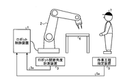
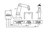
- FIG. 1 is a schematic diagram illustrating an example of a robot system including the robot control device according to the first embodiment and a work site to which the robot system is applied.
- 1 is a block diagram showing an example of the configuration of the robot control apparatus shown in FIG.
- FIG. 3 is a block diagram showing a configuration example of a robot control apparatus according to a second embodiment.
- FIG. 6 is a block diagram showing a configuration example of a robot control apparatus according to the third embodiment.
- the figure which shows the typical bird's-eye view which shows the work site where a robot and an operator share work space in Embodiment 3 and work Schematic diagram showing an example of a robot system including a robot control device according to a fourth embodiment and a work site to which the robot system is applied.
- FIG. 7 is a block diagram showing a configuration example of a robot control apparatus according to a fifth embodiment.
- FIG. 14 is a block diagram illustrating a configuration example of a work area setting unit illustrated in FIG. 14.
- FIG. 7 is a block diagram showing a configuration example of a robot control apparatus according to a sixth embodiment.
- FIG. 1 is a schematic diagram illustrating an example of a robot system including the robot control device 1 according to the first embodiment of the present invention and a work site to which the robot system is applied.
- a robot control device 1 shown in FIG. 1 is connected to a robot 2, and receives a robot joint angle signal 3 a from a robot joint angle measurement device 3 and a work process designation signal 5 a from a work process designation device 5. In response, an operation command is output.
- a work table 6 is arranged in the work site shown in FIG. 1, and a worker 7 exists, and the robot 2 operates while sharing a work space with the worker 7.
- FIG. 2 is a block diagram showing a configuration example of the robot control apparatus 1 shown in FIG.
- the robot control apparatus 1 shown in FIG. 2 includes a robot control state measuring unit 102 that measures robot control state information 102a that is a robot position and posture, and a work operation of the worker 7 from the start to the end of the work process.
- An area including the space occupied by the body of the worker 7 is stored as a work area, and the current work process of the worker 7 is determined based on the work process designation signal 5a that designates the work process currently performed by the worker 7.
- a work area setting unit 104 that sets a corresponding work area and outputs work area information 104a, and a robot command generation unit that generates an operation command 105a for the robot 2 based on the work area information 104a and the robot control state information 102a. 105.
- the robot controller 1 stores the work area data of the worker 7 for each work process of the worker 7 in a storage unit (not shown).
- the work process is a series of work by the worker 7 divided according to the work content.
- the division point of the work process includes a change point of the position of the worker 7, a change point of the position of tools and parts used in the work, a change point of the body part used in the work, and a discontinuous point of the work movement of the worker 7. It can be illustrated.
- the work process may be divided according to the work process table of the worker 7 already used at the work site, or may be divided by setting a required work time for each work process.
- the work process may be set such that the worker 7 does not work, and the work area corresponding to the work process is set as an empty set.
- the robot control device 1 stores in advance, as work area data, a space area occupied by the body part in the work process for one or more divided work processes for which work contents are set in advance. ing.
- This work area data may be created in advance on CAD (Computer Aided Design) assuming the movement range of the worker 7 for each work process, or a worker when the worker 7 actually performs the work process. You may create by measuring previously 7 operation
- CAD Computer Aided Design
- the robot 2 includes a plurality of arms, and each joint, which is a connection point of the arms, includes a driving device that controls a joint angle, and takes various positions and postures according to an operation command from the robot control device 1.
- the driving device include an electric motor represented by a servo motor or a stepping motor, or a cylinder using air pressure or hydraulic pressure, but the driving device is not limited to these.
- the robot system shown in FIG. 1 includes a robot joint angle measuring device 3 that measures the joint angle of the robot 2 at the current time.
- the robot joint angle measuring device 3 can be exemplified by an encoder, and is provided at each joint of each arm of the robot 2.
- the robot joint angle measuring device 3 can be exemplified by an image sensor such as a camera, and each joint angle of the robot 2 may be measured using such an image sensor.
- the work process designation device 5 outputs a work process designation signal 5a for designating a work process currently being executed by the worker 7 from the work process data stored in the robot controller 1.
- the work process designating device 5 can be exemplified by a digital switch, and this digital switch can be switched by the operator 7.
- the digital switch may have buttons arranged so that the number of the divided work processes can be specified, or by setting the execution order in the work process in advance in the work process data, the digital switch Buttons may be arranged to manipulate the execution order.
- the transmission format of the work process designation signal 5a may be wired or wireless. When the transmission format is wireless transmission, the robot control device 1 may be provided with a wireless reception unit.
- the workers differ for each work process in the work environment or the worker's part.
- the work process designating device 5 The work process determination data to be obtained can be acquired, and the work process designation signal 5a may be output based on the measured result and the work process determination data.
- RGB-D (Red Green Blue-Depth) sensors and range sensors can be exemplified as sensors that can acquire work process determination data. Sensors that can acquire work process determination data include It is not limited to these.
- sensors such as a mat switch, a light curtain, and a laser sensor may be used in combination for the purpose of compensating the undetectable area of these sensors and improving the detection accuracy.
- the robot control state measuring unit 102 calculates the angular velocity at each joint of the robot 2 based on the angle information at each joint of the robot 2 included in the robot joint angle signal 3a input from the robot joint angle measuring device 3.
- the angular velocity at each joint can be calculated by taking the time difference value of the corresponding joint angle. Further, noise can be removed by performing filter processing on the time difference value of the angular velocity at each joint.
- a low-pass filter can be exemplified as the filter of the filter processing.
- the robot control device 1 holds the body data of the robot 2, and the robot control state measurement unit 102 determines the robot 2 as the position and posture of the robot 2 based on the joint angle at each joint of the robot 2 and the angular velocity at each joint. It is possible to calculate the control state information 102a.
- the work area setting unit 104 outputs work area information 104a corresponding to the current work process of the worker 7 designated by the work process designation signal 5a from the work area data stored in the robot controller 1.
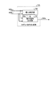
- FIG. 3 is a block diagram showing a configuration example of the robot command generation unit 105 shown in FIG.
- the robot command generation unit 105 shown in FIG. 3 is based on an intrusion determination unit 106 that outputs an intrusion determination signal 106a indicating whether or not the robot 2 has entered the work area of the work area information 104a, and an intrusion determination signal 106a.
- the robot 2 When it is determined that the robot 2 has not entered the work area of the work area information 104a, the robot 2 outputs an operation command 105a to the robot 2 in the non-intrusion control mode that is the first control mode.
- an operation command output unit 107 is provided that outputs an operation command 105a to the robot 2 in the intrusion control mode that is the second control mode. .
- the intrusion determination unit 106 outputs an intrusion determination signal 106a to the work area information 104a of the robot 2 based on the robot control state information 102a and the work area information 104a.
- a part of the housing of the robot 2 represented by the robot hand may be set as a determination point, and it may be determined whether or not the determination point exists in the work area information 104a.
- the motion command 105a is output according to the robot motion trajectory.
- the robot motion trajectory is a command value history of the joint angle of each arm constituting the robot 2, and is previously taught by the work content performed by the robot 2.
- the intrusion determination unit 106 changes the intrusion determination signal 106a to change the second control mode. Transition to control mode. Further, the operation may be controlled so that the robot 2 is stopped before entering the work area so that the robot 2 does not enter the work area of the work area information 104a.
- a stop command is output to the robot 2.
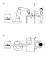
- FIG. 4 is a schematic diagram showing a work site where the robot 2 and the worker 7 share the work space and perform work in the present embodiment.
- 4A shows a side view of the work site
- FIG. 4B shows an overhead view of the work site.
- the robot 2 and the worker 7 perform work in a space on the work table 6 that is a shared work space.
- the robot 2 operates according to a preset robot motion trajectory, and the worker 7 temporarily enters the movable range of the robot 2 at that time.
- the robot 2 and the worker 7 are separated by a safety fence 10, and the worker 7 enters based on a signal from an intrusion detection device 11 such as an interlock or a light curtain. Is detected, the work table 6 is set as a work space for the worker 7, the robot 2 stops operating, and the robot 2 resumes its operation when the intrusion of the worker 7 is no longer detected. And the robot 2 shares a work space.
- an intrusion detection device 11 such as an interlock or a light curtain
- the work area of the worker 7 is set according to the work process of the worker 7, and the operation restriction range for the robot 2 can be narrowed based on the work area. it can. Therefore, the stop frequency of the robot 2 can be suppressed, and as a result, the cooperative work efficiency between the worker 7 and the robot 2 can be improved.
- the work area may be set as described above, and the safety fence 10 and the intrusion detection device 11 may be provided.
- FIG. 5 is a block diagram showing a configuration example of the robot control apparatus 1A according to the present embodiment.
- a robot control apparatus 1A shown in FIG. 5 includes a robot command generation unit 105A instead of the robot command generation unit 105 shown in FIG.
- FIG. 6 is a block diagram illustrating a configuration example of the robot command generation unit 105A illustrated in FIG.
- a robot command generation unit 105A illustrated in FIG. 6 includes a retraction operation trajectory generation unit 108, and includes an operation command output unit 107A instead of the operation command output unit 107 illustrated in FIG.
- the retraction operation trajectory generation unit 108 generates retraction operation trajectory information 108a from a current control state of the robot 2 to a control state at a preset retreat point of the robot 2 based on the robot control state information 102a.
- the retreat point is a space point that temporarily moves separately from the set work so that the robot 2 does not hinder the work of the worker 7, and the work contents of the worker 7 and the preset work One or more spatial points set in consideration of a region.
- the retraction movement trajectory information 108a up to the retraction point may be generated by linear interpolation of the current robot control state information 102a and the amount of change in the joint angle of each arm included in the robot 2 at the retraction point.
- the operation command output unit 107A outputs an operation command 105a to the robot 2 based on the robot control state information 102a, the work area information 104a, the intrusion determination signal 106a, and the retreat operation trajectory information 108a.
- the operation command output unit 107A determines that the robot 2 has not entered the work area of the work area information 104a by the intrusion determination signal 106a
- the operation command output unit 107A uses the non-intrusion control mode that is the first control mode.
- Operation command 105a is output, and when it is determined that the robot 2 has entered the work area of the work area information 104a, the operation command to the robot 2 is executed in the control mode at the time of entry, which is the second control mode. 105a is output.
- the non-intrusion control mode which is the first control mode in the operation command output unit 107A, is the same as that of the operation command output unit 107 in the first embodiment, and a description thereof will be omitted.
- the operation command 105a to the robot 2 is output according to the retreat operation trajectory information 108a.
- the retreat operation trajectory information 108a when a plurality of retreat points are set, one is selected from a plurality of retreat operation trajectory information 108a.
- a retreat point to be used in advance for each work process may be designated.
- a retreat point at which the robot 2 can leave the work area of the work area information 104a in the shortest distance or the shortest time is selected according to the retreat motion trajectory information 108a. May be.
- the retraction point may be selected so that the volume of the housing portion of the robot 2 that has entered the work area is minimized before the robot 2 leaves the work area of the work area information 104a. Alternatively, by the time the robot 2 leaves the work area of the work area information 104a, the robot 2 is retracted so that the volume of a specific part represented by the robot hand of the robot 2 that has entered the work area is minimized. A point may be selected.
- the robot 2 when the robot 2 is operated in the direction of advancing or returning the work in accordance with the robot operation trajectory set in advance, it follows the selection method of the retreat operation trajectory information 108a. As a result of the evaluation, if it is more appropriate to move out of the work area information 104a according to the robot movement trajectory than to move out of the work area of the work area information 104a according to any of the retreat movement trajectory information 108a.
- the operation command 105a to the robot 2 may be output according to the robot operation trajectory.
- the operation command output unit 107A determines that the robot 2 has left the work area of the work area information 104a. 2 may be set to stop before moving to the retreat point.
- FIG. 7 is a diagram showing a schematic overhead view showing a work site where the robot 2 and the worker 7 share a work space and perform work in the present embodiment.
- FIG. 7 is the same as the work site shown in FIG. 4, and the same components are denoted by the same reference numerals and description thereof is omitted.
- the operator 7 enters the shared work space in order to perform the work of assembling the work object 81 to the work object 82.
- the worker 7 is transporting the work object 81 and approaching the work object 82 placed on the work table 6, and the robot 2 moves against the work object 82. Doing work.
- the current work process scheduled route 12 of the worker 7 is indicated by a broken-line arrow.
- the worker 7 is approaching the work object 82 from the state of FIG. 7 (a).
- FIG. 7B when the intrusion detection device 11 detects the intrusion of the worker 7, the robot 2 stops its operation while approaching the work target 82, and the worker 7 stops the work target 82. There is a possibility that it is not possible to secure a work range for performing work on the above.
- the worker 7 cannot perform the assembling work of the work object 81 and the work object 82 because the presence of the robot 2 becomes an obstacle, and the worker 7 waits giving priority to the operation of the robot 2, or There is a problem that it is necessary to forcibly stop the automatic operation of the robot 2 and move the robot 2 to a position where the operation is not hindered by the jog operation.
- the robot 2 when the worker 7 approaches the work object 82, a work area is set, and the robot 2 is output by outputting an operation command 105a so as to retract the robot 2 from the work area. Therefore, the operator 7 and the robot 2 can be prevented from excessively approaching and obstructing the work area. As a result, the waiting operation of the worker 7 and the moving work of the robot 2 by jog operation are unnecessary. The collaborative work efficiency can be improved.
- Embodiment 3 FIG. In the present embodiment, a mode will be described in which the robot operates so as to retreat in advance from the work area next to the worker's current work process.
- FIG. 8 is a block diagram showing a configuration example of the robot control apparatus 1B according to the present embodiment.
- the same components as those shown in FIG. 8 includes a work area setting unit 104B instead of the work area setting unit 104 shown in FIG. 2, and a robot command generation unit 105B instead of the robot command generation unit 105.
- the work area setting unit 104B stores the order of the next work process in addition to the work area in the work process, and stores it in addition to the work area of the work area information 104a corresponding to the work process of the current worker 7.
- the work area of the next work area information 104b corresponding to the next work process is set and output, and the robot command generation unit 105B is based on the work area information 104a, the next work area information 104b, and the robot control state information 102a.
- the robot 2 does not enter the work area of the next work area information 104b but has entered the work area of the work area information 104a.
- the robot 2 has not entered, but has entered the work area of the next work area information 104b, and the robot 2 has entered the work area information 104a and the next work area information 104. By the case not be penetrated in any work area, and to change the method of generating the operation command 105a to the robot 2.
- the operation command 105a is generated by the second control mode in the first embodiment when the robot 2 has not entered the next work area information 104b but has entered the work area of the work area information 104a. Is output when the robot 2 has not entered the work area of the work area information 104a but has entered the work area of the next work area information 104b. Outputs a retract command in the intrusion control mode, which is the second control mode in the second embodiment, to the robot 2, and the robot 2 enters either the work area information 104a or the next work area information 104b. If not, a method of outputting an operation command in the non-intrusion control mode which is the first control mode in the first embodiment can be exemplified.
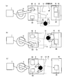
- FIG. 9 is a diagram showing a schematic overhead view showing a work site where the robot 2 and the worker 7 share the work space and perform work in the present embodiment.
- FIG. 9 is the same as the work site shown in FIG. 4, and the same components are denoted by the same reference numerals and description thereof is omitted.
- a work object 82 and a work object 83 are arranged on the work table 6, a work table 61 facing one side of the rectangular work table 6 is installed, and the work object 81 and the work object 81 are arranged on the work table 61.
- a work object 84 is arranged.
- FIG. 9 shows an example of the work site, and the layout of the work site and the work content of the worker 7 are not limited to this.
- FIGS. 9A to 9C show the current work process schedule path 12 corresponding to the current work process, the current work area 14 corresponding to the current work process, and the next work process schedule corresponding to the next work process.
- a path 13 and a next work area 15 corresponding to the next work process are shown.
- the current work area 14 and the next work area 15 are areas set by the user to prohibit the robot 2 from entering when the worker 7 performs a corresponding work.
- the current work area 14 and the next work area 15 are larger than the body occupation area of the worker 7 while the worker 7 performs the target work in consideration of variations in work movements when the worker 7 repeatedly performs the target work. It is preferable to set a wide range. Since the work process is changed in the process from FIG. 9A to FIG. 9C, the next work area 15 in FIG. 9A becomes the current work area 14 in FIG. Is a newly set area. The same applies to the current work area 14 and the next work area 15 in FIGS. 9B and 9C.
- FIGS. 9A to 9C The work processes in FIGS. 9A to 9C are set as follows. First, the robot 2 performs a machining operation on the work object 82 and a machining operation on the work object 83. Next, the operator 7 performs an operation of assembling the work object 81 with the work object 82 which has been processed by the robot 2 to process the work object 85. In parallel with or following the assembly work of the worker 7, the robot 2 performs a machining work on the work object 83. Next, the worker 7 transports the work object 83 that has been processed by the robot 2 to be assembled with the work object 84. Therefore, first, the worker 7 moves from the position shown in FIG.
- the next work process after the work process for acquiring the work object 81 is a work for assembling the acquired work object 81 to the work object 82 toward the work table 6. Therefore, in FIG. 9A, the next work area 15 corresponding to the next work process is set so as to include the work object 81 and the work object 82. At this time, in FIG.
- the retraction command for the intrusion control mode which is the control mode, is output and retreats outside the next work area 15 within a range that does not enter the current work area 14.
- the robot 2 can not be considered in the movement route predicted only from the movement of the worker 7, but for the work area occupied by the future movement of the worker 7 according to the work process,
- the robot 2 can be saved in advance from the next work area of the current work process, and the robot 2 can be prevented from entering the work area of the next work area information 104b of the worker 7.
- the movement path of the worker 7 is predicted only from the current movement flow of the worker 7, if the movement of the worker 7 that cannot be predicted from the current movement flow occurs according to the work process, the movement path is predicted. It becomes difficult. According to the present embodiment, even if an operation that cannot be predicted from the current operation flow occurs, such as a sudden change of the operation direction according to the work process of the worker 7, prediction is possible.
- FIG. 10 is a schematic diagram illustrating an example of a robot system including the robot control apparatus 1C according to the present embodiment and a work site to which the robot system is applied.
- an operator measuring device 4 is added to the robot system shown in FIG.
- FIG. 10 the same components as those shown in FIG.
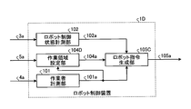
- FIG. 11 is a block diagram showing a configuration example of the robot control apparatus 1C shown in FIG.
- an operator measurement unit 101 is added to the robot control apparatus 1 shown in FIG.
- the worker measurement unit 101 measures the state of the worker 7 that is the worker position and posture, and outputs worker state information 101a.
- the robot command generation unit 105C generates an operation command 105a for the robot 2 based on the worker status information 101a, the work area information 104a, and the robot control status information 102a.
- FIG. 11 the same components as those shown in FIG.
- the worker measurement device 4 is a sensor device that measures one or more body parts of the worker 7 as body measurement points and outputs position information 4a.
- the position information 4a is output to the robot controller 1C at a constant cycle.
- the worker measuring device 4 can be exemplified by an RGB-D sensor and a range sensor, similar to the sensor capable of acquiring work process determination data in the first embodiment, but the worker measuring device 4 Is not limited to these.
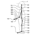
- FIG. 12 is a diagram illustrating an example of the body measurement points of the worker 7 set in the present embodiment.
- the body measurement points of the operator 7 shown in FIG. 12 include a head 701, a neck 702, a shoulder 703, a spine 704, a buttocks 705, a knee 706, an ankle 707, an elbow 708, a wrist 709, and a hand.
- a part 710 and a toe part 711 are set.
- a bone part 721 is set between the head part 701 and the neck part 702, a bone part 722 is set between the neck part 702 and the shoulder part 703, and a bone is set between the shoulder part 703 and the spine part 704.
- a portion 723 is set, a bone portion 724 is set between the spine portion 704 and the heel portion 705, a bone portion 725 is set between the heel portion 705 and the knee portion 706, and between the knee portion 706 and the ankle portion 707
- a bone portion 726 is set between the ankle portion 707 and the toe portion 711, a bone portion 728 is set between the shoulder portion 703 and the elbow portion 708, and the elbow portion 708 and the wrist
- a bone portion 729 is set between the wrist portion 709 and the bone portion 730 between the wrist portion 709 and the hand portion 710.
- the posture of the worker 7 is detected based on the position information 4 a of the body measurement points measured by the worker measuring device 4 by representing the body of the worker 7 with a human skeleton model. Can do.
- the body measurement points are not limited to these, and a part of the body measurement points shown in FIG. 12 may be selected or the body measurement points shown in FIG. Other body measurement points may be added.
- signals from existing sensors such as mat switches, light curtains, and laser sensors installed at general sites are used to improve the accuracy of the position information 4a of the worker 7 and to the worker measuring device 4. You may use together for the purpose of compensation of the area which cannot detect the position of the worker 7.
- FIG. 13 is a block diagram showing a configuration example of the robot command generation unit 105C shown in FIG.
- a robot command generation unit 105C illustrated in FIG. 13 includes an operation command output unit 107C instead of the operation command output unit 107A of the robot command generation unit 105A illustrated in FIG.
- the motion command output unit 107C outputs a motion command 105a to the robot 2 based on the worker status information 101a, the robot control status information 102a, the work area information 104a, the intrusion determination signal 106a, and the retreat motion trajectory information 108a.
- the same components as those shown in FIG. 6 are denoted by the same reference numerals, and the description thereof is omitted. Further, in this embodiment, the retracting motion trajectory generating unit 108 may not be provided.
- the operation command output unit 107C determines that the robot 2 has not entered the work area of the work area information 104a based on the intrusion determination signal 106a, the operation command output unit 107C uses the non-intrusion control mode that is the first control mode.
- the operation command 105a is output to the robot 2 and it is determined that the robot 2 has entered the work area of the work area information 104a, the robot 2 is instructed by the intrusion control mode which is the second control mode. An operation command 105a is output.
- the non-intrusion control mode which is the first control mode in the operation command output unit 107C
- the intrusion time control mode that is the second control mode in the operation command output unit 107C
- a limit value is set for the operation speed of the robot 2.
- the limit value of the operation speed of the robot 2 may be set lower as the distance between the two is closer.
- the limit value of the operation speed of the robot 2 may be set lower as the relative speed is higher.
- the robot control device 1C keeps the current positional relationship between the robot 2 and the worker 7.
- the robot 2 can be retreated out of the work area of the work area information 104a while avoiding the collision between the two.
- FIG. 14 is a block diagram showing a configuration example of the robot control apparatus 1D according to the present embodiment.
- the same components as those shown in FIG. 11 are denoted by the same reference numerals, and the description thereof is omitted.
- a robot control apparatus 1D illustrated in FIG. 14 includes a work area setting unit 104D instead of the work area setting unit 104 of the robot control apparatus 1C illustrated in FIG.
- FIG. 15 is a block diagram showing a configuration example of the work area setting unit 104D shown in FIG.
- the work area setting unit 104D illustrated in FIG. 15 includes a work area storage unit 109, a work area correction unit 110, and a work area output unit 111.
- the work area storage unit 109 stores correction work area data obtained by duplicating the work area data so that the work area data stored in advance can be corrected. From the stored correction work area data, the work area specification signal 5a is used.
- the correction work area information 109a corresponding to the work process of the designated worker 7 is output.
- the work area correction unit 110 statistically compares the correction work area information 109a and the worker state information 101a, so that the correction work area information 109a is used as the range used in the actual work operation of the worker 7.
- the corrected work area information 110a is output by correcting the work area so that the difference between the two is reduced.
- the work area output unit 111 outputs the corrected work area information as work area information 104a.
- the work area storage unit 109 corrects the corresponding correction work area data based on the correction work area information 110a.
- the robot control device 1D corrects the preset work area of the work area information 104a of the worker 7 with the worker state information 101a measured by the actual work operation of the worker 7. . For this reason, it is possible to reset the work area of the work area information 104a in accordance with the motion trajectory or the motion range at the time of work different for each worker.
- FIG. 16 is a block diagram showing a configuration example of the robot control apparatus 1E according to the present embodiment.
- a robot control apparatus 1E illustrated in FIG. 16 includes a robot control state measurement unit 102E instead of the robot control state measurement unit 102 of the robot control apparatus 1 illustrated in FIG.
- An operation command 105a is input to the robot control state measuring unit 102E instead of the robot joint angle signal 3a.
- the robot joint angle measuring device 3 can be removed from the robot system, and the size and cost can be reduced.
- the configuration described in the above embodiment shows an example of the contents of the present invention, and can be combined with another known technique, and can be combined with other configurations without departing from the gist of the present invention. It is also possible to omit or change the part.
Landscapes
- Engineering & Computer Science (AREA)
- Robotics (AREA)
- Mechanical Engineering (AREA)
- Human Computer Interaction (AREA)
- Manipulator (AREA)
Abstract
L'objectif de la présente invention est d'obtenir un dispositif de commande de robot qui réduit le risque de collision survenant entre un travailleur et un robot tout en maintenant une efficacité de travail élevée lorsque le travailleur et le robot travaillent dans un espace de travail partagé. La présente invention comprend : une unité de mesure d'état de commande de robot (102) qui mesure un état de commande de robot qui comprend la position et la posture d'un robot ; une unité de définition de zone de travail (104) qui stocke, pour chaque processus de travail, une zone qui contient l'espace occupé par le corps d'un travailleur dans des actions de travail exécutées par le travailleur du début à la fin du processus de travail, et qui définit une zone de travail correspondant au processus de travail actuel du travailleur sur la base d'un signal de spécification de processus de travail qui spécifie le processus de travail qui est actuellement exécuté par l'opérateur ; et une unité de génération de commande de robot (105) qui génère une commande opérationnelle (105a) pour le robot sur la base de la zone de travail et de l'état de commande de robot. L'unité de génération de commande de robot (105) modifie la commande opérationnelle (105a) pour le robot suivant que le robot se trouve ou non à l'intérieur de la zone de travail.
Priority Applications (4)
| Application Number | Priority Date | Filing Date | Title |
|---|---|---|---|
| US16/097,858 US11045955B2 (en) | 2016-05-26 | 2017-04-28 | Robot control device |
| CN201780031483.3A CN109153134B (zh) | 2016-05-26 | 2017-04-28 | 机器人控制装置 |
| JP2018502444A JP6351900B2 (ja) | 2016-05-26 | 2017-04-28 | ロボット制御装置 |
| DE112017002639.3T DE112017002639T5 (de) | 2016-05-26 | 2017-04-28 | Robotersteuerungsvorrichtung |
Applications Claiming Priority (2)
| Application Number | Priority Date | Filing Date | Title |
|---|---|---|---|
| JP2016105489 | 2016-05-26 | ||
| JP2016-105489 | 2016-05-26 |
Publications (1)
| Publication Number | Publication Date |
|---|---|
| WO2017203937A1 true WO2017203937A1 (fr) | 2017-11-30 |
Family
ID=60411153
Family Applications (1)
| Application Number | Title | Priority Date | Filing Date |
|---|---|---|---|
| PCT/JP2017/017012 Ceased WO2017203937A1 (fr) | 2016-05-26 | 2017-04-28 | Dispositif de commande de robot |
Country Status (5)
| Country | Link |
|---|---|
| US (1) | US11045955B2 (fr) |
| JP (1) | JP6351900B2 (fr) |
| CN (1) | CN109153134B (fr) |
| DE (1) | DE112017002639T5 (fr) |
| WO (1) | WO2017203937A1 (fr) |
Cited By (12)
| Publication number | Priority date | Publication date | Assignee | Title |
|---|---|---|---|---|
| US10099372B2 (en) | 2017-02-07 | 2018-10-16 | Veo Robotics, Inc. | Detecting and classifying workspace regions for safety monitoring |
| JP2018187746A (ja) * | 2017-05-11 | 2018-11-29 | ファナック株式会社 | ロボット制御装置及びロボット制御プログラム |
| JP2019145101A (ja) * | 2018-02-16 | 2019-08-29 | ピルツ ゲーエムベーハー アンド コー.カーゲー | 自律動作マシンから人を防護するシステム |
| JP2020095617A (ja) * | 2018-12-14 | 2020-06-18 | コニカミノルタ株式会社 | 安全管理支援システム、および制御プログラム |
| DE102019219071A1 (de) | 2018-12-19 | 2020-07-16 | Fanuc Corporation | Robotersteuervorrichtung, robotersteuersystem und robotersteuerverfahren |
| JP2020160988A (ja) * | 2019-03-27 | 2020-10-01 | オムロン株式会社 | 報知システム、報知装置 |
| US11518051B2 (en) | 2017-02-07 | 2022-12-06 | Veo Robotics, Inc. | Dynamic, interactive signaling of safety-related conditions in a monitored environment |
| US11541543B2 (en) | 2017-02-07 | 2023-01-03 | Veo Robotics, Inc. | Dynamic, interactive signaling of safety-related conditions in a monitored environment |
| US11820025B2 (en) | 2017-02-07 | 2023-11-21 | Veo Robotics, Inc. | Safe motion planning for machinery operation |
| US12049014B2 (en) | 2018-02-06 | 2024-07-30 | Veo Robotics, Inc. | Workplace monitoring and semantic entity identification for safe machine operation |
| US12097625B2 (en) | 2018-02-06 | 2024-09-24 | Veo Robotics, Inc. | Robot end-effector sensing and identification |
| US12103170B2 (en) | 2017-01-13 | 2024-10-01 | Clara Vu | Dynamic, interactive signaling of safety-related conditions in a monitored environment |
Families Citing this family (9)
| Publication number | Priority date | Publication date | Assignee | Title |
|---|---|---|---|---|
| CN113226674B (zh) * | 2018-12-28 | 2024-05-31 | 京瓷办公信息系统株式会社 | 控制装置 |
| JP7036078B2 (ja) | 2019-03-28 | 2022-03-15 | オムロン株式会社 | 制御システム、制御方法、および制御ユニット |
| JP7384602B2 (ja) * | 2019-09-12 | 2023-11-21 | ファナック株式会社 | ロボット制御装置 |
| US11796984B2 (en) * | 2020-04-27 | 2023-10-24 | Fanuc Corporation | Assembly system |
| JP7707478B2 (ja) * | 2020-05-12 | 2025-07-15 | ソレマルテック エス.エー. | 作業デバイス |
| DE112021005409T5 (de) * | 2020-12-21 | 2023-08-03 | Fanuc Corporation | Sicherheits-sichtvorrichtung und sicherheits-sichtsystem |
| US11738956B2 (en) * | 2021-01-26 | 2023-08-29 | Target Brands, Inc. | Door and light curtain control system for depalletization systems and methods |
| KR102690062B1 (ko) | 2021-12-20 | 2024-07-31 | 네이버 주식회사 | 로봇 친화형 건물, 로봇의 작업 제어 방법 및 시스템 |
| US12350842B2 (en) * | 2022-06-03 | 2025-07-08 | Southwest Research Institute | Collaborative robotic system |
Citations (3)
| Publication number | Priority date | Publication date | Assignee | Title |
|---|---|---|---|---|
| JP2007283450A (ja) * | 2006-04-18 | 2007-11-01 | National Institute Of Advanced Industrial & Technology | 人間ロボット共存作業用安全装置 |
| JP4219870B2 (ja) * | 2004-08-09 | 2009-02-04 | 本田技研工業株式会社 | マン・マシン作業システム |
| JP2010188515A (ja) * | 2009-01-26 | 2010-09-02 | Fanuc Ltd | 人間とロボットとの協調動作領域を有する生産システム |
Family Cites Families (29)
| Publication number | Priority date | Publication date | Assignee | Title |
|---|---|---|---|---|
| JP2004243427A (ja) * | 2003-02-12 | 2004-09-02 | Yaskawa Electric Corp | ロボット制御装置およびロボット制御方法 |
| DE102004041821A1 (de) * | 2004-08-27 | 2006-03-16 | Abb Research Ltd. | Vorrichtung und Verfahren zur Sicherung eines maschinell gesteuerten Handhabungsgerätes |
| CN100556623C (zh) * | 2004-10-19 | 2009-11-04 | 松下电器产业株式会社 | 自动机械装置 |
| DE102007028390A1 (de) * | 2007-06-15 | 2008-12-18 | Abb Research Ltd. | Prozesssteuerung, System und Verfahren zur automatisierten Anpassung von Prozessparametern wenigstens einer Handhabungsvorrichtung |
| JP4243326B2 (ja) * | 2007-06-27 | 2009-03-25 | パナソニック株式会社 | ロボットアームの制御装置及び制御方法、ロボット、及びプログラム |
| JP2010120139A (ja) | 2008-11-21 | 2010-06-03 | New Industry Research Organization | 産業用ロボットの安全制御装置 |
| US8415609B2 (en) * | 2009-01-31 | 2013-04-09 | Keyence Corporation | Safety photoelectric switch |
| JP5260673B2 (ja) | 2009-05-22 | 2013-08-14 | トヨタ自動車東日本株式会社 | 作業支援ロボットシステム |
| CN102292194B (zh) * | 2009-08-21 | 2015-03-04 | 松下电器产业株式会社 | 机器人手臂的控制装置及控制方法、装配机器人、机器人手臂的控制程序及机器人手臂的控制用集成电路 |
| JP4699572B2 (ja) * | 2009-09-28 | 2011-06-15 | パナソニック株式会社 | ロボットアームの制御装置及び制御方法、ロボット、ロボットアームの制御プログラム、及び、ロボットアーム制御用集積電子回路 |
| DE102010063214A1 (de) * | 2010-12-16 | 2012-06-21 | Robert Bosch Gmbh | Sicherungseinrichtung für eine Handhabungsvorrichtung, insbesondere einen Industrieroboter, sowie Verfahren zum Betreiben der Sicherungseinrichtung |
| ITTO20110994A1 (it) * | 2011-10-31 | 2013-05-01 | Comau Spa | Metodo per il controllo di almeno due robot aventi rispettivi spazi di lavoro includenti almeno una regione in comune |
| JP5717033B2 (ja) | 2012-07-19 | 2015-05-13 | トヨタ自動車東日本株式会社 | 作業支援システム |
| EP2890529A2 (fr) * | 2012-08-31 | 2015-07-08 | Rethink Robotics Inc. | Systèmes et procédés pour un fonctionnement sûr de robot |
| DE102012108716A1 (de) * | 2012-09-17 | 2014-03-20 | Klingelnberg Ag | Schleuse zur Bauteilhandhabung in einer Maschine sowie Verfahren zur Handhabung |
| JP5949473B2 (ja) | 2012-11-09 | 2016-07-06 | トヨタ自動車株式会社 | ロボット制御装置、ロボット制御方法、およびロボット |
| JP5549724B2 (ja) * | 2012-11-12 | 2014-07-16 | 株式会社安川電機 | ロボットシステム |
| EP2824522B1 (fr) * | 2013-05-06 | 2017-11-29 | ABB Schweiz AG | Fourniture de sécurité humaine dans des environnements d'automatisation mobile |
| JP6229324B2 (ja) * | 2013-06-14 | 2017-11-15 | セイコーエプソン株式会社 | ロボット、ロボット制御装置およびロボットの制御方法 |
| JP2015000470A (ja) * | 2013-06-18 | 2015-01-05 | トヨタ自動車株式会社 | ロボット制御装置及びロボット制御方法 |
| DE202013105036U1 (de) * | 2013-11-08 | 2015-02-10 | Daimler Ag | Erfassungseinrichtung |
| US9452532B2 (en) * | 2014-01-27 | 2016-09-27 | Panasonic Intellectual Property Management Co., Ltd. | Robot, device and method for controlling robot, and computer-readable non-transitory recording medium |
| JP6397226B2 (ja) * | 2014-06-05 | 2018-09-26 | キヤノン株式会社 | 装置、装置の制御方法およびプログラム |
| EP3017920B1 (fr) * | 2014-11-07 | 2017-08-23 | Comau S.p.A. | Robot industriel et procédé pour commander un tel robot |
| DE102014222857A1 (de) * | 2014-11-10 | 2016-05-12 | Kuka Roboter Gmbh | Flexibles taktzeitoptimiertes Teilen eines Arbeitsraums für Roboter |
| JP6364096B2 (ja) * | 2014-12-26 | 2018-07-25 | 川崎重工業株式会社 | ロボットシステム |
| JP6055002B2 (ja) * | 2015-02-20 | 2016-12-27 | ファナック株式会社 | ロボットを退避動作させる人間協調ロボットシステム |
| US20190105779A1 (en) * | 2016-03-24 | 2019-04-11 | Polygon T.R Ltd. | Systems and methods for human and robot collaboration |
| CN107717982B (zh) * | 2016-08-12 | 2020-09-25 | 财团法人工业技术研究院 | 机械手臂的控制装置及操作方法 |
-
2017
- 2017-04-28 JP JP2018502444A patent/JP6351900B2/ja active Active
- 2017-04-28 DE DE112017002639.3T patent/DE112017002639T5/de not_active Withdrawn
- 2017-04-28 CN CN201780031483.3A patent/CN109153134B/zh active Active
- 2017-04-28 US US16/097,858 patent/US11045955B2/en active Active
- 2017-04-28 WO PCT/JP2017/017012 patent/WO2017203937A1/fr not_active Ceased
Patent Citations (3)
| Publication number | Priority date | Publication date | Assignee | Title |
|---|---|---|---|---|
| JP4219870B2 (ja) * | 2004-08-09 | 2009-02-04 | 本田技研工業株式会社 | マン・マシン作業システム |
| JP2007283450A (ja) * | 2006-04-18 | 2007-11-01 | National Institute Of Advanced Industrial & Technology | 人間ロボット共存作業用安全装置 |
| JP2010188515A (ja) * | 2009-01-26 | 2010-09-02 | Fanuc Ltd | 人間とロボットとの協調動作領域を有する生産システム |
Cited By (25)
| Publication number | Priority date | Publication date | Assignee | Title |
|---|---|---|---|---|
| US12103170B2 (en) | 2017-01-13 | 2024-10-01 | Clara Vu | Dynamic, interactive signaling of safety-related conditions in a monitored environment |
| US10899007B2 (en) | 2017-02-07 | 2021-01-26 | Veo Robotics, Inc. | Ensuring safe operation of industrial machinery |
| US12036683B2 (en) | 2017-02-07 | 2024-07-16 | Veo Robotics, Inc. | Safe motion planning for machinery operation |
| US11623356B2 (en) | 2017-02-07 | 2023-04-11 | Veo Robotics, Inc. | Dynamic, interactive signaling of safety-related conditions in a monitored environment |
| US11541543B2 (en) | 2017-02-07 | 2023-01-03 | Veo Robotics, Inc. | Dynamic, interactive signaling of safety-related conditions in a monitored environment |
| US11518051B2 (en) | 2017-02-07 | 2022-12-06 | Veo Robotics, Inc. | Dynamic, interactive signaling of safety-related conditions in a monitored environment |
| US10099372B2 (en) | 2017-02-07 | 2018-10-16 | Veo Robotics, Inc. | Detecting and classifying workspace regions for safety monitoring |
| US12397434B2 (en) | 2017-02-07 | 2025-08-26 | Symbotic Llc | Safe motion planning for machinery operation |
| US11279039B2 (en) | 2017-02-07 | 2022-03-22 | Veo Robotics, Inc. | Ensuring safe operation of industrial machinery |
| US11040450B2 (en) | 2017-02-07 | 2021-06-22 | Veo Robotics, Inc. | Dynamically determining and monitoring workspace safe zones using semantic representations of workpieces |
| US11820025B2 (en) | 2017-02-07 | 2023-11-21 | Veo Robotics, Inc. | Safe motion planning for machinery operation |
| US10882185B2 (en) | 2017-02-07 | 2021-01-05 | Veo Robotics, Inc. | Dynamically determining workspace safe zones with speed and separation monitoring |
| US11376741B2 (en) | 2017-02-07 | 2022-07-05 | Veo Robotics, Inc. | Dynamically determining workspace safe zones with speed and separation monitoring |
| JP2018187746A (ja) * | 2017-05-11 | 2018-11-29 | ファナック株式会社 | ロボット制御装置及びロボット制御プログラム |
| US10486307B2 (en) | 2017-05-11 | 2019-11-26 | Fanuc Corporation | Robot control device and computer readable medium |
| US12049014B2 (en) | 2018-02-06 | 2024-07-30 | Veo Robotics, Inc. | Workplace monitoring and semantic entity identification for safe machine operation |
| US12097625B2 (en) | 2018-02-06 | 2024-09-24 | Veo Robotics, Inc. | Robot end-effector sensing and identification |
| JP7460324B2 (ja) | 2018-02-16 | 2024-04-02 | ピルツ ゲーエムベーハー アンド コー.カーゲー | 自律動作マシンから人を防護するシステム |
| JP2019145101A (ja) * | 2018-02-16 | 2019-08-29 | ピルツ ゲーエムベーハー アンド コー.カーゲー | 自律動作マシンから人を防護するシステム |
| JP2020095617A (ja) * | 2018-12-14 | 2020-06-18 | コニカミノルタ株式会社 | 安全管理支援システム、および制御プログラム |
| US11345036B2 (en) | 2018-12-19 | 2022-05-31 | Fanuc Corporation | Robot control device, robot control system, and robot control method |
| DE102019219071A1 (de) | 2018-12-19 | 2020-07-16 | Fanuc Corporation | Robotersteuervorrichtung, robotersteuersystem und robotersteuerverfahren |
| JP7127592B2 (ja) | 2019-03-27 | 2022-08-30 | オムロン株式会社 | 報知システム |
| US11967183B2 (en) | 2019-03-27 | 2024-04-23 | Omron Corporation | Notification system and notification device |
| JP2020160988A (ja) * | 2019-03-27 | 2020-10-01 | オムロン株式会社 | 報知システム、報知装置 |
Also Published As
| Publication number | Publication date |
|---|---|
| JP6351900B2 (ja) | 2018-07-04 |
| US20190134819A1 (en) | 2019-05-09 |
| CN109153134A (zh) | 2019-01-04 |
| CN109153134B (zh) | 2021-08-13 |
| JPWO2017203937A1 (ja) | 2018-06-07 |
| US11045955B2 (en) | 2021-06-29 |
| DE112017002639T5 (de) | 2019-03-28 |
Similar Documents
| Publication | Publication Date | Title |
|---|---|---|
| JP6351900B2 (ja) | ロボット制御装置 | |
| EP2660014B1 (fr) | Dispositif de commande et procédé d'apprentissage pour robot à articulations multiples à sept arbres | |
| JP5668770B2 (ja) | ロボットシステム、及び、ロボットシステムの制御方法 | |
| CN108568815B (zh) | 机器人系统和机器人控制方法 | |
| US11039895B2 (en) | Industrial remote control robot system | |
| US10427298B2 (en) | Robot system displaying information for teaching robot | |
| JP4167940B2 (ja) | ロボットシステム | |
| JP4291385B2 (ja) | ロボット手先部の速度に基づいてロボットを停止させるロボット制御装置 | |
| US20060149421A1 (en) | Robot controller | |
| CN110948468B (zh) | 机器人的控制方法和控制装置 | |
| EP2781315A1 (fr) | Système de prélèvement par robot, dispositif de commande et procédé de fabrication d'une pièce à usiner | |
| JP6729773B2 (ja) | ロボット制御装置およびこれを用いたロボットシステム | |
| JP2010120139A (ja) | 産業用ロボットの安全制御装置 | |
| US20120239190A1 (en) | Robot and Method For Operating A Robot | |
| JP5228783B2 (ja) | ロボットの原点復帰装置 | |
| JP2019107704A (ja) | ロボットシステム及びロボット制御方法 | |
| CN110856932A (zh) | 干涉回避装置以及机器人系统 | |
| US11034022B2 (en) | Robot teaching system, controller and hand guide unit | |
| JP2014065100A (ja) | ロボットシステム、及びロボットのティーチング方法 | |
| JP2019198907A (ja) | ロボットシステム | |
| JPH07271415A (ja) | 協調ロボット制御方法 | |
| JP2016196069A (ja) | 産業用ロボットの回避軌道生成装置および回避軌道生成方法 | |
| CN107735226B (zh) | 利用机器人驶过预设的轨迹 | |
| JP2009148850A (ja) | ロボットの動作制御装置及びその動作制御方法 | |
| JP2022141028A (ja) | 制御装置、制御システム、制御方法及びプログラム |
Legal Events
| Date | Code | Title | Description |
|---|---|---|---|
| ENP | Entry into the national phase |
Ref document number: 2018502444 Country of ref document: JP Kind code of ref document: A |
|
| 121 | Ep: the epo has been informed by wipo that ep was designated in this application |
Ref document number: 17802534 Country of ref document: EP Kind code of ref document: A1 |
|
| 122 | Ep: pct application non-entry in european phase |
Ref document number: 17802534 Country of ref document: EP Kind code of ref document: A1 |