WO2017204005A1 - Dispositif de détection d'anomalies et dispositif de notification - Google Patents
Dispositif de détection d'anomalies et dispositif de notification Download PDFInfo
- Publication number
- WO2017204005A1 WO2017204005A1 PCT/JP2017/018001 JP2017018001W WO2017204005A1 WO 2017204005 A1 WO2017204005 A1 WO 2017204005A1 JP 2017018001 W JP2017018001 W JP 2017018001W WO 2017204005 A1 WO2017204005 A1 WO 2017204005A1
- Authority
- WO
- WIPO (PCT)
- Prior art keywords
- light
- abnormality
- sensor
- detected
- illuminance
- Prior art date
- Legal status (The legal status is an assumption and is not a legal conclusion. Google has not performed a legal analysis and makes no representation as to the accuracy of the status listed.)
- Ceased
Links
Images


Classifications
-
- B—PERFORMING OPERATIONS; TRANSPORTING
- B60—VEHICLES IN GENERAL
- B60Q—ARRANGEMENT OF SIGNALLING OR LIGHTING DEVICES, THE MOUNTING OR SUPPORTING THEREOF OR CIRCUITS THEREFOR, FOR VEHICLES IN GENERAL
- B60Q11/00—Arrangement of monitoring devices for devices provided for in groups B60Q1/00 - B60Q9/00
- B60Q11/005—Arrangement of monitoring devices for devices provided for in groups B60Q1/00 - B60Q9/00 for lighting devices, e.g. indicating if lamps are burning or not
-
- B—PERFORMING OPERATIONS; TRANSPORTING
- B60—VEHICLES IN GENERAL
- B60Q—ARRANGEMENT OF SIGNALLING OR LIGHTING DEVICES, THE MOUNTING OR SUPPORTING THEREOF OR CIRCUITS THEREFOR, FOR VEHICLES IN GENERAL
- B60Q1/00—Arrangement of optical signalling or lighting devices, the mounting or supporting thereof or circuits therefor
- B60Q1/02—Arrangement of optical signalling or lighting devices, the mounting or supporting thereof or circuits therefor the devices being primarily intended to illuminate the way ahead or to illuminate other areas of way or environments
- B60Q1/04—Arrangement of optical signalling or lighting devices, the mounting or supporting thereof or circuits therefor the devices being primarily intended to illuminate the way ahead or to illuminate other areas of way or environments the devices being headlights
-
- B—PERFORMING OPERATIONS; TRANSPORTING
- B60—VEHICLES IN GENERAL
- B60Q—ARRANGEMENT OF SIGNALLING OR LIGHTING DEVICES, THE MOUNTING OR SUPPORTING THEREOF OR CIRCUITS THEREFOR, FOR VEHICLES IN GENERAL
- B60Q11/00—Arrangement of monitoring devices for devices provided for in groups B60Q1/00 - B60Q9/00
-
- H—ELECTRICITY
- H05—ELECTRIC TECHNIQUES NOT OTHERWISE PROVIDED FOR
- H05B—ELECTRIC HEATING; ELECTRIC LIGHT SOURCES NOT OTHERWISE PROVIDED FOR; CIRCUIT ARRANGEMENTS FOR ELECTRIC LIGHT SOURCES, IN GENERAL
- H05B45/00—Circuit arrangements for operating light-emitting diodes [LED]
- H05B45/50—Circuit arrangements for operating light-emitting diodes [LED] responsive to malfunctions or undesirable behaviour of LEDs; responsive to LED life; Protective circuits
- H05B45/58—Circuit arrangements for operating light-emitting diodes [LED] responsive to malfunctions or undesirable behaviour of LEDs; responsive to LED life; Protective circuits involving end of life detection of LEDs
-
- H—ELECTRICITY
- H05—ELECTRIC TECHNIQUES NOT OTHERWISE PROVIDED FOR
- H05B—ELECTRIC HEATING; ELECTRIC LIGHT SOURCES NOT OTHERWISE PROVIDED FOR; CIRCUIT ARRANGEMENTS FOR ELECTRIC LIGHT SOURCES, IN GENERAL
- H05B47/00—Circuit arrangements for operating light sources in general, i.e. where the type of light source is not relevant
- H05B47/20—Responsive to malfunctions or to light source life; for protection
-
- Y—GENERAL TAGGING OF NEW TECHNOLOGICAL DEVELOPMENTS; GENERAL TAGGING OF CROSS-SECTIONAL TECHNOLOGIES SPANNING OVER SEVERAL SECTIONS OF THE IPC; TECHNICAL SUBJECTS COVERED BY FORMER USPC CROSS-REFERENCE ART COLLECTIONS [XRACs] AND DIGESTS
- Y02—TECHNOLOGIES OR APPLICATIONS FOR MITIGATION OR ADAPTATION AGAINST CLIMATE CHANGE
- Y02B—CLIMATE CHANGE MITIGATION TECHNOLOGIES RELATED TO BUILDINGS, e.g. HOUSING, HOUSE APPLIANCES OR RELATED END-USER APPLICATIONS
- Y02B20/00—Energy efficient lighting technologies, e.g. halogen lamps or gas discharge lamps
- Y02B20/40—Control techniques providing energy savings, e.g. smart controller or presence detection
Definitions
- the present invention relates to an abnormality detection device and a notification device, and more particularly to an abnormality detection device and a notification device that detect a light abnormality.
- Patent Document 1 discloses a monitoring system that detects an abnormality in LED (Light Emitting Diode) illumination.
- the monitoring system includes a camera and LED lighting. According to this monitoring system, it is possible to detect an abnormality in the LED illumination by recognizing the luminance of the specific character pattern photographed by the camera when the LED illumination is emitted.
- the present invention has been made to solve such a problem, and an object of the present invention is to provide an abnormality detection device and a notification device capable of detecting an abnormality of a light regardless of a time zone and surrounding environment. Is to provide.
- An abnormality detection device detects a light abnormality.
- the abnormality detection device includes a sensor, a memory, and a control unit.
- the sensor detects a physical quantity related to the light.
- the memory stores a reference for detecting a light abnormality.
- the control unit detects an abnormality of the light based on the difference between the physical quantity detected by the sensor while the light is turned on and the physical quantity detected by the sensor while the light is turned off, and the reference.
- the sensor continuously detects the physical quantity while the light is on.
- the control unit detects an abnormality of the light based on a difference between the physical quantity detected by the sensor at the start of lighting of the light and the physical quantity continuously detected by the sensor during the lighting of the light.
- the control unit determines that a difference between a physical quantity detected by the sensor at the start of lighting of the light and a physical quantity continuously detected by the sensor during lighting of the light has a first predetermined value. Detects an abnormal light when it exceeds
- this abnormality detection device when the difference between the physical quantity detected by the sensor at the start of lighting of the light and the physical quantity continuously detected by the sensor during lighting of the light exceeds the first predetermined value even once. A light abnormality is detected. Therefore, according to this abnormality detection device, it is possible to detect a light abnormality when there is any doubt about a light abnormality.
- the control unit determines that a difference between a physical quantity detected by the sensor at the start of lighting of the light and a physical quantity continuously detected by the sensor during lighting of the light has a first predetermined value. A light abnormality is detected when the frequency exceeds the predetermined frequency.
- this abnormality detection device if the difference between the physical quantity detected by the sensor at the start of lighting of the light and the physical quantity continuously detected by the sensor during lighting of the light exceeds the first predetermined value once, the light is detected. Is not detected and the light abnormality is detected only when the frequency exceeds a predetermined frequency. Therefore, according to this abnormality detection device, it is possible to detect an abnormality in the light after the possibility that an abnormality has occurred in the light is increased.
- the sensor is an illuminance sensor, and the physical quantity is illuminance.
- the sensor is a color sensor, and the physical quantity is color information.
- An abnormality detection device detects a light abnormality.
- the abnormality detection device includes an illuminance sensor, a color sensor, and a control unit.
- the illuminance sensor detects the illuminance of the light.
- the color sensor detects the illuminance and color information of the light.
- the control unit detects a light abnormality based on the illuminance detected by the illuminance sensor or the color information detected by the color sensor. Then, the control unit determines that the illuminance sensor or the color sensor is abnormal when the difference between the illuminance detected by the illuminance sensor and the illuminance detected by the color sensor exceeds a second predetermined value.
- the abnormality of the light cannot be accurately detected if an abnormality occurs in the illuminance sensor or the color sensor. If the illuminance sensor and the color sensor are normal, the illuminance detected by the illuminance sensor and the illuminance detected by the color sensor should be substantially the same. In this abnormality detection device, it is determined that the illuminance sensor or the color sensor is abnormal when the difference between the illuminance detected by the illuminance sensor and the illuminance detected by the color sensor exceeds a second predetermined value. . Therefore, according to this abnormality detection device, an abnormality of the illuminance sensor or the color sensor can be detected, and as a result, an abnormality of the light can be accurately detected.
- an abnormality detection device and a notification device that can detect an abnormality of a light regardless of the time zone and the surrounding environment.
- FIG. 1 is an overall configuration diagram of an abnormality detection system to which an abnormality detection apparatus according to Embodiment 1 is applied. It is a flowchart which shows the process sequence of abnormality detection of light. It is a figure which shows the change of the illumination intensity by a light lighting continuously. It is a figure which shows another example of the illumination intensity change in case abnormality of a light is detected. It is a flowchart which shows the alerting
- reporting part. 10 is a flowchart illustrating a processing procedure for detecting an abnormality of a light in a modification of the first embodiment. It is a whole block diagram of the abnormality detection system to which the abnormality detection apparatus according to Embodiment 2 is applied.
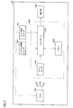
- FIG. 1 is an overall configuration diagram of an abnormality notification system to which an abnormality detection device according to the first embodiment is applied.
- abnormality notification system 10 includes an abnormality detection device 100, a light 200, a notification unit 300, a system activation switch 350, and a light lighting switch 360.
- an abnormality of the light 200 is detected by the abnormality detection device 100.
- the abnormality detection device 100 controls the notification unit 300 so as to notify the user to replace or repair the light 200.
- the user can recognize the necessity of replacement or repair of the light 200 before the failure of the light 200.
- the light 200 is a light source that emits light when receiving power from a power source (not shown).
- the light 200 is, for example, LED lighting or a vehicle headlight.
- the notification unit 300 performs notification for prompting the user to replace or repair the light 200.
- the notification unit 300 receives the instruction from the abnormality detection device 100 and performs the above notification.
- the notification unit 300 is, for example, a display or a speaker.
- a screen prompting the user to replace or repair the light 200 is displayed on the display when the light 200 is abnormal.
- the system start switch 350 is a switch for starting or stopping the abnormality notification system 10.
- the user can start or stop the abnormality notification system 10 by operating the system start switch 350.
- the system activation switch 350 may be, for example, a push type switch or a slide type switch.
- the system activation switch 350 may be a vehicle start switch or an ignition key.
- the light lighting switch 360 is a switch for turning on or off the light 200. The user can turn on or off the light 200 by operating the light lighting switch 360.
- the light lighting switch 360 may be, for example, a push-type switch or a slide-type switch.
- the abnormality detection device 100 includes an illuminance sensor 110, a memory 120, and a controller 130.
- the illuminance sensor 110 detects the illuminance of the light 200 (an example of a physical quantity related to the light 200).
- the illuminance sensor 110 is disposed at a position where the light from the light 200 can be received.
- the memory 120 stores a reference illuminance (an example of a reference amount) serving as a reference for detecting an abnormality of the light 200.
- the reference illuminance will be described in detail later.
- the memory 120 is a non-volatile memory such as a flash memory, for example.
- the controller 130 detects an abnormality of the light 200 based on the illuminance of the light 200 detected by the illuminance sensor 110 and the reference illuminance stored in the memory 120. A method for detecting the abnormality of the light 200 by the controller 130 will be described in detail later.
- the illuminance sensor 110 receives not only light emitted from the light 200 but also external light such as sunlight. Therefore, the illuminance detected by the illuminance sensor 110 is the illuminance due to the light of the light 200 and external light. If the abnormality detection of the light 200 is always performed in the situation where the brightness of the external light is almost the same, the abnormality of the light 200 can be detected by simply monitoring the illuminance detected by the illuminance sensor 110. .
- the abnormality detection of the light 200 is not necessarily performed in a situation where the brightness of the external light is the same. Depending on the time of day and the surrounding environment, the influence of external light may be large. In this case, the abnormality of the light 200 cannot be detected simply by monitoring the illuminance detected by the illuminance sensor 110.
- the controller 130 determines the difference between the illuminance detected by the illuminance sensor 110 while the light 200 is turned on and the illuminance detected by the illuminance sensor 110 while the light 200 is turned off. And an abnormality of the light 200 is detected based on the reference illuminance. More specifically, the controller 130 determines that the difference between the illuminance detected by the illuminance sensor 110 while the light 200 is turned on and the illuminance detected by the illuminance sensor 110 while the light 200 is turned off falls below the reference illuminance. An abnormality of the light 200 is detected.
- the reference illuminance for example, a value of 80% of the illuminance when the light 200 is new (no influence of outside light) is set.
- the difference between the illuminance detected by the illuminance sensor 110 while the light 200 is turned on and the illuminance detected by the illuminance sensor 110 while the light 200 is turned off is based on the illuminance detected by the illuminance sensor 110 while the light 200 is turned on.
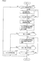
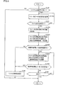
- FIG. 2 is a flowchart showing a processing procedure for detecting an abnormality of the light 200. Referring to FIG. 2, the processing shown by this flowchart is repeatedly executed by being called from a main routine (not shown) in controller 130 during operation of abnormality notification system 10.
- the controller 130 determines whether or not an activation instruction for the abnormality notification system 10 has been received from the user through the system activation switch 350 (step S100).
- indication of the abnormality notification system 10 among the controllers 130 is operate
- step S100 If it is determined that the activation instruction for the abnormality notification system 10 has not been received (NO in step S100), the process returns to the main routine. On the other hand, when it is determined that the activation instruction for abnormality notification system 10 has been received (YES in step S100), controller 130 stores in memory 120 sensor data (illuminance information) detected by illuminance sensor 110 while light 200 is turned off. (Step S110). As described above, this sensor data is used to remove the influence of light other than the light 200 included in the sensor data of the illuminance sensor 110 when the light 200 is lit.
- step S120 determines whether or not an instruction to turn on the light 200 is received from the user through the light turn-on switch 360. If it is determined that an instruction to turn on light 200 has not been received (NO in step S120), the process again proceeds to step S110, and controller 130 updates sensor data during turn-off of light 200 stored in memory 120. .
- controller 130 stores, in memory 120, the illuminance information detected by illuminance sensor 110 at the start of lighting of light 200 (immediately after lighting of light 200).
- step S130 the timing at which the illuminance information is stored in the memory (at the start of lighting of the light 200) is not necessarily immediately after the lighting of the light 200, and may be, for example, after a lapse of a predetermined time from the start of lighting of the light 200.
- the controller 130 accesses the memory 120 to calculate a difference D1 between the illuminance detected by the illuminance sensor 110 when the light 200 starts lighting and the illuminance detected by the illuminance sensor 110 while the light 200 is turned off (Ste S140). Specifically, the controller 130 performs a calculation of subtracting the illuminance while the light 200 is turned off from the illuminance when the light 200 is turned on.
- the difference D1 corresponds to a value obtained by removing the influence of light other than the light 200 from the sensor data of the illuminance sensor 110 when the light 200 is lit.
- the controller 130 determines whether or not the difference D1 is below the reference amount (reference illuminance) stored in the memory 120 (step S150).
- the reference illuminance is, for example, a value that is 80% of the illuminance when the light 200 is new (no influence from outside light). That is, in step S150, it is determined whether the illuminance of the light 200 has decreased by a predetermined value or more since the new time.
- the controller 130 If it is determined that the calculated difference D1 is less than the reference illuminance (YES in step S150), the controller 130 detects an abnormality of the light 200 because there is a high possibility that the failure time of the light 200 is approaching. Then, the abnormality detection signal is output to the notification unit 300 (step S190). Processing in the notification unit 300 after receiving the abnormality detection signal will be described in detail later.
- step S150 if it is determined that the calculated difference D1 is greater than or equal to the reference illuminance (NO in step S150), there is a high possibility that no abnormality has occurred in the light 200 at least immediately after the light 200 is turned on. In this case, the controller 130 performs steps S160 to S180 until the light 200 is extinguished so that the abnormality can be detected even when an abnormality occurs in the light 200 during the subsequent continuous lighting. Repeatedly.
- the controller 130 first calculates a difference D2 (absolute value) between the illuminance detected by the illuminance sensor 110 at the start of lighting of the light 200 and the illuminance currently detected by the illuminance sensor 110 (step S160). Specifically, the controller 130 calculates the absolute value of the difference between the illuminance at the start of lighting the light 200 and the current illuminance. Thereafter, the controller 130 determines whether or not the difference D2 calculated in step S160 exceeds a first predetermined value (step S170). The purpose of the processing in steps S160 and S170 will be described next.
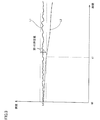
- FIG. 3 is a diagram showing a change in illuminance due to the light 200 being continuously turned on.
- the horizontal axis represents time
- the vertical axis represents the illuminance of the light 200.
- An illuminance change L1 indicated by a solid line indicates an illuminance change when the light 200 is normal.
- the illuminance change L2 indicated by the one-dot chain line indicates the illuminance change when an abnormality is detected while the light 200 is turned on.
- time t0 which is the start of lighting of the light 200
- the illuminance of the light 200 is lu1 for both L1 and L2.
- the illuminance of the light 200 varies slightly due to noise.
- the fluctuation amount of the illuminance of the light 200 from the start of lighting exceeds the first predetermined value, the fluctuation of the illuminance cannot be said to be merely an influence of noise. Detected.
- the first predetermined value a value is set in advance so that fluctuations in illuminance due to noise are not erroneously detected as abnormalities in the light 200.
- Information indicating the first predetermined value is stored in the memory 120, for example.
- the difference D2 between the illuminance indicated by the illuminance change L2 and the illuminance (lu1) at the start of lighting exceeds the first predetermined value. Thereby, the abnormality of the light 200 is detected. That is, according to the abnormality detection apparatus 100, it is possible to detect an abnormality of the light 200 only by monitoring a change in illuminance while the light 200 is lit.
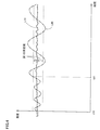
- FIG. 4 is a diagram illustrating another example of a change in illuminance when an abnormality of the light 200 is detected.
- the horizontal axis indicates time
- the vertical axis indicates the illuminance of light 200.
- An illuminance change L10 indicated by a solid line indicates an illuminance change when the light 200 is normal.
- the illuminance change L20 indicated by the alternate long and short dash line indicates the illuminance change when an abnormality is detected while the light 200 is turned on.
- the amplitude of the illuminance change L20 changes greatly compared to the illuminance change L10.
- the illuminance of the light 200 is lu10 for both L10 and L20.
- the difference D2 between the illuminance indicated by the illuminance change L20 and the illuminance at the start of lighting (lu10) exceeds the first predetermined value. Accordingly, an abnormality of the light 200 is detected at the time t11.
- step S170 if it is determined that difference D2 (calculated in step S160) exceeds the first predetermined value (YES in step S170), the failure time of light 200 may be approaching. Since the property is high, the controller 130 detects an abnormality of the light 200 and outputs an abnormality detection signal to the notification unit 300 (step S190).
- step S180 determines whether or not the light 200 is turned off. If it is determined that light 200 is not turned off (NO in step S180), the process proceeds to step S160 again. On the other hand, if it is determined that light 200 has been turned off (YES in step S180), the process returns to the main routine.
- the controller 130 causes the illuminance sensor 110 to detect the illuminance (an example of a physical quantity) detected by the illuminance sensor 110 while the light 200 is turned on and the light 200 is turned off.
- the difference D1 from the detected illuminance falls below the reference illuminance (an example of the reference)
- an abnormality of the light 200 is detected.
- the abnormality of the light 200 can be detected regardless of the time zone and the surrounding environment.
- the controller 130 continuously detects the illuminance (an example of a physical quantity) detected by the illuminance sensor 110 at the start of lighting of the light 200 and the illuminance sensor 110 during the lighting of the light 200.
- An abnormality of the light 200 is detected based on the difference D2 from the detected illuminance. According to this abnormality detection device 100, it is possible to detect an abnormality of the light 200 only by monitoring a change in illuminance while the light 200 is lit.
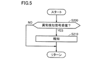
- FIG. 5 is a flowchart showing a notification processing procedure of the notification unit 300.
- the processing shown in this flowchart is performed by main unit (not shown) in notification unit 300 (for example, the controller included in the display when notification unit 300 is a display) during operation of abnormality notification system 10. Called from the routine and executed repeatedly.
- reporting part 300 determines whether the abnormality detection signal was received from the controller 130 (step S200). If it is determined that an abnormality detection signal has not been received (NO in step S200), the process returns to the main routine. On the other hand, when it is determined that the abnormality detection signal has been received (YES in step S200), notification unit 300 performs notification for prompting the user to replace or repair the light 200 (step S210). For example, when the notification unit 300 is a display, the display displays a screen that prompts the user to replace or repair the light 200. Thereafter, the process returns to the main routine.
- the data from which the influence of external light has been removed is used for abnormality detection of the light 200, so the abnormality detection device 100 can be used in the time zone and the surrounding environment. Regardless, it is possible to detect an abnormality of the light 200 and appropriately prompt the user to replace or repair the light 200.
- an abnormality of the light 200 is detected when the difference between the illuminance at the start of lighting of the light 200 and the current illuminance exceeds the first predetermined value even once.
- the abnormality notification system 10 according to the first embodiment, the abnormality of the light 200 can be detected when there is any doubt about the abnormality of the light 200.
- an abnormality of the light 200 is not detected only when the difference between the illuminance at the start of lighting of the light 200 and the current illuminance once exceeds the first predetermined value, and the difference is the first difference.
- the frequency exceeding the predetermined value exceeds the predetermined frequency
- the abnormality of the light 200 is detected.
- the possibility that an abnormality has occurred in the light 200 is increased. Can be detected. Also, erroneous detection due to noise or the like can be prevented.
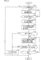
- FIG. 6 is a flowchart showing a processing procedure for detecting an abnormality of the light 200 in the modification of the first embodiment. Referring to FIG. 6, this flowchart is obtained by adding step S175 to the flowchart of FIG. Here, differences from the first embodiment will be mainly described. Note that the processing of the flowchart shown in FIG. 6 is repeatedly executed by being called from a main routine (not shown) in the controller 130 during the operation of the abnormality notification system 10.
- step S170 when it is determined that the difference D2 between the illuminance detected by the illuminance sensor 110 at the start of lighting of the light 200 and the illuminance currently detected by the illuminance sensor 110 exceeds the first predetermined value (YES in step S170). ), The controller 130 determines whether or not the frequency at which the difference D2 exceeds the first predetermined value is equal to or higher than the predetermined frequency (step S175). For example, the controller 130 determines whether or not the number of times that the difference D2 exceeds the first predetermined value in the most recent several cycles is equal to or greater than the predetermined number.
- step S175 If it is determined that the frequency at which the difference D2 exceeds the first predetermined value is greater than or equal to the predetermined frequency (YES in step S175), the controller 130 detects an abnormality of the light 200 and outputs an abnormality detection signal to the notification unit 300. (Step S190). On the other hand, when it is determined that the frequency at which difference D2 exceeds the first predetermined value is less than the predetermined frequency (NO in step S175), the process proceeds to step S180.
- the abnormality of the light 200 is not detected only once the difference D2 exceeds the first predetermined value, and the frequency at which the difference D2 exceeds the first predetermined value is equal to or higher than the predetermined frequency. Only when this happens, the abnormality of the light 200 is detected. Therefore, according to the abnormality detection device 100 according to this modification, it is possible to detect an abnormality of the light 200 after the possibility that an abnormality has occurred in the light 200 is increased.
- Embodiment 2 In Embodiment 1, the example which uses the illumination intensity detected by the illumination intensity sensor 110 as a physical quantity was demonstrated. In the second embodiment, an example will be described in which abnormality of the light 200 is detected using color information detected by the color sensor 110A as a physical quantity.
- FIG. 7 is an overall configuration diagram of an abnormality detection system to which the abnormality detection device according to the second embodiment is applied.
- abnormality notification system 10 ⁇ / b> A includes abnormality detection device 100 ⁇ / b> A instead of abnormality detection device 100 in the first embodiment.
- Other configurations are the same as those in the first embodiment.
- the abnormality detection device 100A detects an abnormality of the light 200.
- the abnormality detection device 100A includes a color sensor 110A, a memory 120A, and a controller 130A.
- the color sensor 110A detects color information (an example of a physical quantity related to the light 200) of light emitted from the light 200.
- the color sensor 110A can also detect the illuminance of the light 200.
- the color information detected by the color sensor 110A is expressed using coordinate information in the L * a * b * color system, for example.
- the color sensor 110A is disposed at a position where the light 200 can be received.
- the memory 120A stores a reference distance (an example of a reference) that serves as a reference for detecting an abnormality of the light 200.
- a reference distance an example of a reference
- the reference distance includes, for example, the coordinates when the new light 200 is turned on and the coordinates when the new light 200 is turned off.
- a value of 80% of the distance (color difference) is set. This reference distance is used to remove the influence of light other than the light 200A from the sensor data of the color sensor 110A, similarly to the reference illuminance in the first embodiment.
- the memory 120A is a non-volatile memory such as a flash memory, for example.
- the controller 130A detects an abnormality of the light 200 based on the color information of the light 200 detected by the color sensor 110A and the reference distance stored in the memory 120A.
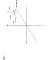
- FIG. 8 is a diagram showing a coordinate space of the L * a * b * color system.
- the L * axis indicates lightness
- the a * axis and b * axis indicate chromaticity (hue and saturation).
- the coordinate C_OFF is an example of coordinates indicated by color information detected by the color sensor 110A while the light 200 is turned off.
- the coordinate C_ON1 is an example of coordinates indicated by color information detected by the color sensor 110A at the start of lighting of the light 200 (immediately after lighting).
- the coordinates C_ON2 and C_ON3 are an example of coordinates indicated by color information detected by the color sensor 110A during continuous lighting of the light 200.
- the coordinates (C_ON1) indicated by the color information detected by the color sensor 110A at the start of lighting of the light 200, and the light 200 being turned off A distance ⁇ from the coordinate (C_OFF) indicated by the color information detected by the color sensor 110A is calculated.
- This distance ⁇ is, for example, the absolute difference between the vector indicated by the color information detected by the color sensor 110A when the light 200 starts to turn on and the vector indicated by the color information detected by the color sensor 110A while the light 200 is turned off. It can also be called a value.
- the calculated distance ⁇ corresponds to a value obtained by removing the influence of light other than the light 200 from the sensor data of the color sensor 110 ⁇ / b> A during lighting of the light 200.
- the abnormality of the light 200 is detected when the calculated distance ⁇ does not fall within the reference range (reference distance ⁇ ⁇ ). That is, in the second embodiment, when the color of light emitted by the light 200 at the start of lighting of the light 200 changes by a predetermined value or more from the new time, an abnormality of the light 200 is detected.
- the influence of light other than the light 200 can be reduced with respect to the abnormality detection of the light 200, so regardless of the time zone and the surrounding environment.
- the abnormality of the light 200 can be detected.
- the coordinates (C_ON2 or C_ON3) indicated by the color information detected by the color sensor 110A while the light 200 is turned on are the color information detected by the color sensor 110A when the light 200 starts to light. It is determined whether or not the object exists in a sphere having a radius r1 centered on the indicated coordinate (C_ON1). That is, in abnormality detection device 100A, it is determined whether the color of light at the start of lighting of light 200 and the current color of light have a predetermined similarity. This is because abnormality detection is performed even when an abnormality occurs in the light 200 during continuous lighting of the light 200.
- the coordinates indicated by the color information of the light 200 slightly fluctuate due to noise, like the illuminance of the light 200 in the first embodiment.
- the coordinates (C_ON1) indicated by the color information detected by the color sensor 110A at the start of lighting of the light 200, and the coordinates (C_ON2 or C_ON3) indicated by the color information currently detected by the color sensor 110A When the distance (distance r) exceeds the first predetermined value (distance r1) (when the distance r does not exist in the sphere having the radius r1), the change in coordinates cannot be said to be merely an influence of noise. An abnormality of the light 200 is detected.
- the first predetermined value is determined in advance such that a change in coordinates due to noise is not erroneously detected as an abnormality of the light 200.
- Information indicating the first predetermined value is stored in advance in memory 120A, for example.
- the first predetermined value is different from the first predetermined value in the first embodiment.
- the distance between the coordinate C_ON1 and the coordinate C_ON2 is smaller than the first predetermined value (distance r1), and thus the abnormality of the light 200 Is not detected.
- the coordinate indicated by the color information currently detected by the color sensor 110A is C_ON3
- the distance between the coordinate C_ON1 and the coordinate C_ON3 exceeds the first predetermined value (distance r1), and thus the abnormality of the light 200 is detected. Detected. That is, according to the abnormality detection device 100A, the abnormality of the light 200 can be detected only by monitoring the change of the color information while the light 200 is lit.
- FIG. 9 is a flowchart showing a processing procedure for detecting an abnormality of the light 200 in the second embodiment.
- this flowchart is common to the flowchart shown in FIG. 2 in some steps.
- steps S110A and S130A to S170A are executed in place of steps S110 and S130 to S170 of FIG. 2 executed in the first embodiment.
- differences from the first embodiment will be mainly described.
- the processing of the flowchart shown in FIG. 9 is repeatedly executed by being called from a main routine (not shown) in the controller 130A during the operation of the abnormality notification system 10A.
- controller 130A detects sensor data (L * a * b *) detected by color sensor 110A while light 200 is turned off. Color information expressed using coordinate information of the color system) is stored in the memory 120A (step S110A).
- step S120 Thereafter, when it is determined in step S120 that the instruction to turn on the light 200 has not been received (NO in step S120), the process proceeds to step S110A again, and the controller 130A is turning off the light 200 stored in the memory 120A. Update the sensor data. On the other hand, if it is determined in step S120 that an instruction to turn on the light 200 has been received (YES in step S120), the controller 130A stores in the memory 120A the color information detected by the color sensor 110A at the start of lighting of the light 200 ( Step S130A).
- the controller 130A accesses the memory 120A, so that the color difference (L *) between the color information detected by the color sensor 110A at the start of lighting of the light 200 and the color information detected by the color sensor 110A while the light 200 is turned off.
- the inter-coordinate distance L1) in the a * b * color system is calculated (step S140A).
- the controller 130A determines whether or not the inter-coordinate distance L1 is within the reference range stored in the memory 120A (step S150A).
- the controller 130A detects an abnormality of the light 200 and outputs an abnormality detection signal to the notification unit 300 (step S190).
- the controller 130A continuously detects whether the light 200 is abnormal while the light 200 is lit. Then, the color difference (inter-coordinate distance L2) between the color information detected by the color sensor 110A at the start of lighting of the light 200 and the color information currently detected by the color sensor 110A is calculated (step S160A).
- controller 130A determines whether or not the inter-coordinate distance L2 exceeds the first predetermined value (step S170A).
- controller 130A detects an abnormality of light 200 and outputs an abnormality detection signal to notification unit 300 (step S190).
- controller 130A determines whether or not light 200 is turned off (step S180). If it is determined that light 200 is not turned off (NO in step S180), the process proceeds to step S160A again. On the other hand, if it is determined that light 200 has been turned off (YES in step S180), the process returns to the main routine.
- the controller 130A causes the color sensor 110A to detect color information (an example of a physical quantity) detected by the color sensor 110A while the light 200 is turned on and to turn off the light 200.
- color information an example of a physical quantity
- the color difference an example of the reference
- an abnormality of the light 200 is detected.
- the abnormality of the light 200 can be detected regardless of the time zone and the surrounding environment.
- the controller 130A continuously detects the color information (an example of a physical quantity) detected by the color sensor 110A at the start of lighting of the light 200 and the color sensor 110A during lighting of the light 200.
- the abnormality of the light 200 is detected based on the color difference (inter-coordinate distance L2) from the color information detected in the above. According to this abnormality detection device 100A, it is possible to detect an abnormality of the light 200 only by monitoring a change in color difference while the light 200 is lit.
- FIG. 10 is a flowchart showing a processing procedure for detecting an abnormality of the light 200 in the modification of the second embodiment. Referring to FIG. 10, this flowchart is obtained by replacing steps S110A and S130A to S150A of the flowchart of FIG. 9 with steps S110 and S130 to A150 of the flowchart of FIG.
- the abnormality detection device 100A according to the modification of the second embodiment, the abnormality of the light 200 can be detected based on the illuminance of the light 200 at the start of lighting of the light 200. The abnormality of the light 200 can be detected based on the above.
- abnormality of light 200 is detected by using illuminance sensor 110.
- abnormality detection device 100A according to the second embodiment abnormality of light 200 is detected by using color sensor 110A.
- abnormality detection device 100B according to the third embodiment both abnormality detection of light 200 using illuminance sensor 110 and abnormality detection of light 200 using color sensor 110A are performed. Since the method for detecting an abnormality of the light 200 using the illuminance sensor 110 and the color sensor 110A is the same as the method for detecting the abnormality of the light 200 in the first and second embodiments, description thereof will not be repeated here.
- the abnormality detection method for the light 200 in the first and second embodiments is employed, if an abnormality occurs in the illuminance sensor 110 or the color sensor 110A, the abnormality in the light 200 cannot be accurately detected. Therefore, in the abnormality detection device 100B according to the third embodiment, in addition to the abnormality detection of the light 200 in the first and second embodiments, the abnormality is detected when an abnormality occurs in the illuminance sensor 110 or the color sensor 110A. To do. The following description will focus on differences from the first and second embodiments.
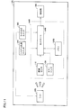
- FIG. 11 is an overall configuration diagram of an abnormality detection system to which the abnormality detection device according to the third embodiment is applied.
- abnormality notification system 10B includes an abnormality detection device 100B instead of abnormality detection device 100 according to the first embodiment or abnormality detection device 100A according to the second embodiment.
- Other configurations are the same as those in the first and second embodiments.
- the abnormality detection device 100B detects an abnormality of the light 200.
- the abnormality detection device 100B includes an illuminance sensor 110, a color sensor 110A, a memory 120B, and a controller 130B.
- the illuminance sensor 110 detects the illuminance of the light 200.
- the color sensor 110 ⁇ / b> A detects color information of light emitted from the light 200.
- abnormality detection using the illuminance of the light 200 detected by the illuminance sensor 110 and abnormality detection using the color information of the light 200 detected by the color sensor 110A. Both are performed.
- the color sensor 110A can detect illuminance in addition to color information.
- the abnormality of the illuminance sensor 110 or the color sensor 110A is detected by using the illuminance information detected by the color sensor 110A.
- An abnormality detection method of the illuminance sensor 110 or the color sensor 110A will be described in detail later.
- the memory 120B stores a reference illuminance and a reference distance that are used as a reference for detecting an abnormality of the light 200.
- the reference illuminance is used for abnormality detection of the light 200 using the illuminance sensor 110 as in the first embodiment
- the reference distance is used for abnormality detection of the light 200 using the color sensor 110A as in the second embodiment. It is done.
- the controller 130B detects an abnormality of the illuminance sensor 110 or the color sensor 110A using the illuminance detected by the illuminance sensor 110 and the illuminance detected by the color sensor 110A. If both the illuminance sensor 110 and the color sensor 110A are normal, the illuminance detected by the illuminance sensor 110 and the illuminance detected by the color sensor 110A should be substantially the same.
- the controller 130B determines that the illuminance sensor 110 or the color sensor 110A is abnormal when the difference between the illuminance detected by the illuminance sensor 110 and the illuminance detected by the color sensor 110A exceeds a second predetermined value. judge. That is, the controller 130B performs mutual monitoring of the illuminance sensor 110 and the color sensor 110A.
- the second predetermined value for example, a value is set in advance so that a difference in detection result caused by individual differences between the illuminance sensor 110 and the color sensor 110A is not erroneously detected as an abnormality of the illuminance sensor 110 or the color sensor 110A.
- the abnormality detection apparatus 100B the abnormality of the illuminance sensor 110 or the color sensor 110A can be detected.
- a specific processing procedure for detecting an abnormality of the illuminance sensor 110 or the color sensor 110A will be described.
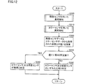
- FIG. 12 is a flowchart illustrating a processing procedure for detecting an abnormality of the illuminance sensor 110 or the color sensor 110A. Referring to FIG. 12, the process shown by this flowchart is repeatedly executed by being called from a main routine (not shown) in controller 130B during operation of abnormality notification system 10B.
- the controller 130B detects an abnormality of the light 200 using the illuminance sensor 110 (step S300). This is the abnormality detection of the light 200 described in the first embodiment. As described above, the illuminance information of the light 200 is acquired in the process of detecting the abnormality of the light 200 using the illuminance sensor 110. In the third embodiment, even if an abnormality of the light 200 is detected in step S300, the process proceeds to step S310 without returning to the main routine.
- the controller 130B detects an abnormality of the light 200 using the color sensor 110A (step S310).
- This is the abnormality detection of the light 200 described in the second embodiment. It is assumed that the illuminance information of the light 200 is acquired in the process of detecting the abnormality of the light 200 using the color sensor 110A.
- the process proceeds to step S320 without returning to the main routine.
- the controller 130B calculates a difference I1 between the illuminance detected by the illuminance sensor 110 in step S300 and the illuminance detected by the color sensor 110A in step S310 (step S320).
- the controller 130B determines whether or not the difference I1 exceeds the above-described second predetermined value (step S330). If it is determined that the difference I1 exceeds the second predetermined value (YES in step S330), the controller 130B can detect the difference between the illuminance sensor 110 and the color sensor 110A. 110 or the color sensor 110A is determined to be abnormal. On the other hand, when it is determined that difference I1 is equal to or smaller than the second predetermined value (NO in step S330), controller 130B determines that both illuminance sensor 110 and color sensor 110A are normal (step S350). Thereafter, the process is returned to the main routine.
- controller 130B determines that the difference between the illuminance detected by illuminance sensor 110 and the illuminance detected by color sensor 110A exceeds the second predetermined value. If it is determined that the illuminance sensor 110 or the color sensor 110A is abnormal. According to this abnormality detection device 100B, an abnormality of the illuminance sensor 110 or the color sensor 110A can be detected, and as a result, an abnormality of the light 200 can be accurately detected.
- Embodiments 1 to 3 As described above, Embodiments 1 to 3 have been described as embodiments of the present invention. However, the present invention is not necessarily limited to the first to third embodiments. Here, an example of another embodiment will be described.
- a predetermined fixed value is used as the reference amount and the first predetermined value.
- the reference amount and the first predetermined value are not necessarily fixed values.
- the reference amount and the first predetermined value may be updated via the Internet.
- the reference amount and the first predetermined value acquired through the Internet are generated using big data.
- a large number of data at the time of the failure of the light 200 in the abnormality notification system 10, 10A is collected through the Internet, and the optimum reference amount and the first predetermined value are sequentially updated based on the collected many data.
- the abnormality notification system 10, 10A can detect the abnormality of the light 200 more accurately by appropriately acquiring the latest reference amount and the first predetermined value.
- 10, 10A, 10B abnormality notification system 100, 100A, 100B abnormality detection device, 110 illuminance sensor, 110A color sensor, 120, 120A, 120B memory, 130, 130A, 130B controller, 200 light, 300 notification unit, 350 system activation Switch, 360 light switch.
Landscapes
- Engineering & Computer Science (AREA)
- Mechanical Engineering (AREA)
- Circuit Arrangement For Electric Light Sources In General (AREA)
Abstract
Un dispositif de détection d'anomalies (100) détecte des anomalies dans une lumière (200). Le dispositif de détection d'anomalies (100) est pourvu d'un capteur de luminosité (110), d'une mémoire (120) et d'un contrôleur (130). Le contrôleur (13) détecte : la différence entre la luminosité détectée par le capteur de luminosité (110) lorsque la lumière (200) est allumée et la luminosité détectée par le capteur de luminosité (110) lorsque la lumière (200) est éteinte ; et les anomalies de la lumière (200) sur la base d'une référence mémorisée dans la mémoire (120).
Priority Applications (2)
| Application Number | Priority Date | Filing Date | Title |
|---|---|---|---|
| US16/095,794 US10493915B2 (en) | 2016-05-24 | 2017-05-12 | Abnormality detection apparatus and notification apparatus |
| JP2018519189A JP6905517B2 (ja) | 2016-05-24 | 2017-05-12 | 異常検知装置及び報知装置 |
Applications Claiming Priority (2)
| Application Number | Priority Date | Filing Date | Title |
|---|---|---|---|
| JP2016-103280 | 2016-05-24 | ||
| JP2016103280 | 2016-05-24 |
Publications (1)
| Publication Number | Publication Date |
|---|---|
| WO2017204005A1 true WO2017204005A1 (fr) | 2017-11-30 |
Family
ID=60411240
Family Applications (1)
| Application Number | Title | Priority Date | Filing Date |
|---|---|---|---|
| PCT/JP2017/018001 Ceased WO2017204005A1 (fr) | 2016-05-24 | 2017-05-12 | Dispositif de détection d'anomalies et dispositif de notification |
Country Status (3)
| Country | Link |
|---|---|
| US (1) | US10493915B2 (fr) |
| JP (1) | JP6905517B2 (fr) |
| WO (1) | WO2017204005A1 (fr) |
Families Citing this family (4)
| Publication number | Priority date | Publication date | Assignee | Title |
|---|---|---|---|---|
| US11383641B2 (en) * | 2018-11-28 | 2022-07-12 | Honda Motor Co., Ltd. | System and method for a remote vehicle light check |
| US11479175B2 (en) * | 2019-06-21 | 2022-10-25 | Grote Industries, Llc | Error detection system and method in a vehicle lighting system |
| CN114222413B (zh) * | 2021-12-22 | 2023-09-12 | 惠州祺瑞电工有限公司 | 一种照明系统的故障自检方法及照明系统 |
| CN116653770B (zh) * | 2023-07-27 | 2023-11-21 | 浙江省标准化研究院(金砖国家标准化(浙江)研究中心、浙江省物品编码中心) | 一种道路机动车用光源安全评估预警系统 |
Citations (7)
| Publication number | Priority date | Publication date | Assignee | Title |
|---|---|---|---|---|
| JPH03211426A (ja) * | 1990-01-17 | 1991-09-17 | Nippondenso Co Ltd | 輝度検出装置 |
| JP2001338782A (ja) * | 2000-03-23 | 2001-12-07 | Olympus Optical Co Ltd | 照明用光源装置 |
| JP2009252394A (ja) * | 2008-04-02 | 2009-10-29 | Sharp Corp | 太陽電池照明装置 |
| JP2010200985A (ja) * | 2009-03-04 | 2010-09-16 | Oiwa Machinery Corp | ショーケースの照明方法及び照明装置 |
| JP2012113909A (ja) * | 2010-11-24 | 2012-06-14 | Panasonic Corp | 照明器具 |
| JP2012177576A (ja) * | 2011-02-25 | 2012-09-13 | Denso Corp | 光検出装置 |
| JP2016058240A (ja) * | 2014-09-10 | 2016-04-21 | パナソニックIpマネジメント株式会社 | 発光素子点灯装置、発光モジュール、および照明装置 |
Family Cites Families (7)
| Publication number | Priority date | Publication date | Assignee | Title |
|---|---|---|---|---|
| DE19852351A1 (de) * | 1998-11-13 | 2000-05-18 | Hella Kg Hueck & Co | Diagnosesystem für eine LED-Leuchte in einem Kraftfahrzeug |
| JP2007265287A (ja) | 2006-03-29 | 2007-10-11 | Fujitsu Ltd | 照明の劣化による画像認識精度低下を軽減する方法、装置およびシステム |
| CN101408297B (zh) * | 2007-10-12 | 2010-06-02 | 富准精密工业(深圳)有限公司 | 可远程监控的发光二极管灯具及其远程监控方法 |
| US9552438B2 (en) * | 2013-05-17 | 2017-01-24 | Paypal, Inc. | Systems and methods for responsive web page delivery based on network bandwidth |
| US11324089B2 (en) * | 2014-02-25 | 2022-05-03 | Lumenetix, Llc | Color mixing model provisioning for light-emitting diode-based lamps |
| JP6452172B2 (ja) * | 2014-09-30 | 2019-01-16 | Necディスプレイソリューションズ株式会社 | 照明装置、ホイール劣化検出方法及びプロジェクタ |
| JP6643645B2 (ja) * | 2015-02-17 | 2020-02-12 | スタンレー電気株式会社 | 車両用灯具 |
-
2017
- 2017-05-12 WO PCT/JP2017/018001 patent/WO2017204005A1/fr not_active Ceased
- 2017-05-12 US US16/095,794 patent/US10493915B2/en active Active
- 2017-05-12 JP JP2018519189A patent/JP6905517B2/ja active Active
Patent Citations (7)
| Publication number | Priority date | Publication date | Assignee | Title |
|---|---|---|---|---|
| JPH03211426A (ja) * | 1990-01-17 | 1991-09-17 | Nippondenso Co Ltd | 輝度検出装置 |
| JP2001338782A (ja) * | 2000-03-23 | 2001-12-07 | Olympus Optical Co Ltd | 照明用光源装置 |
| JP2009252394A (ja) * | 2008-04-02 | 2009-10-29 | Sharp Corp | 太陽電池照明装置 |
| JP2010200985A (ja) * | 2009-03-04 | 2010-09-16 | Oiwa Machinery Corp | ショーケースの照明方法及び照明装置 |
| JP2012113909A (ja) * | 2010-11-24 | 2012-06-14 | Panasonic Corp | 照明器具 |
| JP2012177576A (ja) * | 2011-02-25 | 2012-09-13 | Denso Corp | 光検出装置 |
| JP2016058240A (ja) * | 2014-09-10 | 2016-04-21 | パナソニックIpマネジメント株式会社 | 発光素子点灯装置、発光モジュール、および照明装置 |
Also Published As
| Publication number | Publication date |
|---|---|
| US10493915B2 (en) | 2019-12-03 |
| JPWO2017204005A1 (ja) | 2019-03-22 |
| JP6905517B2 (ja) | 2021-07-21 |
| US20190126822A1 (en) | 2019-05-02 |
Similar Documents
| Publication | Publication Date | Title |
|---|---|---|
| JP5615862B2 (ja) | 車両周囲監視装置 | |
| JP4853160B2 (ja) | 車両検出装置及びヘッドランプ制御装置 | |
| US10421389B2 (en) | Vehicle lighting system | |
| JP6905517B2 (ja) | 異常検知装置及び報知装置 | |
| US20220289101A1 (en) | Vehicle detecting device, vehicle lamp system, vehicle detecting method, light distribution controlling device, and light distribution controlling method | |
| WO2018092709A1 (fr) | Dispositif de surveillance d'état de dispositif de capture d'image, procédé de surveillance d'état de dispositif de capture d'image et programme | |
| JP6228492B2 (ja) | 車外環境認識装置 | |
| JP7517334B2 (ja) | ヘッドアップディスプレイ装置 | |
| JP6259335B2 (ja) | 車外環境認識装置 | |
| JP2011121490A (ja) | 車両用前照灯制御装置 | |
| JP7176447B2 (ja) | ライト監視装置 | |
| JP6740916B2 (ja) | 運転支援システム、運転支援方法 | |
| JP2014000908A (ja) | 光源状態検知装置、光源状態検知方法、及び光源状態検知プログラム | |
| JP2006082653A (ja) | ランプ点灯状態検出装置 | |
| US11231642B2 (en) | Light source module, projector using the same and light source control method | |
| JP7470540B2 (ja) | 内部機器の異常判定装置、異常判定方法、及びプログラム | |
| WO2017154356A1 (fr) | Dispositif de détection de ligne de visée et procédé de détection de ligne de visée | |
| JP2023552187A (ja) | 非幻惑性照明機能を用いる照明システムを制御するための方法 | |
| JP2016088281A (ja) | 操作入力装置 | |
| JP7725947B2 (ja) | オブジェクト認識制御装置およびオブジェクト認識制御方法 | |
| CN112954861A (zh) | 照明装置及照明装置及照明系统的运作方法 | |
| JP6248061B2 (ja) | ライト制御システムおよびライト制御装置 | |
| JP6425953B2 (ja) | 車両用前照灯システムの制御方法 | |
| CN116704918A (zh) | 显示检测装置、显示检测系统和显示检测方法 | |
| JP2015020625A (ja) | 車両後方照明システム |
Legal Events
| Date | Code | Title | Description |
|---|---|---|---|
| WWE | Wipo information: entry into national phase |
Ref document number: 2018519189 Country of ref document: JP |
|
| NENP | Non-entry into the national phase |
Ref country code: DE |
|
| 121 | Ep: the epo has been informed by wipo that ep was designated in this application |
Ref document number: 17802599 Country of ref document: EP Kind code of ref document: A1 |
|
| 122 | Ep: pct application non-entry in european phase |
Ref document number: 17802599 Country of ref document: EP Kind code of ref document: A1 |