WO2017204042A1 - バルーンカテーテル、及び、バルーン体の製造方法 - Google Patents
バルーンカテーテル、及び、バルーン体の製造方法 Download PDFInfo
- Publication number
- WO2017204042A1 WO2017204042A1 PCT/JP2017/018452 JP2017018452W WO2017204042A1 WO 2017204042 A1 WO2017204042 A1 WO 2017204042A1 JP 2017018452 W JP2017018452 W JP 2017018452W WO 2017204042 A1 WO2017204042 A1 WO 2017204042A1
- Authority
- WO
- WIPO (PCT)
- Prior art keywords
- balloon
- linear member
- pressing member
- linear
- outer peripheral
- Prior art date
- Legal status (The legal status is an assumption and is not a legal conclusion. Google has not performed a legal analysis and makes no representation as to the accuracy of the status listed.)
- Ceased
Links
Images


Classifications
-
- A—HUMAN NECESSITIES
- A61—MEDICAL OR VETERINARY SCIENCE; HYGIENE
- A61M—DEVICES FOR INTRODUCING MEDIA INTO, OR ONTO, THE BODY; DEVICES FOR TRANSDUCING BODY MEDIA OR FOR TAKING MEDIA FROM THE BODY; DEVICES FOR PRODUCING OR ENDING SLEEP OR STUPOR
- A61M25/00—Catheters; Hollow probes
- A61M25/10—Balloon catheters
- A61M25/104—Balloon catheters used for angioplasty
-
- A—HUMAN NECESSITIES
- A61—MEDICAL OR VETERINARY SCIENCE; HYGIENE
- A61M—DEVICES FOR INTRODUCING MEDIA INTO, OR ONTO, THE BODY; DEVICES FOR TRANSDUCING BODY MEDIA OR FOR TAKING MEDIA FROM THE BODY; DEVICES FOR PRODUCING OR ENDING SLEEP OR STUPOR
- A61M25/00—Catheters; Hollow probes
- A61M25/10—Balloon catheters
- A61M25/1002—Balloon catheters characterised by balloon shape
-
- A—HUMAN NECESSITIES
- A61—MEDICAL OR VETERINARY SCIENCE; HYGIENE
- A61M—DEVICES FOR INTRODUCING MEDIA INTO, OR ONTO, THE BODY; DEVICES FOR TRANSDUCING BODY MEDIA OR FOR TAKING MEDIA FROM THE BODY; DEVICES FOR PRODUCING OR ENDING SLEEP OR STUPOR
- A61M25/00—Catheters; Hollow probes
- A61M25/10—Balloon catheters
- A61M25/1027—Making of balloon catheters
- A61M25/1029—Production methods of the balloon members, e.g. blow-moulding, extruding, deposition or by wrapping a plurality of layers of balloon material around a mandril
-
- A—HUMAN NECESSITIES
- A61—MEDICAL OR VETERINARY SCIENCE; HYGIENE
- A61B—DIAGNOSIS; SURGERY; IDENTIFICATION
- A61B17/00—Surgical instruments, devices or methods
- A61B17/32—Surgical cutting instruments
- A61B17/3205—Excision instruments
- A61B17/3207—Atherectomy devices working by cutting or abrading; Similar devices specially adapted for non-vascular obstructions
- A61B17/320725—Atherectomy devices working by cutting or abrading; Similar devices specially adapted for non-vascular obstructions with radially expandable cutting or abrading elements
-
- A—HUMAN NECESSITIES
- A61—MEDICAL OR VETERINARY SCIENCE; HYGIENE
- A61B—DIAGNOSIS; SURGERY; IDENTIFICATION
- A61B17/00—Surgical instruments, devices or methods
- A61B17/22—Implements for squeezing-off ulcers or the like on inner organs of the body; Implements for scraping-out cavities of body organs, e.g. bones; for invasive removal or destruction of calculus using mechanical vibrations; for removing obstructions in blood vessels, not otherwise provided for
- A61B2017/22051—Implements for squeezing-off ulcers or the like on inner organs of the body; Implements for scraping-out cavities of body organs, e.g. bones; for invasive removal or destruction of calculus using mechanical vibrations; for removing obstructions in blood vessels, not otherwise provided for with an inflatable part, e.g. balloon, for positioning, blocking, or immobilisation
- A61B2017/22061—Implements for squeezing-off ulcers or the like on inner organs of the body; Implements for scraping-out cavities of body organs, e.g. bones; for invasive removal or destruction of calculus using mechanical vibrations; for removing obstructions in blood vessels, not otherwise provided for with an inflatable part, e.g. balloon, for positioning, blocking, or immobilisation for spreading elements apart
-
- A—HUMAN NECESSITIES
- A61—MEDICAL OR VETERINARY SCIENCE; HYGIENE
- A61M—DEVICES FOR INTRODUCING MEDIA INTO, OR ONTO, THE BODY; DEVICES FOR TRANSDUCING BODY MEDIA OR FOR TAKING MEDIA FROM THE BODY; DEVICES FOR PRODUCING OR ENDING SLEEP OR STUPOR
- A61M25/00—Catheters; Hollow probes
- A61M25/10—Balloon catheters
- A61M25/1002—Balloon catheters characterised by balloon shape
- A61M2025/1004—Balloons with folds, e.g. folded or multifolded
-
- A—HUMAN NECESSITIES
- A61—MEDICAL OR VETERINARY SCIENCE; HYGIENE
- A61M—DEVICES FOR INTRODUCING MEDIA INTO, OR ONTO, THE BODY; DEVICES FOR TRANSDUCING BODY MEDIA OR FOR TAKING MEDIA FROM THE BODY; DEVICES FOR PRODUCING OR ENDING SLEEP OR STUPOR
- A61M25/00—Catheters; Hollow probes
- A61M25/10—Balloon catheters
- A61M25/1027—Making of balloon catheters
- A61M25/1029—Production methods of the balloon members, e.g. blow-moulding, extruding, deposition or by wrapping a plurality of layers of balloon material around a mandril
- A61M2025/1031—Surface processing of balloon members, e.g. coating or deposition; Mounting additional parts onto the balloon member's surface
-
- A—HUMAN NECESSITIES
- A61—MEDICAL OR VETERINARY SCIENCE; HYGIENE
- A61M—DEVICES FOR INTRODUCING MEDIA INTO, OR ONTO, THE BODY; DEVICES FOR TRANSDUCING BODY MEDIA OR FOR TAKING MEDIA FROM THE BODY; DEVICES FOR PRODUCING OR ENDING SLEEP OR STUPOR
- A61M25/00—Catheters; Hollow probes
- A61M25/10—Balloon catheters
- A61M2025/1043—Balloon catheters with special features or adapted for special applications
- A61M2025/1061—Balloon catheters with special features or adapted for special applications having separate inflations tubes, e.g. coaxial tubes or tubes otherwise arranged apart from the catheter tube
-
- A—HUMAN NECESSITIES
- A61—MEDICAL OR VETERINARY SCIENCE; HYGIENE
- A61M—DEVICES FOR INTRODUCING MEDIA INTO, OR ONTO, THE BODY; DEVICES FOR TRANSDUCING BODY MEDIA OR FOR TAKING MEDIA FROM THE BODY; DEVICES FOR PRODUCING OR ENDING SLEEP OR STUPOR
- A61M25/00—Catheters; Hollow probes
- A61M25/10—Balloon catheters
- A61M2025/1043—Balloon catheters with special features or adapted for special applications
- A61M2025/1084—Balloon catheters with special features or adapted for special applications having features for increasing the shape stability, the reproducibility or for limiting expansion, e.g. containments, wrapped around fibres, yarns or strands
-
- A—HUMAN NECESSITIES
- A61—MEDICAL OR VETERINARY SCIENCE; HYGIENE
- A61M—DEVICES FOR INTRODUCING MEDIA INTO, OR ONTO, THE BODY; DEVICES FOR TRANSDUCING BODY MEDIA OR FOR TAKING MEDIA FROM THE BODY; DEVICES FOR PRODUCING OR ENDING SLEEP OR STUPOR
- A61M2205/00—General characteristics of the apparatus
- A61M2205/02—General characteristics of the apparatus characterised by a particular materials
- A61M2205/0238—General characteristics of the apparatus characterised by a particular materials the material being a coating or protective layer
-
- A—HUMAN NECESSITIES
- A61—MEDICAL OR VETERINARY SCIENCE; HYGIENE
- A61M—DEVICES FOR INTRODUCING MEDIA INTO, OR ONTO, THE BODY; DEVICES FOR TRANSDUCING BODY MEDIA OR FOR TAKING MEDIA FROM THE BODY; DEVICES FOR PRODUCING OR ENDING SLEEP OR STUPOR
- A61M2205/00—General characteristics of the apparatus
- A61M2205/32—General characteristics of the apparatus with radio-opaque indicia
-
- A—HUMAN NECESSITIES
- A61—MEDICAL OR VETERINARY SCIENCE; HYGIENE
- A61M—DEVICES FOR INTRODUCING MEDIA INTO, OR ONTO, THE BODY; DEVICES FOR TRANSDUCING BODY MEDIA OR FOR TAKING MEDIA FROM THE BODY; DEVICES FOR PRODUCING OR ENDING SLEEP OR STUPOR
- A61M2207/00—Methods of manufacture, assembly or production
-
- A—HUMAN NECESSITIES
- A61—MEDICAL OR VETERINARY SCIENCE; HYGIENE
- A61M—DEVICES FOR INTRODUCING MEDIA INTO, OR ONTO, THE BODY; DEVICES FOR TRANSDUCING BODY MEDIA OR FOR TAKING MEDIA FROM THE BODY; DEVICES FOR PRODUCING OR ENDING SLEEP OR STUPOR
- A61M25/00—Catheters; Hollow probes
- A61M25/10—Balloon catheters
-
- B—PERFORMING OPERATIONS; TRANSPORTING
- B29—WORKING OF PLASTICS; WORKING OF SUBSTANCES IN A PLASTIC STATE IN GENERAL
- B29K—INDEXING SCHEME ASSOCIATED WITH SUBCLASSES B29B, B29C OR B29D, RELATING TO MOULDING MATERIALS OR TO MATERIALS FOR MOULDS, REINFORCEMENTS, FILLERS OR PREFORMED PARTS, e.g. INSERTS
- B29K2077/00—Use of PA, i.e. polyamides, e.g. polyesteramides or derivatives thereof, as moulding material
Definitions
- the present invention relates to a balloon catheter and a method for manufacturing a balloon body.
- Balloon catheters used for the treatment of dilating stenotic blood vessels are known.
- a balloon catheter having a linear member on the surface of the balloon has been proposed.
- the linear member acts on the blood vessel with the balloon expanded.
- the balloon catheter can appropriately expand the lesion from the inside of the blood vessel by inflation of the balloon.
- Patent Document 1 discloses a balloon catheter including a balloon having a plurality of wings as a linear member.
- the plurality of wings are relatively harder than the balloon.
- the plurality of wings extend radially outward when the balloon is inflated. For this reason, the plurality of wings exerts a high pressure on the blood vessel tissue due to the inflation of the balloon.
- Two methods are exemplified as a method of forming a plurality of wings on the balloon. The first is a method of forming a part of a balloon as a plurality of wings.
- the second is a method of attaching a material other than the balloon to the balloon by welding, adhesion, fusion or the like.
- the linear member When a linear member made of a material different from the balloon is joined to the balloon, the linear member is easily detached from the balloon according to the inflation of the balloon. When the linear member is detached from the balloon, the position of the linear member may deviate from a desired position. When the linear member is not joined to the balloon, the position of the linear member may deviate from a desired position in accordance with the inflation of the balloon. As described above, the position of the linear member at least a part of which is arranged on the outer peripheral surface of the balloon can be shifted from a desired position according to the inflation of the balloon.
- An object of the present invention is to provide a balloon catheter in which a linear member is difficult to be displaced from a desired position of a balloon when the balloon is inflated, and a method for manufacturing a balloon body.
- the balloon catheter according to the first aspect of the present invention includes a catheter shaft extending in the extending direction from the proximal end to the distal end, and a balloon that is provided on the catheter shaft and that is inflatable outward in the radial direction around the catheter shaft. And a linear member that is disposed on at least a part of the outer peripheral surface of the balloon and extends along the extending direction, and a pressing member that presses the linear member against the balloon.
- the balloon catheter has a pressing member that presses the linear member against the balloon. For this reason, the balloon catheter can suppress displacement of the linear member with respect to the balloon when the balloon is inflated, as compared with a case where the linear member is attached to the balloon by welding, adhesion, fusion, or the like.
- the pressing member has a film part covering at least a part of the outer peripheral surface of the balloon, and at least a part of the linear member is disposed between the film part and the balloon.
- the balloon catheter can suppress displacement of the linear member relative to the balloon by pressing the linear member against the balloon by the membrane portion.
- a balloon catheter can suppress that the diameter of the whole balloon is expanded by a press member by making the press member which presses a linear member against a balloon into a film
- the film part may cover the entire outer peripheral surface of the balloon.
- the balloon catheter can more appropriately suppress the displacement of the linear member when the balloon is inflated by covering the entire balloon with the membrane portion.
- the said linear member is arrange
- region is a partial area
- a region having a substantially constant diameter along the stretching direction may be used.
- the balloon catheter can appropriately cause the linear member to act on the blood vessel in the inflated region having a substantially constant diameter.
- the linear member includes an inflating portion disposed in the inflating region of the balloon, a tip portion positioned on the tip side with respect to the inflating region, and the base with respect to the inflating region. You may provide at least one of the base end parts located in an end side.
- the balloon catheter can increase the contact area between the outer peripheral surface of the balloon and the linear member as compared with the case where the linear member has only the inflated portion. For this reason, when the positional deviation of the linear member is suppressed by the contact portion between the linear member and the balloon, the positional displacement of the linear member can be appropriately suppressed by increasing the contact area.
- positioned among the said linear members on the opposite side to the inner side part which opposes the said balloon may be harder than the said balloon.
- the balloon catheter can appropriately cause the linear member to act on the blood vessel when the balloon is inflated.
- the linear member may include at least the inner portion and include a stretchable soft portion and at least the outer portion and a hard portion that is harder than the soft portion. .
- the linear member can appropriately cause the hard part to act on the blood vessel when the balloon is inflated.
- the flexible part of the linear member can be stretched.
- the balloon catheter can cause the linear member to follow the inflation of the balloon by extending the flexible portion in accordance with the inflation of the balloon. Therefore, the balloon catheter can prevent the linear member from being displaced relative to the balloon when the balloon is inflated, and the linear member from inhibiting the inflation of the balloon.
- the linear member may be bonded to the balloon.
- the linear member in addition to the linear member being pressed against the balloon by the pressing member, the linear member is directly joined to the balloon.
- the balloon catheter can further appropriately prevent the linear member from being displaced with respect to the balloon.
- the pressing member may have a joint portion disposed between the balloon and the linear member, and the linear member may be joined to the balloon by the joint portion.
- the pressing member can directly join the linear member to the balloon by the joint portion at the same time as pressing the linear member against the balloon.
- the balloon catheter can suppress the displacement of the linear member with respect to the balloon by the pressing member, and can also suppress the displacement of the linear member with respect to the catheter shaft.
- a method for manufacturing a balloon body according to a second aspect of the present invention is a manufacturing method for manufacturing a balloon body including the balloon, the linear member, and the pressing member according to the first aspect, A step of arranging the linear member on the outer peripheral surface, a step of applying a melt obtained by melting the material of the pressing member to the balloon in a state where the linear member is disposed on the outer peripheral surface, and after application, Drying the melt adhered to the balloon and the linear member to form the pressing member.
- the linear member is firmly pressed against the outer peripheral surface of the balloon by the pressing member. Therefore, it is possible to easily manufacture a balloon body in which the linear member is not easily displaced with respect to the balloon.
- a method for manufacturing a balloon body according to a third aspect of the present invention is a manufacturing method for manufacturing a balloon body including the balloon, the linear member, and the pressing member according to the first aspect, and includes an inner wall of a mold.
- the step of disposing the pressing member along the line, the step of disposing the linear member on the side opposite to the mold with respect to the pressing member, and the side opposite to the pressing member with respect to the linear member And a step of discharging a parison as a base of the balloon and a step of blowing air into the inside of the parison, and the air is blown into the inside of the parison so that the parison is pressed against the mold.
- a balloon is formed, and the pressing member and the linear member are in close contact with the balloon.
- the linear member is firmly pressed against the outer peripheral surface of the balloon by the pressing member. Therefore, it is possible to manufacture a balloon body in which the linear member is not easily displaced with respect to the balloon.
- the balloon body can be manufactured using the solid pressing member as it is. Therefore, it can suppress that the physical property of a press member changes because the state of a press member changes at the time of manufacture.
- a method for manufacturing a balloon body according to a fourth aspect of the present invention is a manufacturing method for manufacturing a balloon body including the balloon, the linear member, and the pressing member according to the first aspect, The step of disposing the linear member on the outer peripheral surface and the film-shaped pressing member cover at least a part of the linear member from the outside of the linear member, and the pressing member is disposed on the outer peripheral surface. And a step of attaching.
- a balloon body in which the linear member is pressed against the outer peripheral surface of the balloon by the pressing member can be easily manufactured.
- a method for manufacturing a balloon body according to a fifth aspect of the present invention is a manufacturing method for manufacturing a balloon body including the balloon, the linear member, and the pressing member according to the first aspect, The step of disposing the linear member on the outer peripheral surface, the step of covering the linear member from the outside of the linear member by the pressing member having heat shrinkability, and the linear member being covered by the pressing member. A step of heating the pressing member in a broken state and contracting the pressing member. In this case, the pressing member can be brought into close contact with the balloon and the linear member. Since it is a dry manufacturing method, the balloon body can be easily manufactured without requiring large-scale equipment.
- FIG. 3 is a cross-sectional view of the II line in FIG. 2 as viewed from the direction of the arrow. It is sectional drawing of the balloon catheter 10 in a contracted state. It is a side view of the balloon catheter 10 in an expanded state. It is sectional drawing of the balloon catheter 10 in an expanded state.
- FIG. 6 is a cross-sectional view taken along the line II-II in FIG.
- FIG. 6 is a cross-sectional view taken along the line II-II in FIG. It is a side view of the balloon catheter 20 in 2nd Embodiment.
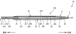
- the balloon catheter 10 includes a catheter shaft 2, a balloon 3, linear members 41 ⁇ / b> A, 41 ⁇ / b> B, and 41 ⁇ / b> C (refer to FIG. 3 and the like, hereinafter collectively referred to as “linear members 41”).
- a pressing member 6 is provided.
- the balloon 3 is connected to one end of the catheter shaft 2.
- one end of both ends of the catheter shaft 2 is referred to as a “tip”.
- the other end of both ends of the catheter shaft 2 is referred to as a “base end”.
- the linear member 41 is located on the outer peripheral surface 3D of the balloon 3 (see FIG. 2).
- the pressing member 6 covers the balloon 3 and the linear member 41 and presses the linear member 41 against the balloon 3.
- the balloon 3, the linear member 41, and the pressing member 6 are referred to as “balloon body 10A”.
- the balloon catheter 10 is used in a state where the hub 5 is connected to the proximal end of the catheter shaft 2.
- the hub 5 can supply a compressed fluid to the balloon 3 via the catheter shaft 2.
- the direction extending along the catheter shaft 2 is referred to as “stretching direction”.
- the side close to the cross-sectional center of the catheter shaft 2 is referred to as “inside” and is separated from the cross-sectional center of the catheter shaft 2.
- the side is called “outside”.
- the catheter shaft 2 includes an outer tube 21 and an inner tube 22.
- the outer tube 21 and the inner tube 22 are each a tubular member having flexibility.
- the outer tube 21 has a lumen 213 that is a space surrounded by an inner surface 212 that is an inner surface.
- the inner tube 22 has a lumen 223 that is a space surrounded by an inner surface 222 that is an inner surface.
- the outer tube 21 and the inner tube 22 are made of polyamide resin.
- the inner diameter of the outer tube 21 is larger than the outer diameter of the inner tube 22.
- the inner tube 22 is disposed in the lumen 213 of the outer tube 21 except for a predetermined portion on the distal end side.
- the predetermined portion on the distal end side of the inner tube 22 protrudes from the distal end side of the outer tube 21 (hereinafter referred to as “distal end 211”) toward the distal end side.
- distal end 211 the end on the distal end side of the inner tube 22
- distal end 221 is disposed on the distal end side with respect to the distal end 211 of the outer tube 21.
- the predetermined portion on the distal end side of the inner tube 22 is referred to as a “projection portion 225”.
- Radiopaque markers (hereinafter simply referred to as “markers”) 22 ⁇ / b> A and 22 ⁇ / b> B are attached to the protruding portion 225 of the inner tube 22.
- markers 22A and 22B a resin mixed with a radiopaque material is used.
- the markers 22 ⁇ / b> A and 22 ⁇ / b> B are fixed to the outer peripheral surface 224 of the projecting portion 225 of the inner tube 22 by caulking the cylindrical member formed of the above material to the projecting portion 225 of the inner tube 22.
- the markers 22A and 22B have a predetermined length in the extending direction.
- the markers 22A and 22B do not transmit radiation.
- the marker 22A is arranged on the tip side of the marker 22B.
- the markers 22A and 22B are separated in the extending direction.
- Compressed fluid supplied from the hub 5 flows through a space other than the lumen 223 of the inner tube 22 in the lumen 213 of the outer tube 21.
- the balloon 3 is expanded in response to the supply of the compressed fluid (see FIGS. 5 to 8).
- a guide wire (not shown) is inserted into the lumen 223 of the inner tube 22.
- the material of the outer tube 21 and the inner tube 22 is not limited to the polyamide-based resin, but can be changed to another material having flexibility.
- a synthetic resin material such as a polyethylene resin, a polypropylene resin, a polyurethane resin, or a polyimide resin may be used.
- An additive may be mixed in the synthetic resin material.
- Different synthetic resin materials may be used as the materials of the outer tube 21 and the inner tube 22.
- the material of the markers 22 ⁇ / b> A and 22 ⁇ / b> B is not limited to the resin mixed with the radiopaque material, and can be changed to another material that does not allow the radiation to pass.
- a resin on which a radiopaque material is deposited, or a material that does not transmit radiation, such as metal may be used.
- the balloon 3 contracts inward in a state where no compressed fluid is supplied.
- the balloon 3 is inflated to the outside in a state where the compressed fluid is supplied.
- the balloon 3 is made of a polyamide resin.
- the balloon 3 has a proximal leg portion 31, a proximal cone region 32, an inflation region 33, a distal cone region 34, and a distal leg portion 35. .
- the proximal end leg portion 31, the proximal end cone region 32, the expansion region 33, the distal end side cone region 34, and the distal end side leg portion 35 correspond to the respective portions obtained by dividing the balloon 3 into five along the extending direction.
- the length of the expansion region 33 in the extending direction is longer than the length of each of the proximal end leg portion 31, the proximal end cone region 32, the distal end side cone region 34, and the distal end side leg portion 35 in the extending direction.
- the proximal end leg portion 31 is connected to the proximal end portion of the outer peripheral surface 214 of the outer tube 21 with respect to the proximal end side by thermal welding.
- the proximal end cone region 32 is adjacent to the distal end side with respect to the proximal end leg portion 31.
- the expansion region 33 is adjacent to the proximal end side cone region 32 on the distal end side.
- the distal cone region 34 is adjacent to the distal side with respect to the expansion region 33.
- the distal leg portion 35 is adjacent to the distal end side with respect to the distal cone region 34.
- the distal leg portion 35 is connected to a portion of the outer peripheral surface 224 of the protruding portion 225 of the inner tube 22 on the proximal end side with respect to the distal end 221 by thermal welding.
- the proximal end leg portion 31, the proximal end cone region 32, the expansion region 33, the distal end side cone region 34, and the distal end side leg portion 35 are arranged in order from the proximal end side toward the distal end side.
- the proximal end cone region 32, the expansion region 33, the distal end side cone region 34, and the distal end side leg portion 35 cover the protruding portion 225 of the inner tube 22 from the outside.
- the balloon 3 is a three-blade type balloon in which three blades are formed in a contracted state.
- the balloon 3 is folded so that wings 3A, 3B, and 3C are formed in the contracted state.
- the wings 3 ⁇ / b> A, 3 ⁇ / b> B, 3 ⁇ / b> C wrap around the protruding portion 225 of the inner tube 22.
- the wing 3A covers a linear member 41A described later from the outside.
- the wing 3B covers a linear member 41B described later from the outside.
- the wing 3C covers a linear member 41C described later from the outside.
- the wings 3A, 3B, and 3C are also called “flaps” and “wings”.
- the cross-sectional shape of the balloon 3 is circular.
- the proximal cone region 32 has a tapered shape.
- the proximal cone region 32 has a diameter that increases continuously and linearly from the proximal end toward the distal end.
- the expansion region 33 extends in the extending direction.
- the diameter of the expansion region 33 is substantially constant over the entire region in the stretching direction.
- the distal cone region 34 has a tapered shape.
- the distal cone region 34 has a diameter that decreases continuously and linearly from the proximal end toward the distal end.
- the diameter of the cross section of the balloon 3 changes in a stepwise manner between the proximal cone region 32, the inflation region 33, and the distal cone region 34.
- the inflation region 33 is the largest outer diameter portion of the balloon 3.
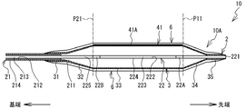
- the position of the boundary on the tip side of the expansion region 33 in other words, the position of the boundary between the expansion region 33 and the tip side cone region 34 is the position P11 of the end portion on the tip side of the marker 22A in the extending direction.
- the base end side boundary of the expansion region 33 in other words, the position of the boundary between the expansion region 33 and the base end cone region 32 coincides with the position P21 of the base end side end of the marker 22B in the extending direction.
- the material of the balloon 3 is not limited to the polyamide resin, but can be changed to another material having flexibility.
- polyethylene resin, polypropylene resin, polyurethane resin, polyimide resin, silicon rubber, natural rubber, or the like may be used as the material of the balloon 3.
- the connection method between the outer tube 21 and the inner tube 22 and the balloon 3 and the connection method between the outer tube 21 and the mounting member 21A are not limited to thermal welding. For example, each may be connected by an adhesive.
- the linear member 41 will be described with reference to FIGS.
- the linear member 41 is a monofilament-shaped elastic body having a restoring force against bending deformation.
- the linear members 41A, 41B, and 41C have the same shape.
- the linear member 41 extends along the extending direction.
- the linear member 41 is disposed on the outer peripheral surface 3D (see FIGS. 5 and 7) of the inflation region 33 of the balloon 3.
- the linear member 41 is pressed against the balloon 3 by the pressing member 6 described later.
- a portion of the linear member 41 facing the balloon 3 (hereinafter referred to as “inner portion 410” (see FIG. 8)) is in contact with the outer peripheral surface 3D of the balloon 3.
- the linear member 41 is movable with respect to the outer peripheral surface 3D of the balloon 3.
- the inner portion 410 is not joined to the outer peripheral surface 3D of the balloon 3.
- the position of the end portion on the proximal end side of the linear member 41 substantially coincides with the boundary position between the expansion region 33 and the proximal end cone region 32.
- the position of the end portion on the distal end side of the linear member 41 substantially coincides with the boundary position between the expansion region 33 and the distal end side cone region 34.
- the linear member 41 is not disposed on the outer peripheral surface 3 ⁇ / b> D of each of the proximal leg portion 31, the proximal cone region 32, the distal cone region 34, and the distal leg portion 35 of the balloon 3.
- the linear members 41A, 41B, 41C extend linearly in the extending direction at respective positions obtained by dividing the balloon 3 into approximately three equal parts in the circumferential direction.
- the cross-sectional shape of the linear member 41 is an equilateral triangle having the inner portion 410 as a base.
- the outermost part of the outer part 411 facing the inner part 410 that is, the apex part 412 of the equilateral triangle in FIG.
- the linear member 41 is made of a polyamide resin.
- the hardness of the linear member 41 is a value within the range of D70 to D95 according to ISO868.
- the linear member 41 is harder than the balloon 3 over the entire region from the inner portion 410 to the outer portion 411. In this case, the linear member 41 is less likely to expand and contract in the extending direction than the balloon 3.
- the balloon 3 may be harder than the linear member 41.
- the linear member 41 may be able to expand and contract better in the extending direction than the balloon 3.
- the pressing member 6 is a film-like member that covers the entire balloon 3.
- the pressing member 6 includes the entire outer peripheral surface 3D of the balloon 3, more specifically, the proximal end leg portion 31, the proximal end cone region 32, the inflation region 33, the distal cone region 34, and the distal leg of the balloon 3. All of the outer peripheral surfaces 3D of the part 35 are covered.
- the pressing member 6 includes a first film part 61 and a second film part 62.
- membrane part 61 is a part which contacts the linear member 41 among the press members 6, and directly covers the linear member 41 from the outer side.
- the first film portion 61 sandwiches the linear member 41 between the outer peripheral surface 3D of the balloon 3.
- the first film unit 61 is in close contact with the outer portion 411 of the linear member 41.
- membrane part 62 is a part which contacts the outer peripheral surface 3D of the balloon 3 among the press members 6, and directly covers outer peripheral surface 3D from the outer side.
- the second film portion 62 is in close contact with the outer peripheral surface 3D of the balloon 3.
- the linear member 41 is pressed against the balloon 3 by the elasticity of the pressing member 6. For this reason, the movement of the linear member 41 with respect to the balloon 3 is suppressed by the pressing member 6.
- the force with which the pressing member 6 presses the linear member 41 toward the balloon 3 may be a force that does not allow the linear member 41 to separate from the balloon 6 when the balloon 6 is expanded. Therefore, for example, the pressing member 6 may be an elastic member positioned along the outer periphery of the linear member 41 and the expanded balloon 6.
- the pressing member 6 may have a shape along the outer surface of the linear member 41 and the expanded balloon 6 in a state where no force is applied to the pressing member 6. In this case, movement of the linear member 41 relative to the expanded balloon 6 is suppressed by the pressing member 6.
- the inflation region 33 of the balloon 3 extends in the extending direction.
- the inner portion 410 of the linear member 41 is not joined to the balloon 3.
- the linear member 41 is less likely to expand and contract in the extending direction than the balloon 3.
- the inner portion 410 of the linear member 41 slides in the extending direction with respect to the outer peripheral surface 3D of the balloon 3.
- the expansion of the inflation region 33 of the balloon 3 is not hindered by the linear member 41. Movement of the linear member 41 in the circumferential direction with respect to the outer peripheral surface 3D of the balloon 3 is suppressed by the pressing member 6. For this reason, the movement of the linear member 41 in the circumferential direction is suppressed by the pressing member 6 when the balloon 3 is inflated.
- the balloon 3 contracts in response to the discharge of the compressed fluid from the inflated balloon 3, the inflated region 33 of the balloon 3 in the extending direction contracts due to the restoring force. Also in this case, the inner portion 410 of the linear member 41 slides with respect to the outer peripheral surface 3D of the balloon 3 in the same manner as when the balloon 3 is inflated. For this reason, the contraction of the expansion region 33 of the balloon 3 is not hindered by the linear member 41. The inflated region 33 of the balloon 3 contracts smoothly, and the generation of wrinkles and the like on the balloon 3 is suppressed.
- the linear member 41A is covered from the outside by the wing 3A
- the linear member 41B is covered from the outside by the wing 3B
- the linear member 41C is covered from the outside by the wing 3C (see FIG. 3).
- the material of the pressing member 6 is polyethylene resin, polypropylene resin, polyurethane resin, polyimide resin, silicon rubber, natural rubber, or the like.
- the thickness of the pressing member 6 is 5 to 40 ⁇ m.
- the balloon catheter 10 has the pressing member 6 that presses the linear member 41 against the balloon 3.
- the linear member 41 is displaced with respect to the balloon 3 when the balloon 3 is inflated, compared to the case where the linear member 41 is attached to the balloon 3 by welding, adhesion, fusion, or the like. This can be suppressed.
- the linear member 41 is not directly attached to the balloon 3, the expansion of the outer peripheral surface 3 ⁇ / b> D of the inflation region 33 is not hindered when the balloon 3 is inflated.
- the balloon 3 may be bent in a direction crossing the extending direction, which is not preferable.
- the balloon catheter 10 since the expansion of the balloon 3 is difficult to be suppressed by the linear member 41, the balloon 3 can be prevented from being bent during the expansion.
- the balloon catheter 10 can prevent wrinkles and the like from being generated on the balloon 3 when the balloon 3 is deflated.
- the pressing member 6 covers all of the outer peripheral surfaces 3D of the proximal end leg portion 31, the proximal end cone region 32, the expansion region 33, the distal end side cone region 34, and the distal end side leg portion 35 of the balloon 3.
- the balloon 3 and the linear member 41 and the pressing member 6 are in close contact with each other without a gap. For this reason, since the pressing member 6 can press the whole linear member 41 against the balloon 3, it is possible to suppress the positional displacement of the linear member 41 with respect to the balloon 3.
- the balloon catheter 10 can suppress the diameter of the balloon body 10 ⁇ / b> A from being expanded by the pressing member 6 by forming the pressing member 6 into a film shape. Accordingly, the balloon catheter 10 can suppress the passage of the pressing member 6 from being caught by the inner wall of the blood vessel when the balloon body 10A moves in the blood vessel.
- the linear member 41 is disposed in the inflation region 33 of the balloon 3.
- the inflated region 33 has substantially the same diameter in the extending direction.
- the balloon catheter 30 can appropriately cause the linear member 41 to act on the blood vessel in the inflation region 33 when the balloon 3 is inflated.
- the balloon catheter 10 can appropriately cause the linear member 41 to act on the blood vessel when the balloon 3 is inflated.
- the outer portion 411 of the linear member 41 is pointed at the apex portion 412. For this reason, when the balloon 3 is inflated, the outer portion 411 is likely to bite into the vascular lesion. Therefore, the linear member 41 can expand the lesioned part from the inside by the expansion of the balloon 3 in a state in which the balloon 3 is difficult to slip with respect to the lesioned part of the blood vessel.
- a balloon catheter 20 according to a second embodiment of the present invention will be described with reference to FIG.
- a difference from the balloon catheter 10 according to the first embodiment (see FIGS. 1 to 6 and the like) is that a linear member 42 is provided instead of the linear member 41 (see FIGS. 4 to 6 and the like).
- the linear member 42 includes linear members 42A and 42B.
- the linear members 42A and 42B correspond to the linear members 41A and 41B (see FIG. 7 and the like), respectively.
- the linear member 42 further includes a linear member (not shown) corresponding to the linear member 41C (see FIG. 7).
- the balloon body 20A corresponds to the balloon body 10A in the balloon catheter 10 (see FIGS. 1 to 6 and the like).
- the linear member 42 is disposed on each of the outer peripheral surfaces 3 ⁇ / b> D of the proximal end leg portion 31, the proximal end cone region 32, and the inflation region 33 of the balloon 3.
- a portion of the linear member 42 that is disposed on the outer peripheral surface 3D of the base end side leg portion 31 and the base end side cone region 32 is referred to as a “base end side portion 421”, and the outer peripheral surface of the expansion region 33.
- a portion arranged on 3D is referred to as an “expanded portion 422”.
- the position of the proximal end portion of the proximal end portion 421 is substantially the same as the position of the proximal end portion of the proximal leg portion 31.
- the position of the end portion on the distal end side of the expanded portion 422 substantially coincides with the boundary position between the expanded region 33 and the proximal end cone region 32.
- the linear member 42 is not disposed on the outer peripheral surface 3D of the distal end side cone region 34 and the distal end side leg portion 35 of the balloon 3. The entire linear member 42 is covered from the outside by the pressing member 6.
- the balloon catheter 20 presses when the linear member 42 is displaced with respect to the balloon 3 when the balloon 3 is inflated or the linear member 42 inhibits the inflation of the balloon 3. It can be suppressed by the member 6.
- the linear member 42 is longer in the extending direction than the linear member 41.
- the balloon catheter 20 can make the area of the part which contacts the balloon 3 and the press member 6 among the linear members 42 larger than the case of the balloon catheter 10. Accordingly, the linear member 42 is pressed against the balloon 3 with a greater force than the linear member 41 of the balloon catheter 10. Therefore, the balloon catheter 20 can more reliably suppress the displacement of the linear member 42 with respect to the balloon 3 than in the case of the balloon catheter 10.
- the linear member 42 is not disposed in the distal end side cone region 34 and the distal end side leg portion 35 in the outer peripheral surface 3D of the balloon 3. For this reason, the balloon catheter 20 can further reduce the diameter of the distal end portion of the balloon body 20A. Therefore, the user can move the balloon body 20A of the balloon catheter 20 to a narrowed portion in the blood vessel with a smaller force.
- a balloon catheter 30 according to a third embodiment of the present invention will be described with reference to FIG.
- the difference from the balloon catheter 20 (see FIG. 9) according to the second embodiment is that the linear member 43 is provided instead of the linear member 42 (see FIG. 9), and that the mounting member 21A is provided. It is.
- the linear member 43 is different from the linear member 42 in that a part thereof is joined to the outer tube 21 via the mounting member 21A.
- the balloon body 30A corresponds to the balloon body 20A (see FIG. 9) in the balloon catheter 20.
- the mounting member 21 ⁇ / b> A is mounted on a portion of the outer peripheral surface 214 of the outer tube 21 that is proximal to the distal end 211 (see FIGS. 4 and 6).
- the mounting member 21A is a cylindrical member that is movable along the extending direction.
- the inner diameter of the mounting member 21 ⁇ / b> A is larger than the outer diameter of the outer tube 21.
- a thermoplastic resin such as a polyamide resin is used as the material of the mounting member 21A.
- the linear member 43 includes linear members 43A and 43B.
- the linear members 43A and 43B correspond to the linear members 42A and 42B (see FIG. 9), respectively.
- the linear member 43 further includes a linear member (not shown) corresponding to the linear member (not shown) of the linear member 42.
- the linear member 43 has a proximal end portion 431 and an expanded portion 432.
- the proximal end portion 431 and the expanded portion 432 correspond to the proximal end portion 421 and the expanded portion 422 (see FIG. 9) of the linear member 42, respectively.
- the base end of the base end portion 431 is connected to the outer peripheral surface of the mounting member 21A by heat welding. For this reason, the linear member 43 is joined to the catheter shaft 2 (outer tube 21) via the mounting member 21A.
- the linear member 43 is not connected to the balloon 3 at a portion other than the proximal end of the proximal end portion 431.
- the inflated portion 432 of the linear member 43 contacts the outer peripheral surface 3D of the inflating region 33 of the balloon 3.
- the proximal end portion 431 of the linear member 43 extends linearly from the boundary portion between the proximal end cone region 32 and the inflation region 33 of the balloon 3 toward the mounting member 21A. For this reason, the base end side part 431 does not contact each outer peripheral surface 3D of the base end side leg part 31 and the base end side cone area
- the pressing member 6 covers the entire outer peripheral surface 3D of the balloon 3.
- the inflated portion 432 of the linear member 43 is sandwiched between the outer peripheral surface 3D of the balloon 3 and the pressing member 6.
- the inflatable portion 432 is pressed against the balloon side by the elasticity of the pressing member 6. Thereby, the movement of the linear member 43 with respect to the balloon 3 is suppressed by the pressing member 6.
- the proximal end portion 431 of the linear member 43 is exposed to the outside with respect to the pressing member 6.
- the balloon catheter 30 is similar to the balloon catheters 10 and 20 in that when the balloon 3 is inflated, the linear member 43 is displaced with respect to the balloon 3, or the linear member 43 inhibits the inflation of the balloon 3. It can be suppressed by the pressing member 6.
- the proximal end of the linear member 43 is joined to the catheter shaft 2 via the mounting member 21A. Therefore, the balloon catheter 30 is effective in that the linear member 43 is displaced with respect to the catheter shaft 2 when a force toward the distal end acts on the linear member 43 when the balloon 3 is pulled out from the blood vessel. Can be suppressed.
- a balloon catheter 40 according to a fourth embodiment of the present invention will be described with reference to FIG.
- a difference from the balloon catheter 10 according to the first embodiment (see FIGS. 1 to 6 and the like) is that a linear member 44 is provided instead of the linear member 41 (see FIGS. 4 to 6 and the like).
- the linear member 44 includes linear members 44A and 44B.
- the linear members 44A and 44B correspond to the linear members 41A and 41B (see FIG. 7 and the like), respectively.
- the linear member 44 further includes a linear member (not shown) corresponding to the linear member 41C (see FIG. 7).
- the balloon body 40A corresponds to the balloon body 10A in the balloon catheter 10 (see FIG. 1 to FIG. 6 and the like).
- the linear member 44 is disposed over the entire area of the outer peripheral surface 3 ⁇ / b> D of the balloon 3 in the extending direction. More specifically, the linear member 44 includes a proximal end leg portion 31, a proximal end cone region 32, an expansion region 33, a distal end side cone region 34, and a distal end side leg portion 35 of the balloon 3. It arrange
- a portion of the linear member 44 located on the outer peripheral surface 3D of the base end side leg portion 31 and the base end side cone region 32 is referred to as a “base end side portion 441”, and the outer peripheral surface 3D of the expansion region 33.
- the portion located above is referred to as “expanded portion 442”, and the portion located on the outer peripheral surface 3D of the tip side cone region 34 and the tip side leg portion 35 is referred to as “tip side portion 443”.
- the proximal end portion 441 and the expanded portion 442 correspond to the proximal end portion 421 and the expanded portion 422 (see FIG. 9) of the linear member 42, respectively.
- the position of the end portion on the distal end side of the distal end side portion 443 substantially coincides with the position of the end portion on the distal end side of the distal end side leg portion 35.
- the linear member 44 is entirely covered with the pressing member 6 from the outside.
- the balloon catheter 40 indicates that the linear member 44 is displaced from the balloon 3 when the balloon 3 is inflated, or that the linear member 44 inhibits the inflation of the balloon 3. It can be suppressed by the pressing member 6.
- the linear member 44 is longer in the extending direction than the linear members 41 and 42.
- the balloon catheter 40 can further increase the area of the portion of the linear member 44 that contacts the balloon 3 and the pressing member 6 as compared with any of the balloon catheters 10, 20, and 30. Therefore, the linear member 44 is pressed against the balloon 3 with a greater force than the linear members 41, 42, and 43. Therefore, the balloon catheter 40 can more reliably suppress the displacement of the linear member 44 relative to the balloon 3 than in the case of the balloon catheters 10, 20, and 30.
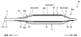
- a balloon catheter 50 according to a fifth embodiment of the present invention will be described with reference to FIGS.
- a difference from the balloon catheter 10 according to the first embodiment (see FIGS. 1 to 6 and the like) is that a linear member 45 is provided instead of the linear member 41 (see FIGS. 4 to 6 and the like).
- the linear member 45 includes linear members 45A and 45B.
- the linear members 45A and 45B correspond to the linear members 41A and 41B (see FIG. 7 and the like), respectively.
- the linear member 45 further includes a linear member (not shown) corresponding to the linear member 41C (see FIG. 7).
- the balloon body 50A corresponds to the balloon body 10A in the balloon catheter 10 (see FIGS. 1 to 6 and the like).
- the linear member 45 has a soft portion 451 and a hard portion 452.
- the flexible portion 451 extends between the proximal end of the proximal leg 31 and the distal end of the distal leg 35.
- the flexible portion 451 includes a first portion 451A, a second portion 451B, and a third portion 451C.
- the first portion 451A, the second portion 451B, and the third portion 451C correspond to respective portions obtained by dividing the soft portion 451 into three along the extending direction.
- the first portion 451 ⁇ / b> A is disposed on the outer peripheral surface 3 ⁇ / b> D of each of the proximal end leg portion 31 and the proximal end cone region 32 of the balloon 3.
- the second portion 451B is disposed on the outer peripheral surface 3D of the inflation region 33 of the balloon 3.
- the third portion 451C is disposed on the outer peripheral surface 3D of each of the tip-side cone region 34 and the tip-side leg portion 35 of the balloon 3.
- the hard portion 452 is stacked on a portion of the second portion 451B of the soft portion 451 opposite to the portion facing the balloon 3.
- the first portion 451A and the third portion 451C of the flexible portion 451 correspond to the proximal end portion 441 and the distal end portion 443 (see FIG. 11) of the linear member 44 in the balloon catheter 40, respectively.
- the second portion 451B and the hard portion 452 of the soft portion 451 correspond to the expanded portion 442 (see FIG. 11) of the linear member 44.
- FIG. 13 shows respective cross sections along the lines A1-A1, B1-B1, and C1-C1 of the linear member 45 in a state where no force in the extending direction is applied.
- the cross-sectional shape of the flexible portion 451 (the first portion 451A to the third portion 451C) is a trapezoid.
- the cross-sectional shape of the hard portion 452 is a portion (hereinafter referred to as “boundary portion 450B”) opposite to the portion facing the balloon 3 (hereinafter referred to as “inner portion 450A”) in the second portion 451B of the flexible portion 451. .) Is an equilateral triangle with one side.
- the rigid portion 452 protrudes outward from the boundary portion 450B.
- outer end portion of the rigid portion 452 is referred to as an “outer portion 450C”.
- a point corresponding to the vertex of the equilateral triangle in the outer portion 450C is referred to as a vertex 450D.
- the apex 450D is pointed.
- the linear member 45 is made of a polyamide resin. More specifically, the soft portion 451 is formed of a polyamide-based elastomer. The hardness of the flexible portion 451 is a value within the range of D25 to D63 according to ISO868.
- the hard part 452 is formed of a polyamide resin. The hardness of the hard portion 452 is a value within the range of D70 to D95 according to ISO868. That is, the hard part 452 is harder than the soft part 451.
- the soft part 451 is superior in stretchability compared to the hard part 452.
- each of the two notches 51 is formed by missing a part of the linear member 45.
- the cross-sectional shape of each notch 51 is a wedge shape.
- the two notches 51 are arranged at equal intervals in the extending direction.
- Each notch 51 has surfaces 51A and 51B facing each other in the extending direction.
- An inner end portion (hereinafter referred to as “bottom portion”) 51C of the notch 51 is located on the inner side of the boundary portion 450B between the second portion 451B and the hard portion 452 of the soft portion 451 in the radial direction.
- the balloon 3 When the balloon 3 is inflated in response to the supply of compressed fluid from the hub 5, the balloon 3 extends in the extending direction. For this reason, a force in the extending direction acts on the soft portion 451 of the linear member 45 that contacts the outer peripheral surface 3D of the balloon 3. In this case, the first portion 451A and the third portion 451C are elastically deformed so as to extend along the extending direction. A force in the stretching direction also acts on a portion of the linear member 45 where the second portion 451B12 of the flexible portion 451 and the hard portion 452 are laminated. Here, the hard portion 452 is less likely to be stretched than the soft portion 451.
- the portion of the linear member 45 where the second portion 451B of the soft portion 451 and the hard portion 452 are laminated is also elastically deformed so as to extend in the extending direction in accordance with the expansion of the balloon 3.
- the linear member 45 extends in the stretching direction following the expansion of the balloon 3 in the entire region in the stretching direction.
- the flexible portion 451 of the linear member 45 can be stretched. For this reason, when the linear member 45 is to be stretched in response to the expansion of the balloon 3, the first portion 451A and the third portion 451C in which the hard portion 452 is not laminated among the soft portions 451 are the balloon 3 Stretches well following the above. Two notches 51 are formed in the linear member 45. For this reason, when the second portion 451B of the flexible portion 451 tries to stretch in accordance with the expansion of the balloon 3, the surfaces 51A and 51B of the respective notches 51 are separated from each other. Thereby, it is suppressed that the extension of the second portion 451B of the soft portion 451 is inhibited by the hard portion 452. For this reason, the linear member 45 can be appropriately stretched over the entire region in accordance with the expansion of the balloon 3, and can follow the expansion of the balloon 3. Therefore, the balloon catheter 50 can suppress the linear member 45 from inhibiting the expansion of the balloon 3.
- the outer portion 450C of the rigid portion 452 of the linear member 45 protrudes outward with respect to the balloon 3.
- the hard part 452 is harder than the soft part 451. For this reason, when the balloon 3 is inflated, the linear member 45 can appropriately cause the rigid portion 452 to act on the blood vessel.
- the balloon catheter 50 when the balloon 3 is inflated, the surfaces 51A and 51B of the plurality of notches 51 are separated in the extending direction. Thereby, the second portion 451B of the soft portion 451 is elastically deformed satisfactorily.
- the strength of the linear member 45 itself may be reduced at the plurality of notches 51.
- the linear member 45 is entirely covered from the outside by the pressing member 6. For this reason, even when the linear member 45 is broken at the notch 51 due to the strength reduction, the linear member 45 is not detached from the balloon 3. As described above, the pressing member 6 can suppress the linear member 45 from being detached from the balloon 3 when the linear member 45 is broken at the notch 51.
- a balloon catheter 60 according to a sixth embodiment of the present invention will be described with reference to FIGS. 14 and 15.
- the linear member 46 of the balloon catheter 60 in the sixth embodiment has the same shape as the linear member 41 (see FIGS. 4 to 6 etc.) of the balloon catheter 10 (see FIGS. 1 to 6 etc.).
- the balloon catheter 60 is different from the balloon catheter 10 in that a part of the pressing member 6 is disposed between the outer peripheral surface 3D of the linear member 46 and the balloon 3, as shown in FIG.
- a portion of the pressing member 6 disposed between the outer peripheral surface 3D of the balloon 3 and the linear member 46 is referred to as a joint portion 63.
- the balloon body 60A corresponds to the balloon body 10A in the balloon catheter 10 (see FIG. 1 to FIG. 6 and the like).
- the pressing member 6 includes a first film part 61, a second film part 62, and a joint part 63.
- the joint 63 enters between the outer peripheral surface 3D of the balloon 3 and the linear member 46 when the pressing member 6 is formed in the manufacturing process of the balloon catheter 60, and the linear member 46 enters the outer peripheral surface 3D of the balloon 3.
- the pressing member 6 presses the linear member 46 against the balloon 3 by the first film portion 61 and the second film portion 62 and simultaneously bonds the linear member 46 to the balloon 3 by the bonding portion 63.
- the coating material constituting the pressing member 6 enters between the outer peripheral surface 3D of the balloon 3 and the linear member 46. When the material is dried, the balloon 3 and the linear member 46 are stuck. Thereby, the joining part 63 is formed. By providing the joint portion 63, friction between the balloon 3 and the linear member 46 increases. As the balloon 3 expands, the linear member 46 also extends.
- the linear member 46 is connected to the balloon 3 by the joint portion 63 of the pressing member 6.
- the outer peripheral surface 3D is joined.
- the balloon catheter 60 can further appropriately prevent the linear member 46 from being displaced with respect to the balloon 3.
- the balloon catheter 60 can prevent the displacement of the position of the linear member 46 relative to the balloon 3 by joining the linear member 46 to the outer peripheral surface 3D of the balloon 3 by the joining portion 63. Therefore, the balloon catheter 60 can cause the linear member 46 to act on the blood vessel when the balloon 3 is inflated while the linear member 46 is held at an appropriate position with respect to the balloon 3.
- the balloon body 10A includes (1) coating coating (see FIG. 16), (2) blow molding (see FIG. 17), (3) sticking of the pressing member 6 (see FIG. 18), and (4) the pressing member 6 It can be manufactured by a manufacturing method using heat shrinkability (see FIG. 19).
- a case where the balloon body 10A according to the first embodiment is manufactured will be described as an example, but the balloon bodies 20A (see FIG. 9), 30A (see FIG. 10) according to the second to sixth embodiments, 40A (see FIG. 11), 50A (see FIG.
- the above (1) to (4) only exemplify the manufacturing method of the balloon body 10A, and it goes without saying that the balloon body 10A can be manufactured by a manufacturing method other than (1) to (4).
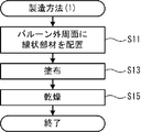
- the linear member 41 is arrange
- the linear member 41 is disposed on the outer peripheral surface 3D, and the coating application of the melt using spray is performed on the balloon 3 (S13). The coating time is optimized according to the thickness of the pressing member 6.
- the melt After completion of the coating, the melt is in a state of covering each of the balloon 3 and the linear member 41 from the outside by surface tension.
- the melt may enter not only the outer surfaces of the balloon 3 and the linear member 41 but also the gap between the balloon 3 and the linear member 41.
- the balloon 3 and the linear member 41 coated with the melt using spray are dried (S15).
- the temperature at this time is adjusted according to the characteristics of the melt.
- the melt covering the balloon 3 and the linear member 41 from the outside forms the first film portion 61 and the second film portion 62 of the pressing member 6 by drying.
- the first film portion 61 and the second film portion 62 of the pressing member 6 are in close contact with the linear member 41 and the balloon 3 and press the linear member 41 against the outer peripheral surface 3D of the balloon 3.
- the melt that has entered the gap between the balloon 3 and the linear member 41 forms a joint 63 of the pressing member 6 by drying.
- the joining portion 63 of the pressing member 6 joins the linear member 41 to the balloon 3.
- the linear member 41 is firmly pressed against the outer peripheral surface 3D of the balloon 3 by the first film portion 61 and the second film portion 62 of the pressing member 6.
- the joint portion 63 is formed, the linear member 41 is directly joined to the outer peripheral surface 3D of the balloon 3 by the joint portion 63.
- Application coating using a spray is generally known as a production method capable of relatively easily forming a thin film that adheres to an uneven surface. For this reason, according to the manufacturing method of (1), 10 A of balloon bodies in which the linear member 41 cannot shift easily with respect to the outer peripheral surface 3D of the balloon 3 can be manufactured easily.
- the method of coating the melt is not limited to the application coating using a spray, and may be another known coating method.
- the melt may be coated on the balloon 3 and the linear member 41 based on the dip coating method.
- the melt may be coated on the balloon 3 and the linear member 41 using a tool such as a brush.
- a pair of molds (male and female) for blow molding having an inner wall of the same shape as the inflated balloon 3 is prepared.
- a film-like pressing member 6 is disposed along each inner wall of the set of molds (S21).
- the linear member 41 is arrange
- an adhesive or the like may be used to temporarily hold the positional relationship between the balloon 3 and the linear member 41.
- a set of molds is assembled.
- the parison is injected into the assembled mold (S25).
- the parison is a cylindrical material that is the basis of the balloon 3, and is constituted by the raw material of the balloon 3.
- a parison is inject
- the linear member 41 is sandwiched between the parison and the pressing member 6.
- the mold is opened, and the balloon 3, the linear member 41, and the pressing member 6 are taken out.
- the taken-out balloon 3, the linear member 41, and the pressing member 6 are cooled (S29). Thereby, the balloon body 10A is formed.
- the pressing member 6 presses the linear member 41 against the outer peripheral surface 3D of the balloon 3.
- the linear member 41 is firmly pressed against the outer peripheral surface 3D of the balloon 3 by the pressing member 6, so that the linear member 41 can be brought into close contact with the balloon 3 by the pressing member 6.
- the solid pressing member 6 can be used as it is without being liquefied, and the balloon body 10A can be manufactured. For this reason, it can suppress that the physical property of the press member 6 changes by the state of the press member 6 changing at the time of manufacture.
- an adhesive may be used to temporarily hold the positional relationship between the balloon 3 and the linear member 41.
- the linear member 41 can be attached to the balloon 3 using an adhesive for attaching the pressing member 6 to the balloon 3 and the linear member 41.
- the outer peripheral surface 3D of the balloon 3, the pressing member 6, and the linear member 41 can be joined using a common adhesive.
- the linear member 41 is arranged on the outer peripheral surface 3D of the balloon 3 (S41).
- a film-like pressing member 6 having heat shrinkability is prepared.
- the outer peripheral surface 3D of the balloon 3 and the outer surface of the linear member 41 are covered from the outside by the pressing member 6 (S43).
- the pressing member 6 is heated (S45).
- the pressing member 6 contracts inward.
- the pressing member 6 is in close contact with the outer peripheral surface 3D of the balloon 3 and the linear member 41 from the outside.
- the linear member 41 is pressed against the balloon 3 by the pressing member 6.
- heating of the pressing member 6 is stopped, and the pressing member 6 is cooled (S47).
- the linear member 41 is sandwiched between the balloon 3 and the pressing member 6.
- the linear member 41 is firmly pressed against the outer peripheral surface 3D of the balloon 3 by the pressing member 6, so that the linear member 41 can be brought into close contact with the balloon 3 by the pressing member 6. Since the dry manufacturing method is the same as the manufacturing method of (3), the balloon body 10A can be easily manufactured without requiring large-scale equipment. Unlike the manufacturing method (3), an adhesive for adhering the pressing member 6 becomes unnecessary. For this reason, 10 A of balloon bodies can be manufactured still more easily than the manufacturing method of (3).
- the catheter shaft 2 may not have the outer tube 21 and the inner tube 22.
- the catheter shaft 2 may have only one flexible tube.
- the number of each of the linear members 41 to 46 is not limited to three, and may be other numbers.
- the cross-sectional shape of each of the linear members 41 to 46 may not be an equilateral triangle, and may be, for example, an isosceles triangle or a triangle having three sides having different lengths.
- the linear members 41 to 46 may have a function as a cutting blade for incising a lesioned part in a state where the balloon 3 is inflated.
- the boundary portion between the proximal end cone region 32 and the inflation region 33 of the inflated balloon 3 and the boundary portion between the inflation region 33 and the distal cone region 34 may be curved.
- the diameters of the proximal-side cone region 32 and the distal-side cone region 34 change linearly from the proximal side toward the distal side.
- the diameters of the proximal-side cone region 32 and the distal-side cone region 34 may change in a curve from the proximal side toward the distal side.
- One of the proximal cone region 32 and the distal cone region 34 may change in diameter in a curved manner, and the other may change in diameter in a linear manner.
- the markers 22 ⁇ / b> A and 22 ⁇ / b> B may not be provided on the inner tube 22.
- the linear members 41 to 46 may extend spirally along the extending direction. Of the linear members 41 to 45, part or all of the portions facing the outer peripheral surface 3D of the inflation region 33 of the balloon 3 may be joined to the outer peripheral surface 3D of the balloon 3.
- the joining method at this time is not limited, and may be any one of joining with an adhesive, welding, fusion, and the like.
- the pressing member 6 may cover only a part of the outer peripheral surface 3D of the balloon 3.
- the pressing member 6 may cover only the outer peripheral surface 3 ⁇ / b> D of the inflation region 33 of the balloon 3.
- the pressing member 6 may cover only the vicinity of the portion where the linear members 41 to 46 are arranged on the outer peripheral surface 3D of the inflation region 33 of the balloon 3.
- the linear members 41 to 46 are not covered by the pressing member 6 and are exposed.
- the shape of the pressing member 6 is not limited to a film shape.
- the inner diameter of the pressing member 6 in a state where no force is applied to the pressing member 6 may be smaller than the outer diameter of the expanded balloon 6. In this case, since the elastic force of the pressing member 6 acts in a direction in which the expanded balloon 6 is contracted, the linear member 41 is pressed against the balloon 6.
- the linear members 41 to 46 are outer peripheral surfaces 3D of portions excluding the inflation region 33 of the balloon 3 (base end side leg portion 31, base end side cone region 32, tip end side cone region 34, and tip end side leg portion 35). It may be arranged only in
- the proximal end of the linear member 43 may be directly joined to the outer tube 21 without the attachment member 21A.
- the end of the linear member 44 on the distal end side may be joined to the outer peripheral surface 224 of the protruding portion 225 (see FIGS. 4 and 6) of the inner tube 22.
- the proximal end of the linear member 43 may be joined to the proximal leg 31 of the balloon 3.
- the end on the distal end side of the linear member 43 may be joined to the distal leg portion 35 of the balloon 3.
- the bottom 51C see FIG.
- the notch 51 may be located at substantially the same position as the boundary portion 450B in the radial direction, or located outside the boundary portion 450B. May be.
- an incision may be formed instead of the notch 51.
- the notch is different from the notch 51 in that the two surfaces facing in the extending direction are in contact with each other in a state where the balloon 3 is not inflated.
- the position of the bottom of the cut may be any position inside the boundary portion 450B, substantially the same position as the boundary portion 450B, and outside the boundary portion 450B in the radial direction.
- the linear member 45 may not have both the notch 51 and the notch.
Landscapes
- Health & Medical Sciences (AREA)
- Life Sciences & Earth Sciences (AREA)
- Heart & Thoracic Surgery (AREA)
- Engineering & Computer Science (AREA)
- Biomedical Technology (AREA)
- Veterinary Medicine (AREA)
- Public Health (AREA)
- General Health & Medical Sciences (AREA)
- Animal Behavior & Ethology (AREA)
- Hematology (AREA)
- Anesthesiology (AREA)
- Pulmonology (AREA)
- Biophysics (AREA)
- Child & Adolescent Psychology (AREA)
- Vascular Medicine (AREA)
- Surgery (AREA)
- Nuclear Medicine, Radiotherapy & Molecular Imaging (AREA)
- Manufacturing & Machinery (AREA)
- Medical Informatics (AREA)
- Molecular Biology (AREA)
- Media Introduction/Drainage Providing Device (AREA)
- Mechanical Engineering (AREA)
- Materials For Medical Uses (AREA)
Abstract
バルーンカテーテル(10)は、基端から先端に向けて延伸方向に延びるカテーテルシャフト(2)、カテーテルシャフト(2)に設けられ、カテーテルシャフト(2)を中心とする半径方向の外側に膨張可能なバルーン(3)、バルーン3の外周面(3D)の少なくとも一部分に配置され、延伸方向に沿って延びる線状部材(41)、線状部材(41)をバルーンに押し付ける押圧部材(6)を備えている。線状部材(41)は、バルーン(3)のうち、膨張時において径が略一定となる膨張領域(33)に配置される。
Description
本発明は、バルーンカテーテル、及び、バルーン体の製造方法に関する。
血管の狭窄した箇所を拡張する治療に使用されるバルーンカテーテルが知られている。線状部材をバルーンの表面に有するバルーンカテーテルが提案されている。線状部材は、バルーンが拡張した状態で血管に作用する。例えば、バルーンの拡張によって線状部材が血管の病変部に食い込んだ場合、病変部に対してバルーンを滑りにくくできる。このため、バルーンカテーテルは、バルーンの膨張によって病変部を血管の内側から適切に拡張できる。
特許文献1は、線状部材として複数のウィングを有するバルーンを備えたバルーンカテーテルを開示する。複数のウィングは、バルーンよりも相対的に硬い。複数のウィングは、バルーンの膨張時に半径方向外側に延びる。このため、複数のウィングは、バルーンの膨張によって血管の組織に高い圧力を及ぼす。バルーンに対する複数のウィングの成形方法として、2つの方法が例示されている。1つ目は、バルーンの一部を複数のウィングとして成形する方法である。2つ目は、バルーンとは別の材料を溶接、接着、融着等によってバルーンに取り付ける方法である。
バルーンとは別材料の線状部材がバルーンに接合される場合、バルーンの膨張に応じて線状部材がバルーンから脱離し易い。線状部材がバルーンから脱離した場合、線状部材の位置が所望の位置からずれる可能性がある。線状部材がバルーンに接合されていない場合、バルーンの膨張に応じて線状部材の位置が所望の位置からずれる可能性がある。これらのように、少なくとも一部がバルーン外周面上に配置された線状部材の位置が、バルーンの膨張に応じて所望の位置からずれ得る。
本発明の目的は、バルーンが膨張した場合に線状部材がバルーンの所望の位置に対して位置ずれし難いバルーンカテーテル、及び、バルーン体の製造方法を提供することである。
本発明の第1態様に係るバルーンカテーテルは、基端から先端に向けて延伸方向に延びるカテーテルシャフトと、前記カテーテルシャフトに設けられ、前記カテーテルシャフトを中心とする半径方向の外側に膨張可能なバルーンと、前記バルーンの外周面の少なくとも一部分に配置され、前記延伸方向に沿って延びる線状部材と、前記線状部材を前記バルーンに押し付ける押圧部材とを備えたことを特徴とする。
第1態様において、バルーンカテーテルは、線状部材をバルーンに押し付ける押圧部材を有する。このため、バルーンカテーテルは、溶接、接着、融着等によってバルーンに線状部材が取り付けられる場合と比べて、バルーンの膨張時において線状部材がバルーンに対して位置ずれすることを抑制できる。
第1態様において、前記押圧部材は、前記バルーンの前記外周面の少なくとも一部を覆う膜部を有し、前記線状部材の少なくとも一部は、前記膜部と前記バルーンとの間に配置されてもよい。この場合、バルーンカテーテルは、膜部によって線状部材をバルーンに押し付けることによって、線状部材がバルーンに対して位置ずれすることを抑制できる。バルーンカテーテルは、線状部材をバルーンに押し付ける押圧部材を膜状とすることによって、バルーン全体の径が押圧部材によって拡張されることを抑制できる。従って、バルーンカテーテルは、血管内をバルーンが移動するときに押圧部材が血管の内壁に引っ掛かることを抑制できる。このため、バルーンカテーテルは、バルーンの通過性が低下することを抑制できる。
第1態様において、前記膜部は、前記バルーンの前記外周面の全体を覆ってもよい。この場合、バルーンカテーテルは、バルーン全体を膜部で覆うことによって、バルーンが膨張した場合における線状部材の位置ずれを更に適切に抑制できる。
第1態様において、前記線状部材は、前記バルーンの前記外周面のうち膨張領域に少なくとも配置され、前記膨張領域は、前記バルーンのうち前記延伸方向に亘って延びる一部の領域であって、前記延伸方向に沿って径が略一定の領域であってもよい。この場合、バルーンカテーテルは、径が略一定である膨張領域で線状部材を血管に適切に作用させることができる。
第1態様において、前記線状部材は、前記バルーンの前記膨張領域に配置された膨張部分と、前記膨張領域に対して前記先端側に位置する先端部分、及び、前記膨張領域に対して前記基端側に位置する基端部分の少なくとも一方とを備えてもよい。この場合、バルーンカテーテルは、線状部材が膨張部分のみ有する場合と比べて、バルーンの外周面と線状部材との接触面積を大きくできる。このため、バルーンカテーテルは、線状部材とバルーンとの接触部分によって線状部材の位置ずれが抑制される場合、接触面積を大きくすることで線状部材の位置ずれを適切に抑制できる。
第1態様において、前記線状部材のうち、前記バルーンと対向する内側部分と反対側に配置する外側部分が、前記バルーンよりも硬くてもよい。この場合、バルーンカテーテルは、バルーンの膨張時において線状部材を血管に適切に作用させることができる。
第1態様において、前記線状部材は、前記内側部分を少なくとも含み、延伸可能な軟性部分と、前記外側部分を少なくとも含み、前記軟性部分よりも硬さが高い硬性部分とを有してもよい。この場合、線状部材の硬性部分は、軟性部分よりも硬さが硬いので、線状部材は、バルーンの膨張時に硬性部分を血管に適切に作用させることができる。線状部材の軟性部分は延伸可能である。このため、バルーンカテーテルは、バルーンの膨張に応じて軟性部分が延伸することによって、バルーンの膨張に線状部材を追従させることができる。従って、バルーンカテーテルは、バルーンの膨張時に線状部材がバルーンに対して位置ずれしたり、線状部材がバルーンの膨張を阻害したりすることを抑制できる。
第1態様において、前記線状部材の少なくとも一部が前記バルーンに接合されてもよい。この場合、押圧部材によって線状部材がバルーンに押し付けられることに加えて、線状部材がバルーンに直接接合される。このため、バルーンカテーテルは、線状部材がバルーンに対して位置ずれすることを更に適切に抑制できる。
第1態様において、前記押圧部材は、前記バルーンと前記線状部材との間に配置された接合部を有し、前記線状部材は、前記接合部によって前記バルーンに接合されてもよい。この場合、押圧部材は、線状部材をバルーンに押し付けると同時に、接合部によって線状部材をバルーンに直接接合できる。
第1態様において、前記線状部材の前記先端側の端部及び前記基端側の端部の少なくとも一方が、前記カテーテルシャフトに接合されてもよい。この場合、バルーンカテーテルは、線状部材がバルーンに対して位置ずれすることを押圧部材によって抑制できると同時に、線状部材がカテーテルシャフトに対して位置ずれすることを抑制できる。
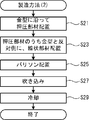
本発明の第2態様に係るバルーン体の製造方法は、第1態様に係る前記バルーン、前記線状部材、及び、前記押圧部材を含むバルーン体を製造する製造方法であって、前記バルーンの前記外周面に前記線状部材を配置させる工程と、前記押圧部材の材料を溶融した溶融体を、前記線状部材が前記外周面に配置された状態の前記バルーンに塗布する工程と、塗布後、前記バルーン及び前記線状部材に付着した前記溶融体を乾燥して前記押圧部材を形成する工程とを備えている。この場合、線状部材は、押圧部材によってバルーンの外周面に強固に押し付けられる。従って、バルーンに対して線状部材が位置ずれし難いバルーン体を容易に製造できる。
本発明の第3態様に係るバルーン体の製造方法は、第1態様に係る前記バルーン、前記線状部材、及び、前記押圧部材を含むバルーン体を製造する製造方法であって、金型の内壁に沿って前記押圧部材を配置させる工程と、前記押圧部材に対して前記金型と反対側に、前記線状部材を配置させる工程と、前記線状部材に対して前記押圧部材と反対側に、前記バルーンの基となるパリソンを吐出する工程と、前記パリソンの内部に空気を吹き込む工程とを備え、前記パリソンの内部に空気が吹き込まれることによって、前記金型に前記パリソンが押し付けられて前記バルーンが成形され、且つ、前記押圧部材及び前記線状部材が前記バルーンに密着することを特徴とする。この場合、線状部材は、押圧部材によってバルーンの外周面に強固に押し付けられる。従って、バルーンに対して線状部材が位置ずれし難いバルーン体を製造できる。固体状の押圧部材をそのまま使用してバルーン体を製造できる。従って、押圧部材の状態が製造時に変化することによって押圧部材の物性が変化することを抑制できる。
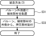
本発明の第4態様に係るバルーン体の製造方法は、第1態様に係る前記バルーン、前記線状部材、及び、前記押圧部材を含むバルーン体を製造する製造方法であって、前記バルーンの前記外周面に前記線状部材を配置させる工程と、膜状の前記押圧部材によって、前記線状部材の前記外側から前記線状部材の少なくとも一部を覆い、且つ、前記押圧部材を前記外周面に貼付する工程とを備えている。この場合、バルーンの外周面に線状部材が押圧部材によって押し付けられたバルーン体を、容易に製造できる。
本発明の第5態様に係るバルーン体の製造方法は、第1態様に係る前記バルーン、前記線状部材、及び、前記押圧部材を含むバルーン体を製造する製造方法であって、前記バルーンの前記外周面に前記線状部材を配置させる工程と、熱収縮性を有する前記押圧部材によって、前記線状部材の前記外側から前記線状部材を覆う工程と、前記線状部材が前記押圧部材によって覆われた状態で、前記押圧部材を加熱し、前記押圧部材を収縮させる工程とを備えている。この場合、バルーン及び線状部材に押圧部材を密着させることができる。乾式の製造方法である為、大規模な設備を要することなく容易にバルーン体を製造できる。
<第1実施形態(バルーンカテーテル10)>
以下、本発明の第1実施形態に係るバルーンカテーテル10について、図1~図8を参照して説明する。図1に示すように、バルーンカテーテル10は、カテーテルシャフト2、バルーン3、線状部材41A、41B、41C(図3等参照。以下、総称して「線状部材41」という。)、及び、押圧部材6を有する。バルーン3は、カテーテルシャフト2の一方側の端部に接続される。以下、カテーテルシャフト2の両端のうち一方側の端を、「先端」という。カテーテルシャフト2の両端のうち他方側の端を、「基端」という。線状部材41は、バルーン3の外周面3D(図2参照)上に位置する。押圧部材6は、バルーン3及び線状部材41を覆い、バルーン3に線状部材41を押し付ける。以下、バルーン3、線状部材41、及び、押圧部材6を、「バルーン体10A」という。
以下、本発明の第1実施形態に係るバルーンカテーテル10について、図1~図8を参照して説明する。図1に示すように、バルーンカテーテル10は、カテーテルシャフト2、バルーン3、線状部材41A、41B、41C(図3等参照。以下、総称して「線状部材41」という。)、及び、押圧部材6を有する。バルーン3は、カテーテルシャフト2の一方側の端部に接続される。以下、カテーテルシャフト2の両端のうち一方側の端を、「先端」という。カテーテルシャフト2の両端のうち他方側の端を、「基端」という。線状部材41は、バルーン3の外周面3D(図2参照)上に位置する。押圧部材6は、バルーン3及び線状部材41を覆い、バルーン3に線状部材41を押し付ける。以下、バルーン3、線状部材41、及び、押圧部材6を、「バルーン体10A」という。
バルーンカテーテル10は、カテーテルシャフト2の基端にハブ5が接続された状態で使用される。ハブ5は、カテーテルシャフト2を介してバルーン3に圧縮流体を供給可能である。カテーテルシャフト2に沿って延びる方向を、「延伸方向」という。延伸方向と直交する平面上において、カテーテルシャフト2の断面中心を基準とする半径方向のうち、カテーテルシャフト2の断面中心に近接する側を「内側」といい、カテーテルシャフト2の断面中心から離隔する側を「外側」という。
<カテーテルシャフト2>
図4、図6に示すように、カテーテルシャフト2は、外側チューブ21及び内側チューブ22を有する。外側チューブ21及び内側チューブ22は、それぞれ、可撓性を有する管状の部材である。外側チューブ21は、内側の面である内面212で囲まれた空間である内腔213を有する。内側チューブ22は、内側の面である内面222で囲まれた空間である内腔223を有する。外側チューブ21及び内側チューブ22は、ポリアミド系樹脂により形成される。外側チューブ21の内径は、内側チューブ22の外径よりも大きい。
図4、図6に示すように、カテーテルシャフト2は、外側チューブ21及び内側チューブ22を有する。外側チューブ21及び内側チューブ22は、それぞれ、可撓性を有する管状の部材である。外側チューブ21は、内側の面である内面212で囲まれた空間である内腔213を有する。内側チューブ22は、内側の面である内面222で囲まれた空間である内腔223を有する。外側チューブ21及び内側チューブ22は、ポリアミド系樹脂により形成される。外側チューブ21の内径は、内側チューブ22の外径よりも大きい。
内側チューブ22は、先端側の所定部分を除き、外側チューブ21の内腔213内に配置される。内側チューブ22の先端側の所定部分は、外側チューブ21の先端側の端(以下、「先端211」という。)から先端側に向けて突出する。このため、内側チューブ22の先端側の端(以下、「先端221」という。)は、外側チューブ21の先端211よりも先端側に配置される。以下、内側チューブ22の先端側の所定部分を、「突出部分225」という。内側チューブ22の突出部分225に、放射線不透過マーカ(以下、単に「マーカ」という。)22A、22Bが装着される。マーカ22A、22Bの材料として、放射線不透過材が混合された樹脂が用いられる。マーカ22A、22Bは、上記の材料で形成された円筒部材が内側チューブ22の突出部分225にかしめられることによって、内側チューブ22の突出部分225の外周面224に固定される。マーカ22A、22Bは、延伸方向において所定長さを有する。マーカ22A、22Bは、放射線を透過させない。マーカ22Aは、マーカ22Bよりも先端側に配置される。マーカ22A、22Bは、延伸方向に離隔する。
外側チューブ21の内腔213のうち、内側チューブ22の内腔223以外の空間には、ハブ5(図1参照)から供給される圧縮流体が通流する。バルーン3は、圧縮流体の供給に応じて膨張する(図5~図8参照)。内側チューブ22の内腔223には、図示しないガイドワイヤが挿通される。
外側チューブ21及び内側チューブ22の材料は、ポリアミド系樹脂に限定されず、可撓性を有する他の材料に変更可能である。例えば、外側チューブ21及び内側チューブ22の材料として、ポリエチレン系樹脂、ポリプロピレン系樹脂、ポリウレタン系樹脂、ポリイミド系樹脂などの合成樹脂材料が用いられてもよい。合成樹脂材料に添加剤が混合されてもよい。外側チューブ21及び内側チューブ22の材料として、それぞれ異なる合成樹脂材料が用いられてもよい。マーカ22A、22Bの材料は、放射線不透過材が混合された樹脂に限定されず、放射線を通過させない他の材料に変更可能である。例えば、マーカ22A、22Bの材料として、放射線不透過材が蒸着された樹脂、又は、金属等の放射線を透過しない材料等が用いられてもよい。
<バルーン3>
バルーン3は、図2~図4に示すように、圧縮流体が供給されない状態で、内側に収縮する。一方、バルーン3は、図5~図8に示すように、圧縮流体が供給された状態で、外側に膨張する。バルーン3は、ポリアミド系樹脂により形成されている。図2、図4~図6に示すように、バルーン3は、基端側レッグ部31、基端側コーン領域32、膨張領域33、先端側コーン領域34、及び、先端側レッグ部35を有する。基端側レッグ部31、基端側コーン領域32、膨張領域33、先端側コーン領域34、及び、先端側レッグ部35は、延伸方向に沿ってバルーン3を5分割したそれぞれの部分に対応する。膨張領域33の延伸方向の長さは、基端側レッグ部31、基端側コーン領域32、先端側コーン領域34、及び、先端側レッグ部35のそれぞれの延伸方向の長さよりも長い。
バルーン3は、図2~図4に示すように、圧縮流体が供給されない状態で、内側に収縮する。一方、バルーン3は、図5~図8に示すように、圧縮流体が供給された状態で、外側に膨張する。バルーン3は、ポリアミド系樹脂により形成されている。図2、図4~図6に示すように、バルーン3は、基端側レッグ部31、基端側コーン領域32、膨張領域33、先端側コーン領域34、及び、先端側レッグ部35を有する。基端側レッグ部31、基端側コーン領域32、膨張領域33、先端側コーン領域34、及び、先端側レッグ部35は、延伸方向に沿ってバルーン3を5分割したそれぞれの部分に対応する。膨張領域33の延伸方向の長さは、基端側レッグ部31、基端側コーン領域32、先端側コーン領域34、及び、先端側レッグ部35のそれぞれの延伸方向の長さよりも長い。
図4、図6に示すように、基端側レッグ部31は、外側チューブ21の外周面214のうち、先端211よりも基端側の部分に、熱溶着によって接続される。基端側コーン領域32は、基端側レッグ部31に対して先端側に隣接する。膨張領域33は、基端側コーン領域32に対して先端側に隣接する。先端側コーン領域34は、膨張領域33に対して先端側に隣接する。先端側レッグ部35は、先端側コーン領域34に対して先端側に隣接する。先端側レッグ部35は、内側チューブ22の突出部分225の外周面224のうち、先端221よりも基端側の部分に、熱溶着によって接続される。基端側レッグ部31、基端側コーン領域32、膨張領域33、先端側コーン領域34、及び、先端側レッグ部35は、基端側から先端側に向けて順番に並ぶ。基端側コーン領域32、膨張領域33、先端側コーン領域34、及び、先端側レッグ部35は、内側チューブ22の突出部分225を外側から覆う。
図2~図4に示すように、バルーン3は、収縮した状態で3枚の羽根が形成される、3枚羽式のバルーンである。図3に示すように、バルーン3は、収縮した状態において、羽3A、3B、3Cが形成されるように折畳まれる。羽3A、3B、3Cは、内側チューブ22の突出部分225の周囲に巻きつく。この状態で、羽3Aは、後述する線状部材41Aを外側から覆う。羽3Bは、後述する線状部材41Bを外側から覆う。羽3Cは、後述する線状部材41Cを外側から覆う。羽3A、3B、3Cは、「フラップ」「ウイング」とも呼ばれる。
図5~図7を参照し、膨張した状態のバルーン3について説明する。図7に示すように、バルーン3の断面形状は円形である。図5、図6に示すように、基端側コーン領域32はテーパ形状を有する。基端側コーン領域32は、基端側から先端側に向けて連続的且つ直線的に直径が大きくなる。膨張領域33は延伸方向に延びる。膨張領域33の径は、延伸方向の全域に亘って略一定となる。先端側コーン領域34はテーパ形状を有する。先端側コーン領域34は、基端側から先端側に向けて連続的且つ直線的に直径が小さくなる。バルーン3の断面の直径は、基端側コーン領域32、膨張領域33、及び、先端側コーン領域34の間で段階的に変化する。膨張領域33は、バルーン3における最大の外径部分となる。
図6に示すように、膨張領域33の先端側の境界、言い換えれば、膨張領域33と先端側コーン領域34との境界の位置は、延伸方向において、マーカ22Aの先端側の端部の位置P11と一致する。膨張領域33の基端側の境界、言い換えれば、膨張領域33と基端側コーン領域32との境界の位置は、延伸方向において、マーカ22Bの基端側の端部の位置P21と一致する。
バルーン3の材料は、ポリアミド系樹脂に限定されず、可撓性を有する他の材料に変更可能である。例えば、バルーン3の材料として、ポリエチレン系樹脂、ポリプロピレン系樹脂、ポリウレタン系樹脂、ポリイミド系樹脂、シリコンゴム、天然ゴムなどが用いられてもよい。外側チューブ21及び内側チューブ22とバルーン3との接続方法、及び、外側チューブ21と装着部材21Aとの接続方法は、熱溶着に限定されない。例えば、それぞれは接着剤によって接続されてもよい。
<線状部材41>
図4~図8を参照し、線状部材41について説明する。線状部材41は、曲げ変形に対して復元力を有する、モノフィラメント状の弾性体である。線状部材41A、41B、41Cは同一形状である。線状部材41は延伸方向に沿って延びる。
図4~図8を参照し、線状部材41について説明する。線状部材41は、曲げ変形に対して復元力を有する、モノフィラメント状の弾性体である。線状部材41A、41B、41Cは同一形状である。線状部材41は延伸方向に沿って延びる。
図4~図7に示すように、線状部材41は、バルーン3の膨張領域33の外周面3D(図5、図7参照)上に配置される。線状部材41は、後述する押圧部材6によってバルーン3に押し付けられる。線状部材41のうち、バルーン3と対向する部分(以下、「内側部分410」(図8参照)という。)は、バルーン3の外周面3Dに接触する。線状部材41はバルーン3の外周面3Dに対して移動可能である。バルーン3の外周面3Dに内側部分410は接合されない。線状部材41の基端側の端部の位置は、膨張領域33と基端側コーン領域32との境界位置と略一致する。線状部材41の先端側の端部の位置は、膨張領域33と先端側コーン領域34との境界位置と略一致する。線状部材41は、バルーン3の基端側レッグ部31、基端側コーン領域32、先端側コーン領域34、及び、先端側レッグ部35のそれぞれの外周面3D上には配置されない。
図7に示すように、バルーン3が膨張した状態において、線状部材41A、41B、41Cは、バルーン3を周方向に略3等分したそれぞれの位置で、延伸方向に直線状に延びる。図8に示すように、線状部材41の断面の形状は、内側部分410を底辺とする正三角形である。線状部材41のうち、内側部分410と対向する外側部分411の最も外側の部分、つまり、図8における正三角形の頂点部分412は尖っている。
線状部材41は、ポリアミド系樹脂によって形成されている。線状部材41の硬度は、ISO868にてD70~D95の範囲内の値となる。線状部材41は、内側部分410から外側部分411の全域に亘って、バルーン3よりも硬さが硬くなる。この場合、線状部材41は、バルーン3よりも延伸方向に伸縮し難くなる。本発明において、バルーン3は線状部材41よりも硬さが硬くてもよい。線状部材41は、バルーン3よりも延伸方向に良好に伸縮可能であってもよい。
<押圧部材6>
図4~図8に示すように、押圧部材6は、バルーン3全体を覆う膜状の部材である。押圧部材6は、バルーン3の外周面3D全体、より詳細には、バルーン3の基端側レッグ部31、基端側コーン領域32、膨張領域33、先端側コーン領域34、及び、先端側レッグ部35のそれぞれの外周面3Dの全てを覆う。
図4~図8に示すように、押圧部材6は、バルーン3全体を覆う膜状の部材である。押圧部材6は、バルーン3の外周面3D全体、より詳細には、バルーン3の基端側レッグ部31、基端側コーン領域32、膨張領域33、先端側コーン領域34、及び、先端側レッグ部35のそれぞれの外周面3Dの全てを覆う。
図8に示すように、押圧部材6は第1膜部61と第2膜部62とを含む。第1膜部61は、押圧部材6のうち、線状部材41に接触して線状部材41を外側から直接覆う部分である。第1膜部61は、バルーン3の外周面3Dとの間に線状部材41を挟む。第1膜部61は、線状部材41の外側部分411に密着する。第2膜部62は、押圧部材6のうち、バルーン3の外周面3Dに接触して外周面3Dを外側から直接覆う部分である。第2膜部62は、バルーン3の外周面3Dに密着する。線状部材41の外側部分411と第1膜部61との間、及び、バルーン3の外周面3Dと第2膜部62との間に隙間は形成されない。線状部材41は、押圧部材6の弾性によってバルーン3側に押し付けられる。このため、バルーン3に対する線状部材41の移動は、押圧部材6によって抑制される。なお、押圧部材6が線状部材41をバルーン3側に押し付ける力は、バルーン6が拡張した状態において、線状部材41がバルーン6から離間しない程度の力であればよい。そのため例えば、押圧部材6は、線状部材41および拡張したバルーン6の外周に沿って位置する弾性部材であればよい。具体的には、押圧部材6は、押圧部材6に対して力が作用していない状態において、線状部材41および拡張したバルーン6の外表面に沿った形状であればよい。この場合、線状部材41が拡張したバルーン6に対して移動することが押圧部材6によって抑制される。
ハブ5から圧縮流体が供給されることに応じてバルーン3が膨張した場合、バルーン3の膨張領域33は延伸方向に延びる。前述のように、線状部材41の内側部分410はバルーン3に接合されていない。線状部材41は、バルーン3よりも延伸方向に伸縮し難い。このため、バルーン3が伸長した場合、バルーン3の外周面3Dに対して線状部材41の内側部分410は延伸方向に摺動する。バルーン3の膨張領域33の伸長は、線状部材41によって妨げられない。バルーン3の外周面3Dに対する線状部材41の周方向の移動は、押圧部材6によって抑制される。このため、バルーン3の膨張時、線状部材41の周方向の移動は、押圧部材6によって抑制される。
一方、膨張した状態のバルーン3から圧縮流体が排出されることに応じてバルーン3が収縮する場合、延伸方向に延びた状態のバルーン3の膨張領域33は、復元力によって縮む。この場合も、バルーン3の膨張時と同様、バルーン3の外周面3Dに対して線状部材41の内側部分410は摺動する。このため、バルーン3の膨張領域33の収縮は、線状部材41によって妨げられない。バルーン3の膨張領域33はスムーズに収縮し、バルーン3に対する皺等の発生は抑制される。線状部材41Aは羽3Aによって外側から覆われ、線状部材41Bは羽3Bによって外側から覆われ、線状部材41Cは羽3Cによって外側から覆われる(図3参照)。例えば、押圧部材6の材料は、ポリエチレン系樹脂、ポリプロピレン系樹脂、ポリウレタン系樹脂、ポリイミド系樹脂、シリコンゴム、天然ゴムなどである。例えば、押圧部材6の厚みは5~40μmである。
<第1実施形態の作用、効果>
以上説明したように、バルーンカテーテル10は、線状部材41をバルーン3に押し付ける押圧部材6を有する。このため、バルーンカテーテル10は、溶接、接着、融着等によってバルーン3に線状部材41が取り付けられる場合と比べて、バルーン3の膨張時において線状部材41がバルーン3に対して位置ずれすることを抑制できる。線状部材41は、バルーン3に直接取り付けられないので、バルーン3の膨張時、膨張領域33の外周面3Dの伸長を妨げない。線状部材41がバルーン3の膨張を妨げる場合、バルーン3は延伸方向と交差する方向に曲折する可能性があり、好ましくない。これに対し、バルーンカテーテル10では、バルーン3の膨張が線状部材41によって抑制され難いので、バルーン3が膨張時に曲折することを防止できる。バルーンカテーテル10は、バルーン3の収縮時、バルーン3に皺等が発生することを防止できる。
以上説明したように、バルーンカテーテル10は、線状部材41をバルーン3に押し付ける押圧部材6を有する。このため、バルーンカテーテル10は、溶接、接着、融着等によってバルーン3に線状部材41が取り付けられる場合と比べて、バルーン3の膨張時において線状部材41がバルーン3に対して位置ずれすることを抑制できる。線状部材41は、バルーン3に直接取り付けられないので、バルーン3の膨張時、膨張領域33の外周面3Dの伸長を妨げない。線状部材41がバルーン3の膨張を妨げる場合、バルーン3は延伸方向と交差する方向に曲折する可能性があり、好ましくない。これに対し、バルーンカテーテル10では、バルーン3の膨張が線状部材41によって抑制され難いので、バルーン3が膨張時に曲折することを防止できる。バルーンカテーテル10は、バルーン3の収縮時、バルーン3に皺等が発生することを防止できる。
押圧部材6は、バルーン3の基端側レッグ部31、基端側コーン領域32、膨張領域33、先端側コーン領域34、及び、先端側レッグ部35のそれぞれの外周面3Dの全てを覆う。バルーン3及び線状部材41と押圧部材6とは隙間なく密着する。このため、押圧部材6は、線状部材41全体をバルーン3に押し付けることができるので、線状部材41がバルーン3に対して位置ずれすることを抑制できる。バルーンカテーテル10は、押圧部材6を膜状とすることによって、バルーン体10Aの径が押圧部材6によって拡張されることを抑制できる。従って、バルーンカテーテル10は、血管内をバルーン体10Aが移動するときに押圧部材6が血管の内壁に引っ掛かって通過性が低下することを抑制できる。
線状部材41は、バルーン3の膨張領域33に配置される。膨張領域33は、バルーン3の膨張時、延伸方向に亘って径が略同一となる。この場合、バルーンカテーテル30は、バルーン3の膨張時に膨張領域33で線状部材41を血管に適切に作用させることができる。線状部材41はバルーン3よりも硬さが硬いので、バルーンカテーテル10は、バルーン3の膨張時において線状部材41を血管に適切に作用させることができる。線状部材41の外側部分411は、頂点部分412において尖っている。このため、バルーン3が膨張した場合、外側部分411は血管の病変部に食い込みやすい。従って、線状部材41は、血管の病変部に対してバルーン3を滑りにくくした状態で、バルーン3の膨張によって病変部を内側から拡張できる。
<第2実施形態(バルーンカテーテル20)>
本発明の第2実施形態に係るバルーンカテーテル20について、図9を参照して説明する。第1実施形態に係るバルーンカテーテル10(図1~図6等参照)と異なる点は、線状部材42が線状部材41(図4~図6等参照)の代わりに設けられる点である。線状部材42は、線状部材42A、42Bを有する。線状部材42A、42Bは、それぞれ、線状部材41A、41B(図7等参照)に対応する。線状部材42は、線状部材41C(図7参照)に対応する非図示の線状部材を更に有する。バルーン体20Aは、バルーンカテーテル10におけるバルーン体10A(図1~図6等参照)に対応する。
本発明の第2実施形態に係るバルーンカテーテル20について、図9を参照して説明する。第1実施形態に係るバルーンカテーテル10(図1~図6等参照)と異なる点は、線状部材42が線状部材41(図4~図6等参照)の代わりに設けられる点である。線状部材42は、線状部材42A、42Bを有する。線状部材42A、42Bは、それぞれ、線状部材41A、41B(図7等参照)に対応する。線状部材42は、線状部材41C(図7参照)に対応する非図示の線状部材を更に有する。バルーン体20Aは、バルーンカテーテル10におけるバルーン体10A(図1~図6等参照)に対応する。
図9に示すように、線状部材42は、バルーン3の基端側レッグ部31、基端側コーン領域32、及び、膨張領域33のそれぞれの外周面3D上に配置される。以下、線状部材42のうち、基端側レッグ部31及び基端側コーン領域32の外周面3D上に配置される部分を、「基端側部分421」といい、膨張領域33の外周面3D上に配置される部分を、「膨張部分422」という。延伸方向において、基端側部分421の基端側の端部の位置は、基端側レッグ部31の基端側の端部の位置と略一致する。延伸方向において、膨張部分422の先端側の端部の位置は、膨張領域33と基端側コーン領域32との境界位置と略一致する。線状部材42は、バルーン3の先端側コーン領域34、及び、先端側レッグ部35のそれぞれの外周面3D上には配置されない。線状部材42は、押圧部材6によって全体が外側から覆われている。
<第2実施形態の作用、効果>
バルーンカテーテル20は、バルーンカテーテル10と同様、バルーン3の膨張時において線状部材42がバルーン3に対して位置ずれしたり、線状部材42がバルーン3の膨張を阻害したりすることを、押圧部材6によって抑制できる。線状部材42は線状部材41よりも延伸方向に長い。このため、バルーンカテーテル20は、線状部材42のうちバルーン3及び押圧部材6と接触する部分の面積を、バルーンカテーテル10の場合よりも大きくできる。従って、線状部材42は、バルーンカテーテル10の線状部材41より大きな力で、バルーン3に押し付けられる。従って、バルーンカテーテル20は、線状部材42がバルーン3に対して位置ずれすることを、バルーンカテーテル10の場合よりもより確実に抑制できる。
バルーンカテーテル20は、バルーンカテーテル10と同様、バルーン3の膨張時において線状部材42がバルーン3に対して位置ずれしたり、線状部材42がバルーン3の膨張を阻害したりすることを、押圧部材6によって抑制できる。線状部材42は線状部材41よりも延伸方向に長い。このため、バルーンカテーテル20は、線状部材42のうちバルーン3及び押圧部材6と接触する部分の面積を、バルーンカテーテル10の場合よりも大きくできる。従って、線状部材42は、バルーンカテーテル10の線状部材41より大きな力で、バルーン3に押し付けられる。従って、バルーンカテーテル20は、線状部材42がバルーン3に対して位置ずれすることを、バルーンカテーテル10の場合よりもより確実に抑制できる。
バルーンカテーテル20において、バルーン3の外周面3Dのうち先端側コーン領域34、及び、先端側レッグ部35に線状部材42は配置されない。このため、バルーンカテーテル20は、バルーン体20Aの先端部の径を、より小さくできる。従って、ユーザは、より小さな力で、バルーンカテーテル20のバルーン体20Aを、血管内の狭窄した箇所まで移動させることができる。
<第3実施形態(バルーンカテーテル30)>
本発明の第3実施形態に係るバルーンカテーテル30について、図10を参照して説明する。第2実施形態に係るバルーンカテーテル20(図9参照)と異なる点は、線状部材43が線状部材42(図9参照)の代わりに設けられる点、及び、装着部材21Aを備えている点である。線状部材43が線状部材42と異なる点は、一部が装着部材21Aを介して外側チューブ21に接合される点である。バルーン体30Aは、バルーンカテーテル20におけるバルーン体20A(図9参照)に対応する。
本発明の第3実施形態に係るバルーンカテーテル30について、図10を参照して説明する。第2実施形態に係るバルーンカテーテル20(図9参照)と異なる点は、線状部材43が線状部材42(図9参照)の代わりに設けられる点、及び、装着部材21Aを備えている点である。線状部材43が線状部材42と異なる点は、一部が装着部材21Aを介して外側チューブ21に接合される点である。バルーン体30Aは、バルーンカテーテル20におけるバルーン体20A(図9参照)に対応する。
バルーンカテーテル30において、外側チューブ21の外周面214のうち、先端211(図4、図6参照)よりも基端側の部分に、装着部材21Aが装着される。装着部材21Aは、延伸方向に沿って移動可能な円筒部材である。装着部材21Aの内径は、外側チューブ21の外径よりも大きい。装着部材21Aの材料として、ポリアミド樹脂等の熱可塑性樹脂が用いられる。
線状部材43は、線状部材43A、43Bを有する。線状部材43A、43Bは、それぞれ、線状部材42A、42B(図9参照)に対応する。線状部材43は、線状部材42の非図示の線状部材に対応する非図示の線状部材を更に有する。線状部材43は、基端側部分431、及び、膨張部分432を有する。基端側部分431及び膨張部分432は、それぞれ、線状部材42の基端側部分421及び膨張部分422(図9参照)に対応する。基端側部分431の基端は、装着部材21Aの外周面に熱溶着によって接続される。このため、線状部材43は、装着部材21Aを介してカテーテルシャフト2(外側チューブ21)に接合される。線状部材43は、基端側部分431の基端以外の部分でバルーン3に接続されない。
線状部材43の膨張部分432は、バルーン3の膨張領域33の外周面3Dに接触する。線状部材43の基端側部分431は、バルーン3の基端側コーン領域32と膨張領域33との境界部分から、装着部材21Aに向けて直線状に延びる。このため、基端側部分431は、バルーン3の基端側レッグ部31及び基端側コーン領域32のそれぞれの外周面3Dに接触せず、それぞれの外周面3Dから外側に離隔する。
押圧部材6は、バルーン3の外周面3D全体を覆う。線状部材43の膨張部分432は、バルーン3の外周面3Dと押圧部材6との間に挟まれる。膨張部分432は、押圧部材6の弾性によってバルーン側に押し付けられる。これによって、バルーン3に対する線状部材43の移動は、押圧部材6によって抑制される。一方、線状部材43の基端側部分431は、押圧部材6に対して外側に露出する。
<第3実施形態の作用、効果>
バルーンカテーテル30は、バルーンカテーテル10、20と同様、バルーン3の膨張時に線状部材43がバルーン3に対して位置ずれしたり、線状部材43がバルーン3の膨張を阻害したりすることを、押圧部材6によって抑制できる。バルーンカテーテル30の場合、線状部材43の基端は、装着部材21Aを介してカテーテルシャフト2に接合される。このため、バルーンカテーテル30は、血管内からバルーン3を引き抜くときに線状部材43に先端側に向かう力が作用した場合において、線状部材43がカテーテルシャフト2に対して位置ずれすることを効果的に抑制できる。
バルーンカテーテル30は、バルーンカテーテル10、20と同様、バルーン3の膨張時に線状部材43がバルーン3に対して位置ずれしたり、線状部材43がバルーン3の膨張を阻害したりすることを、押圧部材6によって抑制できる。バルーンカテーテル30の場合、線状部材43の基端は、装着部材21Aを介してカテーテルシャフト2に接合される。このため、バルーンカテーテル30は、血管内からバルーン3を引き抜くときに線状部材43に先端側に向かう力が作用した場合において、線状部材43がカテーテルシャフト2に対して位置ずれすることを効果的に抑制できる。
<第4実施形態(バルーンカテーテル40)>
本発明の第4実施形態に係るバルーンカテーテル40について、図11を参照して説明する。第1実施形態に係るバルーンカテーテル10(図1~図6等参照)と異なる点は、線状部材44が線状部材41(図4~図6等参照)の代わりに設けられる点である。線状部材44は、線状部材44A、44Bを有する。線状部材44A、44Bは、それぞれ、線状部材41A、41B(図7等参照)に対応する。線状部材44は、線状部材41C(図7参照)に対応する非図示の線状部材を更に有する。バルーン体40Aは、バルーンカテーテル10におけるバルーン体10A(図1~図6等参照)に対応する。
本発明の第4実施形態に係るバルーンカテーテル40について、図11を参照して説明する。第1実施形態に係るバルーンカテーテル10(図1~図6等参照)と異なる点は、線状部材44が線状部材41(図4~図6等参照)の代わりに設けられる点である。線状部材44は、線状部材44A、44Bを有する。線状部材44A、44Bは、それぞれ、線状部材41A、41B(図7等参照)に対応する。線状部材44は、線状部材41C(図7参照)に対応する非図示の線状部材を更に有する。バルーン体40Aは、バルーンカテーテル10におけるバルーン体10A(図1~図6等参照)に対応する。
図11に示すように、線状部材44は、バルーン3の外周面3Dの延伸方向の全域に配置される。より詳細には、線状部材44は、バルーン3のうち、基端側レッグ部31、基端側コーン領域32、膨張領域33、先端側コーン領域34、及び、先端側レッグ部35のそれぞれの外周面3D上に配置される。以下、線状部材44のうち、基端側レッグ部31及び基端側コーン領域32の外周面3D上に位置する部分を、「基端側部分441」といい、膨張領域33の外周面3D上に位置する部分を、「膨張部分442」といい、先端側コーン領域34、及び、先端側レッグ部35の外周面3D上に位置する部分を、「先端側部分443」という。基端側部分441及び膨張部分442は、それぞれ、線状部材42の基端側部分421及び膨張部分422(図9参照)に対応する。延伸方向において、先端側部分443の先端側の端部の位置は、先端側レッグ部35の先端側の端部の位置と略一致する。線状部材44は、押圧部材6によって全体が外側から覆われている。
<第4実施形態の作用、効果>
バルーンカテーテル40は、バルーンカテーテル10、20、30と同様、バルーン3の膨張時に線状部材44がバルーン3から位置ずれしたり、線状部材44がバルーン3の膨張を阻害したりすることを、押圧部材6によって抑制できる。線状部材44は線状部材41、42よりも延伸方向に長い。このため、バルーンカテーテル40は、線状部材44のうちバルーン3及び押圧部材6と接触する部分の面積を、バルーンカテーテル10、20、30の何れの場合よりも更に大きくできる。従って、線状部材44は、線状部材41、42、43よりも更に大きな力で、バルーン3に押し付けられる。従って、バルーンカテーテル40は、線状部材44がバルーン3に対して位置ずれすることを、バルーンカテーテル10、20、30の場合よりも更に確実に抑制できる。
バルーンカテーテル40は、バルーンカテーテル10、20、30と同様、バルーン3の膨張時に線状部材44がバルーン3から位置ずれしたり、線状部材44がバルーン3の膨張を阻害したりすることを、押圧部材6によって抑制できる。線状部材44は線状部材41、42よりも延伸方向に長い。このため、バルーンカテーテル40は、線状部材44のうちバルーン3及び押圧部材6と接触する部分の面積を、バルーンカテーテル10、20、30の何れの場合よりも更に大きくできる。従って、線状部材44は、線状部材41、42、43よりも更に大きな力で、バルーン3に押し付けられる。従って、バルーンカテーテル40は、線状部材44がバルーン3に対して位置ずれすることを、バルーンカテーテル10、20、30の場合よりも更に確実に抑制できる。
<第5実施形態(バルーンカテーテル50)>
本発明の第5実施形態に係るバルーンカテーテル50について、図12、図13を参照して説明する。第1実施形態に係るバルーンカテーテル10(図1~図6等参照)と異なる点は、線状部材45が線状部材41(図4~図6等参照)の代わりに設けられる点である。線状部材45は、線状部材45A、45Bを有する。線状部材45A、45Bは、それぞれ、線状部材41A、41B(図7等参照)に対応する。線状部材45は、線状部材41C(図7参照)に対応する非図示の線状部材を更に有する。バルーン体50Aは、バルーンカテーテル10におけるバルーン体10A(図1~図6等参照)に対応する。
本発明の第5実施形態に係るバルーンカテーテル50について、図12、図13を参照して説明する。第1実施形態に係るバルーンカテーテル10(図1~図6等参照)と異なる点は、線状部材45が線状部材41(図4~図6等参照)の代わりに設けられる点である。線状部材45は、線状部材45A、45Bを有する。線状部材45A、45Bは、それぞれ、線状部材41A、41B(図7等参照)に対応する。線状部材45は、線状部材41C(図7参照)に対応する非図示の線状部材を更に有する。バルーン体50Aは、バルーンカテーテル10におけるバルーン体10A(図1~図6等参照)に対応する。
図12に示すように、線状部材45は、軟性部分451、及び、硬性部分452を有する。軟性部分451は、基端側レッグ部31の基端側の端部と、先端側レッグ部35の先端側の端部との間に亘って延びる。軟性部分451は、第1部分451A、第2部分451B、及び、第3部分451Cを有する。第1部分451A、第2部分451B、及び、第3部分451Cは、延伸方向に沿って軟性部分451を3分割したそれぞれの部分に対応する。第1部分451Aは、バルーン3の基端側レッグ部31、及び、基端側コーン領域32のそれぞれの外周面3D上に配置される。第2部分451Bは、バルーン3の膨張領域33の外周面3D上に配置される。第3部分451Cは、バルーン3の先端側コーン領域34、及び、先端側レッグ部35のそれぞれの外周面3D上に配置される。硬性部分452は、軟性部分451の第2部分451Bのうち、バルーン3に対向する部分と反対側の部分に積層される。軟性部分451の第1部分451A、第3部分451Cは、それぞれ、バルーンカテーテル40における線状部材44の基端側部分441、及び、先端側部分443(図11参照)に対応する。軟性部分451の第2部分451B、及び、硬性部分452は、線状部材44の膨張部分442(図11参照)に対応する。
図13は、伸長方向の力が作用していない状態における線状部材45のA1-A1線、B1-B1線、及び、C1-C1線におけるそれぞれの断面を示す。軟性部分451(第1部分451A~第3部分451C)の断面形状は、台形である。硬性部分452の断面の形状は、軟性部分451の第2部分451Bのうちバルーン3と対向する部分(以下、「内側部分450A」という。)と反対側の部分(以下、「境界部分450B」という。)を一辺とする正三角形である。硬性部分452は、境界部分450Bから外側に突出する。以下、硬性部分452の外側の端部を、「外側部分450C」という。外側部分450Cのうち、正三角形の頂点に対応する点を、頂点450Dという。頂点450Dは尖っている。
線状部材45は、ポリアミド系樹脂によって形成されている。より詳細には、軟性部分451は、ポリアミド系エラストマによって形成されている。軟性部分451の硬度は、ISO868にてD25~D63の範囲内の値となる。硬性部分452は、ポリアミド樹脂によって形成されている。硬性部分452の硬度は、ISO868にてD70~D95の範囲内の値となる。つまり、硬性部分452は、軟性部分451よりも硬さが硬い。軟性部分451は、硬性部分452に比べて延伸性に優れている。
線状部材45には、硬性部分452の外側部分450Cから半径方向の内側に向けて延びる2つの切欠き51が形成されている。2つの切欠き51は、それぞれ、線状部材45の一部が欠損することによって形成される。それぞれの切欠き51の断面形状は、楔形である。2つの切欠き51は、延伸方向に等間隔に並ぶ。それぞれの切欠き51は、延伸方向に対向する面51A、51Bを有する。切欠き51の内側の端部(以下、「底部」という。)51Cは、半径方向において、軟性部分451の第2部分451Bと硬性部分452との境界部分450Bよりも、内側に位置する。
ハブ5から圧縮流体が供給されることに応じてバルーン3が膨張した場合、バルーン3は延伸方向に延びる。このため、バルーン3の外周面3Dに接触する線状部材45の軟性部分451に対して、伸長方向の力が作用する。この場合、第1部分451A及び第3部分451Cは、延伸方向に沿って延びるように弾性変形する。線状部材45のうち軟性部分451の第2部分451B12と硬性部分452とが積層する部分にも、延伸方向の力が作用する。ここで、軟性部分451と比べて硬性部分452は延伸し難い。軟性部分451の第2部分451Bが延伸方向の力によって弾性変形することに応じ、複数の切欠き51のそれぞれの面51A、51Bは延伸方向に離隔する。このため、軟性部分451の第2部分451Bの弾性変形は、硬性部分452によって抑制されない。従って、線状部材45のうち軟性部分451の第2部分451Bと硬性部分452とが積層する部分も、バルーン3の膨張に応じて延伸方向に延びるように弾性変形する。以上の結果、線状部材45は、延伸方向の全域で、バルーン3の膨張に追従して延伸方向に延びる。
<第5実施形態の作用、効果>
線状部材45の軟性部分451は延伸可能である。このため、バルーン3が膨張することに応じて線状部材45が延伸しようとした場合に、軟性部分451のうち硬性部分452が積層されていない第1部分451A及び第3部分451Cは、バルーン3に追従して良好に延伸する。線状部材45には2つの切欠き51が形成されている。このため、バルーン3の膨張に応じて軟性部分451の第2部分451Bが延伸しようとした場合、それぞれの切欠き51の面51A、51B間が離隔する。これによって、硬性部分452によって軟性部分451の第2部分451Bの延伸が阻害されることが抑制される。このため、線状部材45は、バルーン3の膨張に応じて全域に亘って適切に延伸し、バルーン3の膨張に追従できる。従って、バルーンカテーテル50は、線状部材45がバルーン3の膨張を阻害することを抑制できる。
線状部材45の軟性部分451は延伸可能である。このため、バルーン3が膨張することに応じて線状部材45が延伸しようとした場合に、軟性部分451のうち硬性部分452が積層されていない第1部分451A及び第3部分451Cは、バルーン3に追従して良好に延伸する。線状部材45には2つの切欠き51が形成されている。このため、バルーン3の膨張に応じて軟性部分451の第2部分451Bが延伸しようとした場合、それぞれの切欠き51の面51A、51B間が離隔する。これによって、硬性部分452によって軟性部分451の第2部分451Bの延伸が阻害されることが抑制される。このため、線状部材45は、バルーン3の膨張に応じて全域に亘って適切に延伸し、バルーン3の膨張に追従できる。従って、バルーンカテーテル50は、線状部材45がバルーン3の膨張を阻害することを抑制できる。
バルーン3が膨張した場合、線状部材45の硬性部分452の外側部分450Cは、バルーン3に対して外側に突出する。硬性部分452は、軟性部分451よりも硬さが硬い。このため、線状部材45は、バルーン3の膨張した場合において、硬性部分452を血管に適切に作用させることができる。
バルーンカテーテル50では、バルーン3の膨張時、複数の切欠き51のそれぞれの面51A、51Bは延伸方向に離隔する。これによって、軟性部分451の第2部分451Bは良好に弾性変形する。しかし、複数の切欠き51が線状部材45に形成されることによって、線状部材45自体の強度が、複数の切欠き51の部分で低下する場合がある。これに対し、第5実施形態において、線状部材45は押圧部材6によって全体が外側から覆われている。このため、線状部材45が強度低下の影響によって切欠き51の部分で破断した場合でも、線状部材45はバルーン3から脱離しない。このように、押圧部材6は、線状部材45が切欠き51の部分で破断した場合においてバルーン3から線状部材45が脱離することを抑制できる。
<第6実施形態(バルーンカテーテル60)>
本発明の第6実施形態に係るバルーンカテーテル60について、図14、図15を参照して説明する。第6実施形態におけるバルーンカテーテル60の線状部材46は、バルーンカテーテル10(図1~図6等参照)の線状部材41(図4~図6等参照)と同一形状である。バルーンカテーテル60がバルーンカテーテル10と異なる点は、図15に示すように、線状部材46の外周面3Dとバルーン3との間に押圧部材6の一部が配置される点である。以下、押圧部材6のうちバルーン3の外周面3Dと線状部材46との間に配置される部分を、接合部63という。バルーン体60Aは、バルーンカテーテル10におけるバルーン体10A(図1~図6等参照)に対応する。
本発明の第6実施形態に係るバルーンカテーテル60について、図14、図15を参照して説明する。第6実施形態におけるバルーンカテーテル60の線状部材46は、バルーンカテーテル10(図1~図6等参照)の線状部材41(図4~図6等参照)と同一形状である。バルーンカテーテル60がバルーンカテーテル10と異なる点は、図15に示すように、線状部材46の外周面3Dとバルーン3との間に押圧部材6の一部が配置される点である。以下、押圧部材6のうちバルーン3の外周面3Dと線状部材46との間に配置される部分を、接合部63という。バルーン体60Aは、バルーンカテーテル10におけるバルーン体10A(図1~図6等参照)に対応する。
押圧部材6は、第1膜部61、第2膜部62、及び、接合部63を有する。接合部63は、バルーンカテーテル60の製造過程において、押圧部材6を形成するときにバルーン3の外周面3Dと線状部材46との間に進入し、バルーン3の外周面3Dに線状部材46を接合する。押圧部材6は、第1膜部61及び第2膜部62によって線状部材46をバルーン3に押し付けると同時に、接合部63によって線状部材46をバルーン3に接合する。押圧部材6を構成するコーティング材料が、バルーン3の外周面3Dと線状部材46との間に進入する。当該材料が乾燥することで、バルーン3と線状部材46とが張り付いた状態となる。これにより接合部63が形成される。接合部63が設けられていることで、バルーン3と線状部材46との間の摩擦が大きくなる。バルーン3の拡張に応じて、線状部材46も延伸する。
<第6実施形態の作用、効果>
バルーンカテーテル60では、押圧部材6の第1膜部61及び第2膜部62によって線状部材46をバルーン3に押し付けることに加えて、押圧部材6の接合部63によって線状部材46をバルーン3の外周面3Dに接合する。このため、バルーンカテーテル60は、線状部材46がバルーン3に対して位置ずれすることを更に適切に抑制できる。バルーンカテーテル60は、接合部63によって線状部材46をバルーン3の外周面3Dに接合することによって、バルーン3に対する線状部材46の位置の変位を防止できる。このため、バルーンカテーテル60は、バルーン3に対して線状部材46が適切な位置に保持された状態で、バルーン3の膨張時に線状部材46を血管に作用させることができる。
バルーンカテーテル60では、押圧部材6の第1膜部61及び第2膜部62によって線状部材46をバルーン3に押し付けることに加えて、押圧部材6の接合部63によって線状部材46をバルーン3の外周面3Dに接合する。このため、バルーンカテーテル60は、線状部材46がバルーン3に対して位置ずれすることを更に適切に抑制できる。バルーンカテーテル60は、接合部63によって線状部材46をバルーン3の外周面3Dに接合することによって、バルーン3に対する線状部材46の位置の変位を防止できる。このため、バルーンカテーテル60は、バルーン3に対して線状部材46が適切な位置に保持された状態で、バルーン3の膨張時に線状部材46を血管に作用させることができる。
<第7実施形態(バルーン体10Aの製造方法)>
バルーン体10A(図1~図6等参照)の製造方法の具体例について、図16~図19を参照して説明する。バルーン体10Aは、(1)塗布コーティング(図16参照)、(2)ブロー成形(図17参照)、(3)押圧部材6の貼付(図18参照)、及び、(4)押圧部材6の熱収縮性を利用した製法(図19参照)によって製造可能である。以下では、第1実施形態に係るバルーン体10Aを製造する場合を例に挙げて説明するが、第2~第6実施形態に係るバルーン体20A(図9参照)、30A(図10参照)、40A(図11参照)、50A(図12参照)、60A(図14参照)についても、同様の製法で製造することが可能である。上記の(1)~(4)は、バルーン体10Aの製法を例示したに過ぎず、(1)~(4)以外の製法によってもバルーン体10Aを製造可能であることは言うまでもない。
バルーン体10A(図1~図6等参照)の製造方法の具体例について、図16~図19を参照して説明する。バルーン体10Aは、(1)塗布コーティング(図16参照)、(2)ブロー成形(図17参照)、(3)押圧部材6の貼付(図18参照)、及び、(4)押圧部材6の熱収縮性を利用した製法(図19参照)によって製造可能である。以下では、第1実施形態に係るバルーン体10Aを製造する場合を例に挙げて説明するが、第2~第6実施形態に係るバルーン体20A(図9参照)、30A(図10参照)、40A(図11参照)、50A(図12参照)、60A(図14参照)についても、同様の製法で製造することが可能である。上記の(1)~(4)は、バルーン体10Aの製法を例示したに過ぎず、(1)~(4)以外の製法によってもバルーン体10Aを製造可能であることは言うまでもない。
<(1)塗布コーティング>
図16を参照し、塗布コーティングによるバルーン体10Aの製造方法について説明する。この製法は、薄膜を形成する方法として周知であるコーティング法に基づいている。詳細は次の通りである。
図16を参照し、塗布コーティングによるバルーン体10Aの製造方法について説明する。この製法は、薄膜を形成する方法として周知であるコーティング法に基づいている。詳細は次の通りである。
筒状のバルーン3のうち膨張領域33の外周面3Dに対応する部分に、線状部材41が配置される(S11)。このとき、バルーン3と線状部材41との位置関係を一時的に保持するために、接着剤等が使用されてもよい。次いで、線状部材41が外周面3D上に配置されバルーン3に対し、スプレーを用いた溶融体の塗布コーティングが実行される(S13)。塗布コーティングの時間は、押圧部材6の膜厚に応じて最適化される。
塗布コーティングの終了後、溶融体は、表面張力によってバルーン3及び線状部材41のそれぞれを外側から覆った状態となる。溶融体は、バルーン3及び線状部材41のそれぞれの外側の表面だけでなく、バルーン3と線状部材41との隙間に入り込む場合がある。
次いで、スプレーを用いて溶融体が塗布コーティングされたバルーン3及び線状部材41は乾燥される(S15)。このときの温度は、溶融体の特性に応じて調整される。バルーン3及び線状部材41のそれぞれを外側から覆った溶融体は、乾燥によって、押圧部材6の第1膜部61及び第2膜部62を形成する。押圧部材6の第1膜部61及び第2膜部62は、線状部材41及びバルーン3に密着し、バルーン3の外周面3Dに線状部材41を押し付ける。バルーン3と線状部材41との隙間に入り込んだ溶融体は、乾燥によって、押圧部材6の接合部63を形成する。押圧部材6の接合部63は、線状部材41をバルーン3に接合する。
以上のように製造されたバルーン体10Aにおいて、線状部材41は、押圧部材6の第1膜部61及び第2膜部62によってバルーン3の外周面3Dに強固に押し付けられる。接合部63が形成された場合、線状部材41は接合部63によってバルーン3の外周面3Dに直接接合される。このため、バルーン3に対する線状部材41の移動は、押圧部材6によって適切に抑制される。スプレーを用いた塗布コーティングは、凹凸のある表面に密着する薄膜を比較的容易に形成可能な製法として、一般的に知られている。このため、(1)の製法によれば、線状部材41がバルーン3の外周面3Dに対して位置ずれし難いバルーン体10Aを、容易に製造できる。
(1)の製法において、溶融体をコーティングする方法は、スプレーを用いた塗布コーティングに限定されず、周知の他のコーティング方法であってもよい。例えば溶融体は、ディップコート法に基づいてバルーン3及び線状部材41にコーティングされてもよい。例えば溶融体は、刷毛等の道具を用いてバルーン3及び線状部材41にコーティングされてもよい。
<(2)ブロー成形>
図17を参照し、ブロー成形によるバルーン体10Aの製造方法について説明する。この製法は、中空状の成形品を製造する方法として周知であるブロー成形法に基づいている。詳細は次の通りである。
図17を参照し、ブロー成形によるバルーン体10Aの製造方法について説明する。この製法は、中空状の成形品を製造する方法として周知であるブロー成形法に基づいている。詳細は次の通りである。
膨張したバルーン3と同一形状の内壁を有する、ブロー成形用の一組の金型(オス、メス)が準備される。一組の金型のそれぞれの内壁に沿って、膜状の押圧部材6が配置される(S21)。次いで、押圧部材6に対して一組の金型のそれぞれの内壁に対向する面と反対側の面に沿って、線状部材41が配置される(S23)。このとき、バルーン3と線状部材41との位置関係を一時的に保持するために、接着剤等が使用されてもよい。次いで、一組の金型が組み付けられる。次いで、組み付けられた金型の内部に、パリソンが注入される(S25)。パリソンはバルーン3の基となる筒状の材料であり、バルーン3の原材料によって構成される。パリソンは、金型のうち線状部材41に対して押圧部材6と反対側に注入される。線状部材41は、パリソンと押圧部材6との間に挟まれる。
次いで、パリソン内に空気が吹き込まれる(S27)。空気が吹き込まれることによって、パリソンは膨張する。パリソンは、線状部材41及び押圧部材6に内側から接触し、金型の内壁に押し付けられる。これによって、金型の内壁と同一形状を有するバルーン3が形成される。線状部材41及び押圧部材6は、バルーン3の外周面3Dに密着する。線状部材41は、バルーン3と押圧部材6との間に挟まれる。
金型が開かれ、バルーン3、線状部材41、及び、押圧部材6が取り出される。取り出されたバルーン3、線状部材41、及び、押圧部材6は、冷却される(S29)。これによって、バルーン体10Aが形成される。押圧部材6は、バルーン3の外周面3Dに線状部材41を押し付ける。
(2)の製造過程において、線状部材41は、押圧部材6によってバルーン3の外周面3Dに強固に押し付けられるので、線状部材41を押圧部材6によってバルーン3に密着させることができる。(1)の製法と異なり、(2)の製法では、固体状の押圧部材6を液化等することなくそのまま使用し、バルーン体10Aを製造できる。このため、押圧部材6の状態が製造時に変化することによって押圧部材6の物性が変化することを抑制できる。
<(3)押圧部材6の貼付>
図18を参照し、押圧部材6をバルーン3に貼付することによるバルーン体10Aの製造方法について説明する。バルーン3の外周面3Dに線状部材41が配置される(S31)。次いで、膜状の押圧部材6が準備される。押圧部材6の一方の面、又は、バルーン3の外周面3Dに接着剤が塗布される。押圧部材6は、バルーン3の外周面3Dに接着剤によって貼付される(S33)。これによって、バルーン3の外周面3D、及び、線状部材41の外側の面は、外側から押圧部材6によって覆われる。線状部材41は、押圧部材6によってバルーン3に押し付けられる。線状部材41は、バルーン3と押圧部材6との間に挟まれる。(3)の製法によれば、バルーン体10Aの製造に必要となる大掛かりな設備が不要となる。このため、(1)(2)の製法と比べてバルーン体10Aを容易に製造できる。S31の過程において、バルーン3と線状部材41との位置関係を一時的に保持するために接着剤が使用されてもよい。この場合、例えば、バルーン3及び線状部材41に押圧部材6を貼付するための接着剤を使用し、バルーン3に線状部材41を貼付できる。この場合、共通の接着剤を使用して、バルーン3の外周面3D、押圧部材6、及び、線状部材41を接合できる。
図18を参照し、押圧部材6をバルーン3に貼付することによるバルーン体10Aの製造方法について説明する。バルーン3の外周面3Dに線状部材41が配置される(S31)。次いで、膜状の押圧部材6が準備される。押圧部材6の一方の面、又は、バルーン3の外周面3Dに接着剤が塗布される。押圧部材6は、バルーン3の外周面3Dに接着剤によって貼付される(S33)。これによって、バルーン3の外周面3D、及び、線状部材41の外側の面は、外側から押圧部材6によって覆われる。線状部材41は、押圧部材6によってバルーン3に押し付けられる。線状部材41は、バルーン3と押圧部材6との間に挟まれる。(3)の製法によれば、バルーン体10Aの製造に必要となる大掛かりな設備が不要となる。このため、(1)(2)の製法と比べてバルーン体10Aを容易に製造できる。S31の過程において、バルーン3と線状部材41との位置関係を一時的に保持するために接着剤が使用されてもよい。この場合、例えば、バルーン3及び線状部材41に押圧部材6を貼付するための接着剤を使用し、バルーン3に線状部材41を貼付できる。この場合、共通の接着剤を使用して、バルーン3の外周面3D、押圧部材6、及び、線状部材41を接合できる。
<(4)押圧部材6の熱収縮性を用いた製法>
図19を参照し、押圧部材6の熱収縮性を利用したバルーン体10Aの製造方法について説明する。この場合、加熱に応じて収縮する特性(熱収縮性)を押圧部材6が有することが前提となる。詳細は次の通りである。
図19を参照し、押圧部材6の熱収縮性を利用したバルーン体10Aの製造方法について説明する。この場合、加熱に応じて収縮する特性(熱収縮性)を押圧部材6が有することが前提となる。詳細は次の通りである。
バルーン3の外周面3Dに線状部材41が配置される(S41)。次いで、熱収縮性を有する膜状の押圧部材6が準備される。次いで、バルーン3の外周面3D、及び、線状部材41の外側の面が、押圧部材6によって外側から覆われる(S43)。この状態で、押圧部材6が加熱される(S45)。加熱によって、押圧部材6は内側に収縮する。押圧部材6は、バルーン3の外周面3D及び線状部材41に外側から密着する。線状部材41は、押圧部材6によってバルーン3に押し付けられる。次いで、押圧部材6の加熱が停止され、押圧部材6は冷却される(S47)。線状部材41は、バルーン3と押圧部材6との間に挟まれる。
(4)の製造過程において、線状部材41は、押圧部材6によってバルーン3の外周面3Dに強固に押し付けられるので、押圧部材6によって線状部材41をバルーン3に密着させることができる。(3)の製法と同様、乾式の製法であるので、大規模な設備を要することなく容易にバルーン体10Aを製造できる。(3)の製法と異なり、押圧部材6を接着するための接着剤が不要となる。このため、(3)の製法よりも更に容易にバルーン体10Aを製造できる。
<変形例>
本発明は上記実施形態に限定されず、種々の変形が可能である。カテーテルシャフト2は、外側チューブ21及び内側チューブ22を有していなくてもよい。例えば、カテーテルシャフト2は、可撓性を有する1つのチューブのみを有していてもよい。線状部材41~46のそれぞれの数は、3つに限定されず、他の数量であってもよい。線状部材41~46のそれぞれの断面形状は、正三角形でなくてもよく、例えば、二等辺三角形や、互いに長さが異なる三辺を有する三角形でもよい。線状部材41~46は、例えば、バルーン3が膨張した状態において、病変部を切開するための切り刃としての機能を有してもよい。
本発明は上記実施形態に限定されず、種々の変形が可能である。カテーテルシャフト2は、外側チューブ21及び内側チューブ22を有していなくてもよい。例えば、カテーテルシャフト2は、可撓性を有する1つのチューブのみを有していてもよい。線状部材41~46のそれぞれの数は、3つに限定されず、他の数量であってもよい。線状部材41~46のそれぞれの断面形状は、正三角形でなくてもよく、例えば、二等辺三角形や、互いに長さが異なる三辺を有する三角形でもよい。線状部材41~46は、例えば、バルーン3が膨張した状態において、病変部を切開するための切り刃としての機能を有してもよい。
膨張したバルーン3の基端側コーン領域32と膨張領域33との境界部分、及び、膨張領域33と先端側コーン領域34との境界部分は、それぞれ湾曲してもよい。上記実施形態において、基端側コーン領域32と先端側コーン領域34とは、それぞれ、基端側から先端側に向けて直線的に直径が変化する。しかし基端側コーン領域32と先端側コーン領域34とは、それぞれ、基端側から先端側に向けて曲線的に直径が変化してもよい。基端側コーン領域32と先端側コーン領域34のうち一方が、曲線的に直径が変化し、他方が、直線的に直径が変化してもよい。内側チューブ22にマーカ22A、22Bが設けられていなくてもよい。
線状部材41~46は、延伸方向に沿って螺旋状に延びてもよい。線状部材41~45のうち、バルーン3の膨張領域33の外周面3D上に対向する部分の一部又は全部は、バルーン3の外周面3Dに接合されてもよい。このときの接合方法は限定されず、例えば、接着剤による接合、溶接、融着等の何れであってもよい。押圧部材6は、バルーン3の外周面3Dのうち一部のみ覆っていてもよい。例えば、押圧部材6は、バルーン3の膨張領域33の外周面3Dのみ覆っていてもよい。例えば押圧部材6は、バルーン3の膨張領域33の外周面3Dのうち、線状部材41~46が配置される部分の近傍のみ覆っていてもよい。この場合、線状部材41~46の一部は、押圧部材6によって覆われず露出する。更に、例えば、押圧部材6が線状部材41~46近傍のみを覆う場合、押圧部材6の形状は膜状に限定されない。また、押圧部材6に対して力が働いていない状態における押圧部材6の内径は、拡張したバルーン6の外径よりも小さくてもよい。この場合、押圧部材6の弾性力は、拡張したバルーン6を収縮させる方向に作用するので、線状部材41をバルーン6に押し付ける。
線状部材41~46は、バルーン3の膨張領域33を除く部分(基端側レッグ部31、基端側コーン領域32、先端側コーン領域34、及び、先端側レッグ部35)の外周面3Dにのみ配置されてもよい。
バルーンカテーテル30(図10参照)において、線状部材43の基端側の端部は、装着部材21Aを介さず、外側チューブ21に直接接合されてもよい。バルーンカテーテル40(図11参照)において、線状部材44の先端側の端部が、内側チューブ22の突出部分225(図4、図6参照)の外周面224に接合されてもよい。線状部材43の基端側の端部は、バルーン3の基端側レッグ部31に接合されてもよい。線状部材43の先端側の端部は、バルーン3の先端側レッグ部35に接合されてもよい。バルーンカテーテル50(図12参照)において、切欠き51の底部51C(図13参照)は、半径方向において境界部分450Bと略同一位置に位置してもよいし、境界部分450Bよりも外側に位置してもよい。バルーンカテーテル50において、切欠き51の代わりに切り込みが形成されてもよい。切り込みは、延伸方向に対向する2つの面が、バルーン3が膨張していない状態で接触するという点で、切欠き51と相違する。切り込みの底部の位置は、半径方向において、境界部分450Bの内側、境界部分450Bと略同一位置、及び、境界部分450Bの外側の何れの位置であってもよい。線状部材45は、切欠き51及び切れ込みの何れも有していなくてもよい。
Claims (14)
- 基端から先端に向けて延伸方向に延びるカテーテルシャフトと、
前記カテーテルシャフトに設けられ、前記カテーテルシャフトを中心とする半径方向の外側に膨張可能なバルーンと、
前記バルーンの外周面の少なくとも一部分に配置され、前記延伸方向に沿って延びる線状部材と、
前記線状部材を前記バルーンに押し付ける押圧部材と
を備えたことを特徴とするバルーンカテーテル。 - 前記押圧部材は、前記バルーンの前記外周面の少なくとも一部を覆う膜部を有し、
前記線状部材の少なくとも一部は、前記膜部と前記バルーンとの間に配置されることを特徴とする請求項1に記載のバルーンカテーテル。 - 前記膜部は、前記バルーンの前記外周面の全体を覆うことを特徴とする請求項2に記載のバルーンカテーテル。
- 前記線状部材は、前記バルーンの前記外周面のうち膨張領域に少なくとも配置され、
前記膨張領域は、前記バルーンのうち前記延伸方向に亘って延びる一部の領域であって、前記延伸方向に沿って径が略一定の領域であることを特徴とする請求項1から3の何れかに記載のバルーンカテーテル。 - 前記線状部材は、
前記バルーンの前記膨張領域に配置された膨張部分と、
前記膨張領域に対して前記先端側に位置する先端部分、及び、前記膨張領域に対して前記基端側に位置する基端部分の少なくとも一方と
を備えたことを特徴とする請求項4に記載のバルーンカテーテル。 - 前記線状部材のうち、前記バルーンと対向する内側部分と反対側に配置する外側部分の少なくとも一部が、前記バルーンよりも固いことを特徴とする請求項1から5の何れかに記載のバルーンカテーテル。
- 前記線状部材は、
前記内側部分を少なくとも含み、延伸可能な軟性部分と、
前記外側部分を少なくとも含み、前記軟性部分よりも硬さが高い硬性部分と
を有することを特徴とする請求項6に記載のバルーンカテーテル。 - 前記線状部材の少なくとも一部が前記バルーンに接合されたことを特徴とする請求項1から7の何れかに記載のバルーンカテーテル。
- 前記押圧部材は、前記バルーンと前記線状部材との間に配置された接合部を有し、
前記線状部材は、前記接合部によって前記バルーンに接合されたことを特徴とする請求項8に記載のバルーンカテーテル。 - 前記線状部材の前記先端側の端部及び前記基端側の端部の少なくとも一方が、前記カテーテルシャフトに接合されたことを特徴とする請求項1から9の何れかに記載のバルーンカテーテル。
- 請求項1から10の何れかに記載の前記バルーン、前記線状部材、及び、前記押圧部材を含むバルーン体を製造する製造方法であって、
前記バルーンの前記外周面に前記線状部材を配置させる工程と、
前記押圧部材の材料を溶融した溶融体を、前記線状部材が前記外周面に配置された状態の前記バルーンに塗布する工程と、
塗布後、前記バルーン及び前記線状部材に付着した前記溶融体を乾燥して前記押圧部材を形成する工程と
を備えたことを特徴とする、バルーン体の製造方法。 - 請求項1から10の何れかに記載の前記バルーン、前記線状部材、及び、前記押圧部材を含むバルーン体を製造する製造方法であって、
金型の内壁に沿って前記押圧部材を配置させる工程と、
前記押圧部材に対して前記金型と反対側に、前記線状部材を配置させる工程と、
前記線状部材に対して前記押圧部材と反対側に、前記バルーンの基となるパリソンを吐出する工程と、
前記パリソンの内部に空気を吹き込む工程と
を備え、
前記パリソンの内部に空気が吹き込まれることによって、前記金型に前記パリソンが押し付けられて前記バルーンが成形され、且つ、前記押圧部材及び前記線状部材が前記バルーンに密着することを特徴とする、バルーン体の製造方法。 - 請求項1から10の何れかに記載の前記バルーン、前記線状部材、及び、前記押圧部材を含むバルーン体を製造する製造方法であって、
前記バルーンの前記外周面に前記線状部材を配置させる工程と、
膜状の前記押圧部材によって、前記線状部材の前記外側から前記線状部材の少なくとも一部を覆い、且つ、前記押圧部材を前記外周面に貼付する工程と
を備えたことを特徴とする、バルーン体の製造方法。 - 請求項1から10の何れかに記載の前記バルーン、前記線状部材、及び、前記押圧部材を含むバルーン体を製造する製造方法であって、
前記バルーンの前記外周面に前記線状部材を配置させる工程と、
熱収縮性を有する前記押圧部材によって、前記線状部材の前記外側から前記線状部材を覆う工程と、
前記線状部材が前記押圧部材によって覆われた状態で、前記押圧部材を加熱し、前記押圧部材を収縮させる工程と
を備えたことを特徴とする、バルーン体の製造方法。
Priority Applications (5)
| Application Number | Priority Date | Filing Date | Title |
|---|---|---|---|
| CN201780008689.4A CN108601929A (zh) | 2016-05-26 | 2017-05-17 | 气囊导管以及气囊体的制造方法 |
| JP2018519208A JP7175763B2 (ja) | 2016-05-26 | 2017-05-17 | バルーンカテーテル |
| EP17802634.0A EP3466477B1 (en) | 2016-05-26 | 2017-05-17 | Balloon catheter and method for manufacturing balloon body |
| ES17802634T ES2954170T3 (es) | 2016-05-26 | 2017-05-17 | Catéter balón y procedimiento de fabricación del cuerpo del balón |
| US16/198,907 US20190091452A1 (en) | 2016-05-26 | 2018-11-23 | Balloon Catheter and Manufacturing Method for Balloon Body |
Applications Claiming Priority (2)
| Application Number | Priority Date | Filing Date | Title |
|---|---|---|---|
| JP2016104803 | 2016-05-26 | ||
| JP2016-104803 | 2016-05-26 |
Related Child Applications (1)
| Application Number | Title | Priority Date | Filing Date |
|---|---|---|---|
| US16/198,907 Continuation-In-Part US20190091452A1 (en) | 2016-05-26 | 2018-11-23 | Balloon Catheter and Manufacturing Method for Balloon Body |
Publications (1)
| Publication Number | Publication Date |
|---|---|
| WO2017204042A1 true WO2017204042A1 (ja) | 2017-11-30 |
Family
ID=60412412
Family Applications (1)
| Application Number | Title | Priority Date | Filing Date |
|---|---|---|---|
| PCT/JP2017/018452 Ceased WO2017204042A1 (ja) | 2016-05-26 | 2017-05-17 | バルーンカテーテル、及び、バルーン体の製造方法 |
Country Status (6)
| Country | Link |
|---|---|
| US (1) | US20190091452A1 (ja) |
| EP (1) | EP3466477B1 (ja) |
| JP (1) | JP7175763B2 (ja) |
| CN (1) | CN108601929A (ja) |
| ES (1) | ES2954170T3 (ja) |
| WO (1) | WO2017204042A1 (ja) |
Cited By (5)
| Publication number | Priority date | Publication date | Assignee | Title |
|---|---|---|---|---|
| JPWO2020255923A1 (ja) * | 2019-06-21 | 2020-12-24 | ||
| RU2814999C2 (ru) * | 2019-06-21 | 2024-03-11 | Гудман Ко., Лтд. | Баллонный катетер |
| WO2024106402A1 (ja) * | 2022-11-16 | 2024-05-23 | 株式会社カネカ | バルーンカテーテル用バルーン及びそれを備えるバルーンカテーテル、並びにバルーンカテーテルの製造方法 |
| WO2024106176A1 (ja) * | 2022-11-16 | 2024-05-23 | 株式会社カネカ | バルーンカテーテル用バルーン及びそれを備えるバルーンカテーテル、並びにバルーンカテーテルの製造方法 |
| WO2024172090A1 (ja) * | 2023-02-16 | 2024-08-22 | 株式会社東海メディカルプロダクツ | バルーン及びバルーンカテーテル |
Families Citing this family (6)
| Publication number | Priority date | Publication date | Assignee | Title |
|---|---|---|---|---|
| JP7377855B2 (ja) * | 2019-03-28 | 2023-11-10 | 株式会社カネカ | バルーンカテーテル |
| US12268829B2 (en) | 2019-03-28 | 2025-04-08 | Kaneka Corporation | Balloon catheter |
| CN113648516B (zh) * | 2020-05-12 | 2024-04-02 | 先健科技(深圳)有限公司 | 球囊导管及取栓装置 |
| KR102315566B1 (ko) * | 2021-02-25 | 2021-10-25 | 주식회사 제노스 | 스텐트 전달 어셈블리 |
| WO2022270192A1 (ja) * | 2021-06-22 | 2022-12-29 | 株式会社グッドマン | カテーテル用バルーン |
| CN117015415A (zh) * | 2021-08-16 | 2023-11-07 | 株式会社戈德曼 | 导管用球囊以及球囊导管 |
Citations (6)
| Publication number | Priority date | Publication date | Assignee | Title |
|---|---|---|---|---|
| JP2005511187A (ja) * | 2001-12-13 | 2005-04-28 | アバンテック・バスキュラー・コーポレイション | 集中力領域を有する膨張部材 |
| JP2005517474A (ja) * | 2002-02-14 | 2005-06-16 | アヴェンテック ヴァスキュラー コーポレイション | 病巣部に長手方向軸線方向チャネルを設けるためのバルーンカテーテルおよびその方法 |
| JP2005518842A (ja) * | 2002-02-27 | 2005-06-30 | ボストン サイエンティフィック リミテッド | 医療用具 |
| JP2006512952A (ja) * | 2003-01-02 | 2006-04-20 | ボストン サイエンティフィック リミテッド | 医療器具 |
| JP2010540185A (ja) * | 2007-10-05 | 2010-12-24 | アンジオスコア, インコーポレイテッド | 薬物送達膜をもつスコアリングカテーテル |
| JP2013521937A (ja) * | 2010-03-12 | 2013-06-13 | クアトロ・ヴァスキュラー・ピーティーイー・リミテッド | 区画的な血管処置のためのデバイスおよび方法 |
Family Cites Families (7)
| Publication number | Priority date | Publication date | Assignee | Title |
|---|---|---|---|---|
| US6623516B2 (en) | 1992-08-13 | 2003-09-23 | Mark A. Saab | Method for changing the temperature of a selected body region |
| US7309324B2 (en) * | 2004-10-15 | 2007-12-18 | Futuremed Interventional, Inc. | Non-compliant medical balloon having an integral woven fabric layer |
| WO2007065137A2 (en) * | 2005-11-30 | 2007-06-07 | Stout Medical Group, L.P. | Balloon and methods of making and using |
| US20080228139A1 (en) | 2007-02-06 | 2008-09-18 | Cook Incorporated | Angioplasty Balloon With Concealed Wires |
| US20120209375A1 (en) * | 2011-02-11 | 2012-08-16 | Gilbert Madrid | Stability device for use with percutaneous delivery systems |
| GB2529720A (en) * | 2014-09-01 | 2016-03-02 | Cook Medical Technologies Llc | Shaped or textured medical balloon with strengthening elements |
| US10182841B1 (en) * | 2015-06-16 | 2019-01-22 | C.R. Bard, Inc. | Medical balloon with enhanced focused force control |
-
2017
- 2017-05-17 JP JP2018519208A patent/JP7175763B2/ja active Active
- 2017-05-17 CN CN201780008689.4A patent/CN108601929A/zh active Pending
- 2017-05-17 WO PCT/JP2017/018452 patent/WO2017204042A1/ja not_active Ceased
- 2017-05-17 ES ES17802634T patent/ES2954170T3/es active Active
- 2017-05-17 EP EP17802634.0A patent/EP3466477B1/en active Active
-
2018
- 2018-11-23 US US16/198,907 patent/US20190091452A1/en not_active Abandoned
Patent Citations (6)
| Publication number | Priority date | Publication date | Assignee | Title |
|---|---|---|---|---|
| JP2005511187A (ja) * | 2001-12-13 | 2005-04-28 | アバンテック・バスキュラー・コーポレイション | 集中力領域を有する膨張部材 |
| JP2005517474A (ja) * | 2002-02-14 | 2005-06-16 | アヴェンテック ヴァスキュラー コーポレイション | 病巣部に長手方向軸線方向チャネルを設けるためのバルーンカテーテルおよびその方法 |
| JP2005518842A (ja) * | 2002-02-27 | 2005-06-30 | ボストン サイエンティフィック リミテッド | 医療用具 |
| JP2006512952A (ja) * | 2003-01-02 | 2006-04-20 | ボストン サイエンティフィック リミテッド | 医療器具 |
| JP2010540185A (ja) * | 2007-10-05 | 2010-12-24 | アンジオスコア, インコーポレイテッド | 薬物送達膜をもつスコアリングカテーテル |
| JP2013521937A (ja) * | 2010-03-12 | 2013-06-13 | クアトロ・ヴァスキュラー・ピーティーイー・リミテッド | 区画的な血管処置のためのデバイスおよび方法 |
Non-Patent Citations (1)
| Title |
|---|
| See also references of EP3466477A4 * |
Cited By (11)
| Publication number | Priority date | Publication date | Assignee | Title |
|---|---|---|---|---|
| JPWO2020255923A1 (ja) * | 2019-06-21 | 2020-12-24 | ||
| WO2020255923A1 (ja) * | 2019-06-21 | 2020-12-24 | 株式会社グッドマン | バルーンカテーテル |
| KR20220024775A (ko) * | 2019-06-21 | 2022-03-03 | 가부시키가이샤 굿맨 | 풍선 카테터(balloon catheter) |
| JP7359853B2 (ja) | 2019-06-21 | 2023-10-11 | 株式会社グッドマン | バルーンカテーテル |
| RU2814999C2 (ru) * | 2019-06-21 | 2024-03-11 | Гудман Ко., Лтд. | Баллонный катетер |
| KR102736802B1 (ko) * | 2019-06-21 | 2024-11-29 | 가부시키가이샤 굿맨 | 풍선 카테터(balloon catheter) |
| US12337128B2 (en) | 2019-06-21 | 2025-06-24 | Goodman Co., Ltd. | Balloon catheter |
| WO2024106402A1 (ja) * | 2022-11-16 | 2024-05-23 | 株式会社カネカ | バルーンカテーテル用バルーン及びそれを備えるバルーンカテーテル、並びにバルーンカテーテルの製造方法 |
| WO2024106176A1 (ja) * | 2022-11-16 | 2024-05-23 | 株式会社カネカ | バルーンカテーテル用バルーン及びそれを備えるバルーンカテーテル、並びにバルーンカテーテルの製造方法 |
| WO2024172090A1 (ja) * | 2023-02-16 | 2024-08-22 | 株式会社東海メディカルプロダクツ | バルーン及びバルーンカテーテル |
| JP2024116707A (ja) * | 2023-02-16 | 2024-08-28 | 株式会社東海メディカルプロダクツ | バルーン及びバルーンカテーテル |
Also Published As
| Publication number | Publication date |
|---|---|
| JP7175763B2 (ja) | 2022-11-21 |
| US20190091452A1 (en) | 2019-03-28 |
| EP3466477A1 (en) | 2019-04-10 |
| CN108601929A (zh) | 2018-09-28 |
| EP3466477A4 (en) | 2020-05-27 |
| EP3466477B1 (en) | 2023-06-07 |
| JPWO2017204042A1 (ja) | 2019-03-28 |
| ES2954170T3 (es) | 2023-11-20 |
Similar Documents
| Publication | Publication Date | Title |
|---|---|---|
| WO2017204042A1 (ja) | バルーンカテーテル、及び、バルーン体の製造方法 | |
| US12583192B2 (en) | Inflatable medical devices | |
| US10207083B2 (en) | Balloon catheter and method for manufacturing balloon | |
| JP5778427B2 (ja) | コネクタ及び拡張要素を備える切開バルーン | |
| JP6793636B2 (ja) | バルーンカテーテル | |
| CN103930157A (zh) | 可控制膨胀轮廓气囊覆盖物设备和方法 | |
| CN111991681A (zh) | 具有连续纤维卷绕的可充胀医用球囊 | |
| WO2007058884A1 (en) | Balloon catheter for distal protectioncompatability | |
| JP5883255B2 (ja) | バルーンカテーテルの製造方法 | |
| JP2021053005A (ja) | バルーンカテーテル、およびバルーンの製造方法 | |
| US9402983B1 (en) | Variably expanding balloon catheter | |
| JP5759736B2 (ja) | バルーンカテーテル | |
| US10617856B2 (en) | Balloon catheter | |
| JP6622952B2 (ja) | バルーンの製造方法 | |
| CN111818961B (zh) | 具有连续纤维的可膨胀医用球囊 | |
| WO2015146259A1 (ja) | バルーンカテーテル、およびバルーンの製造方法 | |
| JP2010035660A (ja) | 医療用バルーンカテーテルおよびステントデリバリーカテーテル | |
| JP2013056070A (ja) | バルーンカテーテルの製造方法 | |
| JP6742885B2 (ja) | バルーンカテーテル | |
| JP6196460B2 (ja) | ステントデリバリカテーテル | |
| JP6026775B2 (ja) | ステントデリバリカテーテル | |
| JP2009131627A (ja) | バルーンカテーテル | |
| WO2018174660A1 (ko) | 벌룬 카테라 제조방법 | |
| JP2017169657A (ja) | 医療用チューブの製造方法 |
Legal Events
| Date | Code | Title | Description |
|---|---|---|---|
| ENP | Entry into the national phase |
Ref document number: 2018519208 Country of ref document: JP Kind code of ref document: A |
|
| NENP | Non-entry into the national phase |
Ref country code: DE |
|
| 121 | Ep: the epo has been informed by wipo that ep was designated in this application |
Ref document number: 17802634 Country of ref document: EP Kind code of ref document: A1 |
|
| ENP | Entry into the national phase |
Ref document number: 2017802634 Country of ref document: EP Effective date: 20190102 |