WO2017204111A1 - Appareil et procédé de stimulation électrique sans contact des cellules dans un milieu de culture liquide - Google Patents
Appareil et procédé de stimulation électrique sans contact des cellules dans un milieu de culture liquide Download PDFInfo
- Publication number
- WO2017204111A1 WO2017204111A1 PCT/JP2017/018850 JP2017018850W WO2017204111A1 WO 2017204111 A1 WO2017204111 A1 WO 2017204111A1 JP 2017018850 W JP2017018850 W JP 2017018850W WO 2017204111 A1 WO2017204111 A1 WO 2017204111A1
- Authority
- WO
- WIPO (PCT)
- Prior art keywords
- culture solution
- magnetic core
- electrical stimulation
- cells
- ring
- Prior art date
- Legal status (The legal status is an assumption and is not a legal conclusion. Google has not performed a legal analysis and makes no representation as to the accuracy of the status listed.)
- Ceased
Links
Images



Classifications
-
- C—CHEMISTRY; METALLURGY
- C12—BIOCHEMISTRY; BEER; SPIRITS; WINE; VINEGAR; MICROBIOLOGY; ENZYMOLOGY; MUTATION OR GENETIC ENGINEERING
- C12M—APPARATUS FOR ENZYMOLOGY OR MICROBIOLOGY; APPARATUS FOR CULTURING MICROORGANISMS FOR PRODUCING BIOMASS, FOR GROWING CELLS OR FOR OBTAINING FERMENTATION OR METABOLIC PRODUCTS, i.e. BIOREACTORS OR FERMENTERS
- C12M35/00—Means for application of stress for stimulating the growth of microorganisms or the generation of fermentation or metabolic products; Means for electroporation or cell fusion
- C12M35/06—Magnetic means
-
- C—CHEMISTRY; METALLURGY
- C12—BIOCHEMISTRY; BEER; SPIRITS; WINE; VINEGAR; MICROBIOLOGY; ENZYMOLOGY; MUTATION OR GENETIC ENGINEERING
- C12M—APPARATUS FOR ENZYMOLOGY OR MICROBIOLOGY; APPARATUS FOR CULTURING MICROORGANISMS FOR PRODUCING BIOMASS, FOR GROWING CELLS OR FOR OBTAINING FERMENTATION OR METABOLIC PRODUCTS, i.e. BIOREACTORS OR FERMENTERS
- C12M35/00—Means for application of stress for stimulating the growth of microorganisms or the generation of fermentation or metabolic products; Means for electroporation or cell fusion
- C12M35/02—Electrical or electromagnetic means, e.g. for electroporation or for cell fusion
-
- A—HUMAN NECESSITIES
- A61—MEDICAL OR VETERINARY SCIENCE; HYGIENE
- A61N—ELECTROTHERAPY; MAGNETOTHERAPY; RADIATION THERAPY; ULTRASOUND THERAPY
- A61N2/00—Magnetotherapy
- A61N2/004—Magnetotherapy specially adapted for a specific therapy
- A61N2/006—Magnetotherapy specially adapted for a specific therapy for magnetic stimulation of nerve tissue
-
- A—HUMAN NECESSITIES
- A61—MEDICAL OR VETERINARY SCIENCE; HYGIENE
- A61N—ELECTROTHERAPY; MAGNETOTHERAPY; RADIATION THERAPY; ULTRASOUND THERAPY
- A61N2/00—Magnetotherapy
- A61N2/02—Magnetotherapy using magnetic fields produced by coils, including single turn loops or electromagnets
-
- C—CHEMISTRY; METALLURGY
- C12—BIOCHEMISTRY; BEER; SPIRITS; WINE; VINEGAR; MICROBIOLOGY; ENZYMOLOGY; MUTATION OR GENETIC ENGINEERING
- C12M—APPARATUS FOR ENZYMOLOGY OR MICROBIOLOGY; APPARATUS FOR CULTURING MICROORGANISMS FOR PRODUCING BIOMASS, FOR GROWING CELLS OR FOR OBTAINING FERMENTATION OR METABOLIC PRODUCTS, i.e. BIOREACTORS OR FERMENTERS
- C12M23/00—Constructional details, e.g. recesses, hinges
- C12M23/02—Form or structure of the vessel
-
- C—CHEMISTRY; METALLURGY
- C12—BIOCHEMISTRY; BEER; SPIRITS; WINE; VINEGAR; MICROBIOLOGY; ENZYMOLOGY; MUTATION OR GENETIC ENGINEERING
- C12M—APPARATUS FOR ENZYMOLOGY OR MICROBIOLOGY; APPARATUS FOR CULTURING MICROORGANISMS FOR PRODUCING BIOMASS, FOR GROWING CELLS OR FOR OBTAINING FERMENTATION OR METABOLIC PRODUCTS, i.e. BIOREACTORS OR FERMENTERS
- C12M23/00—Constructional details, e.g. recesses, hinges
- C12M23/20—Material Coatings
Definitions
- the present invention relates to an apparatus for providing electrical stimulation to cells in a culture solution in a noncontact manner without immersing an electrode in the culture solution, and an electric stimulation method using the apparatus.
- Non-patent Document 1 a protein (Cx43) that promotes myocyte differentiation by intermittently applying a voltage change to the culture solution in the myoblast culture process. Expression has been confirmed (Non-patent Document 1).
- Non-patent Document 2 it has also been confirmed that, by culturing myoblasts under a certain direction of electrical stimulation, it is possible to cause the cultured cells to acquire contractility.
- Patent application is also carried out about the cell culture method using the above electric stimulation, and in patent documents 1 and 2, the differentiation of the cell is given by giving an electric stimulation to a cell for a predetermined time or more using an electrode. Methods of inducing cell differentiation have been shown.
- Patent Document 3 discloses a device that raises the intracellular calcium ion concentration by applying a high frequency alternating magnetic field to promote the synthesis and extracellular release of neurotrophic factors.
- cell control methods using electrical stimulation are expected to be applied to various medical fields in the future, but have some problems.
- a particularly serious problem is that of the electrodes.
- the electrode In order to apply electrical stimulation to the culture solution, the electrode is brought into contact (immersion) with the culture solution, and a voltage is applied thereon.
- the present invention has been made in view of the above problems, and the main object is to provide an apparatus for providing electrical stimulation to cells in a culture solution without using a culture solution immersion electrode, and a noncontact electrical stimulation method using the apparatus. It is an object of the present invention to provide a method and apparatus for partially changing the current density flowing in a culture solution and providing different electrical stimulation to cells in the culture solution. Or provide a low power electrical stimulus to small amounts of cells.
- the invention according to claim 1 is an electrical stimulation device A for applying electrical stimulation to cells in the culture solution 2, wherein A ring-shaped recess 7 for containing the culture solution 2 and a culture solution container 3 having a through hole 6 inside the ring-shaped recess 7; A magnetic core 1 made of a ferromagnetic material and disposed so as to penetrate the through hole 6 of the culture solution container 3; An exciting coil 5 wound around the magnetic core 1; It is characterized by comprising a coil power supply 8 for supplying a fluctuating current to the exciting coil 5.
- the fluctuating current is applied to the exciting coil 5 to generate the fluctuating magnetic flux in the magnetic core 1, and the fluctuating magnetic flux is generated in the culture fluid 2 stored in the culture fluid container 3.
- a fluctuating eddy current U (and electric field) is induced, and this eddy current U (and electric field), in other words, the culture fluid without contacting the culture fluid 2 without using the culture fluid immersion electrode It becomes possible to give the cells in the container 3 electrical stimulation.
- the invention according to claim 2 is an electrical stimulation device A in which the magnetic core 1 constitutes a closed magnetic circuit.
- the demagnetizing field in the magnetic core 1 becomes substantially zero, and magnetic flux can be efficiently generated in the magnetic core 1.
- a part of the ring-shaped recess 7 of the culture solution container 3 serves as a weir 7a, and the weir 7a portion serving as an electrification path of the eddy current U induced in the culture solution 2.
- the electric stimulation device A is characterized in that the cross-sectional area of the electric conduction cross-sectional area S1 is smaller than the electric conduction cross-sectional area S2 of the portion of the ring-shaped recess 7 other than the bottleneck 7a.
- the third aspect of the present invention it is possible to obtain a higher current density (and electric field) in the ridge path 7a portion of the ring-shaped recess 7 compared to the portion other than the ridge path 7a. It is useful when it is desired to select only a part (i.e., cells present in the bottleneck 7a) for stimulation or when it is desired to stimulate a small amount of cells dropped in the fistula 7a with low power.
- the magnetic core 1 is laminated in a direction perpendicular to the direction g of the magnetic flux generated in the magnetic core 1 (in other words, the laminated surface is in the magnetic flux direction g
- the electrostimulation device A is characterized in that it is composed of electromagnetic steel sheets 9 stacked in a parallel direction.
- the invention according to claim 5 is the method for electrically stimulating a cell to be cultured by the electrical stimulation apparatus A according to claim 1,
- the culture solution 2 containing cells to be cultured is housed in a ring-shaped recess 7 formed in the culture solution container 3;
- the through hole 6 formed inside the ring-shaped recess 7 of the culture solution container 3 is disposed to penetrate the magnetic core 1 made of a ferromagnetic material,
- the excitation coil 5 wound around the magnetic core 1 is energized to generate a magnetic flux in the magnetic core 1, and the magnetic flux 1 fluctuates in the culture solution 2 stored in the culture solution container 3 by this magnetic flux.
- the electric stimulation method is an electric stimulation method which induces an electric field and applies an electric stimulus to the cells to be cultured contained in the culture solution 2 in the ring-like recess 7 with the eddy current U (and electric field).
- the electrical stimulation device of the present invention By using the electrical stimulation device of the present invention, it becomes possible to electrically stimulate cells without contacting the culture solution without using the culture solution immersion electrode as described above. This makes it possible to maintain the chemical environment in the culture solution, which makes it possible to suppress the maintenance cycle for culture solution management, and at the same time, the cause of the component change in the culture solution is caused by the cell's activity. Because it is possible to focus on changes, it is possible to conduct more reliable research. In addition, since no electrode to be immersed in the culture solution is used, no sterilization operation is required, and it becomes possible to provide an unprecedentedly clean and easy-to-use electric stimulation device to the site of the latest medical research.
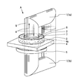
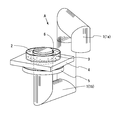
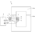
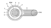
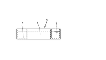
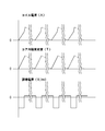
- FIG. 1 is a perspective view of a first embodiment of a culture solution container used in the present invention. It is a front sectional view of FIG. It is a perspective view of 2nd Example of the culture solution container used for this invention. It is a front sectional view of FIG. FIG. 8 is a front sectional view of another embodiment of FIG. 7; (A) (b) It is a perspective view of the magnetic core of this invention. It is a perspective view of 3rd Example of the culture solution container used for this invention. It is a time chart graph which shows a relation of coil current, magnetic flux density in a core, and induction magnetic field in the present invention.
- the present invention generates eddy current U (and electric field) fluctuating in the culture fluid 2 without using the immersion electrode in the culture fluid which is essential in the conventional apparatus (in other words, the culture fluid 2 is changed by the fluctuating magnetic field)
- the present inventors conducted intensive studies.
- the magnetic core 1 is used to penetrate concentrated and rapidly changing magnetic flux into the through holes 6 of the ring-shaped culture solution container 3 to stimulate cells in the culture solution 2 sufficiently. It has become possible to induce eddy currents U and the like.
- the current density of the channel 7a is partially increased by making the current application cross-sectional area S1 of a part (current channel 7a) of the current channel in the culture solution 2 smaller than the current cross-sectional area S2 of the other current channels. It has become possible to perform stronger electrical stimulation on the cells in the part 7a.
- the present apparatus A is roughly composed of a culture solution container 3, a magnetic core 1, an excitation coil 5, and a coil power supply 8 for supplying a fluctuating current (pulse current or alternating current) to the excitation coil 5. Be done.
- the culture solution container 3 is a ring-shaped container having a ring shape or a rectangular shape in a plan view, and a polygonal through hole 6 having a circular shape or a square shape is formed in the center thereof.
- a ring-shaped recess 7 having a ring-like or square-like shape in plan view and open in top view is recessed to form a structure capable of storing the culture fluid 2 therein.
- the culture solution container 3 shown in FIG. 6 is a longitudinal cross section passing through the center of the through hole 6 in FIG. 6 and has a current-carrying cross-sectional area S2 (i.e., a longitudinal cross-sectional cross-sectional area of the culture fluid 2) It is equally formed over the entire circumference.
- the culture solution container 3 shown in FIGS. 7 to 9 is a modification of the culture solution container 3 shown in FIG.
- An energization cross-sectional area S1 which is a longitudinal cross-section of a portion of the bottleneck 7a passing through the center is formed smaller than the energization cross-sectional area S2 of the other portion of the ring-shaped recess 7.
- the bottleneck 7a is an example in which the bottom of the bottleneck 7a is formed higher than the bottom of the other portion, and in FIG. 9, the groove width is formed narrower than the other portion in plan view. Is an example.
- an eddy current U is generated with the ring-shaped recess 7 as a current passage.
- the through hole 6 is provided inside the ring-shaped recess 7 of the culture solution container 3, and the magnetic core 1 made of a ferromagnetic material penetrates the through hole 6.
- a conductor is wound around the magnetic core 1 as an exciting coil 5, and a coil power supply 8 for supplying a fluctuating current is connected to the exciting coil 5 by a cable (not shown).
- the magnetic core 1 is formed of a laminated silicon steel plate or other material mentioned above, and when it is formed of an electromagnetic steel plate 9 (or other laminated material mentioned above) using a silicon steel plate, a direction perpendicular to the magnetic flux direction g of the magnetic core 1 (In other words, the lamination surface is laminated in a direction parallel to the magnetic flux direction g).
- the shape of the magnetic core 1 is sufficient as long as it can be inserted into the through hole 6 of the culture solution container 3.
- the shape is, for example, a rod shape, a U shape (or a horseshoe shape), a L shape forming a closed magnetic path (FIGS. 10) and so on. Since it is necessary to arrange the L-shaped magnetic core 1 so as to penetrate through the through hole 6 as described above, the magnetic core 1 is divided into upper and lower two, and is divided into a U-shaped upper core 1a and a lower core 1b.
- the cross-sectional shape of the magnetic core 1 may be circular as shown in FIGS. 1 and 2 or rectangular as shown in FIG.
- a magnetic core 1 of circular cross section is formed by stacking electromagnetic steel sheets 9 whose width is gradually reduced on both sides of a wide electromagnetic steel sheet 9 (or other laminated material described above), and the cross section is circular.
- 1 is a U-shaped or reverse U-shaped electromagnetic steel plate 9 stacked in a rectangular cross-section (Fig. 10 (a)), or multiple layers of electromagnetic steel plate band wound around a rectangular column and cut at the center (FIG. 10 (b)).
- an exciting current that is, a fluctuating current including a pulse exciting current or an AC exciting current
- an exciting current that is, a fluctuating current including a pulse exciting current or an AC exciting current
- the magnetic core 1 is ferromagnetic, its magnetic flux density is considerably high. For example, it is possible to generate a magnetic flux density of up to about 2.0 T (Tesla) by using a silicon steel sheet in the magnetic core 1 (FIG. 1) of the closed magnetic path and about 1.5 T by using an iron-based amorphous material. It is.
- the magnetic flux in the magnetic core fluctuates sharply in synchronization with the abrupt change of the excitation current. Since this magnetic core 1 is disposed to penetrate through the through hole 6 of the culture solution container 3, the high-density fluctuating magnetic flux penetrates the ring-shaped recess 7 of the culture solution container 3. As a result, an electric field and an eddy current U that try to cancel the fluctuating magnetic flux are generated in the culture solution 2 by electromagnetic induction, and cells in the culture solution 2 are stimulated.
- FIG. 1 An example of the current waveform of the exciting coil 5 when generating an induced electric field pulse, the magnetic flux waveform in the core, and the induced electric field induced in the culture solution 2 are shown in FIG. Since the magnitude of the induction field is proportional to the rate of change of the magnetic flux, in order to maintain a constant induction field, it is desirable to keep the flux in the magnetic core 1 constant. In order to give a constant change, it is necessary to make the current change larger as the magnetic flux density in the magnetic core 1 saturates.
- the circular container 3 shown in FIG. 5 is characterized in that a substantially uniform electric field can be generated over the entire circumference.
- the rectangular container 3 shown in FIG. 11 is characterized in that the electric field and the eddy current density generated at the four corners and the four sides are different.
- the culture solution container 3 needs to be nonmagnetic and non-electrically conductive like glass, in order to prevent the eddy current U from flowing into the culture solution container 3 at the time of electrical stimulation.
- the magnetic core 1 shown in FIG. 1 has a round cross section, and is suitable for the culture solution container 3 of the type shown in FIG.
- the magnetic core 1 shown in FIG. 10 is a magnetic core having a rectangular cross section, and is suitable for the culture solution container 3 of the type shown in FIG.
- the magnetic core 1 can be manufactured with a small eddy current loss by laminating the thin magnetic material insulated in any way in the direction orthogonal to the magnetic flux in the core.
- a material of the magnetic core 1 it is suitable to use a silicon steel plate having a large saturation magnetization.
- the shape of the magnetic core 1 is a closed magnetic path with a closed loop, the demagnetizing field in the magnetic core 1 is reduced, and the necessary magnetic flux is required to be generated in the magnetic core 1.
- a sufficiently large current flows even if the closed magnetic circuit is not used, useful electrical stimulation can be obtained for the cells.
- even in the open magnetic circuit it is possible to reduce the demagnetizing field by making the magnetic path length significantly larger than the cross sectional area (for example, a long rod-like core).
- the magnetic core 1 be provided with a stage 4 on which the culture solution container 3 is placed.
- Stage 4 also needs to be made of a nonmagnetic, non-electrically conductive material, as in culture medium container 3.
- a through hole 4 a is formed at a position matching the through hole 6.
- the magnetic core 1 When the magnetic core 1 is manufactured with a closed magnetic circuit, in order to set the culture solution container 3 on the stage 4, as described above, the magnetic core 1 needs to be divided in the middle (FIG. 1) , Figure 10).
- the upper core 1a of the divided magnetic core 1 is rotated and opened, and a portion of the lower core 1b projecting from the stage 4 is inserted into the through hole 6 of the culture solution container 3 and set again.
- the next electric stimulation can be performed only by replacing the culture solution container 3 without performing the sterilization operation as in the conventional immersion electrode. The ability to do this is a major advantage of the device.
- the exciting coil 5 is generally manufactured by winding a copper wire several times to several tens of times. When the number of turns is large, the inductance is high, and the output voltage required for the coil power supply 8 is high. Conversely, if the number of turns is small, a high output current is required of the coil power supply 8. As the coil power supply 8, it is preferable to use a large capacity high speed bipolar power supply or a pulse power supply specialized for pulse generation. In addition, as coil power supply 8, use of an alternating current power supply is also possible.
- the exciting coil 5 is preferably wound around the magnetic core 1 near the culture solution container 3.
- the culture solution container 3 As a modified example of the culture solution container 3, as described above, the culture in a shape in which a part of the ring-shaped recess 7 is used as the weir 7a in FIG. 7 to FIG. The liquid container 3 is shown.
- FIG. 8 shows a culture solution container of a type in which the cross-sectional area S1 is narrower than the cross-sectional area S2 of the other parts by making a part (the bottleneck 7a part) of the depth of the ring-shaped recess 7 shallower.
- the depth of a portion of the ring-shaped recess may be shallow and the width may be narrowed.
- Example 1 A silicon steel plate of width 90 mm and thickness 0.27 mm is wound around a core of 100 mm ⁇ 80 mm about 230 times to create a wound core with a magnetic path cross sectional area of 90 mm ⁇ 65 mm and a magnetic path length of 560 mm. It was divided into magnetic cores. Further, a culture solution container having a ring-shaped recess having a width of 16 mm and a depth of 18 mm and a ring length of 400 mm was manufactured of glass.
- the thickness of the glass is 2 mm
- the size of the container is 108 mm wide ⁇ 134 mm deep ⁇ 20 mm high
- a 68 mm ⁇ 94 mm through hole is provided in the center of the ring-shaped recess.
- a 1 ⁇ 11 mm rectangular wire was wound around the magnetic core four times, and this was used as an excitation coil.
- a coil power supply a pulse power supply was used, and an exciting coil and a coil power supply were connected by a cable of 8 mmsq.
- a glass epoxy board of the core was adhered to make a stage.
- the culture solution container was placed on the stage so that the manufactured magnetic core penetrated the through hole. Thereafter, 0.9% saline was poured into the culture solution container to a depth of 15 mm. As a result, the same configuration as that of FIG. 1 was completed.
- a three-dimensional cultured muscle with a length of about 10 mm was introduced into the culture solution.
- This three-dimensional cultured muscle is a collection of muscle cells, and is known to contract by applying a voltage of 40 V and a pulse width of 1 ms at an electrode of 50 mm intervals.
- a pulse voltage of 600 V was generated in the same manner as described above, a pulse current of about 1100 A flowed through the exciting coil.
- the pulse width of the pulse current was about 100 ⁇ s. Under this condition, contraction of three-dimensional cultured muscle could not be observed.
- the device according to the present invention can be a very important device in studies of various cell control and production of products using cells, including studies of pluripotent stem cells such as iPS cells and ES cells.
- A electric stimulation device, S1 ⁇ S2: conduction cross section, U: eddy current, g: magnetic flux direction, 1: magnetic core, 1a: upper core, 1b: lower core, 2: culture fluid, 3: culture fluid container, 4: Stage, 4a: Through hole, 5: Excitation coil, 6: Through hole, 7: Ring recess, 7a: Pinhole, 8: Power supply for coil, 9: Electrical steel sheet
Landscapes
- Health & Medical Sciences (AREA)
- Engineering & Computer Science (AREA)
- Life Sciences & Earth Sciences (AREA)
- Bioinformatics & Cheminformatics (AREA)
- Organic Chemistry (AREA)
- Chemical & Material Sciences (AREA)
- Zoology (AREA)
- Wood Science & Technology (AREA)
- Genetics & Genomics (AREA)
- Biotechnology (AREA)
- Biomedical Technology (AREA)
- General Health & Medical Sciences (AREA)
- Microbiology (AREA)
- Sustainable Development (AREA)
- Biochemistry (AREA)
- General Engineering & Computer Science (AREA)
- Cell Biology (AREA)
- Clinical Laboratory Science (AREA)
- Physics & Mathematics (AREA)
- Electromagnetism (AREA)
- Public Health (AREA)
- Nuclear Medicine, Radiotherapy & Molecular Imaging (AREA)
- Radiology & Medical Imaging (AREA)
- Animal Behavior & Ethology (AREA)
- Veterinary Medicine (AREA)
- Immunology (AREA)
- Neurology (AREA)
- Apparatus Associated With Microorganisms And Enzymes (AREA)
- Micro-Organisms Or Cultivation Processes Thereof (AREA)
Abstract
Priority Applications (5)
| Application Number | Priority Date | Filing Date | Title |
|---|---|---|---|
| JP2017546261A JP6258567B1 (ja) | 2016-05-26 | 2017-05-19 | 培養液中の細胞の非接触電気刺激装置と非接触電気刺激方法 |
| EP17802703.3A EP3467094B1 (fr) | 2016-05-26 | 2017-05-19 | Appareil et procédé de stimulation électrique sans contact des cellules dans un milieu de culture liquide |
| CN201780031392.XA CN109153957B (zh) | 2016-05-26 | 2017-05-19 | 培养液中的细胞的非接触电刺激装置和非接触电刺激方法 |
| US16/302,350 US11001798B2 (en) | 2016-05-26 | 2017-05-19 | Apparatus and method for non-contact electrical stimulation of cells in liquid culture medium |
| KR1020187033819A KR102156527B1 (ko) | 2016-05-26 | 2017-05-19 | 배양액 중의 세포의 비접촉 전기 자극 장치와 비접촉 전기 자극 방법 |
Applications Claiming Priority (2)
| Application Number | Priority Date | Filing Date | Title |
|---|---|---|---|
| JP2016-105075 | 2016-05-26 | ||
| JP2016105075 | 2016-05-26 |
Publications (1)
| Publication Number | Publication Date |
|---|---|
| WO2017204111A1 true WO2017204111A1 (fr) | 2017-11-30 |
Family
ID=60411968
Family Applications (1)
| Application Number | Title | Priority Date | Filing Date |
|---|---|---|---|
| PCT/JP2017/018850 Ceased WO2017204111A1 (fr) | 2016-05-26 | 2017-05-19 | Appareil et procédé de stimulation électrique sans contact des cellules dans un milieu de culture liquide |
Country Status (6)
| Country | Link |
|---|---|
| US (1) | US11001798B2 (fr) |
| EP (1) | EP3467094B1 (fr) |
| JP (1) | JP6258567B1 (fr) |
| KR (1) | KR102156527B1 (fr) |
| CN (1) | CN109153957B (fr) |
| WO (1) | WO2017204111A1 (fr) |
Cited By (3)
| Publication number | Priority date | Publication date | Assignee | Title |
|---|---|---|---|---|
| CN111013018A (zh) * | 2018-10-09 | 2020-04-17 | 胜美达集团株式会社 | 生物体刺激用磁场产生装置 |
| JP2020162594A (ja) * | 2019-03-28 | 2020-10-08 | 財團法人國家衛生研究院National Health Research Institutes | 細胞培養皿及びその電磁刺激培養システム |
| CN111996120A (zh) * | 2020-09-25 | 2020-11-27 | 南通纺织丝绸产业技术研究院 | 一种带有微电流刺激功能的细胞培养装置 |
Families Citing this family (7)
| Publication number | Priority date | Publication date | Assignee | Title |
|---|---|---|---|---|
| US9809810B2 (en) * | 2013-02-05 | 2017-11-07 | Ohio State Innovation Foundation | Galvanotaxis assay for quantitative assessment of the metastatic potential of cancer cells |
| US9885031B2 (en) | 2013-02-05 | 2018-02-06 | Ohio State Innovation Foundation | Galvanotaxis assay for quantitative assessment of the metastatic potential of cancer cells |
| KR102348640B1 (ko) * | 2019-08-07 | 2022-01-07 | 엘지전자 주식회사 | 전기천공 장치 |
| JP7505720B2 (ja) * | 2020-04-16 | 2024-06-25 | ディーエイチエフ アメリカ,エルエルシー | 細胞シート用の磁場発生器 |
| CN112501019B (zh) * | 2020-12-03 | 2023-10-31 | 广州迈普再生医学科技股份有限公司 | 一种多功能生物反应器 |
| CN113005037B (zh) * | 2021-04-12 | 2024-05-28 | 深圳市第二人民医院(深圳市转化医学研究院) | 一种用于细胞培养的电极绝缘垫及其非接触电场装置和方法 |
| CN118389263B (zh) * | 2024-05-29 | 2024-11-19 | 上海昱极细胞生物技术有限公司 | 一种具有环境模拟功能的nk细胞活性检测装置 |
Citations (5)
| Publication number | Priority date | Publication date | Assignee | Title |
|---|---|---|---|---|
| JP2003274940A (ja) * | 2002-03-26 | 2003-09-30 | Kumamoto Technology & Industry Foundation | 培養細胞又は組織の育成法 |
| JP2004290180A (ja) * | 2003-03-10 | 2004-10-21 | Japan Science & Technology Agency | 磁場刺激装置及びその磁場刺激装置を用いた生体細胞若しくは生体組織の成長促進又は抑制方法 |
| JP2004305120A (ja) * | 2003-04-08 | 2004-11-04 | Kumamoto Technology & Industry Foundation | 臓器、または組織、あるいはこれらを構成する細胞の機能馴化方法 |
| JP2005350396A (ja) * | 2004-06-10 | 2005-12-22 | Japan Science & Technology Agency | 特定細胞の処理方法及び特定細胞の処理装置 |
| JP2014161323A (ja) * | 2013-02-27 | 2014-09-08 | Tohoku Univ | 細胞培養法と該方法に使用する磁気刺激コイル並びに電源ケーブル |
Family Cites Families (16)
| Publication number | Priority date | Publication date | Assignee | Title |
|---|---|---|---|---|
| EP1130397B1 (fr) * | 1993-02-01 | 2006-10-11 | Thermo Electron Oy | Equipment pour la détermination d'un analyte dans un échantillon |
| JP2002001092A (ja) * | 2000-06-22 | 2002-01-08 | Shimadzu Corp | 排液装置 |
| JP3600874B2 (ja) | 2001-11-13 | 2004-12-15 | 独立行政法人理化学研究所 | 細胞刺激装置及び細胞刺激方法 |
| JP2004129603A (ja) | 2002-10-11 | 2004-04-30 | National Cardiovascular Center | 細胞分化誘導法 |
| JP2005027501A (ja) | 2003-07-07 | 2005-02-03 | Rui Yuge | 自動収縮筋細胞の製造方法 |
| FI20051248A7 (fi) * | 2005-12-02 | 2007-06-03 | Biocontrol Systems Oy | Biologisten komponenttien rikastusyksikkö ja rikastusmenetelmä |
| DE102006015550B4 (de) * | 2006-03-31 | 2008-09-25 | Technische Universität Dresden | Verfahren und Vorrichtung zur Einkopplung eines elektrischen Feldes in ein physiologisches und elektrisch leitfähiges Medium |
| EP2081645B8 (fr) | 2006-11-08 | 2013-07-10 | P· MIND Co., Ltd | Appareil accelerant la production de facteur neurotrophique |
| DE102008036798A1 (de) | 2008-08-07 | 2010-02-18 | Tmt Tapping-Measuring-Technology Gmbh | Verfahren und Vorrichtung zur Regelung der Strömungsgeschwindigkeit und zum Abbremsen von Schmelzeströmen durch Magnetfelder, insbesondere beim Abstich von metallurgischen Behältern wie Hochöfen und Schmelzöfen |
| KR101443727B1 (ko) * | 2010-04-30 | 2014-09-26 | (주)바이오니아 | 자기장 인가부를 구비한 생물학적 시료 자동정제장치, 생물학적 시료로부터 타겟물질을 추출하는 방법 그리고 단백질 발현 및 정제 방법 |
| US20120252088A1 (en) * | 2011-03-29 | 2012-10-04 | Jie Zhang | Floating magnet probe for cell isolation |
| CN102512756B (zh) * | 2011-12-06 | 2014-10-22 | 何宗彦 | 一种用于处理物体中生物细胞的方法及设备 |
| EP2861712A1 (fr) * | 2012-06-13 | 2015-04-22 | Universitat Politècnica De Catalunya | Procédés et dispositifs de stimulation mécanique et électrique de cultures de cellules souches tridimensionnelles ou en couche monocellulaire pour des applications de génie tissulaire |
| GB2539174B (en) * | 2014-04-04 | 2020-10-28 | Synthecon Inc | Bioreactor system for stem cell expansion |
| CN105268388B (zh) * | 2015-09-14 | 2017-08-25 | 江南大学 | 一种循环式磁电感应反应系统及其应用 |
| US9656267B2 (en) * | 2015-09-17 | 2017-05-23 | Nvigen, Inc. | Magnetic rack |
-
2017
- 2017-05-19 WO PCT/JP2017/018850 patent/WO2017204111A1/fr not_active Ceased
- 2017-05-19 CN CN201780031392.XA patent/CN109153957B/zh not_active Expired - Fee Related
- 2017-05-19 EP EP17802703.3A patent/EP3467094B1/fr active Active
- 2017-05-19 US US16/302,350 patent/US11001798B2/en not_active Expired - Fee Related
- 2017-05-19 KR KR1020187033819A patent/KR102156527B1/ko active Active
- 2017-05-19 JP JP2017546261A patent/JP6258567B1/ja active Active
Patent Citations (5)
| Publication number | Priority date | Publication date | Assignee | Title |
|---|---|---|---|---|
| JP2003274940A (ja) * | 2002-03-26 | 2003-09-30 | Kumamoto Technology & Industry Foundation | 培養細胞又は組織の育成法 |
| JP2004290180A (ja) * | 2003-03-10 | 2004-10-21 | Japan Science & Technology Agency | 磁場刺激装置及びその磁場刺激装置を用いた生体細胞若しくは生体組織の成長促進又は抑制方法 |
| JP2004305120A (ja) * | 2003-04-08 | 2004-11-04 | Kumamoto Technology & Industry Foundation | 臓器、または組織、あるいはこれらを構成する細胞の機能馴化方法 |
| JP2005350396A (ja) * | 2004-06-10 | 2005-12-22 | Japan Science & Technology Agency | 特定細胞の処理方法及び特定細胞の処理装置 |
| JP2014161323A (ja) * | 2013-02-27 | 2014-09-08 | Tohoku Univ | 細胞培養法と該方法に使用する磁気刺激コイル並びに電源ケーブル |
Cited By (5)
| Publication number | Priority date | Publication date | Assignee | Title |
|---|---|---|---|---|
| CN111013018A (zh) * | 2018-10-09 | 2020-04-17 | 胜美达集团株式会社 | 生物体刺激用磁场产生装置 |
| CN111013018B (zh) * | 2018-10-09 | 2024-03-29 | 胜美达集团株式会社 | 生物体刺激用磁场产生装置 |
| JP2020162594A (ja) * | 2019-03-28 | 2020-10-08 | 財團法人國家衛生研究院National Health Research Institutes | 細胞培養皿及びその電磁刺激培養システム |
| CN111996120A (zh) * | 2020-09-25 | 2020-11-27 | 南通纺织丝绸产业技术研究院 | 一种带有微电流刺激功能的细胞培养装置 |
| JP2022544729A (ja) * | 2020-09-25 | 2022-10-21 | 南通紡織絲綢産業技術研究院 | 微電流刺激機能付きの細胞培養装置 |
Also Published As
| Publication number | Publication date |
|---|---|
| EP3467094A1 (fr) | 2019-04-10 |
| EP3467094B1 (fr) | 2020-01-01 |
| EP3467094A4 (fr) | 2019-05-01 |
| KR102156527B1 (ko) | 2020-09-16 |
| JPWO2017204111A1 (ja) | 2018-06-14 |
| KR20180135485A (ko) | 2018-12-20 |
| US20190161722A1 (en) | 2019-05-30 |
| US11001798B2 (en) | 2021-05-11 |
| CN109153957A (zh) | 2019-01-04 |
| CN109153957B (zh) | 2021-07-06 |
| JP6258567B1 (ja) | 2018-01-10 |
Similar Documents
| Publication | Publication Date | Title |
|---|---|---|
| JP6258567B1 (ja) | 培養液中の細胞の非接触電気刺激装置と非接触電気刺激方法 | |
| Novickij et al. | Compact microsecond pulsed magnetic field generator for application in bioelectronics | |
| Novickij et al. | Magneto-permeabilization of viable cell membrane using high pulsed magnetic field | |
| US20150080637A1 (en) | Microscopic magnetic coils for neural stimulation | |
| US10844364B2 (en) | Non-contact system for accelerating wound healing using an electromagnetic coil to induce an electric field transverse to an axis of the wound | |
| Novickij et al. | Reversible permeabilization of cancer cells by high sub-microsecond magnetic field | |
| Sun et al. | Electrode microchamber for noninvasive perturbation of mammalian cells with nanosecond pulsed electric fields | |
| Yapici et al. | Alternating magnetic field plate for enhanced magnetofection of iron oxide nanoparticle conjugated nucleic acids | |
| US9247630B2 (en) | Surface-micromachined micro-magnetic undulator | |
| KR102025990B1 (ko) | 균일 자기장 세포 자극 시스템 | |
| Novickij et al. | High-pulsed electromagnetic field generator for contactless permeabilization of cells in vitro | |
| CN214781905U (zh) | 一种用于细胞培养的非接触电场装置 | |
| JP6019404B2 (ja) | 細胞培養法と該方法に使用する磁気刺激コイル並びに電源ケーブル | |
| Misakian et al. | Optimal experimental design for in vitro studies with ELF magnetic fields | |
| ATE336281T1 (de) | Eine vorrichtung und eine methode zur anregung/modulation biochemischer prozesser durch pulsierende elektromagnetische felder von mehrfachspulen | |
| JP6626780B2 (ja) | 培養液中の細胞の電気刺激装置 | |
| JPH0270099A (ja) | 電気めっき方法及び装置 | |
| CN112334186A (zh) | 粒子束照射系统、粒子束照射方法、照射计划程序、照射计划装置、电磁场生成装置以及照射装置 | |
| US12139699B2 (en) | Magnetic-field generator for a cell sheet | |
| Glinka et al. | Action of the static magnetic fields on the antioxidant activity in the fibroblasts’ culture | |
| CN113122448A (zh) | 一种用于细胞培养的非接触电场装置及其细胞培养方法 | |
| US20200360539A1 (en) | Alternating current magnet system for magnet-assisted transfection | |
| Bonmassar | Theoretical Distance Constraints in Multi-Site Short-Pulsed Microscopic Magnetic Stimulation: How Close is Too Close? | |
| Bajtoš et al. | INVESTIGATION OF EXTREMELY LOW-FREQUENCY MAGNETIC FIELD BIOEFFECT AT CELLULAR LEVEL CONCERNING ICNIRP GUIDELINES AND EXPOSURE LIMITS | |
| CN106867901A (zh) | 一种以磁性液体为媒介的细胞铺板装置 |
Legal Events
| Date | Code | Title | Description |
|---|---|---|---|
| ENP | Entry into the national phase |
Ref document number: 2017546261 Country of ref document: JP Kind code of ref document: A |
|
| ENP | Entry into the national phase |
Ref document number: 20187033819 Country of ref document: KR Kind code of ref document: A |
|
| NENP | Non-entry into the national phase |
Ref country code: DE |
|
| 121 | Ep: the epo has been informed by wipo that ep was designated in this application |
Ref document number: 17802703 Country of ref document: EP Kind code of ref document: A1 |
|
| ENP | Entry into the national phase |
Ref document number: 2017802703 Country of ref document: EP Effective date: 20190102 |