WO2017204183A1 - Dispositif d'embrayage - Google Patents
Dispositif d'embrayage Download PDFInfo
- Publication number
- WO2017204183A1 WO2017204183A1 PCT/JP2017/019108 JP2017019108W WO2017204183A1 WO 2017204183 A1 WO2017204183 A1 WO 2017204183A1 JP 2017019108 W JP2017019108 W JP 2017019108W WO 2017204183 A1 WO2017204183 A1 WO 2017204183A1
- Authority
- WO
- WIPO (PCT)
- Prior art keywords
- bush
- bush portion
- spring seat
- shaft body
- rotating body
- Prior art date
- Legal status (The legal status is an assumption and is not a legal conclusion. Google has not performed a legal analysis and makes no representation as to the accuracy of the status listed.)
- Ceased
Links
Images


Classifications
-
- F—MECHANICAL ENGINEERING; LIGHTING; HEATING; WEAPONS; BLASTING
- F16—ENGINEERING ELEMENTS AND UNITS; GENERAL MEASURES FOR PRODUCING AND MAINTAINING EFFECTIVE FUNCTIONING OF MACHINES OR INSTALLATIONS; THERMAL INSULATION IN GENERAL
- F16C—SHAFTS; FLEXIBLE SHAFTS; ELEMENTS OR CRANKSHAFT MECHANISMS; ROTARY BODIES OTHER THAN GEARING ELEMENTS; BEARINGS
- F16C35/00—Rigid support of bearing units; Housings, e.g. caps, covers
- F16C35/02—Rigid support of bearing units; Housings, e.g. caps, covers in the case of sliding-contact bearings
-
- F—MECHANICAL ENGINEERING; LIGHTING; HEATING; WEAPONS; BLASTING
- F16—ENGINEERING ELEMENTS AND UNITS; GENERAL MEASURES FOR PRODUCING AND MAINTAINING EFFECTIVE FUNCTIONING OF MACHINES OR INSTALLATIONS; THERMAL INSULATION IN GENERAL
- F16D—COUPLINGS FOR TRANSMITTING ROTATION; CLUTCHES; BRAKES
- F16D41/00—Freewheels or freewheel clutches
- F16D41/06—Freewheels or freewheel clutches with intermediate wedging coupling members between an inner and an outer surface
- F16D41/064—Freewheels or freewheel clutches with intermediate wedging coupling members between an inner and an outer surface the intermediate members wedging by rolling and having a circular cross-section, e.g. balls
- F16D41/066—Freewheels or freewheel clutches with intermediate wedging coupling members between an inner and an outer surface the intermediate members wedging by rolling and having a circular cross-section, e.g. balls all members having the same size and only one of the two surfaces being cylindrical
-
- F—MECHANICAL ENGINEERING; LIGHTING; HEATING; WEAPONS; BLASTING
- F16—ENGINEERING ELEMENTS AND UNITS; GENERAL MEASURES FOR PRODUCING AND MAINTAINING EFFECTIVE FUNCTIONING OF MACHINES OR INSTALLATIONS; THERMAL INSULATION IN GENERAL
- F16H—GEARING
- F16H55/00—Elements with teeth or friction surfaces for conveying motion; Worms, pulleys or sheaves for gearing mechanisms
- F16H55/32—Friction members
- F16H55/36—Pulleys
-
- F—MECHANICAL ENGINEERING; LIGHTING; HEATING; WEAPONS; BLASTING
- F16—ENGINEERING ELEMENTS AND UNITS; GENERAL MEASURES FOR PRODUCING AND MAINTAINING EFFECTIVE FUNCTIONING OF MACHINES OR INSTALLATIONS; THERMAL INSULATION IN GENERAL
- F16C—SHAFTS; FLEXIBLE SHAFTS; ELEMENTS OR CRANKSHAFT MECHANISMS; ROTARY BODIES OTHER THAN GEARING ELEMENTS; BEARINGS
- F16C17/00—Sliding-contact bearings for exclusively rotary movement
- F16C17/02—Sliding-contact bearings for exclusively rotary movement for radial load only
Definitions
- the present invention relates to a clutch device.
- an alternator used as an auxiliary machine for an automobile engine is configured to be driven by a rotational force transmitted from the crankshaft of the engine. That is, a pulley is attached to the rotating shaft of the alternator, a belt is stretched between the pulley and the pulley on the crankshaft side, and the rotational force of the crankshaft is transmitted to the alternator through the belt. It has become.
- crankshaft rotational force is based on the explosive force of the engine cylinder, so the crankshaft rotational speed varies.
- the alternator side cannot follow the sudden fluctuation of the rotational speed of the crankshaft, and a rotational speed difference is temporarily generated between the crankshaft and the alternator.
- a difference in rotational speed causes the belt to slip or an excessive load applied to the belt, causing abnormal noise and shortening the service life. Therefore, the pulley for the alternator is provided with a clutch portion for transmitting and blocking rotational force and a spring mechanism for absorbing a rotational speed difference (see, for example, Patent Document 1).
- the clutch device 90 includes a shaft body 91 attached to a rotating shaft (not shown) of an alternator, a cylindrical outer member 99 provided on the radially outer side of the shaft body 91 and having a pulley portion 98, and a clutch portion 97. And a coil spring 96 for absorbing rotational fluctuation between the shaft body 91 and the outer member 99, and bearing portions 95 and 94 that support the shaft body 91 and the outer member 99 so as to be relatively rotatable. ing.
- the bearing portion 95 on one axial side is a rolling bearing, and includes an outer ring 95a fitted to the outer member 99, an inner ring 95b fitted to the shaft body 91, and a plurality of balls 95c. And a cage 95d for holding these balls 95c.
- the bearing portion 94 on the other side in the axial direction is a sliding bearing, and is provided between the spring seat 92 integral with the shaft body 91 and the outer member 99.
- the bearing portion 94 is made of, for example, a resin bush 93, and the outer peripheral surface of the bush 93 is in sliding contact with a part of the inner peripheral surface of the outer member 99.
- the coil spring 96 included in the clutch device 90 can absorb the rotational speed difference (rotational fluctuation) between the shaft body 91 and the outer member 99. If the function is insufficient, the belt slips at the pulley portion 98, and a large load acts on each portion of the belt and the clutch device 90. Moreover, if such a phenomenon occurs frequently, each part of the clutch device 90 may be worn and damaged, and the product life may be reduced.
- the life of the clutch device can be extended.
- the clutch device includes a shaft body, an outer rotating body provided on a radially outer side of the shaft body, a free state in which the shaft body and the outer rotating body can be relatively rotated, and the relative rotation is disabled.
- a clutch portion that selectively switches a locked state, a coil spring that absorbs rotational fluctuations between the shaft body and the outer rotating body in the locked state, and the shaft body and the outer side in the free state.
- a bearing that supports the rotating body as being relatively rotatable, The clutch portion is provided on the radially outer side of the shaft body, and the coil spring for absorbing the rotation fluctuation is provided on the radially outer side of the clutch portion.
- the diameter of the coil spring is increased, and the spring constant of the coil spring can be increased. For this reason, the rotational fluctuation absorption characteristic of the clutch device becomes high, and even if, for example, a sudden rotational fluctuation occurs between the shaft body and the outer rotating body, it can be absorbed, and each part of the clutch device is greatly affected. It is possible to prevent the load from acting. As a result, the life of the clutch device is extended.
- the clutch device includes a rolling bearing and a sliding bearing as the bearing,
- the sliding bearing holds a grease between a first bush portion provided on one side in the axial direction between a part of the shaft body and a part of the outer rotating body, and the first bush part. And a second bush portion provided on the other side in the axial direction so as to form a space for use.
- a space is formed between the first bush portion and the second bush portion of the slide bearing between a part of the shaft body and a part of the outer rotating body, and grease is stored in this space.
- the outer rotating body includes a first spring seat provided on the radially outer side of the shaft body via the clutch portion, and a cylindrical outer member provided on the radially outer side of the first spring seat.
- a second spring seat that is axially separated from the first spring seat and is rotatable integrally with the outer member,
- the coil spring has one end attached to the first spring seat and the other end attached to the second spring seat, and the clutch portion performs relative rotation between the shaft body and the first spring seat.
- the first bush portion and the second bush portion have a function of selectively switching between a free state to be enabled and a locked state to disable the relative rotation, and the first bush portion and the second bush portion have an inner peripheral surface of the second spring seat and the It is good also as a structure provided between the outer peripheral surfaces of a shaft.
- the clutch device includes the shaft body, the first spring seat provided on the radially outer side of the shaft body, and the cylindrical outer member provided on the radially outer side of the first spring seat. And an outer rotating body having a second spring seat that is provided apart from the first spring seat in the axial direction and is rotatable integrally with the outer member, the shaft body, and the first A clutch portion that selectively switches between a free state that enables relative rotation with the spring seat and a locked state that disables the relative rotation, and one end portion attached to the first spring seat and the other end portion being the second A coil spring that is attached to a spring seat and absorbs rotational fluctuations between the first spring seat and the second spring seat that rotate integrally with the shaft body in the locked state; and in the free state,
- the shaft body and the outer member are supported to be relatively rotatable.
- a rolling bearing in the free state, a configuration including a sliding bearing which supports a relatively rotatable with said shaft member and the second spring seat.
- the sliding bearing includes a first bush portion provided on one side in the axial direction between the outer peripheral surface of the shaft body and the inner peripheral surface of the second spring seat, and the first bush portion.
- a grease holding space is formed between the second bush portions provided on the other side in the axial direction.
- the first bush portion and the second bush portion are fitted to the inner peripheral side of the second spring seat, and are between the outer peripheral surface of the first bush portion and the inner peripheral surface of the second spring seat. Is provided with an uneven portion that prevents the axial movement of the first bush portion relative to the second spring seat by fitting, and the outer peripheral surface of the second bush portion and the inner periphery of the second spring seat It is preferable that an uneven portion that prevents the movement of the second bush portion in the axial direction with respect to the second spring seat by fitting is provided between the surfaces. According to this configuration, the outer peripheral surfaces of the first bush portion and the second bush portion become the mating surfaces with the second spring seat, but these bush portions come out of the second spring seat in the axial direction by the uneven portion. Can be prevented.
- At least one bush portion of the first bush portion and the second bush portion is provided with a notch for widening the space formed between the other bush portion. Is preferred. According to this configuration, it is possible to increase the area where the grease can be stored, and to further ensure good lubricity over a long period of time with the grease.
- the slide bearing further includes a connecting bush portion interposed between the first bush portion and the second bush portion and integrating the first bush portion and the second bush portion.
- a connecting bush portion interposed between the first bush portion and the second bush portion and integrating the first bush portion and the second bush portion.
- the connecting bush portion may be a plurality of pillar portions that are provided at intervals in the circumferential direction and connect the first bush portion that is annular and the second bush portion that is annular. In this case, the space for retaining the grease is between the first bush portion and the second bush portion and between the column portions adjacent in the circumferential direction.
- the connecting bush portion is formed between an annular third bush portion provided between the annular first bush portion and the annular second bush portion, and the axially adjacent bush portion. It is good also as a structure which has a pillar part to connect.
- the space for holding the grease is between the first bush portion and the third bush portion, and the space for holding the grease is between the second bush portion and the third bush portion.
- One or a plurality of third bush portions may be provided. In the case of a plurality of third bush portions, the third bush portions are connected to each other by a column portion, and the third bush portions are also used for holding the grease. Space.
- the clutch device includes a shaft body, an outer rotating body provided on a radially outer side of the shaft body, a free state that enables relative rotation of the shaft body and the outer rotating body, and the relative rotation.
- a clutch portion that selectively switches a locked state that disables the shaft, a coil spring that absorbs rotational fluctuations between the shaft body and the outer rotating body in the locked state, and the shaft body in the free state
- a rolling bearing and a plain bearing that support the outer rotating body as being relatively rotatable
- the sliding bearing holds a grease between a first bush portion provided on one side in the axial direction between a part of the shaft body and a part of the outer rotating body, and the first bush part.
- a second bush portion provided on the other side in the axial direction so as to form a space for use.
- a space is formed between the first bush portion and the second bush portion of the sliding bearing between a part of the shaft body and a part of the outer rotating body, and grease is applied to this space.
- the shaft body and the outer rotating body are supported by a rolling bearing and a sliding bearing.
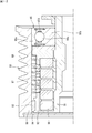
- FIG. 1 is a cross-sectional view showing an embodiment of the clutch device of the present invention.
- the clutch device 10 of this embodiment is attached to a rotating shaft of an alternator (not shown).
- the clutch device 10 includes a shaft body 11, an outer rotating body 20, a clutch portion 30, a coil spring 15, a rolling bearing 40, and a sliding bearing 50.
- the shaft body 11 is a cylindrical member, and is connected to the rotating shaft of the alternator on the inner peripheral side thereof.
- the shaft body 11 includes a first cylindrical portion 11a on one axial side (right side in FIG. 1), a second cylindrical portion 11b on the other axial side (left side in FIG. 1), and a third cylindrical portion 11c at the center in the axial direction. And have.
- a rolling bearing 40 is fitted and attached to the first cylindrical portion 11a.
- a sliding bearing 50 is fitted on the second cylinder portion 11b in a state of clearance fitting, and the sliding bearing 50 is in sliding contact with the outer peripheral surface 12 of the second cylinder portion 11b.
- the inner ring member 31 of the clutch part 30 is fitted and attached to the third cylinder part 11c, and these rotate integrally.
- the outer rotating body 20 includes an outer member 23, a first spring seat 21 and a second spring seat 22.
- the outer member 23 is a cylindrical member, and has a pulley portion 24 for hanging a belt (not shown) on one axial side of the outer periphery thereof.
- the first spring seat 21 is a cylindrical member, and is provided on the radially outer side of the shaft body 11 with the clutch portion 30 interposed therebetween.
- An outer member 23 is provided on the radially outer side of the first spring seat 21, and a gap is formed between the first spring seat 21 and the outer member 23.
- the inner peripheral surface 21a of the first spring seat 21 is formed of a cylindrical surface having the axis C of the clutch device 10 as a center line, and a cylindrical roller 33 of the clutch portion 30 described later is disposed on one axial side of the inner peripheral surface 21a. Rolling contact is made, and the other side in the axial direction of the inner peripheral surface 21a comes into contact with or leaves a needle roller 32 of the clutch portion 30 described later.
- the second spring seat 22 is a cylindrical member, fitted and attached to the inner peripheral side of the outer member 23, and the second spring seat 22 and the outer member 23 rotate integrally.
- the second spring seat 22 is provided away from the first spring seat 21 in the axial direction.
- the inner peripheral surface 22a of the second spring seat 22 is formed of a cylindrical surface having the axis C as the center line, and the sliding bearing 50 is attached to the inner peripheral surface 22a in an interference fit.
- the coil spring 15 is attached between the first spring seat 21 and the second spring seat 22.
- One end portion 16 of the coil spring 15 is fixed to the first spring seat 21, and the other end portion 17 is fixed to the second spring seat 22.
- the outer side member 23, the 2nd spring seat 22, the coil spring 15, and the 1st spring seat 21 can rotate integrally.
- the clutch portion 30 is in a locked state, and the shaft body 11, the inner ring member 31, and the first spring seat 21 can rotate together with the shaft body 11 and the outer member 23.
- this rotational fluctuation (rotational speed difference) can be absorbed by the coil spring 15.
- the clutch unit 30 includes an inner ring member 31 and a plurality of rollers (needle rollers) 32.
- the clutch unit 30 has a plurality of cylindrical rollers 33.
- the inner ring member 31 rotates integrally with the shaft body 11.
- the outer peripheral surface of the inner ring member 31 has a raceway surface 31a on one axial side and a cam surface 31b on the other axial side.
- the raceway surface 31a consists of a cylindrical surface with the axis C as the center line, and the plurality of cylindrical rollers 33 are in rolling contact.
- the cylindrical rollers 33 are held at intervals in the circumferential direction by an annular retainer (not shown), and support the inner ring member 31 and the first spring seat 21 so as to be concentric, and the first A radial load acting on the spring seat 21 can be received.
- the cam surface 31 b of the inner ring member 31 is provided with a plurality of concave portions 34 along the circumferential direction, and a wedge shape is formed between the concave portion 34 and the inner peripheral surface 21 a of the first spring seat 21.
- a space 35 is formed.
- One needle roller 32 is provided in each wedge-shaped space 35.
- a spring that biases the needle roller 32 in a direction in which the wedge-shaped space 35 is narrowed is provided.
- the outer member 23 having the pulley portion 24 tends to be constant or increased in speed, and the second spring seat 22, the coil spring 15, and the first spring seat 21 together with the outer member 23.
- the needle rollers 32 bite into the narrower region of the wedge-shaped space 35, and the recesses 34 and the inner peripheral surface 21a
- the clutch portion 30 is locked.
- the shaft body 11 and the inner ring member 31 and the first spring seat 21 are in a locked state in which relative rotation is disabled (that is, a locked state in which these are integrally rotatable).
- the outer member 23, the second spring seat 22, the coil spring 15, and the first spring seat 21 are configured to rotate integrally, so that the shaft body 11 and the outer member 23 rotate integrally in the locked state. It becomes possible.
- the clutch unit 30 can alternatively switch between the locked state and the free state according to the rotational speed of the outer member 23 with respect to the shaft body 11.
- the coil spring 15 has one end 16 attached to the first spring seat 21 and the other end 17 attached to the second spring seat 22 as described above. For this reason, when the clutch part 30 will be in a locked state, it has the function to absorb the rotation fluctuation
- the clutch portion 30 is provided on the radially outer side of the shaft body 11, and the coil spring 15 for absorbing rotational fluctuation is provided on the radially outer side of the clutch portion 30. It has been. Thereby, the diameter of the coil spring 15 is increased, and the spring constant of the coil spring 15 can be increased. For this reason, the rotational fluctuation absorption characteristic of the clutch device 10 becomes high, and even if, for example, a sudden rotational fluctuation occurs between the shaft body 11 and the outer rotary body 20, it can be absorbed. It is possible to prevent an impact load from acting on each part of the. As a result, the life of the clutch device 10 is extended.
- the wire constituting the coil spring 15 has a rectangular cross section that is longer in the axial direction than in the radial direction. Thereby, the clutch apparatus 10 is made compact in the radial direction.
- the rolling bearing 40 includes an outer ring 41 fitted on the outer member 23, an inner ring 42 fitted on the shaft body 11, a plurality of balls (rolling bodies) 43, and a cage 44 that holds these balls 43. And have.
- the outer ring 41 is fixed to the outer member 23.
- a washer 45 and a thrust bush 46 are interposed between the outer ring 41 and the first spring seat 21, and the outer ring 41 applies a thrust load of the first spring seat 21 via the washer 45 and the thrust bush 46. Can be supported.
- the thrust load of the first spring seat 21 depends on the elastic force of the coil spring 15.
- the rolling bearing 40 is attached between the shaft body 11 and the outer member 23, and can support the shaft body 11 and the outer member 23 so as to be relatively rotatable while the clutch portion 30 is in a free state. .
- FIG. 3 is a cross-sectional view showing the sliding bearing 50 and its surroundings.
- the slide bearing 50 includes a first bush portion 51 provided on one side in the axial direction and a second bush portion 52 provided on the other side in the axial direction.
- the first bush portion 51 and the second bush portion 52 are provided apart in the axial direction between the outer peripheral surface 12 of the shaft body 11 and the inner peripheral surface 22a of the second spring seat 22.
- a space 55 for retaining grease is formed between the bush portion 51 and the second bush portion 52.
- Each of the first bush portion 51 and the second bush portion 52 is an annular member, and is made of resin (for example, PTFE) in this embodiment.
- the first bush portion 51 is fitted to the second spring seat 22 with a fastening allowance
- the second bush portion 52 is fitted to the second spring seat 22 with a fastening allowance. That is, the bush portions 51 and 52 are in an interference fit state with the second spring seat 22.
- a minute gap is formed between the inner peripheral surface 51 a of the first bush portion 51 and the outer peripheral surface 12 of the shaft body 11. Further, a minute gap is formed between the inner peripheral surface 52 a of the second bush portion 52 and the outer peripheral surface 12 of the shaft body 11. That is, the bush portions 51 and 52 are in a clearance fit state with the shaft body 11, and are in sliding contact with the shaft body 11. As described above, the sliding bearing 50 is attached between the shaft body 11 and the second spring seat 22, and the shaft body 11, the second spring seat 22, and the outer member 23 are connected with the clutch portion 30 in a free state. It can be supported as being relatively rotatable.
- the clutch device 10 shown in FIG. 1 includes the shaft body 11 and the outer rotating body 20 provided on the radially outer side of the shaft body 11.
- the outer rotating body 20 includes a first spring seat 21 provided on the radially outer side of the shaft body 11 via a clutch portion 30, and a cylindrical outer side provided on the radially outer side of the first spring seat 21.
- the member 23 and the second spring seat 22 which is provided apart from the first spring seat 21 in the axial direction and can rotate integrally with the outer member 23 are included.
- the clutch device 10 includes a clutch portion 30, which is in a free state that allows relative rotation between the shaft body 11 and the outer rotating body 20 (first spring seat 21), and The lock state that disables relative rotation can be switched alternatively.
- the clutch device 10 further includes a coil spring 15 having one end portion 16 attached to the first spring seat 21 and the other end portion 17 attached to the second spring seat 22, and the clutch portion 30 is in the locked state.
- the coil spring 15 can absorb rotational fluctuations between the shaft body 11 and the outer rotating body 20.
- the clutch device 10 includes a rolling bearing 40 and a sliding bearing 50 that support the shaft body 11 and the outer rotating body 20 so that they can rotate relative to each other when the clutch unit 30 is in the free state.
- the sliding bearing 50 can support a radial load acting on the pulley portion 24 of the outer member 23.
- the bearing portion on the other side in the axial direction is the sliding bearing 50, the bearing portion can be disposed on the radially inner side of the second spring seat 22, and the clutch device 10 can be downsized.
- the cover 14 is attached to the edge part of the axial direction other side of the outer side member 23, ie, the edge part by the side of the 2nd spring seat 22, and the penetration
- the first bush portion 51 and the second bush portion 52 are the same, and both have a ring shape. As shown in FIG. 3, the first bush portion 51 and the second bush portion 52 are provided apart from each other in the axial direction, so that a space 55 for retaining grease is formed between them. It becomes an annular space (space continuous in the circumferential direction). Since the bush portions 51 and 52 are sandwiched between the second spring seat 22 and the shaft body 11, the grease holding space 55 is covered from both axial sides and from both radial sides. It becomes a closed annular space. When assembling these bush portions 51 and 52, the space 55 to be formed is filled with grease.
- the bush portions 51 and 52 are both annular, and the bush portions 51 and 52 are respectively attached to the inner peripheral surface 22 a by approaching the second spring seat 22 from the axial direction and press-fitting into the second spring seat 22. Thereby, the bush parts 51 and 52 will be in the state fitted with the allowance in the inner peripheral side of the 2nd spring seat 22.
- the bush portions 51 and 52 that are press-fitted and attached to the second spring seat 22 have a configuration for preventing the bush portions 51 and 52 from moving and dropping in the axial direction. That is, a convex portion 56 is provided on the outer peripheral surface 51 b of the first bush portion 51, and a concave portion 57 in which the convex portion 56 is fitted is formed on the inner peripheral surface 22 a of the second spring seat 22. Similarly, a convex portion 58 is provided on the outer peripheral surface 52 b of the second bush portion 52, and a concave portion 59 in which the convex portion 58 is fitted is formed on the inner peripheral surface 22 a of the second spring seat 22. Yes.
- the uneven part (56, 57) is provided between the outer peripheral surface 51b of the first bush part 51 and the inner peripheral surface 22a of the second spring seat 22, and the uneven part (56, 57) is provided.
- the uneven part (58, 59) is provided between the outer peripheral surface 52b of the second bush portion 52 and the inner peripheral surface 22a of the second spring seat 22, and the uneven portion (58, 59) is fitted. By doing so, the axial movement of the second bush portion 52 relative to the second spring seat 22 is prevented.
- the sliding bearing 50 of the clutch device 10 of the present embodiment is between the part of the shaft body 11 (second cylinder part 11b) and the part of the outer rotating body 20 (second spring seat 22).
- the first bush portion 51 and the second bush portion 52 are provided.
- the first bush portion 51 is provided on one side in the axial direction.
- the second bush portion 52 is provided on the other axial side with a grease retaining space 55 formed between the second bush portion 52 and the first bush portion 51.
- the shaft body 11 and the outer rotating body 20 (second spring seat 22) are in a free state in which the shaft body 11 and the outer rotating body 20 (second spring seat 22) rotate relative to each other.
- the sliding bearing 50 is supported by the rolling bearing 40 and the sliding bearing 50.
- a minute gap is formed between the bush portions 51 and 52 and the shaft body 11, an oil film is formed by grease in the minute gap, and the bush portions 51 and 52 are in sliding contact with the shaft body 11.
- the oil film can suppress heat generation due to.
- the outer peripheral side of the bush portions 51 and 52 will be described.
- the bush portions 51 and 52 are attached to the inner peripheral surface 22a of the second spring seat 22 with a margin on the outer peripheral surfaces 51b and 52b. For this reason, it is possible to prevent the grease from escaping between the second spring seat 22 and the bush portions 51 and 52 even if the grease in the space 55 moves radially outward due to the centrifugal force generated by the rotation of the shaft body 11. .
- the bush portions 51 and 52 are provided at positions closer to the inside in the radial direction. That is, it is provided on the shaft body 11 side. Thereby, the relative speed (circumferential speed) between the sliding contact surfaces (inner peripheral surfaces 51a, 52a) of the bush portions 51, 52 and the mating member (shaft body 11) can be made relatively small, and the sliding bearing 50 The PV value at can be reduced.
- the bush portions 51 and 52 are provided on the radially outer side, that is, on the outer member 23 side, the relative speed (peripheral speed) between the mating member and the PV value increases. In the present embodiment, the PV value can be suppressed.
- FIG. 4 is a cross-sectional view showing a modified example of the bush portions 51 and 52 (sliding bearing 50).
- the first bush portion 51 on one axial side is provided with a notch 61 on the other axial side.
- the cutout portion 61 is provided on the radially inner side of the first bush portion 51.
- the second bush portion 52 on the other side in the axial direction is provided with a notch 62 on one side in the axial direction.
- the notch 62 is provided on the radially inner side of the second bush portion 52.
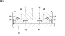
- FIG. 5 is a cross-sectional view showing another modified example of the bush portions 51 and 52 (sliding bearing 50).
- the notch portion 61 is provided in the center in the radial direction of the first bush portion 51, and the notch portion 62 is provided in the center in the radial direction of the second bush portion 52.
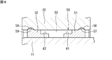
- FIG. 6 is a cross-sectional view showing still another modified example of the bush portions 51 and 52 (sliding bearing 50).
- the notch portion 61 is provided on the radially outer side of the first bush portion 51
- the notch portion 62 is provided on the radially outer side of the second bush portion 52.
- a space 55 including notches 61 and 62 is formed between the first bush portion 51 and the second bush portion 52, and a lot of grease is formed in the space 55. Can be stored.
- FIG.4 and FIG.6 demonstrated the case where notch part (61, 62) was formed in both the 1st bush part 51 and the 2nd bush part 52, notch It is good also considering only the any one of a pair of bush parts 51 and 52 as the object which provides a part.
- At least one bush portion of the first bush portion 51 and the second bush portion 52 is between the other bush portion.
- a notch 61 (62) for widening the space 55 to be formed is provided. According to such a sliding bearing 50 including the bush portions 51 and 52, it is possible to increase a region in which grease can be stored, and to further ensure good lubricity over a long period of time with the grease.
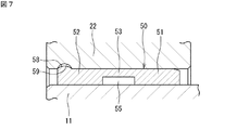
- FIG. 7 is a cross-sectional view showing still another modified example of the bush portions 51 and 52 (sliding bearing 50).
- the 1st bush part 51 and the 2nd bush part 52 are separate bodies, but in the form shown in FIG. 7, the 1st bush part 51 and the 2nd bush part 52 are connected, and are united.
- the sliding bearing 50 includes a first bush portion 51 that is in sliding contact with the shaft body 11, a second bush portion 52 that is in sliding contact with the shaft body 11, and the first bush portion 51 and the second bush portion 52.
- the connecting shaft body 11 has a cylindrical connecting portion 53 that is not in contact with the connecting shaft body 11.
- a grease retaining space 55 is formed between the first bush portion 51 and the second bush portion 52 and inside the connecting portion 53 in the radial direction.
- the number of parts can be reduced, and the operation of attaching the slide bearing 50 to the second spring seat 22 is facilitated. That is, the sliding bearing 50 shown in FIG. 7 has a cylindrical connecting portion 53 interposed between the first bush portion 51 and the second bush portion 52 as a connecting bush portion. The part 51 and the second bush part 52 are integrated.
- FIG. 8 is a perspective view showing a slide bearing 50 according to another embodiment.
- This slide bearing 50 is the same as the slide bearing 50 shown in FIG. 3 in that it has a first bush portion 51 and a second bush portion 52, but in addition, it is interposed between the bush portions 51, 52.
- the connecting bush portion 70 is further provided.
- the connection bush part 70 of the form shown in FIG. 8 is a plurality of column parts 71 provided at intervals in the circumferential direction, and includes an annular first bush part 51 and an annular second bush part 52. Partially connected.
- a space 55 for holding grease is formed between the first bush portion 51 and the second bush portion 52 and between the column portions 71 and 71 adjacent in the circumferential direction.
- the space 55 is configured to be partitioned by the pillar portion 71.
- FIG. 9 is a perspective view showing a modification of the slide bearing 50 shown in FIG.
- this sliding bearing 50 is compared with the sliding bearing 50 shown in FIG. 8, in the sliding bearing 50 shown in FIG. 9, the number of the column parts 71 is large, but others are the same.
- the dimensions of the first bush part 51, the second bush part 52, and the pillar part 71 are set so that the volume (total) of the space 55 is equivalent to the form shown in FIG. .
- FIG. 10 is a perspective view showing a slide bearing 50 according to another embodiment.
- This slide bearing 50 is the same as the slide bearing 50 shown in FIG. 3 in that it has a first bush portion 51 and a second bush portion 52, but in addition, it is interposed between these bush portions 51 and 52.
- the connecting bush portion 70 is further provided.
- the connection bush part 70 of the form shown in FIG. 10 includes an annular third bush part 73 and a plurality of column parts 72.
- the third bush portion 73 is provided between the annular first bush portion 51 and the annular second bush portion 52.
- Each column part 72 connects the first bush part 51 and the third bush part 73, and also connects the third bush part 73 and the second bush part 52. That is, the column part 72 has connected between the bush parts adjacent to an axial direction.
- a plurality of column portions 72 are provided at intervals (equal intervals) in the circumferential direction.
- the space 55 between the first bush portion 51 and the third bush portion 73 and adjacent column portions 71 and 71 in the circumferential direction is a grease retaining space 55, and the second bush portion 52 is provided.
- a space 55 for retaining the grease is formed between the first bush portion 73 and the third bush portion 73 and between the column portions 71 and 71 adjacent in the circumferential direction.
- FIG. 11 is a perspective view showing a modification of the plain bearing 50 shown in FIG.
- the sliding bearing 50 shown in FIG. 11 has a plurality (two) of third bush portions 73. Note that at least one third bush portion 73 may be provided between the first bush portion 51 and the second bush portion 52. And these bush parts are connected by the pillar part 72.
- FIG. 11 is a perspective view showing a modification of the plain bearing 50 shown in FIG.
- a space 55 between the first bush portion 51 and the third bush portion 73 and between the column portions 72, 72 adjacent in the circumferential direction is a grease holding space 55.
- a space 55 for retaining grease is also formed between the column portions 72 and 72 adjacent in the circumferential direction.
- the first bush portion 51, the second bush portion 52, the third bush portion 73, and the volume (total) of the space 55 are the same as those in the embodiment shown in FIG. 8.
- Each dimension of the column part 72 is set.
- the plain bearing 50 is connected to the bush portions 51 and 52 in addition to the first bush portion 51 and the second bush portion 52.
- the bush portion 70 is further provided, and the connecting bush portion 70 integrates the first bush portion 51 and the second bush portion 52. Since the 1st bush part 51 and the 2nd bush part 52 are integrated, the operation
- connection bush part 70 is also in a state of being tightly fitted to the second spring seat 22, and also in sliding contact with the shaft body 11 on the inner peripheral surface of the connection bush part 70.
- the contact area can be expanded and the contact surface pressure in the slide bearing 50 can be reduced.
- a convex portion 58 is provided on the outer peripheral surface 52 b of the second bush portion 52. This convex portion 58 is the same as the convex portion 58 in the form shown in FIG.
- the convex part 58 should just be provided only in either one.
- the pillar part 71 (72) is formed with the groove
- the grease can be moved between the spaces 55 and 55.
- the third bush portion 73 is not shown, but a groove or a hole is formed along the axial direction parallel to the center line of the slide bearing 50, and the axial direction The adjacent spaces 55 and 55 may be communicated with each other through this groove or hole. In this case, the grease can be moved between the spaces 55 and 55.
- the column part 71 (72) has a linear shape along the axial direction parallel to the centerline of the sliding bearing 50, it has a linear shape along the direction which inclines in the said axial direction. Also good. Further, the shape of the space 55 is also a linear shape along the circumferential direction, but may be an inclined shape.
- the first spring seat 21 has an inner cylindrical portion 21 b positioned on the radially inner side of the coil spring 15 and an outer cylindrical portion 21 c positioned on the radially outer side of the coil spring 15. .
- a gap is generated between the outer peripheral surface of the coil spring 15 and the inner peripheral surface of the outer cylindrical portion 21c.
- the outer peripheral surface of the coil spring 15 contacts the inner peripheral surface of the outer cylindrical portion 21c.
- the inner cylindrical portion 21b of the first spring seat 21 has a function of guiding the deformation when the coil spring 15 is elastically deformed so that the diameter of the coil spring 15 is reduced. It functions as a biting outer ring member.
- the second spring seat 22 also has an inner cylindrical portion 22 b and an outer cylindrical portion 22 c and has the same function as the first spring seat 21.
- the outer member 23 is a cylindrical member, and has an inner peripheral surface 19a having a small diameter, an inner peripheral surface 19b having a large diameter, and a tapered surface 19c connecting the inner peripheral surfaces 19a and 19b on the inner periphery thereof. ing.
- the outer ring 41 of the rolling bearing 40 is fitted and attached to the small-diameter inner peripheral surface 19a.
- a first spring seat 21, a second spring seat 22, and a coil spring 15 are arranged on the radially inner side of the large-diameter inner peripheral surface 19b.
- the washer 45 and the thrust bush 46 are interposed between the outer ring 41 and the first spring seat 21, and the washer 45 and the thrust bush 46 are arranged in the radial direction of the small-diameter inner peripheral surface 19a. It is provided inside.
- the rolling bearing 40 When the clutch device 10 is assembled, the rolling bearing 40 is fitted into the small-diameter inner peripheral surface 19a from one side in the axial direction.
- the other first spring seat 21, second spring seat 22, coil spring 15, and the like are mounted after the washer 45 and the thrust bush 46 are inserted from the other side in the axial direction.
- the washer 45 and the thrust bushing 46 need to be advanced from the large-diameter inner peripheral surface 19b to the small-diameter inner peripheral surface 19a and attached to the small-diameter inner peripheral surface 19a. Therefore, the tapered surface 19c functions as a guide surface at this time. That is, the tapered surface 19c can prevent the annular washer 45 and the thrust bushing 46 from being inclined or caught on the way.
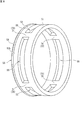
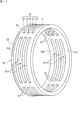
- the bush 93 provided in the prior art clutch device has a ring shape as shown in FIG. 13, but is cut off at one location in the circumferential direction to form a C shape. Further, since the bush 93 is in sliding contact with a part of the outer member 99 on the outer peripheral surface thereof, grease is provided to ensure lubricity. In addition to attaching the grease to the bush 93 when the clutch device 90 is assembled, the bush 93 has the interrupted portion 93a as described above (see FIG. 13), so that the grease is accumulated in the portion 93a. be able to.
- the interrupted portion 93a of the bush 93 is narrow, and even if the grease is accumulated in the portion 93a, the grease flows out from the portion 93a in the axial direction while the use is continued. There is a risk that grease will be depleted early on the sliding contact surface. When the grease is depleted, the bush 93 is in a poorly lubricated state, and the temperature is abnormally increased or abnormal noise is generated due to frictional heat. Accordingly, the following invention (clutch device) is disclosed for the purpose of ensuring good lubricity over a long period of time with a grease in a sliding bearing of a clutch device.
- the clutch device 10 (see FIG. 1) includes a shaft body 11, an outer rotating body 20 provided on the radially outer side of the shaft body 11, and a relative relationship between the shaft body 11 and the outer rotating body 20. Absorbs rotational fluctuations between the shaft body 11 and the outer rotating body 20 in the locked state, and the clutch portion 30 that selectively switches between a free state that enables rotation and a locked state that disables relative rotation.
- the structure for example, each structure of the sliding bearing 50 demonstrated about each said form is applicable to this clutch apparatus 10.
- a space 55 is formed between the first bush portion 51 and the second bush portion 52 of the sliding bearing 50 between a part of the shaft body 11 and a part of the outer rotating body 20.
- grease can be accumulated and held in the space 55.
- the shaft body 11 and the outer rotating body 20 are supported by the rolling bearing 40 and the sliding bearing 50.
- Grease makes it possible to ensure good lubricity over a long period of time. As a result, it is possible to contribute to extending the life of the clutch device 10.
- the clutch device of the present invention is not limited to the illustrated form, and may be of other forms within the scope of the present invention.
- the cross-sectional shape of the 1st bush part 51 and the cross-sectional shape of the 2nd bush part 52 are made the same, you may differ.
- the rolling bearing 40 was demonstrated as a ball bearing in the said embodiment, the roller bearing which used the rolling element as the roller may be sufficient.
- the clutch part 30 was demonstrated as a one-way clutch which has the needle roller 32 as an engaging element, although not shown in figure, the one-way clutch which used the sprag as an engaging element may be sufficient.
- the combination of the rolling bearing 40 and the sliding bearing 50 is used. 1 may be a sliding bearing, or the other axial bearing shown in FIG. 1 may be a rolling bearing.
- the slide bearing 50 only needs to have a plurality of bush portions, and a space for holding the grease is provided between them. That is, it suffices to have at least the first bush portion 51 and the second bush portion 52, and further has a third bush portion 73 as shown in FIGS. A space 55 may be used.
- the clutch device of the present invention is provided in an alternator has been described, it can also be applied to other devices.
Landscapes
- Engineering & Computer Science (AREA)
- General Engineering & Computer Science (AREA)
- Mechanical Engineering (AREA)
- Rolling Contact Bearings (AREA)
Abstract
Selon l'invention, un dispositif d'embrayage comprend : un corps d'arbre ; un corps rotatif extérieur disposé sur un côté radialement extérieur du corps d'arbre ; une unité d'embrayage permettant de commuter sélectivement entre un état libre dans lequel une rotation relative du corps d'arbre et du corps rotatif extérieur est permise et un état verrouillé dans lequel la rotation relative n'est pas permise ; un ressort hélicoïdal permettant d'absorber la fluctuation de rotation entre le corps d'arbre et le corps rotatif extérieur dans l'état verrouillé ; et un palier permettant de supporter le corps d'arbre et le corps rotatif extérieur de sorte que la rotation relative soit permise dans l'état libre. L'unité d'embrayage est disposée du côté radialement extérieur du corps d'arbre. Le ressort hélicoïdal permettant d'absorber la fluctuation de rotation est disposé du côté radialement extérieur de l'unité d'embrayage.
Priority Applications (3)
| Application Number | Priority Date | Filing Date | Title |
|---|---|---|---|
| US16/099,399 US20190226535A1 (en) | 2016-05-23 | 2017-05-23 | Clutch device |
| CN201780031477.8A CN109154338A (zh) | 2016-05-23 | 2017-05-23 | 离合器装置 |
| DE112017002618.0T DE112017002618T5 (de) | 2016-05-23 | 2017-05-23 | Kupplungsvorrichtung |
Applications Claiming Priority (4)
| Application Number | Priority Date | Filing Date | Title |
|---|---|---|---|
| JP2016102262 | 2016-05-23 | ||
| JP2016-102262 | 2016-05-23 | ||
| JP2016-188330 | 2016-09-27 | ||
| JP2016188330A JP2017211077A (ja) | 2016-05-23 | 2016-09-27 | クラッチ装置 |
Publications (1)
| Publication Number | Publication Date |
|---|---|
| WO2017204183A1 true WO2017204183A1 (fr) | 2017-11-30 |
Family
ID=60412806
Family Applications (1)
| Application Number | Title | Priority Date | Filing Date |
|---|---|---|---|
| PCT/JP2017/019108 Ceased WO2017204183A1 (fr) | 2016-05-23 | 2017-05-23 | Dispositif d'embrayage |
Country Status (1)
| Country | Link |
|---|---|
| WO (1) | WO2017204183A1 (fr) |
Cited By (2)
| Publication number | Priority date | Publication date | Assignee | Title |
|---|---|---|---|---|
| EP3627003A1 (fr) * | 2018-09-20 | 2020-03-25 | Rolls-Royce Deutschland Ltd & Co KG | Système d'engrenage épicyclique et moteur de turbine à gaz |
| JP2020190331A (ja) * | 2019-05-17 | 2020-11-26 | 三ツ星ベルト株式会社 | プーリ構造体 |
Citations (8)
| Publication number | Priority date | Publication date | Assignee | Title |
|---|---|---|---|---|
| JPS51113538U (fr) * | 1975-03-12 | 1976-09-14 | ||
| JPS6071730U (ja) * | 1983-10-22 | 1985-05-21 | 株式会社イワキ | 軸受の取付構造 |
| JP2002070865A (ja) * | 2000-08-31 | 2002-03-08 | Komatsu Ltd | ジャーナル軸受 |
| JP2010019313A (ja) * | 2008-07-09 | 2010-01-28 | Ntn Corp | プーリユニット |
| JP2013504028A (ja) * | 2009-09-17 | 2013-02-04 | ザ ゲイツ コーポレイション | アイソレータ・デカップラ |
| JP2015518946A (ja) * | 2012-06-04 | 2015-07-06 | ゲイツ コーポレイション | アイソレータ・デカップラ |
| JP2015534008A (ja) * | 2012-09-10 | 2015-11-26 | ゼン エス/エイ インダストリア メタルルジカZen S/A Industria Metalurgica | フリーホイールシステム及び振動減衰機構を有するデカップラ |
| JP2016017593A (ja) * | 2014-07-09 | 2016-02-01 | 日本精工株式会社 | 一方向クラッチ内蔵型プーリ装置 |
-
2017
- 2017-05-23 WO PCT/JP2017/019108 patent/WO2017204183A1/fr not_active Ceased
Patent Citations (8)
| Publication number | Priority date | Publication date | Assignee | Title |
|---|---|---|---|---|
| JPS51113538U (fr) * | 1975-03-12 | 1976-09-14 | ||
| JPS6071730U (ja) * | 1983-10-22 | 1985-05-21 | 株式会社イワキ | 軸受の取付構造 |
| JP2002070865A (ja) * | 2000-08-31 | 2002-03-08 | Komatsu Ltd | ジャーナル軸受 |
| JP2010019313A (ja) * | 2008-07-09 | 2010-01-28 | Ntn Corp | プーリユニット |
| JP2013504028A (ja) * | 2009-09-17 | 2013-02-04 | ザ ゲイツ コーポレイション | アイソレータ・デカップラ |
| JP2015518946A (ja) * | 2012-06-04 | 2015-07-06 | ゲイツ コーポレイション | アイソレータ・デカップラ |
| JP2015534008A (ja) * | 2012-09-10 | 2015-11-26 | ゼン エス/エイ インダストリア メタルルジカZen S/A Industria Metalurgica | フリーホイールシステム及び振動減衰機構を有するデカップラ |
| JP2016017593A (ja) * | 2014-07-09 | 2016-02-01 | 日本精工株式会社 | 一方向クラッチ内蔵型プーリ装置 |
Cited By (4)
| Publication number | Priority date | Publication date | Assignee | Title |
|---|---|---|---|---|
| EP3627003A1 (fr) * | 2018-09-20 | 2020-03-25 | Rolls-Royce Deutschland Ltd & Co KG | Système d'engrenage épicyclique et moteur de turbine à gaz |
| US11401985B2 (en) | 2018-09-20 | 2022-08-02 | Rolls-Royce Deutschland Ltd & Co Kg | Epicyclic gear system and gas turbine engine |
| JP2020190331A (ja) * | 2019-05-17 | 2020-11-26 | 三ツ星ベルト株式会社 | プーリ構造体 |
| JP7281428B2 (ja) | 2019-05-17 | 2023-05-25 | 三ツ星ベルト株式会社 | プーリ構造体 |
Similar Documents
| Publication | Publication Date | Title |
|---|---|---|
| US7000749B2 (en) | Ratchet one-way clutch, and stator apparatus using the same | |
| CN105074282A (zh) | 单向离合器内置型带轮装置 | |
| JP5202061B2 (ja) | 係合解除可能なプーリ装置 | |
| JP2017211077A (ja) | クラッチ装置 | |
| WO2017204183A1 (fr) | Dispositif d'embrayage | |
| JP3652207B2 (ja) | 一方向クラッチ内蔵型回転伝達装置 | |
| JP2010281375A (ja) | 逆入力遮断クラッチ | |
| US10584743B2 (en) | Needle roller thrust bearing | |
| JP4905001B2 (ja) | 一方向クラッチ及び動力伝達装置 | |
| JP2000337405A (ja) | 一方向クラッチ内蔵型プーリ装置 | |
| JP2010185547A (ja) | 一方向クラッチ内蔵型プーリ装置 | |
| JP3632262B2 (ja) | スラストころ軸受 | |
| JP2012172790A (ja) | 一方向クラッチ内蔵型プーリ装置 | |
| JP3724506B2 (ja) | 一方向クラッチ内蔵型プーリ装置 | |
| JP4893997B2 (ja) | 一方向クラッチ | |
| JP2000283267A (ja) | オルタネータ用一方向クラッチ内蔵型プーリ装置 | |
| JP4899343B2 (ja) | 一方向クラッチ内蔵型プーリ装置 | |
| JP2019094994A (ja) | クラッチ装置 | |
| JP2000291782A (ja) | オルタネータ用一方向クラッチ内蔵型プーリ装置 | |
| JP4389581B2 (ja) | クラッチ内蔵型プーリユニット | |
| JP2007100755A (ja) | 一方向クラッチ内蔵型プーリ装置 | |
| JP2007198504A (ja) | 一方向クラッチ及び一方向クラッチ内蔵型プーリ装置 | |
| JP2006307922A (ja) | 一方向クラッチ | |
| JP2007113787A (ja) | 一方向クラッチおよびそれを備える動力伝達装置 | |
| JPH11118026A (ja) | オルタネータ用ローラクラッチ内蔵型プーリ装置 |
Legal Events
| Date | Code | Title | Description |
|---|---|---|---|
| 121 | Ep: the epo has been informed by wipo that ep was designated in this application |
Ref document number: 17802769 Country of ref document: EP Kind code of ref document: A1 |
|
| 122 | Ep: pct application non-entry in european phase |
Ref document number: 17802769 Country of ref document: EP Kind code of ref document: A1 |