WO2017204232A1 - 車載ゲートウェイ装置及び車載ゲートウェイシステム - Google Patents
車載ゲートウェイ装置及び車載ゲートウェイシステム Download PDFInfo
- Publication number
- WO2017204232A1 WO2017204232A1 PCT/JP2017/019286 JP2017019286W WO2017204232A1 WO 2017204232 A1 WO2017204232 A1 WO 2017204232A1 JP 2017019286 W JP2017019286 W JP 2017019286W WO 2017204232 A1 WO2017204232 A1 WO 2017204232A1
- Authority
- WO
- WIPO (PCT)
- Prior art keywords
- vehicle
- data
- communication
- data source
- monitoring
- Prior art date
- Legal status (The legal status is an assumption and is not a legal conclusion. Google has not performed a legal analysis and makes no representation as to the accuracy of the status listed.)
- Ceased
Links
Images





Classifications
-
- H—ELECTRICITY
- H04—ELECTRIC COMMUNICATION TECHNIQUE
- H04L—TRANSMISSION OF DIGITAL INFORMATION, e.g. TELEGRAPHIC COMMUNICATION
- H04L12/00—Data switching networks
- H04L12/28—Data switching networks characterised by path configuration, e.g. LAN [Local Area Networks] or WAN [Wide Area Networks]
- H04L12/46—Interconnection of networks
-
- H—ELECTRICITY
- H04—ELECTRIC COMMUNICATION TECHNIQUE
- H04M—TELEPHONIC COMMUNICATION
- H04M11/00—Telephonic communication systems specially adapted for combination with other electrical systems
-
- H—ELECTRICITY
- H04—ELECTRIC COMMUNICATION TECHNIQUE
- H04W—WIRELESS COMMUNICATION NETWORKS
- H04W24/00—Supervisory, monitoring or testing arrangements
- H04W24/08—Testing, supervising or monitoring using real traffic
-
- H04W4/04—
-
- H—ELECTRICITY
- H04—ELECTRIC COMMUNICATION TECHNIQUE
- H04W—WIRELESS COMMUNICATION NETWORKS
- H04W4/00—Services specially adapted for wireless communication networks; Facilities therefor
- H04W4/30—Services specially adapted for particular environments, situations or purposes
- H04W4/40—Services specially adapted for particular environments, situations or purposes for vehicles, e.g. vehicle-to-pedestrians [V2P]
- H04W4/44—Services specially adapted for particular environments, situations or purposes for vehicles, e.g. vehicle-to-pedestrians [V2P] for communication between vehicles and infrastructures, e.g. vehicle-to-cloud [V2C] or vehicle-to-home [V2H]
-
- H—ELECTRICITY
- H04—ELECTRIC COMMUNICATION TECHNIQUE
- H04W—WIRELESS COMMUNICATION NETWORKS
- H04W48/00—Access restriction; Network selection; Access point selection
- H04W48/18—Selecting a network or a communication service
-
- H—ELECTRICITY
- H04—ELECTRIC COMMUNICATION TECHNIQUE
- H04L—TRANSMISSION OF DIGITAL INFORMATION, e.g. TELEGRAPHIC COMMUNICATION
- H04L12/00—Data switching networks
- H04L12/28—Data switching networks characterised by path configuration, e.g. LAN [Local Area Networks] or WAN [Wide Area Networks]
- H04L12/40—Bus networks
-
- H—ELECTRICITY
- H04—ELECTRIC COMMUNICATION TECHNIQUE
- H04L—TRANSMISSION OF DIGITAL INFORMATION, e.g. TELEGRAPHIC COMMUNICATION
- H04L12/00—Data switching networks
- H04L12/28—Data switching networks characterised by path configuration, e.g. LAN [Local Area Networks] or WAN [Wide Area Networks]
- H04L12/40—Bus networks
- H04L2012/40208—Bus networks characterized by the use of a particular bus standard
- H04L2012/40215—Controller Area Network CAN
Definitions
- Embodiments of the present invention relate to an in-vehicle gateway technology for connecting a data source in a moving body such as a vehicle to a network outside the moving body.
- An in-vehicle gateway that can connect a data source in a moving body such as a vehicle stably to a network outside the moving body, and select an appropriate communication path according to the data source in the moving body to connect to the network outside the moving body. Providing equipment.
- the in-vehicle gateway device of the embodiment is an in-vehicle gateway device that is connected to a plurality of data sources in a mobile body and can be connected to a network outside the mobile body.
- the in-vehicle gateway device includes a communication device including an external communication interface that connects to a network outside the mobile body in each of a plurality of different external communication methods, and an internal communication interface that connects to a plurality of data sources. And a control device for transmitting data collected from the data source to a network outside the mobile body.
- the control device includes a communication control unit that performs communication connection with a network outside the mobile body in each of the plurality of external communication methods, a storage unit that stores Config information set for each data source, and a plurality of the external communication methods.
- a communication path selection unit that selects a communication path for each data source from within, and monitors the data output from each data source, and transmits the data to a network outside the moving body via the communication path selected according to the data source And a monitoring control unit.
- the Config information includes communication connection Config setting information including a priority setting in which a plurality of the external communication methods are arranged in a predetermined priority order.
- the communication path selection unit switches the communication path for each data source according to each communication connection state of the plurality of external communication methods based on the communication connection config setting information.
- 1 is a network configuration diagram inside and outside a vehicle to which an in-vehicle gateway device of a first embodiment is applied. It is a figure which shows the structural block of the vehicle-mounted gateway apparatus of 1st Embodiment. It is a figure which shows an example of the communication connection Config setting information of 1st Embodiment. It is a figure which shows an example of the vehicle-mounted LANConfig setting information of 1st Embodiment. It is a figure which shows an example of the sensor apparatus Config setting information of 1st Embodiment. It is a figure which shows an example of the log config setting information of 1st Embodiment. It is a flowchart which shows the update registration process of Config setting information of 1st Embodiment.
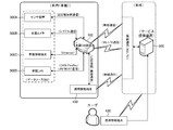
- FIG. 1 is a network configuration diagram inside and outside a vehicle to which an in-vehicle gateway device 100 (hereinafter referred to as an in-vehicle GW device) of the first embodiment is applied.
- the in-vehicle GW apparatus 100 is an in-vehicle device that is directly connected to the in-vehicle data source 300 or connected to an in-vehicle network to which the data source 300 is connected.
- a vehicle will be described as an example, but the present invention can also be applied to other moving objects (such as trains, robots or flying objects operated automatically or wirelessly).
- the in-vehicle GW apparatus 100 can be connected to a network outside the vehicle, and is configured as a network node that relays between the inside and outside the vehicle.
- the in-vehicle GW apparatus 100 includes communication interfaces for wireless communication conforming to a wireless LAN standard such as Wi-Fi via an access point, and mobile phone communication such as 3G and LTE (Long Term Evolution) relaying a base station. Yes.
- the in-vehicle GW apparatus 100 can be connected to an external network outside the vehicle through a plurality of communication paths (external communication methods).
- the outside-vehicle network is, for example, an IP (Internet Protocol) network.
- the in-vehicle GW apparatus 100 can be connected to the service providing apparatus 500 via the IP network.
- the in-vehicle GW apparatus 100 can upload various data acquired from the in-vehicle data source 300 to the service providing apparatus 500 and receive various data from the service providing apparatus 500.
- the in-vehicle GW apparatus 100 can also be connected to a network outside the vehicle via a portable information terminal 400 provided with a Wi-Fi or 3G / LTE communication interface.
- the in-vehicle GW apparatus 100 can be connected to the portable information terminal 400 by USB or by short-range communication based on a standard such as wireless communication or Bluetooth (registered trademark) / NFC.
- the portable information terminal 400 is a mobile device having a communication function such as a multi-function mobile phone such as a smartphone, a mobile phone, and a tablet terminal. Further, the user can directly connect to the service providing apparatus 500 from the portable information terminal 400 or a computer apparatus having other communication functions regardless of the in-vehicle GW apparatus 100.
- the in-vehicle GW apparatus 100 can be connected to the in-vehicle data source 300 directly or via an existing in-vehicle network.
- the data source 300 includes, for example, a microphone (sound collecting device), a sensor device 300A such as a human sensor or a vital sensor worn by a user, a drive recorder equipped with a camera (photographing device), an in-vehicle camera for photographing the inside of the vehicle, and the like.
- There are an in-vehicle information terminal 300C such as a navigation system provided with display means such as an in-vehicle camera 300B and a liquid crystal display device, an in-vehicle LAN 300D, and the like.
- a vehicle control system vehicle ECU, a multimedia system audio device, and the like are data sources.
- the in-vehicle GW apparatus 100 performs data communication using a different communication method for each data source 300 according to the communication method provided in each data source 300 or in-vehicle network.
- the sensor device 300A performs data communication by short-range wireless communication.
- the in-vehicle camera 300B performs data communication by serial (UART) communication (RS232C, RS422, RS485) connected to the in-vehicle GW apparatus 100 with a cable.
- the in-vehicle information terminal 300C performs data communication by Ethernet communication connected by a LAN cable.
- the in-vehicle camera 300B can include an interface board including, for example, a UART circuit and a MIDI terminal.
- the in-vehicle camera 300B can output and display the captured video on the in-vehicle information terminal 300C and other displays via the MIDI terminal.
- the in-vehicle LAN 300D has an in-vehicle network built in a communication system such as CAN (controller area network), FlexRay, LIN, and MOST (media oriented systems transport).
- the in-vehicle GW apparatus 100 is connected to each of one or a plurality of in-vehicle networks constituting the in-vehicle LAN 300D, and performs data communication by each communication method.
- FIG. 2 is a diagram illustrating a configuration block of the in-vehicle GW apparatus 100.
- the in-vehicle GW apparatus 100 has, as a hardware configuration, a control that controls the communication device 110 that forms a communication interface with each data source 300 (including the in-vehicle LAN 300D) and the portable information terminal 400, and the entire in-vehicle GW apparatus 100.
- Device 120 includes the in-vehicle GW apparatus 100.
- the communication device 110 includes an in-vehicle communication (internal communication) interface 111 such as Ethernet, CAN, UART, USB, and short-range wireless communication, and an out-of-vehicle communication (external communication) interface 112 such as wireless communication and mobile phone communication.
- an in-vehicle communication (internal communication) interface 111 such as Ethernet, CAN, UART, USB, and short-range wireless communication
- an out-of-vehicle communication (external communication) interface 112 such as wireless communication and mobile phone communication.
- the in-vehicle communication interface can be configured to include a wireless communication function with the portable information terminal 400 for connection to an external network via the portable information terminal 400.
- the control device 120 is configured to include each functional unit that mainly operates by software.
- the control device 120 can control each data source 300. For example, sensor control (operation and data detection) of the sensor device 300A, imaging control (including video output control) of the in-vehicle camera, and terminal control of the in-vehicle information terminal 300C can be performed.
- control device 120 can output the data received from the external network to the data source 300, or control the data source 300 based on the received data.
- one or both of the data sources 300 can be controlled between the data sources 300. For example, it is possible to perform control for displaying detection data acquired by the sensor device 300A and video captured by the in-vehicle camera 300B on the display of the in-vehicle information terminal 300C.
- the control device 120 of this embodiment includes an in-vehicle communication control unit 121, an out-of-vehicle communication control unit 122, and a gateway control unit (GW control unit) 123.
- GW control unit gateway control unit
- the in-vehicle GW apparatus 100 is installed with respective device drivers such as wireless communication, mobile phone communication, UART, USB, and short-range wireless communication.
- the in-vehicle communication control unit 121 and the out-of-vehicle communication control unit 122 perform communication control via the in-vehicle communication interface 111 and the out-of-vehicle communication interface 112 through each device driver.
- the in-vehicle communication control unit 121 can also control communication with, for example, the in-vehicle LAN 300D without using a device driver.
- the out-of-vehicle communication control unit 122 can perform access point registration processing for wireless communication such as Wi-Fi.
- the out-of-vehicle communication control unit 122 can detect and register access points at various locations as the vehicle physically moves.
- the GW control unit 123 includes a network control unit 123A, a communication control unit 123B, and a storage unit 123C.
- the network control unit 123A includes a routing control unit 1231, a protocol conversion unit 1232, and a security unit 1233.
- the routing control unit 1231 performs routing control when transmitting data collected from each data source 300 (including the in-vehicle LAN 300D) to the outside network, and transmits data received from the outside network to each data source 300. Perform routing control. In addition, routing control in data communication between the data sources 300 in the in-vehicle network is also performed.
- the protocol conversion unit 1232 performs a protocol conversion process between different communication methods corresponding to each data source.
- a communication method for each data source 300 can be stored in advance as a protocol conversion table. For example, protocol conversion is performed when data received from an external network is transmitted to the data source 300.
- the security unit 1233 performs communication setting and communication processing of SSL (Secure Sockets Layer) / TLS (Transport Layer Layer Security) protocol. SSL / TLS communication can be set for each data source 300. When data is transmitted from the in-vehicle network to the external network, the security unit 1233 checks whether SSL / TLS is set and performs encryption processing. It can be carried out.
- SSL Secure Sockets Layer
- TLS Transport Layer Layer Security
- the storage unit 123C stores various data processed by the control device 120, information used for each process, data and information received from a network outside the vehicle, and the like.
- the storage unit 123 ⁇ / b> C is built in the in-vehicle GW device 100, but the storage unit 123 ⁇ / b> C may be externally attached to the in-vehicle GW device 100, for example.
- the in-vehicle GW apparatus 100 can include a connection port (such as a USB port) for connecting to the external storage unit 123C.
- the communication control unit 123B includes a communication state monitoring unit 1234, a communication path selection unit 1235, a monitoring control unit 1236, and a Config setting control unit 1237. Based on the Config setting information, the communication control unit 123B performs communication route selection control, data monitoring control, and data transmission control for transmitting data collected from the data source 300 to the external network.
- 3 to 6 are diagrams illustrating an example of Config setting information according to the present embodiment.
- FIG. 3 is a diagram showing an example of the communication connection config setting information, which is used for communication path selection control of the communication path selection unit 1235.
- the communication connection config setting includes a communication path setting at the time of data transmission from the in-vehicle network to the outside network and a communication path setting at the time of data reception from the outside network to the in-vehicle network.
- the in-vehicle GW apparatus 100 of this embodiment is mounted on a moving body such as a vehicle. For this reason, for example, the in-vehicle GW apparatus 100 is assigned a dynamic IP address as a network node. The in-vehicle GW apparatus 100 actively connects to and establishes a connection with the service providing apparatus 500 of the outside-vehicle network when transmitting and receiving data.
- the communication connection for data reception from the outside-vehicle network mainly includes a communication path for configuration setting and a communication path for large-scale data distribution.
- the Config setting information can be received from the service providing apparatus 500 as described later.
- the large-scale data distribution is, for example, map data used for the in-vehicle information terminal 300C.
- the communication connection settings include automatic setting and / or priority setting.
- the in-vehicle GW apparatus 100 can be connected to a network outside the vehicle via a plurality of communication scheme paths. For example, one of the three routes of Wi-Fi, via a portable information terminal, and 3G / LTE can be selected, and priority can be set for the three routes. Also, the priority of “automatic” can be arbitrarily determined in advance, for example, Wi-fi> via mobile information terminal> 3G / LTE.
- the communication connection during data transmission from the in-vehicle network to the outside network includes, for example, a vital information upload communication path, a vehicle information upload communication path, and a log information upload communication path.
- photographed with the vehicle-mounted camera 300B can also be included.
- automatic setting and / or priority setting can be performed.
- the communication connection config setting includes a setting for enabling / disabling each of a plurality of communication paths used by the in-vehicle GW apparatus 100.
- Wi-Fi communication use settings, 3G / LTE communication use settings, and portable information terminal communication use settings can be set to valid (ON) / invalid (OFF).
- priority can be given to valid / invalid of the communication use setting, and control can be performed so as not to select the communication path set to invalid.
- the communication connection config setting includes URL designation (registration) of the service providing apparatus 500 that is a connection destination of the outside-vehicle network.
- URL designation registration
- the in-vehicle GW apparatus 100 is connected to a plurality of service providing apparatuses 500, a plurality of URLs are designated.
- each data node 300 may be connected to a different service providing apparatus 500. That is, it is possible to associate the service providing device 500 to be connected for each data source and control the specific service providing device 500 to transmit the data acquired from the specific data source.
- FIG. 4 is a diagram showing an example of in-vehicle LANConfig setting information.
- the in-vehicle LANConfig setting information is used for monitoring control by the monitoring control unit 1236.
- the in-vehicle LAN 300D can output vehicle information monitored by the vehicle ECU to the in-vehicle GW apparatus 100.
- the in-vehicle LANConfig setting information includes setting information such as a vehicle information transfer (upload) cycle, an average vehicle speed threshold, and a driving time threshold. Moreover, ON / OFF setting information for selecting vehicle information to be transmitted to the service providing apparatus 500 is also included. For example, transmission ON / OFF of vehicle information such as vehicle speed, engine speed, water temperature, fuel consumption, travel distance, and select lever position can be set.
- FIG. 5 is a diagram illustrating an example of the sensor device Config setting information.
- the sensor device Config setting information is used for monitoring control by the monitoring control unit 1236.
- the sensor device 300A can measure or / and calculate a user's heart rate, pulse interval, blood pressure, and the like and output the measured value to the in-vehicle GW apparatus 100.
- the sensor device Config setting information includes setting information such as a vital information transfer (upload) cycle, a heart rate transfer threshold, and a heart rate abnormality threshold.
- ON / OFF setting information for selecting vital information to be transmitted to the service providing apparatus 500 is also included. For example, transmission ON / OFF of each vital information such as heart rate, pulse interval, pulse wave propagation time, amplitude value can be set.
- FIG. 6 is a diagram illustrating an example of the log config setting information.
- the GW control unit 123 can collect a log indicating normality / abnormality of each process of the entire control device 120. Each unit included in the GW control unit 123 generates a log for each process and stores the log in the storage area. Log Config setting information sets the timing for data transmission of the accumulated log information to the service providing apparatus 500.
- the Config setting control unit 1237 sets (updates) the Config setting information input to the control device 120 in a predetermined storage area so that the communication path selection unit 1235 and the monitoring control unit 1236 can use them.
- the Config setting information can be set via the in-vehicle information terminal 300C.
- the Config setting control unit 1237 can display, for example, a Config setting input screen on the display of the in-vehicle information terminal 300 ⁇ / b> C, and can store the Config setting information input by the user from the input screen.
- the Config setting control unit 1237 uploads the set (updated) Config setting information to the service providing apparatus 500 at a predetermined timing and a predetermined communication path. To do.
- the Config setting information can be set by the service providing apparatus 500.
- the user can connect to the service providing apparatus 500 from the portable information terminal 400, and the service providing apparatus 500 can provide the same Config setting function as the Config setting control unit 1237.
- the service providing apparatus 500 can display the Config setting input screen on the display of the portable information terminal 400, and can store the Config setting information input by the user from the input screen in a storage area in the service providing apparatus 500. Then, the service providing apparatus 500 transmits the set Config setting information based on the Config acquisition request from the in-vehicle GW apparatus 100.
- the Config setting control unit 1237 updates the Config setting information received from the service providing apparatus 500.
- FIG. 7 is a flowchart showing an update registration process for Config setting information.
- the user can connect to the service providing apparatus 500 from the portable information terminal 400 and register (update) the Config setting information for each user through the Config setting function provided by the service providing apparatus 500 (S501, S601). That is, the Config setting information can be updated and registered on the outside-vehicle network side.
- the in-vehicle GW apparatus 100 can be activated by receiving power supply from a vehicle battery or the like in conjunction with ON / OFF of an ignition switch of the vehicle, for example (S101).
- the in-vehicle GW apparatus 100 can connect to the service providing apparatus 500 at the time of activation and acquire the Config setting information that is directly updated / registered in the service providing apparatus 500.
- the in-vehicle GW apparatus 100 performs a communication route selection process based on the communication connection config setting information illustrated in FIG. 3 (S102).
- the in-vehicle GW apparatus 100 (Config setting control unit 1237) transmits a Config setting information acquisition request to the service providing apparatus 500 through the selected communication path (S103).
- the service providing apparatus 500 transmits Config setting information in response to the request (S502).
- the in-vehicle GW apparatus 100 updates the received Config setting information (S104).
- the in-vehicle information terminal 300C can provide the Config setting function.
- the in-vehicle information terminal 300C outputs the Config setting information input by the user to the in-vehicle GW apparatus 100 (S301).
- the in-vehicle GW apparatus 100 updates the input Config setting information (S105).
- the Config setting information is updated and registered on the in-vehicle information terminal 300C side, that is, the in-vehicle network side
- the in-vehicle GW apparatus 100 performs a communication route selection process based on the communication connection Config setting information (S106), and a predetermined timing.
- the Config setting information is uploaded to the service providing apparatus 500 (S107).
- the service providing apparatus 500 updates and registers the Config setting information uploaded from the in-vehicle GW apparatus 100 for each user (S503).
- data communication between the in-vehicle GW apparatus 100 and the service providing apparatus 500 is performed using both a user identification ID and a solid identifier (for example, a MAC address) of the vehicle GW apparatus 100 that are set in advance. It can be carried out.
- the in-vehicle GW apparatus 100 controls the uploaded data to include a solid identifier.
- FIG. 8 is a flowchart showing communication path connection processing.
- the in-vehicle GW apparatus 100 acquires the communication connection Config setting information illustrated in FIG. 3 after activation (S110).
- the in-vehicle GW apparatus 100 performs a communication connection process for a communication path whose connection flag is ON (S111).
- the connection flag is valid (ON) / invalid (OFF) in the communication use setting of each communication method.
- control when there are a plurality of communication paths whose connection flag is ON, control is performed so as to maintain the communication connections of all the plurality of communication paths.
- control is performed so as to maintain the constantly connected state for all the plurality of communication paths whose connection flags are ON.
- an appropriate communication path is selected based on the Config setting according to the communication state of each communication path, and data communication is performed with the network outside the vehicle.
- the communication status monitoring unit 1234 monitors the communication status (connected / blocked) of the communication path whose connection flag is ON (S112).
- the communication state monitoring unit 1234 outputs the communication state of each communication path to the communication control unit 123B.
- the communication state monitoring unit 1234 checks whether or not there is a connection state monitoring end signal (for example, an ignition switch OFF signal of the vehicle) (S113). If the monitoring is not terminated, the process proceeds to step S114, and the communication control unit 123B continues to monitor the communication state when it is determined that the communication path whose connection flag is ON is not blocked (NO in S114).
- step S114 when it is determined that the communication is blocked (YES in S114), the process returns to step S111, and the communication control unit 123B performs the communication connection process again on the communication path that is blocked when the connection flag is ON.
- step S115 if there is an input of a connection state monitoring end signal in step S113 and the monitoring is to be ended, the process proceeds to step S115, where all connected communication paths are blocked.
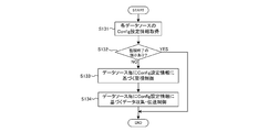
- FIG. 9 is a flowchart showing monitoring control for each data source.
- the communication control unit 123B acquires the Config setting information of each data source 300 (S131).
- the communication state monitoring for example, the presence or absence of a signal for ending the monitoring control of the data source such as an OFF signal of an ignition switch of the vehicle is confirmed (S132).
- the monitoring control is performed based on the Config setting information set for each data source 300.
- the data source 300 can output time-sequential data to the in-vehicle GW apparatus 100.
- the monitoring control based on the Config setting information monitors the data collected from the data source 300.
- the abnormality detection control (S133) detects an abnormality when data exceeding a threshold is detected, and the data source 300 Data collection / transmission control (S134) for transmitting the collected data to the outside-vehicle network is included.
- the monitoring control unit 1236 detects an abnormality for each data source for the data output from the data source 300, and when an abnormality is detected, for example, displays on the in-vehicle information terminal 300C that the abnormality has been detected. Notification processing can be performed.
- FIG. 10 and 11 are diagrams showing an example of the abnormality monitoring control.
- FIG. 10 is a flowchart showing a process flow of abnormality monitoring control based on the in-vehicle LANConfig setting information.
- the monitoring controller 1236 acquires vehicle information from the in-vehicle LAN 300D (vehicle ECU or the like) (S133A).
- the monitoring control unit 1236 calculates the average vehicle speed at the set operation time interval (S133B).
- the monitoring control unit 1236 performs a determination process for determining whether or not the calculated average vehicle speed exceeds the average vehicle speed threshold set in the in-vehicle LANConfig setting information (S133C).
- the abnormality notification flag is ON (NO in S133E)
- the abnormality notification flag is updated to OFF (S133H).
- step S133D if it is determined in step S133D that the calculated average vehicle speed exceeds the average vehicle speed threshold as a result of the determination process (NO in S133D), the abnormality notification flag is updated to ON (S133F). Based on the fact that the abnormality notification flag is ON, the monitoring control unit 1236 performs notification processing to the in-vehicle information terminal 300C (S133G).
- FIG. 11 is a flowchart showing a monitoring control process flow based on the sensor device config setting information.
- the monitoring control unit 1236 acquires vital information from the sensor device 300A (a vital sensor such as a heart rate monitor or a pulse meter) (S1331).
- the monitoring control unit 1236 calculates a heart rate from the acquired vital information (S1332), and stores the calculated heart rate (S1333).
- the monitoring control unit 1236 performs a determination process for determining whether or not the calculated heart rate exceeds the heart rate abnormality threshold value set in the sensor device Config setting information (S1334).
- the abnormality notification flag is OFF (S1336). If the abnormality notification flag is ON (NO in S1336), the abnormality notification flag is updated to OFF (S1339).
- step S1335 if it is determined in step S1335 that the calculated heart rate exceeds the heart rate abnormality threshold value as a result of the determination process (NO in S1335), the abnormality notification flag is updated to ON (S1337).
- the monitoring control unit 1236 performs notification processing to the in-vehicle information terminal 300C based on the fact that the abnormality notification flag is ON (S1338).
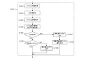
- FIG. 12 is a flowchart showing data collection / transmission control of the monitoring control unit 1236.
- Data collection / transmission control includes data transmission control, communication path selection, and data retention processing when communication is interrupted.
- Data transmission control performs filtering control of data to be transmitted to the outside network and data transmission timing control based on the Config setting information.
- the monitoring control unit 1236 acquires data from each data source 300 (S1341), and performs transmission permission / inhibition determination processing of the collected data based on the Config setting information (S1342).
- a threshold value can be set and only data exceeding the threshold value can be transmitted.
- the monitoring control unit 1236 determines whether or not the data is transmission target data based on the Config setting information (S1343). If the collected data is transmission target data, the corresponding data is transmitted to the outside network. (YES in S1343). On the other hand, if the collected data is not transmission target data, control is performed so that the data is not transmitted to the network outside the vehicle (NO in S1343).
- the timing of data transmission can also be controlled. For example, when the data source 300 outputs data at a short time interval, if all the data is transmitted to the outside-vehicle network, the communication amount increases. Therefore, a data transfer interval longer than the data output time interval of the data source is set based on the Config setting information.
- the monitoring control unit 1236 determines the transmission timing of the data determined as the transmission target data in step S1343 based on the Config setting information (S1344). If the current timing is the transmission timing (transfer cycle) set (YES in S1344), the monitoring control unit 1236 controls the transmission target data to be transmitted to the network outside the vehicle, and if it is not the transmission timing (NO in S1344). The transmission target data is controlled not to be transmitted to the outside network.
- filtering control and data transmission timing control can be performed so that data in which an abnormality is detected by the abnormality detection control is always transmitted to the outside-vehicle network. Further, although filtering control and data transmission timing control are linked as described above, any one of the controls can be applied.
- the communication route selection unit 1235 performs processing for selecting a communication route to the outside network in the data collection / transmission control by the monitoring control unit 1236.
- the communication path selection unit 1235 confirms the communication state based on the communication path monitoring by the communication state monitoring unit 1234 (S1345), and is designated for each data source 300 of data to be transmitted from the communication connection config setting information or Based on the priority order, the currently connected communication path is selected (S1346).
- the monitoring control unit 1236 transmits data collected based on the Config setting information via the out-of-vehicle communication control unit 122 (service provision). (S1348).
- the communication path selection unit 1235 cannot select the currently connected communication path when all the communication paths set in the communication connection config setting information are in the blocked state. Therefore, when the designated or priority communication path cannot be selected (NO in S1347), the monitoring control unit 1236 performs data holding processing when communication is interrupted assuming that data transmission to the outside-vehicle network cannot be performed ( S1349).
- the data holding process at the time of communication interruption is a process of temporarily storing data collected by the monitoring control unit 1236 in time series until a communication path becomes available.
- the monitoring control unit 1236 may transmit the temporarily held data together with the data collected this time to the network outside the vehicle without performing the data transmission at the previous data transmission timing. it can.
- Wi-Fi cannot be used at the data transmission timing and 3G / LTE can be used
- the data is temporarily stored without being transmitted, and when Wi-Fi becomes available, Data can be transmitted to the network outside the vehicle.
- video captured by the in-vehicle camera 300B is transmitted to a network outside the vehicle, since the data capacity is large, video data is temporarily stored until the environment where Wi-Fi can be used.
- -Can transmit in bulk when Fi is available.
- the video data of the in-vehicle camera 300B is a communication path only for Wi-Fi
- the vehicle information of the in-vehicle LAN 300D is Wi-Fi or 3G / LTE.
- Communication paths, and abnormality information detected by abnormality monitoring control can be set as all communication paths (either Wi-Fi, 3G / LTE, or via a portable information terminal).
- the abnormality monitoring control and data collection / transmission control of this embodiment are executed independently. That is, even when various data collected from the data source 300 cannot be transmitted to the outside network due to communication interruption, the abnormality status detected by the abnormality monitoring control is notified to the user via the in-vehicle information terminal 300C. Can do. For this reason, the abnormal status can be notified to the user regardless of the communication state with the network outside the vehicle.
- the service providing apparatus 500 can provide vehicle information and vital information received from the in-vehicle GW apparatus 100 as vehicle operation information and user health management information. For example, when the user connects to the service providing apparatus 500 from the portable information terminal 400, the user can view each monitoring result (monitoring screen) based on the vehicle information and vital information received from the in-vehicle GW apparatus 100.
- the service providing apparatus 500 can provide information to the in-vehicle GW apparatus 100 with respect to the monitoring result of the vehicle information and vital information received from the in-vehicle GW apparatus 100.
- the service providing apparatus 500 performs abnormality detection by setting a threshold different from the abnormality detection control of the monitoring control unit 1236, or a plurality of vehicle information received in addition to the average vehicle speed (engine speed, water temperature, fuel consumption,
- the detection result can be fed back to the in-vehicle GW apparatus 100 by performing complex abnormality detection from the travel distance, the select lever position, and the like.
- the abnormality detection control of the in-vehicle GW apparatus 100 is performed independently of the abnormality detection control of the service providing apparatus 500.
- the abnormality detection control of the service providing apparatus 500 is because vehicle information, vital information, and the like cannot be acquired from the in-vehicle GW apparatus 100 in a state where communication is interrupted.
- the abnormality detection control by the monitoring control unit 1236 is continuously performed even when communication is interrupted.
- the in-vehicle GW apparatus 100 can acquire user's voice information from a sound collection microphone as a data source.
- the in-vehicle GW apparatus 100 transmits voice information to the service providing apparatus 500.
- the service providing apparatus 500 has a voice recognition function and can convert received voice information into text. Utilizing this voice recognition function, for example, when the service providing apparatus 500 recognizes that the user has uttered “hot”, the service providing apparatus 500 generates an air conditioner control signal for lowering the air conditioning temperature of the in-vehicle air conditioner by a predetermined temperature, and the vehicle GW Can be transmitted to the device 100.
- the vehicle GW apparatus 100 can send the received air conditioner control signal to the in-vehicle LAN 300D so that the vehicle ECU can control to lower the air conditioning temperature of the in-vehicle air conditioner.
- FIG. 13 is a diagram illustrating an example of the communication connection config setting information of the environment sensor.
- the environmental sensor is the above-described sensor device 300A.
- Examples of the environmental sensor include a temperature sensor, a humidity sensor, an atmospheric pressure sensor, an impact (acceleration), and an illuminance sensor.
- route at the time of the data transmission from an in-vehicle network to an external network is set similarly to the example of FIG. Note that, in the example of FIG. 13, communication connection Config setting information common to a plurality of sensors as one environmental sensor is defined, but can be individually defined for each sensor.
- FIG. 14 is a diagram illustrating an example of the environment sensor config setting information.
- each environmental sensor such as a temperature sensor, a humidity sensor, an atmospheric pressure sensor, an impact (acceleration), and an illuminance sensor is used as a data source.
- Control abnormality detection control and data collection / transmission control
- a common transfer cycle is defined as a plurality of sensors as one environmental sensor, but can be defined individually for each sensor.
- FIG. 15 is a flowchart showing a process flow of the abnormality monitoring control based on the environmental sensor config setting information.
- the monitoring control unit 1236 acquires sensor information from each environmental sensor (S133a).
- the monitoring control unit 1236 stores the acquired sensor information (S133b), and performs a determination process for determining whether or not the corresponding threshold is exceeded for each sensor set in the environmental sensor config setting information (S133c). .
- the determination process if the collected sensor information does not exceed the threshold (YES in S1335), it is confirmed whether or not the abnormality notification flag is OFF (S1336). If the abnormality notification flag is ON (NO in S1336), the abnormality notification flag is updated to OFF (S1339).
- step S1335 if it is determined in step S1335 that the sensor information exceeds the threshold as a result of the determination process (NO in S1335), the abnormality notification flag is updated to ON (S1337).
- the monitoring control unit 1236 performs notification processing to the in-vehicle information terminal 300C based on the fact that the abnormality notification flag is ON (S1338).
- FIG. 16 is a diagram illustrating an example of the in-vehicle camera Config setting information.
- the in-vehicle camera 300B can be configured to include one or a plurality of cameras such as an in-vehicle shooting camera and an out-of-vehicle shooting camera, for example.
- the monitoring control (abnormality detection control and data collection / transmission control) described in FIGS. 9 to 11 using the in-vehicle camera 300B as a data source can be performed. it can. In the example of FIG. 16, a plurality of different monitoring controls are performed from one data source and a common transfer cycle is defined, but can be set individually.
- FIG. 17 is a flowchart showing a process flow of abnormality monitoring control based on the in-vehicle camera Config setting information.
- the monitoring control unit 1236 acquires shooting information from the in-vehicle camera 300B (S133d).
- the monitoring control unit 1236 performs image processing such as calculating whether the abnormality detection target defined for each monitoring control is reflected in the photographing information, or calculating a distance from the person or object in the imaging information, and performs abnormality determination processing. This is performed (S133e). If no abnormality is detected as a result of the determination process (YES in S1335), it is confirmed whether or not the abnormality notification flag is OFF (S1336). If the abnormality notification flag is ON (NO in S1336), the abnormality notification flag is updated to OFF (S1339).
- the abnormality notification flag is updated to ON (S1337).
- the monitoring control unit 1236 performs notification processing to the in-vehicle information terminal 300C based on the fact that the abnormality notification flag is ON (S1338).
- the in-vehicle GW apparatus 100 of the present embodiment selects a communication path for each data source 300 from a plurality of external communication methods, and based on a priority setting in which a plurality of external communication methods are arranged in a predetermined priority order.
- the communication path is switched for each data source 300 according to each communication connection state of a plurality of external communication methods. At this time, switching the communication path includes not being connected to the network outside the vehicle through a communication path other than the predetermined communication path.
- the data output from the data source 300 is monitored, and the data is transmitted to the network outside the vehicle through the communication path selected according to the data source 300.
- the data source 300 in a moving body such as a vehicle is stably connected to a network outside the moving body, and an appropriate communication path corresponding to the data source 300 in the moving body is selected to be outside the moving body. Can be connected to other networks.
- the in-vehicle GW apparatus 100 performs abnormality detection control independently of uploading data to the outside network and detects data that satisfies the monitoring rule. And when the data which satisfy
- FIG. 18 is a network configuration diagram inside and outside the vehicle to which the in-vehicle gateway device 100 (hereinafter referred to as an in-vehicle GW device) of the second embodiment is applied.
- the in-vehicle GW apparatus 100 is the same as that in the first embodiment.
- the in-vehicle GW apparatus 100 according to the present embodiment is other than the other mobile bodies (regardless of unmanned manned persons, other mobile bodies equipped with communication devices, other mobile bodies equipped with the in-vehicle GW apparatus 100A, etc.)
- Other external connection devices 600 can be connected via a network outside the vehicle.
- the vehicle-mounted GW apparatus 100 can be mounted on each of a plurality of moving bodies, and cooperation between the moving bodies can be achieved. As shown in FIG. 18, the first moving body on which the in-vehicle GW device 100 is mounted and the second moving body on which the on-vehicle GW device 100A is mounted can communicate with each other and cooperate with each other by wireless communication. it can.
- the vehicle-mounted camera Config setting information shown in FIG. 16 will be described as an example.
- the first moving body and the second moving body are moving in relation to each other.
- the obstacle detection information is directly transmitted to the second moving body by wireless communication, and the second It can be configured to notify the mobile body in real time.
- the setting information of both mobile bodies (such as the MAC address of the in-vehicle GW apparatus 100A) is set in the communication connection config setting information shown in FIG. 3, and the in-vehicle camera config setting information shown in FIG.
- a process of transmitting detection information to another registered in-vehicle GW apparatus 100 is set.
- an output device such as a display device or a speaker of the in-vehicle information terminal 300C of the first moving body is used as shown in FIG.
- the notification process for notifying the user can also be performed.
- the supervisory control unit 1236 can perform an assist process so that the mobile body performs control associated with abnormality detection.
- the in-vehicle GW apparatus 100 can perform notification processing related to vehicle control and output processing of control signals related to vehicle control to a vehicle ECU (vehicle control device) that controls the moving body through the in-vehicle LAN 300D.
- vehicle ECU vehicle control device
- the vehicle ECU performs vehicle control such as travel stop, deceleration, and automatic steering avoidance operation based on the notification output from the monitoring control unit 1236, or the vehicle ECU performs travel stop or deceleration based on the control signal output from the monitoring control unit 1236.
- Vehicle control such as deceleration and automatic steering avoidance operation can be performed.
- the in-vehicle GW apparatus 100 when an obstacle is detected in the first moving body, the in-vehicle GW apparatus 100 outputs a notification and a control signal related to the stop operation, deceleration, and automatic steering operation of the steering wheel to the vehicle ECU, Control of the first moving body can be assisted.
- the in-vehicle GW device 100A mounted on the second moving body in synchronization with the vehicle control of the first moving body or independently based on the notification received from the first moving body. It is possible to assist the control such as the traveling stop and deceleration of the movable body 2 and the steering wheel automatic avoiding operation.
- the monitoring rule used for the abnormality detection control of the present embodiment is set in advance in, for example, the in-vehicle camera Config setting information, and the traveling stop or deceleration used for assist processing with respect to the monitoring rule, automatic steering avoidance operation Such notifications and control signals relating to vehicle control are associated in advance.
- the in-vehicle GW apparatus 100 can be connected to the external connection device 600 by wireless communication.
- the external connection device 600 is, for example, a portable terminal device (Ex, tablet computer) that can be carried. Further, as the external connection device 600, for example, a removable in-vehicle information terminal 300C having a wireless communication function may be used.
- the monitoring control unit 1236 can perform notification processing (including audio output from a speaker) for transmitting the above-described obstacle detection information and the like to the external connection device 600.
- the notification process to the external device 600 can be performed in synchronization with or independently of the assist process described above.
- FIG. 19 is a flowchart illustrating a processing flow of monitoring control and abnormality monitoring control for each data source according to the second embodiment.
- the example of FIG. 19 shows the processing flow of the abnormality monitoring control based on the in-vehicle camera Config setting information.
- the communication control unit 123B acquires the Config setting information of each data source 300 (S131). If there is no signal for ending the monitoring control of the data source (NO in S132), the monitoring control based on the Config setting information set for each data source 300 is performed (S133).
- the monitoring control unit 1236 acquires shooting information from the in-vehicle camera 300B (S133-1).
- the monitoring control unit 1236 performs image processing such as calculating whether the abnormality detection target defined for each monitoring control is reflected in the photographing information, or calculating a distance from the person or object in the imaging information, and performs abnormality determination processing. Perform (S133-2).
- the sound information input to the in-vehicle microphone (sound collecting device) connected to the in-vehicle GW apparatus 100 is collected, and the emergency information is obtained from, for example, the voice or volume of the user riding in the vehicle. It is also possible to determine the level of degree and risk.
- the in-vehicle GW apparatus 100 can transmit voice information to the service providing apparatus 500 (server having a voice recognition function) outside the vehicle, and can receive a voice recognition result from the service providing apparatus 500.
- the service providing apparatus 500 server having a voice recognition function
- the abnormality notification flag is OFF (S133-4). If the abnormality notification flag is ON (NO in S133-4), the abnormality notification flag is updated to OFF (S133-5). On the other hand, if an abnormality is detected as a result of the determination process in step S133-3 (NO in S133-3), the abnormality notification flag is updated to ON (S133-7).
- the monitoring control unit 1236 performs in-vehicle notification processing based on the fact that the abnormality notification flag is ON (S133-8).
- the notification process in step S133-8 includes a notification process to the in-vehicle information terminal 300C in the vehicle of the first embodiment and a notification process to the vehicle control system.
- the notification process to the vehicle control system includes the monitoring process described above. This is assist processing by the control unit 1236.
- the assist process includes the travel stop and deceleration of the moving body, and the automatic avoidance operation of the steering wheel.
- the urgency level and the risk level based on the sound information are set. Can be reflected. For example, when the level of urgency is “high”, traveling can be stopped by sudden braking. If the level of urgency is “low”, it can be controlled to stop traveling with a braking force smaller than that of sudden braking. At this time, when the voice of the user is higher than a predetermined value, or when the user's utterance includes a highly urgent word such as “Dangerous!”, The urgency level should be set to “high”. Can do.
- the in-vehicle GW apparatus 100 refers to the Config setting information (for example, the in-vehicle camera Config setting information), and the other in-vehicle GW apparatus 100A outside the vehicle specified in the Config setting information, the external connection device 600.
- notification processing based on the fact that the abnormality notification flag is ON is performed on the service providing apparatus 500 (S133-9).
- step S134 as in the first embodiment, data collection / transmission control for transmitting data collected from the data source 300 to the network outside the vehicle is performed.
- step S133-9 the abnormality notification flag is ON.
- direct exchange is performed with the in-vehicle GW apparatus 100A other than the service providing apparatus 500 and the external connection device 600 to achieve external cooperation. be able to.
- communication connection Config setting including priority setting in which a plurality of external communication methods are arranged in a predetermined priority order. Information is defined.
- the in-vehicle GW apparatus 100 (communication path selection unit 1235) switches the communication path for each data source according to each communication connection state of the plurality of external communication methods based on the communication connection config setting information, It can be connected to the in-vehicle GW apparatus 100A and the external connection device 600.
- the monitoring control unit 1236 performs an assist process for assisting the control of the moving body in accordance with the abnormality determination result together with the abnormality determination process, and stops the traveling of the moving body for the determined abnormality. It is possible to automatically perform control such as deceleration, steering wheel automatic avoidance operation, and the like.
- the first moving body is an unmanned vehicle (automatically operated vehicle)
- the second moving body is a manned vehicle
- the first moving body and the second moving body are together.
- the in-vehicle GW apparatus 100 detects an obstacle (for example, a person) on the unmanned vehicle side
- the unmanned vehicle is connected to the external connection device 600 held by the manned vehicle or the user operating the manned vehicle.
- vehicle control such as running stop and deceleration can be automatically performed. By comprising in this way, the accident of an unmanned vehicle can be prevented.
- the external connection device 600 can receive an input of a moving body control instruction for the notified abnormality, and can transmit the received control instruction to the in-vehicle GW apparatus 100 of the unmanned vehicle. That is, the unmanned vehicle can be remotely operated from the external connection device 600 via the in-vehicle GW apparatus 100.
- notification processing may be performed on one or a plurality of vehicles within a predetermined distance range of a vehicle in which an abnormality has been detected, and each surrounding vehicle may perform assist processing.
- the vehicle that caused the accident notifies the vehicle in the vicinity of the accident site or the vehicle approaching the accident site of the occurrence of the accident, so that the user can automatically stop or slow down the vehicle by himself or by assist processing. And avoidance operations can be performed. It is possible to prevent secondary disasters accompanying accidents and prevent accidents from expanding.
- the in-vehicle gateway device 100 can be configured as an in-vehicle gateway system.
- the communication device 110 and the control device 120 can be configured as individual devices, and can be configured as an in-vehicle gateway system in which these are connected to each other.
- each functional unit of the control device 120 can be appropriately configured as an individual processing device and configured as an in-vehicle gateway system.
- Each function of the control device 120 can be realized by a program, a computer program prepared in advance for realizing each function is stored in the auxiliary storage device, and a control unit such as a CPU is stored in the auxiliary storage device.
- the function of each unit can be operated by reading the program stored in the main storage device and executing the program read in the main storage device by the control unit.
- Computer-readable recording media include optical disks such as CD-ROMs, phase change optical disks such as DVD-ROMs, magneto-optical disks such as MO (Magnet-Optical) and MD (Mini-Disk), floppy (registered trademark) disks, Examples include magnetic disks such as removable hard disks, memory cards such as compact flash (registered trademark), smart media, SD memory cards, and memory sticks.
- a hardware device such as an integrated circuit (IC chip or the like) specially designed and configured for the purpose of the present invention is also included as a recording medium.
- a program for realizing each unit from the network outside the vehicle to the in-vehicle GW apparatus 100 via the communication device 110 can be provided and installed.
- In-vehicle gateway device in-vehicle GW device 110 communication device 111 in-vehicle communication interface 112 external communication interface 120 control device 121 in-vehicle communication control unit 122 out-of-vehicle communication control unit 123 gateway control unit (GW control unit) 123A Network control unit 1231 Routing control unit 1232 Protocol conversion unit 1233 Security unit 123B Communication control unit 1234 Communication state monitoring unit 1235 Communication path selection unit 1236 Monitoring control unit 1237 Config setting control unit 123C Storage unit 300 Data source 300A Sensor device 300B In-vehicle camera 300C In-vehicle information terminal 300D In-vehicle LAN 400 personal digital assistant 500 service providing device 600 externally connected device
Landscapes
- Engineering & Computer Science (AREA)
- Signal Processing (AREA)
- Computer Networks & Wireless Communication (AREA)
- Computer Security & Cryptography (AREA)
- Small-Scale Networks (AREA)
- Data Exchanges In Wide-Area Networks (AREA)
- Mobile Radio Communication Systems (AREA)
- Selective Calling Equipment (AREA)
- Telephonic Communication Services (AREA)
Abstract
【課題】車両などの移動体内のデータソースを安定して移動体外ネットワークに接続する。 【解決手段】実施形態の車載ゲートウェイ装置は、複数の異なる外部通信方式それぞれで移動体外ネットワークと接続する外部通信IFと、移動体内の複数の各データソースと接続する内部通信IFと、を備える通信デバイスと、内部通信IFを通じて各データソースから収集されたデータを、移動体外ネットワークに伝送する制御デバイスと、を有する。制御デバイスは、複数の外部通信方式の中から各データソース別に通信経路を選択する通信経路選択部と、各データソースから出力されるデータを監視し、データソースに応じて選択された通信経路で移動体外ネットワークにデータを伝送する監視制御部と、を有する。通信経路選択部は、複数の外部通方式を所定の優先順で並べた優先設定に基づいて、複数の外部通信方式の各通信接続状態に応じてデータソース毎に通信経路を切り替える。
Description
本発明の実施形態は、車両などの移動体内のデータソースを移動体外のネットワークに接続する車載ゲートウェイ技術に関する。
従来から、車両などの移動体に無線通信機能を備える車載器を搭載又は設置することで、車両外部のコンピュータシステムと接続することができる。
車両などの移動体内のデータソースを、安定して移動体外のネットワークに接続しつつ、移動体内のデータソースに応じた適切な通信経路を選択して移動体外のネットワークと接続することができる車載ゲートウェイ装置を提供する。
実施形態の車載ゲートウェイ装置は、移動体内の複数のデータソースと接続され、移動体外のネットワークに接続可能な車載ゲートウェイ装置である。車載ゲートウェイ装置は、複数の異なる外部通信方式それぞれで移動体外のネットワークと接続する外部通信インターフェースと、複数の各データソースと接続する内部通信インターフェースと、を備える通信デバイスと、前記内部通信インターフェースを通じて各データソースから収集されたデータを、移動体外のネットワークに伝送する制御デバイスと、を有する。前記制御デバイスは、複数の前記外部通信方式それぞれで移動体外のネットワークと通信接続を行う通信制御部と、データソース毎に設定されたConfig情報を記憶する記憶部と、複数の前記外部通信方式の中から各データソース別に通信経路を選択する通信経路選択部と、各データソースから出力されるデータを監視し、データソースに応じて選択された前記通信経路で移動体外のネットワークに前記データを伝送する監視制御部と、を有する。前記Config情報は、複数の前記外部通方式を所定の優先順で並べた優先設定を含む通信接続Config設定情報を含む。前記通信経路選択部は、前記通信接続Config設定情報に基づいて、複数の前記外部通信方式の各通信接続状態に応じてデータソース毎に前記通信経路を切り替えることを特徴とする。
以下、実施形態につき、図面を参照して説明する。
(第1実施形態)
図1は、第1実施形態の車載ゲートウェイ装置100(以下、車載GW装置と称する)が適用された車内及び車外のネットワーク構成図である。車載GW装置100は、車内のデータソース300と直接接続されたり、データソース300が接続される車載ネットワークと接続されたりする車載器である。なお、本実施形態では、車両を一例に説明するが、他の移動体(電車、自動で又は無線により遠隔操作されるロボットや飛行体など)にも適用可能である。
図1は、第1実施形態の車載ゲートウェイ装置100(以下、車載GW装置と称する)が適用された車内及び車外のネットワーク構成図である。車載GW装置100は、車内のデータソース300と直接接続されたり、データソース300が接続される車載ネットワークと接続されたりする車載器である。なお、本実施形態では、車両を一例に説明するが、他の移動体(電車、自動で又は無線により遠隔操作されるロボットや飛行体など)にも適用可能である。
車載GW装置100は、車外ネットワークと接続することができ、車内と車外を中継するネットワークノードとして構成される。車載GW装置100は、アクセスポイントを経由したWi-Fiなどの無線LAN規格に準拠する無線通信、及び基地局を中継した3GやLTE(LongTerm Evolution)などの携帯電話通信の各通信インターフェースを備えている。車載GW装置100は、車両外部の車外ネットワークと複数の通信経路(外部通信方式)で接続することができる。
車外ネットワークは、例えば、IP(Internet Protocol)網である。車載GW装置100は、IP網を経由してサービス提供装置500に接続することができる。車載GW装置100は、車内のデータソース300から取得した各種データをサービス提供装置500にアップロードしたり、サービス提供装置500から各種データを受信したりすることができる。
また、図1に示すように、車載GW装置100は、Wi-Fiや3G/LTEの通信インターフェースを備えた携帯情報端末400を介して、車外ネットワークと接続することもできる。車載GW装置100は、携帯情報端末400に対し、USB接続したり、無線通信やBluetooth(登録商標)/NFCなどの規格に基づく近距離通信で接続したりすることができる。携帯情報端末400は、スマートフォンなどの多機能携帯電話機、携帯電話機、タブレット端末などの通信機能を備えたモバイル機器である。また、ユーザは、車載GW装置100とは関係なく、携帯情報端末400や他の通信機能を備えたコンピュータ装置から直接サービス提供装置500に接続することができる。
次に、車載GW装置100は、車内のデータソース300に、直接または既設の車載ネットワークを介して接続することができる。データソース300は、例えば、マイク(集音装置)、人感センサやユーザが装着するバイタルセンサなどのセンサ機器300A、カメラ(撮影装置)が搭載されたドライブレコーダーや車内を撮影する車内カメラなどの車載カメラ300B、液晶ディスプレイ装置などの表示手段を備えたナビゲーションシステムなどの車載情報端末300C、車載LAN300Dなどがある。車載LAN300Dでは、車両制御系の車両ECUやマルチメディア系のオーディオ機器などがデータソースとなる。
車載GW装置100は、各データソース300又は車載ネットワークが備える通信方式に応じて、データソース300毎に異なる通信方式でデータ通信を行う。例えば、センサ機器300Aは、近距離無線通信でデータ通信を行う。車載カメラ300Bは、車載GW装置100とケーブルで接続されたシリアル(UART)通信(RS232C,RS422,RS485)でデータ通信を行う。車載情報端末300Cは、LANケーブルで接続されたEthernet通信でデータ通信を行う。
なお、車載カメラ300Bは、例えば、UART回路やMIDI端子などを含むインターフェースボードを備えることができる。この場合、車載カメラ300Bは、MIDI端子を介して車載情報端末300Cや他のディスプレイに、撮影した映像を出力して表示させることができる。
車載LAN300Dは、CAN(controller area network)、FlexRay、LIN、MOST(media oriented systems transport)などの通信方式で車載ネットワークが組まれている。車載GW装置100は、車載LAN300Dを構成する1つ又は複数の車載ネットワークそれぞれに接続し、各通信方式でデータ通信を行う。
図2は、車載GW装置100の構成ブロックを示す図である。車載GW装置100は、ハードウェア構成として、各データソース300(車載LAN300Dを含む)や携帯情報端末400との間の通信インターフェースを構成する通信デバイス110と、車載GW装置100全体の制御を行う制御デバイス120と、を含んでいる。
通信デバイス110は、Ethernet、CAN、UART、USB、近距離無線通信などの車内通信(内部通信)インターフェース111と、無線通信、携帯電話通信などの車外通信(外部通信)インターフェース112と、を含む。なお、車内通信インターフェースは、上述のように、携帯情報端末400経由での車外ネットワークへの接続のために、携帯情報端末400との間の無線通信機能を含むように構成することができる。
制御デバイス120は、主にソフトウェアによって動作する各機能部を含んで構成されている。制御デバイス120は、まず、各データソース300に対する制御を行うことができる。例えば、センサ機器300Aのセンサ制御(動作やデータ検出)、車載カメラの撮影制御(映像出力制御を含む)、車載情報端末300Cの端末制御を行うことができる。
したがって、制御デバイス120は、車外ネットワークから受信したデータをデータソース300に出力したり、受信したデータに基づいてデータソース300を制御したりすることができる。また、データソース300間で、一方又は双方のデータソース300を制御することができる。例えば、センサ機器300Aで取得された検出データや車載カメラ300Bで撮影された映像を、車載情報端末300Cのディスプレイに表示する制御を行うこともできる。
そして、本実施形態の制御デバイス120は、車内通信制御部121、車外通信制御部122、及びゲートウェイ制御部(GW制御部)123を含んでいる。
車載GW装置100は、無線通信や携帯電話通信、UART、USB、近距離無線通信等の各デバイスドライバがインストールされている。車内通信制御部121及び車外通信制御部122は、各デバイスドライバを通じて、車内通信インターフェース111及び車外通信インターフェース112を介した通信制御を行う。また、車内通信制御部121は、デバイスドライバを介さずに、例えば、車載LAN300Dとの間の通信制御を行うこともできる。
なお、車外通信制御部122は、Wi-Fiなどの無線通信のアクセスポイント登録処理を行うことができる。例えば、車外通信制御部122は、車両の物理的な移動に伴って各所のアクセスポイントを検出し、登録することができる。
GW制御部123は、ネットワーク制御部123Aと、通信制御部123Bと、記憶部123Cとを含んで構成されている。ネットワーク制御部123Aは、ルーティング制御部1231、プロトコル変換部1232及びセキュリティ部1233を含んでいる。ルーティング制御部1231は、各データソース300(車載LAN300Dを含む)から収集されるデータを車外ネットワークに送信する際のルーティング制御、及び車外ネットワークから受信されたデータを各データソース300に伝送する際のルーティング制御を行う。また、車内ネットワーク内でのデータソース300間でのデータ通信におけるルーティング制御も行う。
プロトコル変換部1232は、各データソースに対応する異なる通信方式間でのプロトコル変換処理を行う。データソース300別の通信方式をプロトコル変換表として予め保持しておくことができ、例えば、車外ネットワークから受信されたデータをデータソース300に伝送する際にプロトコル変換を行う。
セキュリティ部1233は、SSL(Secure Sockets Layer)/TLS(Transport Layer Security)プロトコルの通信設定及び通信処理を行う。SSL/TLS通信は、データソース300毎に設定することができ、セキュリティ部1233は、車内ネットワークから車外ネットワークにデータが送信される際に、SSL/TLSの設定有無を確認し、暗号化処理を行うことができる。
記憶部123Cは、制御デバイス120で処理される各種データ、各処理のために使用される情報、車外ネットワークから受信したデータや情報などを記憶する。図2の例では、記憶部123Cが車載GW装置100に内蔵されているが、例えば、記憶部123Cが車載GW装置100に対して外付けされてもよい。この場合、車載GW装置100は、外付けの記憶部123Cと接続するための接続ポート(USBポートなど)を備えることができる。
通信制御部123Bは、通信状態監視部1234、通信経路選択部1235、監視制御部1236、及びConfig設定制御部1237を含んでいる。通信制御部123Bは、Config設定情報に基づいて、通信経路選択制御、データ監視制御、及びデータソース300から収集されたデータを車外ネットワークに伝送するデータ伝送制御を行う。
図3から図6は、本実施形態のConfig設定情報の一例を示す図である。
図3は、通信接続Config設定情報の一例を示す図であり、通信経路選択部1235の通信経路選択制御に用いられる。通信接続Config設定は、車内ネットワークから車外ネットワークへのデータ伝送時の通信経路設定と、車外ネットワークから車内ネットワークへのデータ受信時の通信経路設定と、が含まれる。
本実施形態の車載GW装置100は、車両などの移動体に搭載される。このため、例えば、車載GW装置100は、ネットワークノードとして動的IPアドレスが割り当てられる。車載GW装置100は、データの送受信の際、能動的に車外ネットワークのサービス提供装置500に接続してコネクションを張る。
車外ネットワークからデータ受信を行う場合の通信接続は、主に、Configuration設定の通信経路と、大規模データ配信の通信経路とがある。Config設定情報は、後述するように、サービス提供装置500から受信することが可能である。また、大規模データ配信は、例えば、車載情報端末300Cに用いられる地図データなどである。
通信接続の設定内容は、自動設定又は/及び優先設定がある。車載GW装置100は、複数の通信方式の経路で、車外ネットワークに接続することができる。例えば、Wi-Fi、携帯情報端末経由及び3G/LTEの3つの経路の中から1つを選択したり、3つの経路に優先度を設定したりすることができる。また、「自動」の優先度は、例えば、Wi-fi>携帯情報端末経由>3G/LTEのように、予め任意に決めておくことができる。
一方、車内ネットワークから車外ネットワークへのデータ伝送時の通信接続は、例えば、バイタル情報アップロードの通信経路と、車両情報アップロードの通信経路と、ログ情報アップロードの通信経路と、がある。また、車載カメラ300Bで撮影された映像や画像をアップデートする通信経路も含むことができる。これらの通信経路においても、同様に自動設定又は/及び優先設定を行うことができる。
また、通信接続Config設定は、車載GW装置100が利用する複数の通信経路それぞれの有効/無効の設定が含まれる。Wi-Fi通信利用設定、3G/LTE通信利用設定、携帯情報端末通信利用設定の有効(ON)/無効(OFF)を設定することができる。このとき、設定された優先順位で通信経路を選択する場合、通信利用設定の有効/無効を優先させて、無効に設定された通信経路を選択しないように制御することができる。
さらに、通信接続Config設定には、車外ネットワークの接続先であるサービス提供装置500のURL指定(登録)が含まれる。車載GW装置100は、複数のサービス提供装置500と接続する場合は、複数のURLが指定される。ここで、データノード300毎に、異なるサービス提供装置500に接続してもよい。すなわち、データソース毎に、接続するサービス提供装置500を関連付け、特定のサービス提供装置500に特定のデータソースから取得されたデータを伝送するように制御することもできる。
図4は、車載LANConfig設定情報の一例を示す図である。車載LANConfig設定情報は、監視制御部1236の監視制御に用いられる。車載LAN300Dは、例えば、車両ECUで監視される車両情報を車載GW装置100に出力することができる。
車載LANConfig設定情報は、車両情報転送(アップロード)周期、平均車速閾値、運転時間閾値などの設定情報が含まれる。また、サービス提供装置500に伝送する車両情報を選択するためのON/OFF設定情報も含まれる。例えば、車速、エンジン回転数、水温、消費燃料、走行距離、セレクトレバー位置などの各車両情報の伝送ON/OFFを設定することができる。
図5は、センサ機器Config設定情報の一例を示す図である。センサ機器Config設定情報は、監視制御部1236の監視制御に用いられる。センサ機器300Aは、例えば、ユーザの心拍数、脈拍の間隔、血圧などを測定又は/及び算出して車載GW装置100に出力することができる。
センサ機器Config設定情報は、バイタル情報転送(アップロード)周期、心拍数転送閾値、心拍数異常閾値などの設定情報が含まれる。サービス提供装置500に伝送するバイタル情報を選択するためのON/OFF設定情報も含まれる。例えば、心拍数、脈拍間隔、脈波伝搬時間、振幅値などの各バイタル情報の伝送ON/OFFを設定することができる。
図6は、ログConfig設定情報の一例を示す図である。GW制御部123は、制御デバイス120全体の各処理の正常/異常を示すログを収集することができる。GW制御部123に含まれる各部は、それぞれの処理毎にログを生成して記憶領域に記憶する。ログConfig設定情報は、蓄積されたログ情報をサービス提供装置500にデータ伝送するタイミングを設定する。
Config設定制御部1237は、制御デバイス120に入力されたConfig設定情報を、通信経路選択部1235及び監視制御部1236が利用できるように所定の記憶領域にセット(更新)する。
ここで、Config設定情報は、車載情報端末300Cを介して設定することができる。Config設定制御部1237は、例えば、車載情報端末300CのディスプレイにConfig設定入力画面を表示し、該入力画面からユーザによって入力されたConfig設定情報を記憶することができる。車載情報端末300CでConfig設定情報が入力され、セットされた場合、Config設定制御部1237は、セット(更新)されたConfig設定情報を所定のタイミング及び所定の通信経路で、サービス提供装置500にアップロードする。
また、Config設定情報は、サービス提供装置500で設定することもできる。例えば、ユーザは、携帯情報端末400からサービス提供装置500に接続し、サービス提供装置500が、Config設定制御部1237と同様のConfig設定機能を提供することができる。サービス提供装置500は、携帯情報端末400のディスプレイにConfig設定入力画面を表示し、該入力画面からユーザによって入力されたConfig設定情報をサービス提供装置500内の記憶領域に記憶することができる。そして、サービス提供装置500は、車載GW装置100からのConfig取得要求に基づいて、設定されたConfig設定情報を伝送する。Config設定制御部1237は、サービス提供装置500から受信したConfig設定情報を更新する。
図7は、Config設定情報の更新登録処理を示すフローチャートである。ユーザは、携帯情報端末400からサービス提供装置500に接続し、サービス提供装置500が提供するConfig設定機能を通じて、ユーザ別にConfig設定情報を登録(更新)することができる(S501,S601)。つまり、車外ネットワーク側でConfig設定情報を更新登録することができる。
車載GW装置100は、例えば、車両のイグニッションスイッチのON/OFFに連動して、車両のバッテリなどから電力供給を受けて起動することができる(S101)。車載GW装置100は、起動時にサービス提供装置500に接続して、サービス提供装置500に直接更新・登録されたConfig設定情報を取得することができる。このとき、車載GW装置100は、図3に示した通信接続Config設定情報に基づいて、通信経路選択処理を行う(S102)。
車載GW装置100(Config設定制御部1237)は、選択された通信経路でサービス提供装置500にConfig設定情報取得要求を送信する(S103)。サービス提供装置500は、要求に応答してConfig設定情報を伝送する(S502)。車載GW装置100は、受信したConfig設定情報を更新する(S104)。
また、上述したように、車載情報端末300CがConfig設定機能を提供することができる。車載情報端末300Cは、ユーザが入力したConfig設定情報を車載GW装置100に出力する(S301)。車載GW装置100は、入力されたConfig設定情報を更新する(S105)。車載情報端末300C側、つまり、車内ネットワーク側でConfig設定情報が更新登録された場合、車載GW装置100は、通信接続Config設定情報に基づいて、通信経路選択処理を行い(S106)、所定のタイミングでサービス提供装置500にConfig設定情報をアップロードする(S107)。サービス提供装置500は、車載GW装置100からアップロードされたConfig設定情報を、ユーザ別に更新登録する(S503)。
なお、車載GW装置100とサービス提供装置500との間のデータ通信は、予め設定されるユーザの識別IDや車両GW装置100の固体識別子(例えば、MACアドレス)などを用いて、双方で認証を行うことができる。車載GW装置100は、サービス提供装置500との間のデータ通信において、アップロードするデータは、固体識別子が含まれるように制御する。
図8は、通信経路接続処理を示すフローチャートである。車載GW装置100(通信制御部123B)は、起動後、図3に示す通信接続Config設定情報を取得する(S110)。車載GW装置100は、接続フラグがONの通信経路に対して通信接続処理を行う(S111)。接続フラグとは、各通信方式の通信利用設定における有効(ON)/無効(OFF)である。
本実施形態では、接続フラグがONの通信経路が複数ある場合、複数の通信経路全ての通信接続を維持するように、制御される。すなわち、車載GW装置100の監視制御やデータ収集・伝送制御に関係なく、接続フラグがONの複数の通信経路全てに対し、常時接続状態を維持するように制御される。そして、データソース300毎に、各通信経路の通信状態に応じてConfig設定に基づく適切な通信経路選択を行い、車外ネットワークとの間でデータ通信を行う。
通信状態監視部1234は、接続フラグがONの通信経路の通信状態(接続中/遮断)を監視する(S112)。通信状態監視部1234は、各通信経路の通信状態を通信制御部123Bに出力する。次に、通信状態監視部1234は、接続状態監視終了信号(例えば、車両のイグニッションスイッチのOFF信号)の有無を確認する(S113)。監視を終了しない場合は、ステップS114に進み、通信制御部123Bは、接続フラグがONの通信経路が遮断されていないと判別された場合(S114のNO)、通信状態の監視を継続する。一方、遮断されていると判別された場合(S114のYES)、ステップS111に戻り、通信制御部123Bは、接続フラグがONで、遮断されている通信経路に対し、再度通信接続処理を行う。一方、ステップS113において、接続状態監視終了信号の入力があり、監視を終了する場合は、ステップS115に進み、接続中の全ての通信経路の遮断処理を行う。
図9は、データソース毎の監視制御を示すフローチャートである。
通信制御部123Bは、各データソース300のConfig設定情報を取得する(S131)。ここで、通信状態監視と同様に、例えば、車両のイグニッションスイッチのOFF信号などのデータソースの監視制御を終了する信号の有無を確認する(S132)。監視制御を行うと判別された場合(S132のNO)、データソース300毎に設定されたConfig設定情報に基づく監視制御を行う。
データソース300は、時系列に連続したデータを車載GW装置100に出力することができる。Config設定情報に基づく監視制御は、データソース300から収集されるデータを監視し、例えば、閾値を超えるデータが検出された場合に異常発生を検知する異常検出制御(S133)と、データソース300から収集されたデータを、車外ネットワークに伝送するデータ収集・伝送制御(S134)とが含まれる。
監視制御部1236は、データソース300から出力されるデータを対象に、データソース毎に異常検出を行い、異常が検出された場合、例えば、車載情報端末300Cに異常が検出された旨を表示する通知処理を行うことができる。
図10及び図11は、異常監視制御の一例を示す図である。図10は、車載LANConfig設定情報に基づく異常監視制御の処理フローを示すフローチャートである。
図10に示すように、監視制御部1236は、車載LAN300D(車両ECUなど)から車両情報を取得する(S133A)。監視制御部1236は、設定された運転時間間隔での平均車速を算出する(S133B)。監視制御部1236は、算出された平均車速が、車載LANConfig設定情報で設定された平均車速閾値を超えているか否かを判定する判定処理を行う(S133C)。判定処理の結果、算出された平均車速が、平均車速閾値を超えていなければ(S133DのYES)、異常通知フラグをOFFであるか否かを確認する(S133E)。異常通知フラグがONである場合(S133EのNO)、異常通知フラグをOFFに更新する(S133H)。
一方、ステップS133Dにおいて、判定処理の結果、算出された平均車速が、平均車速閾値を超えていると判別された場合(S133DのNO)、異常通知フラグをONに更新する(S133F)。監視制御部1236は、異常通知フラグがONであることに基づいて、車載情報端末300Cへの通知処理を行う(S133G)。
図11は、センサ機器Config設定情報に基づく監視制御の処理フローを示すフローチャートである。図11に示すように、監視制御部1236は、センサ機器300A(心拍計や脈拍計などのバイタルセンサ)からバイタル情報を取得する(S1331)。監視制御部1236は、取得されたバイタル情報から心拍数を算出し(S1332)、算出された心拍数を保存する(S1333)。監視制御部1236は、算出された心拍数が、センサ機器Config設定情報で設定された心拍数異常閾値を超えているか否かを判定する判定処理を行う(S1334)。判定処理の結果、算出された心拍数が、心拍数異常閾値を超えていなければ(S1335のYES)、異常通知フラグをOFFであるか否かを確認する(S1336)。異常通知フラグがONである場合(S1336のNO)、異常通知フラグをOFFに更新する(S1339)。
一方、ステップS1335において、判定処理の結果、算出された心拍数が、心拍数異常閾値を超えていると判別された場合(S1335のNO)、異常通知フラグをONに更新する(S1337)。監視制御部1236は、異常通知フラグがONであることに基づいて、車載情報端末300Cへの通知処理を行う(S1338)。
図12は、監視制御部1236のデータ収集・伝送制御を示すフローチャートである。データ収集・伝送制御は、データ伝送制御、通信経路選択、及び通信遮断時のデータ保持の各処理を含んでいる。
データ伝送制御は、Config設定情報に基づいて、車外ネットワークに伝送するデータのフィルタリング制御と、データ伝送タイミング制御とを行う。監視制御部1236は、各データソース300からデータを取得し(S1341)、Config設定情報に基づいて、収集したデータの伝送可否判定処理を行う(S1342)。
例えば、閾値を設定し、閾値を超えるデータのみを伝送することができる。監視制御部1236は、Config設定情報に基づいて、伝送対象データであるか否かを判定し(S1343)、収集されたデータが伝送対象データであれば、該当するデータを車外ネットワークに伝送するように制御する(S1343のYES)。一方、収集されたデータが伝送対象データでなければ、そのデータは、車外ネットワークに伝送しないように制御する(S1343のNO)。
さらに、データ伝送制御では、データ伝送のタイミングも制御することができる。例えば、データソース300が短い時間間隔でデータを出力する場合、全てのデータを車外ネットワークに伝送すると、通信量が増えてしまう。そこで、Config設定情報に基づいて、データソースのデータ出力時間間隔よりも長いデータ転送間隔を設定する。監視制御部1236は、Config設定情報に基づいて、ステップS1343で伝送対象データとして判別されたデータの送信タイミングを判別する(S1344)。監視制御部1236は、現時点が設定された送信タイミング(転送周期)であれば(S1344のYES)、伝送対象データを車外ネットワークに伝送するように制御し、送信タイミングでなければ(S1344のNO)、伝送対象データを車外ネットワークに伝送しないように制御する。
このように、データソース300から時系列に連続して出力されるデータのうち、所定タイミングのデータのみ伝送するように間引いて送信量を少なくすることができる。なお、異常検出制御で異常が検出されたデータは、必ず車外ネットワークに伝送されるように、フィルタリング制御及びデータ伝送タイミング制御を行うことができる。また、フィルタリング制御及びデータ伝送タイミング制御は、上述のように連動させているが、いずれか一方の制御を適用するように構成することもできる。
通信経路選択部1235は、監視制御部1236によるデータ収集・伝送制御における車外ネットワークへの通信経路選択処理を行う。通信経路選択部1235は、通信状態監視部1234による通信経路の監視に基づいて通信状態を確認すると共に(S1345)、通信接続Config設定情報から伝送するデータのデータソース300毎に、指定された又は優先順位に基づいて接続中の通信経路を選択する(S1346)。
監視制御部1236は、通信経路選択部1235によって通信経路が選択された場合(S1347のYES)、Config設定情報に基づいて収集されたデータを、車外通信制御部122を介して車外ネットワーク(サービス提供装置500)に伝送する(S1348)。なお、車外ネットワークに伝送したデータは、車載GW装置100から適宜削除するように構成してもよい。
ここで、通信経路選択部1235は、通信接続Config設定情報で設定された通信経路が全て遮断状態である場合、接続中の通信経路を選択できない。そこで、監視制御部1236は、指定された又は優先順位に基づく通信経路が選択できないとき(S1347のNO)、車外ネットワークへのデータ伝送が行えないものとして、通信遮断時のデータ保持処理を行う(S1349)。
通信遮断時のデータ保持処理は、監視制御部1236によって収集されたデータを、通信経路が利用可能となるまで時系列に一時的に蓄積する処理である。監視制御部1236は、ステップS1348のデータ送信処理において、前回のデータ伝送タイミングでデータ伝送が行えずに一時的に保持されたデータを、今回収集されたデータと一緒に車外ネットワークに送信することができる。
例えば、データ送信タイミングにおいて、Wi-Fiが利用できず、3G/LTEが利用できる場合、データ送信を行わずに一時的に保存し、Wi-Fiが利用できるようになったときに、まとめて車外ネットワークへのデータ送信を行うことができる。この場合、例えば、車載カメラ300Bで撮影された映像を車外ネットワークに伝送する場合、データ容量が大きいため、Wi-Fiが利用できる環境下になるまで一時的に映像データを保持しておき、Wi-Fiが利用可能なときにまとめて伝送することができる。
したがって、車外ネットワークへの送信するデータ容量やデータの優先度に基づいて、例えば、車載カメラ300Bの映像データは、Wi-Fiのみ通信経路、車載LAN300Dの車両情報は、Wi-Fi又は3G/LTEの通信経路、異常監視制御で検出された異常情報は、全ての通信経路(Wi-Fi,3G/LTE,携帯情報端末経由のいずれか)、と設定することができる。
なお、本実施形態の異常監視制御とデータ収集・伝送制御とは、独立して実行される。つまり、データソース300から収集された各種データが、通信遮断で車外ネットワークに伝送できない状態であっても、異常監視制御によって検出された異常ステータスを、車載情報端末300Cを介してユーザに通知することができる。このため、車外ネットワークとの通信状態に関係なく、ユーザに対して異常ステータスの通知を行うことができる。
次に、サービス提供装置500のサービス例について説明する。例えば、サービス提供装置500は、車載GW装置100から受信した車両情報やバイタル情報を、車両運行情報、ユーザの健康管理情報として提供することができる。例えば、ユーザは、携帯情報端末400からサービス提供装置500に接続すると、車載GW装置100から受信した車両情報やバイタル情報に基づく各モニタリング結果(モニタリング画面)を閲覧することができる。
また、サービス提供装置500は、車載GW装置100から受信した車両情報やバイタル情報のモニタリング結果に対し、車載GW装置100に、情報提供を行うことができる。例えば、サービス提供装置500は、監視制御部1236の異常検出制御とは異なる閾値を設定して異常検出を行ったり、平均車速以外に受信した複数の車両情報(エンジン回転数、水温、消費燃料、走行距離、セレクトレバー位置など)から複合的な異常検出を行ったりして、検出結果を車載GW装置100にフィードバックすることができる。なお、車載GW装置100の異常検出制御は、サービス提供装置500の異常検出制御とは独立して行われる。サービス提供装置500の異常検出制御は、通信が遮断された状態では、車載GW装置100から車両情報やバイタル情報などを取得できないためである。監視制御部1236での異常検出制御は、通信遮断時であっても継続して行われる。
また、他のサービス例として、音声認識処理がある。車載GW装置100は、データソースとして集音マイクからユーザの音声情報を取得することができる。車載GW装置100は、音声情報をサービス提供装置500に送信する。サービス提供装置500は、音声認識機能を備え、受信した音声情報をテキスト変換することができる。この音声認識機能を活用し、サービス提供装置500は、例えば、ユーザが、「暑い」と発声したと認識した場合、車内エアコンの空調温度を所定温度低下させるエアコン制御信号を生成して、車両GW装置100に送信することができる。車両GW装置100は、受信したエアコン制御信号を車載LAN300Dに送出し、車両ECUによる車内エアコンの空調温度を低下させる制御が行われるようにすることができる。
図13から図17は、他の実施態様を説明するための図である。図13は、環境センサの通信接続Config設定情報の一例を示す図である。環境センサは、上述のセンサ機器300Aである。環境センサとして、温度センサ、湿度センサ、気圧センサ、衝撃(加速度)、照度センサなどがある。設定内容及び設定値については、図3の例と同様に、車内ネットワークから車外ネットワークへのデータ伝送時の通信経路が設定されている。なお、図13の例では、複数のセンサを1つの環境センサとして共通した通信接続Config設定情報が規定されているが、センサ毎に個別に規定することもできる。
図14は、環境センサConfig設定情報の一例を示す図である。図14に示す環境センサConfig設定情報を適用することで、温度センサ、湿度センサ、気圧センサ、衝撃(加速度)、照度センサなど各環境センサをデータソースとする、図9~図11で説明した監視制御(異常検出制御及びデータ収集・伝送制御)を行うことができる。なお、図14の例では、複数のセンサを1つの環境センサとして共通した転送周期が規定されているが、センサ毎に個別に規定することもできる。
図15は、環境センサConfig設定情報に基づく異常監視制御の処理フローを示すフローチャートである。
図15に示すように、監視制御部1236は、各環境センサからセンサ情報を取得する(S133a)。監視制御部1236は、取得したセンサ情報を保存すると共に(S133b)、環境センサConfig設定情報で設定されたセンサ毎に、対応する閾値を超えているか否かを判定する判定処理を行う(S133c)。判定処理の結果、収集されたセンサ情報が閾値を超えていなければ(S1335のYES)、異常通知フラグをOFFであるか否かを確認する(S1336)。異常通知フラグがONである場合(S1336のNO)、異常通知フラグをOFFに更新する(S1339)。一方、ステップS1335において、判定処理の結果、センサ情報が閾値を超えていると判別された場合(S1335のNO)、異常通知フラグをONに更新する(S1337)。監視制御部1236は、異常通知フラグがONであることに基づいて、車載情報端末300Cへの通知処理を行う(S1338)。
図16は、車載カメラConfig設定情報の一例を示す図である。車載カメラ300Bは、例えば、車内撮影カメラや車外撮影カメラなど、1つ又は複数のカメラを備えるように構成することができる。
例えば、車外撮影カメラで撮影された撮影情報から車両外部の移動体(撮影範囲に飛び込んでくる移動体など)を検知することができる。また、道路などに置かれるロードコーン(カラーコーン(登録商標))を、車外撮影カメラで撮影された撮影情報から検知することができる。また、車外撮影カメラで撮影された情報から車両付近の人及び人までの距離を検知することができる。これら図16に示す車載カメラConfig設定情報を適用することで、車載カメラ300Bをデータソースとする、図9~図11で説明した監視制御(異常検出制御及びデータ収集・伝送制御)を行うことができる。なお、図16の例では、1つのデータソースから異なる複数の監視制御を行い、共通した転送周期が規定されているが、個別に設定することもできる。
図17は、車載カメラConfig設定情報に基づく異常監視制御の処理フローを示すフローチャートである。
図17に示すように、監視制御部1236は、車載カメラ300Bから撮影情報を取得する(S133d)。監視制御部1236は、撮影情報に、各監視制御毎に規定された異常検出対象を映っているのか、映っている人や物との距離を算出するなどの画像処理を行い、異常判定処理を行う(S133e)。判定処理の結果、異常が検出されなければ、(S1335のYES)、異常通知フラグをOFFであるか否かを確認する(S1336)。異常通知フラグがONである場合(S1336のNO)、異常通知フラグをOFFに更新する(S1339)。一方、ステップS1335において、判定処理の結果、異常が検出されれば(S1335のNO)、異常通知フラグをONに更新する(S1337)。監視制御部1236は、異常通知フラグがONであることに基づいて、車載情報端末300Cへの通知処理を行う(S1338)。
本実施形態の車載GW装置100は、複数の外部通信方式の中から各データソース300別に通信経路を選択すると共に、複数の記外部通方式を所定の優先順で並べた優先設定に基づいて、複数の外部通信方式の各通信接続状態に応じてデータソース300毎に通信経路を切り替える。このとき、通信経路を切り替えることには、所定の通信経路以外の通信経路では車外ネットワークと接続しないことが含まれる。
そして、データソース300から出力されるデータを監視し、データソース300に応じて選択された通信経路で車外ネットワークにデータを伝送する。このように構成することで、車両などの移動体内のデータソース300を、安定して移動体外のネットワークに接続しつつ、移動体内のデータソース300に応じた適切な通信経路を選択して移動体外のネットワークと接続することができる。
このため、外部通信方式の各通信状態を考慮して、各データソース300のデータ種別に応じたサービス提供装置500へのアップロードを安定して行うことができる。また、データ容量が大きいデータを通信速度の大きい通信経路で伝送することができ、通信コストを低減することもできる。
また、データソース300毎に設定された伝送タイミングでサービス提供装置500にデータ伝送を行うことで、車外ネットワークにアップロードされるデータ量を低減することができると共に、データソース300毎に接続先を切り替えて複数の各サービス提供装置500にデータ伝送を行うことができる。
また、伝送タイミングにおいて、データソース300別の通信経路が遮断されている場合、データされるデータを一時的に記憶するとともに、次回の伝送タイミング時に、前回の伝送タイミングで未送信のデータを再送信する再送信処理を行うので、サービス提供装置500にアップロードされるデータの欠損を防止することができる。
また、車載GW装置100は、車外ネットワークへのデータのアップロードとは独立して、異常検出制御を行い、監視ルールを満たすデータを検出する。そして、監視ルールを満たすデータが検出された場合、車載情報端末300Cのディスプレイ装置やスピーカーなどの出力装置を介して、ユーザに通知する通知処理を行う。このため、外部通信に依存せずにユーザや車両の異常検出及びユーザへの通知を行うことができる。
(第2実施形態)
図18は、第2実施形態の車載ゲートウェイ装置100(以下、車載GW装置と称する)が適用された車内及び車外のネットワーク構成図である。車載GW装置100は、上記第1実施形態と同様である。本実施形態の車載GW装置100は、他の移動体(無人有人と問わず、通信機器を備える他の移動体や車載GW装置100Aを搭載した他の移動体など)や、サービス提供装置500以外の他の外部接続機器600と、車外ネットワークを介して接続することができる。
図18は、第2実施形態の車載ゲートウェイ装置100(以下、車載GW装置と称する)が適用された車内及び車外のネットワーク構成図である。車載GW装置100は、上記第1実施形態と同様である。本実施形態の車載GW装置100は、他の移動体(無人有人と問わず、通信機器を備える他の移動体や車載GW装置100Aを搭載した他の移動体など)や、サービス提供装置500以外の他の外部接続機器600と、車外ネットワークを介して接続することができる。
例えば、複数の移動体それぞれに車載GW装置100を搭載し、移動体間で連携を図ることができる。図18に示すように、車載GW装置100が搭載された第1の移動体と、車載GW装置100Aが搭載された第2の移動体と、が無線通信で相互に通信し、連携することができる。
図16に示した車載カメラConfig設定情報を一例に説明すると、例えば、第1の移動体と第2の移動体とがお互いに関連して移動しているとする。並走又は先行する第1の移動体が、監視制御において障害物(人や車両を含む)を検知したとき、第2の移動体に障害物の検知情報を無線通信で直接伝送し、第2の移動体にリアルタイムに知らせるように構成することができる。この場合、図3に示した通信接続Config設定情報に、双方の移動体の設定情報(車載GW装置100AのMACアドレスなど)が設定され、図16に示した車載カメラConfig設定情報には障害物(人や車両を含む)を検知したときの制御として、登録された他の車載GW装置100に、検知情報を伝送する処理が設定される。なお、第2の移動体に障害物の検知情報を無線通信で直接伝送する際、図17に示したように、第1の移動体の車載情報端末300Cのディスプレイ装置やスピーカーなどの出力装置を介して、ユーザに通知する通知処理を行うこともできる。
さらに、本実施形態では、複数の移動体間の通知処理に加えて、監視制御部1236が、異常検知に伴う制御を移動体に行うよう、アシスト処理を行うことができる。車載GW装置100は、車載LAN300Dを通じて移動体の制御を行う車両ECU(車両制御装置)に、車両制御に関する通知処理や車両制御に関する制御信号の出力処理を行うことができる。車両ECUは、監視制御部1236から出力される通知に基づいて走行停止や減速、ハンドルの自動回避操作などの車両制御を行ったり、監視制御部1236から出力された制御信号に基づいて走行停止や減速、ハンドルの自動回避操作などの車両制御を行ったりすることができる。上述の例で言うと、第1の移動体で障害物が検知された場合、車載GW装置100は、車両ECUに走行停止や減速、ハンドルの自動回避操作に関する通知や制御信号の出力を行い、第1の移動体の制御をアシストすることができる。また、第2の移動体に搭載された車載GW装置100Aも同様であり、第1の移動体の車両制御と同期させて又は独立して、第1の移動体から受信した通知に基づいて第2の移動体の走行停止や減速、ハンドルの自動回避操作などの制御をアシストすることができる。
なお、本実施形態の異常検出制御に用いられる監視ルールは、例えば、車載カメラConfig設定情報に予め設定されるとともに、監視ルールに対してアシスト処理に用いられる走行停止や減速、ハンドルの自動回避操作などの車両制御に関する通知や制御信号が予め紐付けられている。
また、本実施形態では、車載GW装置100は、外部接続機器600と無線通信で接続することができる。外部接続機器600とは、例えば、持ち運び可能な携帯型の端末装置(Ex、タブレットコンピュータ)である。また、外部接続機器600としては、例えば、無線通信機能を備えた取り外し可能な車載情報端末300Cであってもよい。
監視制御部1236は、上述した障害物の検知情報などを外部接続機器600に送信する通知処理(スピーカーからの音声出力を含んでもよい)を行うことができる。外部接続機器600への通知処理は、上述したアシスト処理と同期して又は独立して行うことができる。
図19は、第2実施形態のデータソース毎の監視制御及び異常監視制御の処理フローを示すフローチャートである。なお、図19の例では、車載カメラConfig設定情報に基づく異常監視制御の処理フローを示している。
通信制御部123Bは、各データソース300のConfig設定情報を取得する(S131)。データソースの監視制御を終了する信号がなければ(S132のNO)、データソース300毎に設定されたConfig設定情報に基づく監視制御を行う(S133)。
監視制御部1236は、車載カメラ300Bから撮影情報を取得する(S133-1)。監視制御部1236は、撮影情報に、各監視制御毎に規定された異常検出対象を映っているのか、映っている人や物との距離を算出するなどの画像処理を行い、異常判定処理を行う(S133-2)。
このとき、本実施形態では、車載GW装置100に接続された車載マイク(集音装置)に入力された音情報を収集し、例えば、車内の乗車しているユーザの音声や音量などから、緊急度や危険度のレベルを判定することもできる。音声の場合、車載GW装置100は、車外のサービス提供装置500(音声認識機能を有するサーバ)に音声情報を送信し、音声認識結果をサービス提供装置500から受信することができる。このとき、サービス提供装置500側で、音声認識結果に基づいて緊急度や危険度の判別処理を行い、緊急度や危険度の判別結果を車載GW装置100に送信することもできる。
判定処理の結果、異常が検出されなければ、(S133-3のYES)、異常通知フラグをOFFであるか否かを確認する(S133-4)。異常通知フラグがONである場合(S133-4のNO)、異常通知フラグをOFFに更新する(S133-5)。一方、ステップS133-3において、判定処理の結果、異常が検出されれば(S133-3のNO)、異常通知フラグをONに更新する(S133-7)。監視制御部1236は、異常通知フラグがONであることに基づいて、車内への通知処理を行う(S133-8)。
ステップS133-8の通知処理は、上記第1実施形態の車内の車載情報端末300Cへの通知処理と、車両制御系への通知処理とがあり、車両制御系への通知処理は、上述した監視制御部1236によるアシスト処理である。ここで、アシスト処理は、上述したように、移動体の走行停止や減速、ハンドルの自動回避操作などがあるが、これらの移動体の制御において、音情報に基づく緊急度や危険度のレベルを反映することができる。例えば、緊急度のレベルが「高」の場合、急ブレーキ制動にて走行を停止させることができる。緊急度のレベルが「低」であれば、急ブレーキ制動よりも小さい制動力で走行を停止させるように制御することができる。このとき、ユーザの声が所定値よりも大きいときやユーザの発話に「あぶない!」などの緊急性の高い言葉が含まれている場合、緊急度のレベルを「高」に設定したりすることができる。
また、車外の通知処理として、車載GW装置100は、Config設定情報(例えば、車載カメラConfig設定情報)を参照し、Config設定情報に規定された車外の他の車載GW装置100A、外部接続機器600又は/及びサービス提供装置500に、異常通知フラグがONであることに基づく通知処理を行う(S133-9)。
ステップS134では、上記第1実施形態同様に、データソース300から収集されたデータを、車外ネットワークに伝送するデータ収集・伝送制御を行うが、ステップS133-9において、異常通知フラグがONであることに基づく車外への通知処理において、必要なデータ(例えば、検知された障害物の画像や音)を、該当する車外の接続先に伝送するように構成することもできる。
このように本実施形態では、上記第1実施形態の各機能に加えて、サービス提供装置500以外の他の車載GW装置100Aや外部接続機器600との間で直接やり取りを行い、車外連携を図ることができる。なお、他の車載GW装置100Aや外部接続機器600との間の通信においても、上記第1実施形態同様に、複数の外部通方式を所定の優先順で並べた優先設定を含む通信接続Config設定情報が規定されている。このため、車載GW装置100(通信経路選択部1235)は、通信接続Config設定情報に基づいて、複数の外部通信方式の各通信接続状態に応じてデータソース毎に通信経路を切り替えて、他の車載GW装置100Aや外部接続機器600に接続することができる。
また、車外連携と共に又は独立して、監視制御部1236は、異常判定処理と共に異常判定結果に応じた移動体の制御をアシストするアシスト処理を行い、判定された異常に対して移動体の走行停止や減速、ハンドルの自動回避操作などの制御を自動的に行わせることができる。
本実施形態を適用した具体例について説明すると、第1の移動体が無人車両(自動操作車両)、第2の移動体が有人車両であり、第1の移動体と第2の移動体が一緒に走行している場合、無人車両側で車載GW装置100が障害物(例えば、人)を検知した場合、無人車両は、有人車両又は有人車両を操作するユーザが保持する外部接続機器600に、通知処理(画像や音声)を行うと共に、走行停止や減速などの車両制御を自動的に行うことができる。このように構成することで、無人車両の事故を防止することができる。
また、外部接続機器600は、通知された異常に対する移動体の制御指示の入力を受け付け、受け付けた制御指示を無人車両の車載GW装置100に伝送することもできる。つまり、無人車両は、車載GW装置100を介して、外部接続機器600から遠隔操作することもできる。
他の具体例として、異常が検知された車両の所定の距離範囲にある1つ又は複数の車両に、通知処理を行い、周囲の各車両がアシスト処理を行うこともできる。例えば、事故を起こした車両が、事故現場付近の車両又は事故現場に近づく車両に事故の発生を通知することで、ユーザが自ら又はアシスト処理によって自動的に、車両の走行を停止したり、減速したり、回避操作を行ったりすることができる。事故に伴う二次災害の防止や事故の拡大防止を図ることができる。
以上、本実施形態について説明したが、車載ゲートウェイ装置100は、車載ゲートウェイシステムとして構成することができる。例えば、通信デバイス110及び制御デバイス120を個別の装置として構成し、これらを相互に接続した車載ゲートウェイシステムとして構成することができる。また、同様に、制御デバイス120の各機能部も、適宜個別の処理装置として構成して、車載ゲートウェイシステムとして構成することもできる。
また、制御デバイス120の各機能は、プログラムによって実現可能であり、各機能を実現するために予め用意されたコンピュータプログラムが補助記憶装置に格納され、CPU等の制御部が補助記憶装置に格納されたプログラムを主記憶装置に読み出し、主記憶装置に読み出された該プログラムを制御部が実行することで、各部の機能を動作させることができる。
また、上記プログラムは、コンピュータ読取可能な記録媒体に記録された状態で、車載GW装置100に提供することも可能である。コンピュータ読取可能な記録媒体としては、CD-ROM等の光ディスク、DVD-ROM等の相変化型光ディスク、MO(Magnet Optical)やMD(Mini Disk)などの光磁気ディスク、フロッピー(登録商標)ディスクやリムーバブルハードディスクなどの磁気ディスク、コンパクトフラッシュ(登録商標)、スマートメディア、SDメモリカード、メモリスティック等のメモリカードが挙げられる。また、本発明の目的のために特別に設計されて構成された集積回路(ICチップ等)等のハードウェア装置も記録媒体として含まれる。また、通信デバイス110を介して車外ネットワークから車載GW装置100に各部を実現するためのプログラムを提供し、インストールさせることもできる。
なお、本発明の実施形態を説明したが、当該実施形態は、例として提示したものであり、発明の範囲を限定することは意図していない。この新規な実施形態は、その他の様々な形態で実施されることが可能であり、発明の要旨を逸脱しない範囲で、種々の省略、置き換え、変更を行うことができる。これら実施形態やその変形は、発明の範囲や要旨に含まれるとともに、特許請求の範囲に記載された発明とその均等の範囲に含まれる。
100 車載ゲートウェイ装置(車載GW装置)
110 通信デバイス
111 車内通信インターフェース
112 車外通信インターフェース
120 制御デバイス
121 車内通信制御部
122 車外通信制御部
123 ゲートウェイ制御部(GW制御部)
123A ネットワーク制御部
1231 ルーティング制御部
1232 プロトコル変換部
1233 セキュリティ部
123B 通信制御部
1234 通信状態監視部
1235 通信経路選択部
1236 監視制御部
1237 Config設定制御部
123C 記憶部
300 データソース
300A センサ機器
300B 車載カメラ
300C 車載情報端末
300D 車載LAN
400 携帯情報端末
500 サービス提供装置
600 外部接続機器
110 通信デバイス
111 車内通信インターフェース
112 車外通信インターフェース
120 制御デバイス
121 車内通信制御部
122 車外通信制御部
123 ゲートウェイ制御部(GW制御部)
123A ネットワーク制御部
1231 ルーティング制御部
1232 プロトコル変換部
1233 セキュリティ部
123B 通信制御部
1234 通信状態監視部
1235 通信経路選択部
1236 監視制御部
1237 Config設定制御部
123C 記憶部
300 データソース
300A センサ機器
300B 車載カメラ
300C 車載情報端末
300D 車載LAN
400 携帯情報端末
500 サービス提供装置
600 外部接続機器
Claims (9)
- 移動体内の複数のデータソースと接続され、移動体外のネットワークに接続可能な車載ゲートウェイ装置であって、
複数の異なる外部通信方式それぞれで移動体外のネットワークと接続する外部通信インターフェースと、複数の各データソースと接続する内部通信インターフェースと、を備える通信デバイスと、
前記内部通信インターフェースを通じて各データソースから収集されたデータを、移動体外のネットワークに伝送する制御デバイスと、を有し、
前記制御デバイスは、
複数の前記外部通信方式それぞれで移動体外のネットワークと通信接続を行う通信制御部と、
データソース毎に設定されたConfig情報を記憶する記憶部と、
複数の前記外部通信方式の中から各データソース別に通信経路を選択する通信経路選択部と、
各データソースから出力されるデータを監視し、データソースに応じて選択された前記通信経路で移動体外のネットワークに前記データを伝送する監視制御部と、を有し、
前記Config情報は、複数の前記外部通方式を所定の優先順で並べた優先設定を含む通信接続Config設定情報を含み、
前記通信経路選択部は、前記通信接続Config設定情報に基づいて、複数の前記外部通信方式の各通信接続状態に応じてデータソース毎に前記通信経路を切り替えることを特徴とする車載ゲートウェイ装置。 - 前記Config情報は、データソース別に前記データを移動体外のネットワークに伝送する伝送タイミング設定情報と、移動体外のネットワークに接続された複数のサービス提供装置の各接続先を、データソース別に設定した接続先設定情報と、を含み、
前記監視制御部は、データソース毎に設定された伝送タイミングで前記データを前記サービス提供装置に伝送するとともに、データソース毎に接続先を切り替えて前記サービス提供装置に前記データを伝送することを特徴とする請求項1に記載の車載ゲートウェイ装置。 - 前記監視制御部は、前記伝送タイミングにおいて、データソース別の前記通信経路が遮断されている場合、前記記憶部に前記データを一時的に記憶するとともに、次回の伝送タイミング時に、前回の伝送タイミングで未送信の前記データを再送信する再送信処理を行うことを特徴とする請求項2に記載の車載ゲートウェイ装置。
- 前記Config情報は、各データソースから出力される前記データを所定の監視ルールに基づいて監視するための監視制御情報を含み、
前記監視制御部は、移動体外のネットワークへの前記データのアップロードとは独立して、前記監視ルールを満たす前記データを検出するとともに、前記監視ルールを満たす前記データが検出された場合、前記内部通信インターフェースと接続される移動体内に設置された表示装置又は出力装置を介して、ユーザに通知する通知処理を行うことを特徴とする請求項1から3のいずれか1つに記載の車載ゲートウェイ装置。 - 前記内部通信インターフェースは、データソース毎に異なる複数の内部通信方式で、各データソースと接続されていることを特徴とする請求項1から4のいずれか1つに記載の車載ゲートウェイ装置。
- 前記Config情報は、移動体外のネットワークに接続された他の移動体の車載ゲートウェイ装置又は外部接続機器の各接続先を、データソース別に設定した接続先設定情報を含んでおり、
前記Config情報は、各データソースから出力される前記データを所定の監視ルールに基づいて監視するための監視制御情報を含み、
前記監視制御部は、前記監視ルールを満たす前記データを検出するとともに、前記監視ルールを満たす前記データが検出された場合、前記外部通信インターフェースと接続される前記他の移動体の車載ゲートウェイ装置又は前記外部接続機器に通知する通知処理を行うことを特徴とする請求項1から5のいずれか1つに記載の車載ゲートウェイ装置。 - 前記監視制御部は、前記他の移動体において前記監視ルールを満たす前記データが検出された通知を受信したとき、前記内部通信インターフェースと接続される車両制御装置に、前記監視ルールに対して予め設定された前記移動体の制御に関する通知処理又は前記移動体の制御に関する制御信号の出力処理を行うことを特徴とする請求項6に記載の車載ゲートウェイ装置。
- 前記データソースは、前記移動体の制御を行う車両制御装置を含み、
前記Config情報は、各データソースから出力される前記データを所定の監視ルールに基づいて監視するための監視制御情報を含み、
前記監視制御部は、前記監視ルールを満たす前記データを検出するとともに、前記監視ルールを満たす前記データが検出された場合、前記内部通信インターフェースと接続される前記車両制御装置に、前記監視ルールに対して予め設定された前記移動体の制御に関する通知処理又は前記移動体の制御に関する制御信号の出力処理を行うことを特徴とする請求項1から6のいずれか1つに記載の車載ゲートウェイ装置。 - 移動体内の複数のデータソースと接続され、移動体外のネットワークに接続可能な車載ゲートウェイシステムであって、
複数の異なる外部通信方式それぞれで移動体外のネットワークと接続する外部通信インターフェース部と、
複数の各データソースと接続する内部通信インターフェース部と、
前記内部通信インターフェースを通じて各データソースから収集されたデータを、移動体外のネットワークに伝送する制御部と、
データソース毎に設定されたConfig情報を記憶する記憶部と、を有し、
前記制御部は、
複数の前記外部通信方式それぞれで移動体外のネットワークと通信接続を行う通信制御部と、
複数の前記外部通信方式の中から各データソース別に通信経路を選択する通信経路選択部と、
各データソースから出力されるデータを監視し、データソースに応じて選択された前記通信経路で移動体外のネットワークに前記データを伝送する監視制御部と、を有し、
前記Config情報は、複数の前記外部通方式を所定の優先順で並べた優先設定を含む通信接続Config設定情報を含み、
前記通信経路選択部は、前記通信接続Config設定情報に基づいて、複数の前記外部通信方式の各通信接続状態に応じてデータソース毎に前記通信経路を切り替えることを特徴とする車載ゲートウェイシステム。
Priority Applications (4)
| Application Number | Priority Date | Filing Date | Title |
|---|---|---|---|
| JP2018519570A JP6629443B2 (ja) | 2016-05-24 | 2017-05-23 | 車載ゲートウェイ装置及び車載ゲートウェイシステム |
| US16/303,931 US10945199B2 (en) | 2016-05-24 | 2017-05-23 | Vehicle-mounted gateway apparatus and vehicle mounted gateway system |
| EP21173245.8A EP3883194B1 (en) | 2016-05-24 | 2017-05-23 | Vehicle-mounted gateway apparatus and vehicle-mounted gateway system |
| EP17802818.9A EP3468259B1 (en) | 2016-05-24 | 2017-05-23 | In-car gateway device and in-car gateway system |
Applications Claiming Priority (2)
| Application Number | Priority Date | Filing Date | Title |
|---|---|---|---|
| JP2016-103491 | 2016-05-24 | ||
| JP2016103491 | 2016-05-24 |
Publications (1)
| Publication Number | Publication Date |
|---|---|
| WO2017204232A1 true WO2017204232A1 (ja) | 2017-11-30 |
Family
ID=60412285
Family Applications (1)
| Application Number | Title | Priority Date | Filing Date |
|---|---|---|---|
| PCT/JP2017/019286 Ceased WO2017204232A1 (ja) | 2016-05-24 | 2017-05-23 | 車載ゲートウェイ装置及び車載ゲートウェイシステム |
Country Status (4)
| Country | Link |
|---|---|
| US (1) | US10945199B2 (ja) |
| EP (2) | EP3883194B1 (ja) |
| JP (2) | JP6629443B2 (ja) |
| WO (1) | WO2017204232A1 (ja) |
Cited By (13)
| Publication number | Priority date | Publication date | Assignee | Title |
|---|---|---|---|---|
| JP2019211901A (ja) * | 2018-06-01 | 2019-12-12 | 矢崎エナジーシステム株式会社 | 運行記録装置 |
| JP2020065110A (ja) * | 2018-10-15 | 2020-04-23 | トヨタ自動車株式会社 | 通信装置 |
| JP2021027590A (ja) * | 2019-08-08 | 2021-02-22 | シンクウェア コーポレーションThinkware Corporation | コネクティッドサービスを提供するためのサーバ及び方法 |
| JP2021083035A (ja) * | 2019-11-22 | 2021-05-27 | 株式会社東芝 | 移動体に搭載されるゲートウェイ装置及びゲートウェイシステム |
| EP3725596A4 (en) * | 2017-12-12 | 2021-08-04 | Yazaki Corporation | VEHICLE MOUNTED SYSTEM AND DETECTOR HUB |
| JP2021132301A (ja) * | 2020-02-19 | 2021-09-09 | 本田技研工業株式会社 | 通信装置、通信システム、無線基地局、通信制御方法、及びプログラム |
| JP2022128435A (ja) * | 2021-02-22 | 2022-09-01 | ローベルト ボツシユ ゲゼルシヤフト ミツト ベシユレンクテル ハフツング | 検出デバイスの監視方法及びサーバ |
| US11503538B2 (en) | 2020-01-10 | 2022-11-15 | Honda Motor Co., Ltd. | Communication device, base station, and communication method |
| US11617221B2 (en) | 2020-01-10 | 2023-03-28 | Honda Motor Co., Ltd. | Communication device, base station, and communication system |
| JP2023055346A (ja) * | 2021-10-06 | 2023-04-18 | ダイハツ工業株式会社 | 車両用通信システム |
| JP2024103376A (ja) * | 2023-01-20 | 2024-08-01 | 株式会社日立産機システム | 通信装置および通信方法 |
| WO2025069994A1 (ja) * | 2023-09-27 | 2025-04-03 | 日立Astemo株式会社 | データ収集装置、データ収集方法およびデータ収集システム |
| JP2025128128A (ja) * | 2019-09-20 | 2025-09-02 | ソナタス インコーポレイテッド | 車両外通信制御のためのシステム、方法、及び装置 |
Families Citing this family (20)
| Publication number | Priority date | Publication date | Assignee | Title |
|---|---|---|---|---|
| US10887155B2 (en) * | 2015-12-30 | 2021-01-05 | Sony Corporation | System and method for a unified connected network |
| DE102017109862B4 (de) * | 2017-05-08 | 2023-09-07 | Webasto SE | Programmierbarer Stecker |
| US11050611B2 (en) * | 2019-09-05 | 2021-06-29 | Ford Global Technologies, Llc | Systems and methods for node configuration settings |
| US11538287B2 (en) | 2019-09-20 | 2022-12-27 | Sonatus, Inc. | System, method, and apparatus for managing vehicle data collection |
| US12261747B2 (en) | 2019-09-20 | 2025-03-25 | Sonatus, Inc. | System, method, and apparatus to execute vehicle communications using a zonal architecture |
| KR102786936B1 (ko) * | 2020-02-26 | 2025-03-26 | 삼성전자주식회사 | 무선 데이터 통신 id를 이용하여 차량의 내부 시스템을 제어하는 전자 장치 및 그 동작 방법 |
| US12211323B2 (en) | 2020-03-06 | 2025-01-28 | Sonatus, Inc. | System, method, and apparatus for managing vehicle automation |
| US12528442B2 (en) | 2020-03-06 | 2026-01-20 | Sonatus, Inc. | System, method, and apparatus for managing vehicle data collection |
| US11772583B2 (en) | 2020-03-06 | 2023-10-03 | Sonatus, Inc. | System, method, and apparatus for managing vehicle automation |
| US12094259B2 (en) | 2020-03-06 | 2024-09-17 | Sonatus, Inc. | System, method, and apparatus for managing vehicle automation |
| US12103479B2 (en) * | 2020-03-06 | 2024-10-01 | Sonatus, Inc. | System, method, and apparatus for managing vehicle automation |
| US12573245B2 (en) | 2020-03-06 | 2026-03-10 | Sonatus, Inc. | System, method, and apparatus for managing vehicle automation |
| US12403921B2 (en) | 2020-03-06 | 2025-09-02 | Sonatus, Inc. | System, method, and apparatus for managing vehicle automation |
| US11695851B2 (en) * | 2020-06-03 | 2023-07-04 | Micron Technology, Inc. | Gateway for vehicle with caching buffer for distributed storage system |
| US20220169282A1 (en) * | 2020-12-01 | 2022-06-02 | Gm Cruise Holdings Llc | Autonomous vehicle high-priority data offload system |
| US20250016026A1 (en) * | 2021-11-30 | 2025-01-09 | Sumitomo Electric Industries, Ltd. | Communication device, control system, communication method, and communication program |
| CN115174705B (zh) * | 2022-06-29 | 2023-08-15 | 智己汽车科技有限公司 | 一种车内通信接口与消费电子类通信接口协议转换方法及设备 |
| EP4607389A1 (en) * | 2022-10-17 | 2025-08-27 | SoftBank Group Corp. | Information processing system enabling secure connection related to automatic driving |
| CN116494251A (zh) * | 2023-06-26 | 2023-07-28 | 佛山隆深机器人有限公司 | 机器人紧急制动方法、装置、设备及存储介质 |
| JP2025007747A (ja) * | 2023-07-03 | 2025-01-17 | 株式会社東芝 | 処理装置、光学検査システム、被写体表面画像の構成方法、欠陥識別画像の構成方法、被写体表面画像の構成プログラム、被写体表面の角度推定方法、及び、被写体表面の傾斜角度の推定プログラム |
Citations (4)
| Publication number | Priority date | Publication date | Assignee | Title |
|---|---|---|---|---|
| JP2008298490A (ja) | 2007-05-29 | 2008-12-11 | Toshiba Corp | 車載用電子機器 |
| JP2009260540A (ja) * | 2008-04-15 | 2009-11-05 | Hitachi Ltd | 通信システムと通信端末並びに通信帯域制御方法 |
| JP2012249107A (ja) | 2011-05-27 | 2012-12-13 | Toshiba Corp | 通信システム |
| JP2014142864A (ja) * | 2013-01-25 | 2014-08-07 | Toyota Motor Corp | 危険個所通知システム、運転支援装置および運転支援方法 |
Family Cites Families (10)
| Publication number | Priority date | Publication date | Assignee | Title |
|---|---|---|---|---|
| US5732074A (en) * | 1996-01-16 | 1998-03-24 | Cellport Labs, Inc. | Mobile portable wireless communication system |
| EP1246414B1 (en) * | 1999-05-26 | 2012-05-23 | Johnson Controls Technology Company | Wireless communications system and method therefor |
| US6396164B1 (en) | 1999-10-20 | 2002-05-28 | Motorola, Inc. | Method and apparatus for integrating controls |
| WO2009073806A2 (en) * | 2007-12-05 | 2009-06-11 | Johnson Controls Technology Company | Vehicle user interface systems and methods |
| JP5017231B2 (ja) * | 2008-10-20 | 2012-09-05 | 日立オートモティブシステムズ株式会社 | 車載ゲートウェイ装置におけるルーティング方法 |
| JP5007315B2 (ja) * | 2009-04-03 | 2012-08-22 | 本田技研工業株式会社 | 車載のゲートウェイ装置 |
| US20120302275A1 (en) * | 2010-02-17 | 2012-11-29 | Nokia Corporation | Cognitive control network selection |
| US8979159B2 (en) * | 2011-11-16 | 2015-03-17 | Flextronics Ap, Llc | Configurable hardware unit for car systems |
| US8976744B2 (en) * | 2010-11-03 | 2015-03-10 | Broadcom Corporation | Vehicle communication network including wireless communications |
| US8866604B2 (en) | 2013-02-14 | 2014-10-21 | Ford Global Technologies, Llc | System and method for a human machine interface |
-
2017
- 2017-05-23 EP EP21173245.8A patent/EP3883194B1/en active Active
- 2017-05-23 JP JP2018519570A patent/JP6629443B2/ja active Active
- 2017-05-23 WO PCT/JP2017/019286 patent/WO2017204232A1/ja not_active Ceased
- 2017-05-23 EP EP17802818.9A patent/EP3468259B1/en active Active
- 2017-05-23 US US16/303,931 patent/US10945199B2/en active Active
-
2019
- 2019-11-26 JP JP2019213116A patent/JP6652682B1/ja active Active
Patent Citations (4)
| Publication number | Priority date | Publication date | Assignee | Title |
|---|---|---|---|---|
| JP2008298490A (ja) | 2007-05-29 | 2008-12-11 | Toshiba Corp | 車載用電子機器 |
| JP2009260540A (ja) * | 2008-04-15 | 2009-11-05 | Hitachi Ltd | 通信システムと通信端末並びに通信帯域制御方法 |
| JP2012249107A (ja) | 2011-05-27 | 2012-12-13 | Toshiba Corp | 通信システム |
| JP2014142864A (ja) * | 2013-01-25 | 2014-08-07 | Toyota Motor Corp | 危険個所通知システム、運転支援装置および運転支援方法 |
Non-Patent Citations (1)
| Title |
|---|
| See also references of EP3468259A4 |
Cited By (20)
| Publication number | Priority date | Publication date | Assignee | Title |
|---|---|---|---|---|
| EP3725596A4 (en) * | 2017-12-12 | 2021-08-04 | Yazaki Corporation | VEHICLE MOUNTED SYSTEM AND DETECTOR HUB |
| JP2019211901A (ja) * | 2018-06-01 | 2019-12-12 | 矢崎エナジーシステム株式会社 | 運行記録装置 |
| JP7130443B2 (ja) | 2018-06-01 | 2022-09-05 | 矢崎エナジーシステム株式会社 | 運行記録装置 |
| JP2020065110A (ja) * | 2018-10-15 | 2020-04-23 | トヨタ自動車株式会社 | 通信装置 |
| JP7119883B2 (ja) | 2018-10-15 | 2022-08-17 | トヨタ自動車株式会社 | 通信装置、通信方法、及び通信プログラム |
| JP2021027590A (ja) * | 2019-08-08 | 2021-02-22 | シンクウェア コーポレーションThinkware Corporation | コネクティッドサービスを提供するためのサーバ及び方法 |
| JP7767001B2 (ja) | 2019-08-08 | 2025-11-11 | シンクウェア コーポレーション | コネクティッドサービスを提供するためのサーバ及び方法 |
| JP2025128128A (ja) * | 2019-09-20 | 2025-09-02 | ソナタス インコーポレイテッド | 車両外通信制御のためのシステム、方法、及び装置 |
| JP2021083035A (ja) * | 2019-11-22 | 2021-05-27 | 株式会社東芝 | 移動体に搭載されるゲートウェイ装置及びゲートウェイシステム |
| JP7215989B2 (ja) | 2019-11-22 | 2023-01-31 | 東芝情報システム株式会社 | 移動体に搭載されるゲートウェイ装置及びゲートウェイシステム |
| US11503538B2 (en) | 2020-01-10 | 2022-11-15 | Honda Motor Co., Ltd. | Communication device, base station, and communication method |
| US11617221B2 (en) | 2020-01-10 | 2023-03-28 | Honda Motor Co., Ltd. | Communication device, base station, and communication system |
| JP2021132301A (ja) * | 2020-02-19 | 2021-09-09 | 本田技研工業株式会社 | 通信装置、通信システム、無線基地局、通信制御方法、及びプログラム |
| JP7394653B2 (ja) | 2020-02-19 | 2023-12-08 | 本田技研工業株式会社 | 通信装置、通信システム、無線基地局、通信制御方法、及びプログラム |
| JP2022128435A (ja) * | 2021-02-22 | 2022-09-01 | ローベルト ボツシユ ゲゼルシヤフト ミツト ベシユレンクテル ハフツング | 検出デバイスの監視方法及びサーバ |
| JP7471758B2 (ja) | 2021-10-06 | 2024-04-22 | ダイハツ工業株式会社 | 車両用通信システム |
| JP2023055346A (ja) * | 2021-10-06 | 2023-04-18 | ダイハツ工業株式会社 | 車両用通信システム |
| JP2024103376A (ja) * | 2023-01-20 | 2024-08-01 | 株式会社日立産機システム | 通信装置および通信方法 |
| JP7830365B2 (ja) | 2023-01-20 | 2026-03-16 | 株式会社日立産機システム | 通信装置および通信方法 |
| WO2025069994A1 (ja) * | 2023-09-27 | 2025-04-03 | 日立Astemo株式会社 | データ収集装置、データ収集方法およびデータ収集システム |
Also Published As
| Publication number | Publication date |
|---|---|
| JP6652682B1 (ja) | 2020-02-26 |
| JPWO2017204232A1 (ja) | 2019-02-14 |
| US10945199B2 (en) | 2021-03-09 |
| EP3468259A4 (en) | 2019-11-27 |
| JP6629443B2 (ja) | 2020-01-15 |
| EP3468259A1 (en) | 2019-04-10 |
| EP3468259B1 (en) | 2021-11-03 |
| JP2020043598A (ja) | 2020-03-19 |
| EP3883194B1 (en) | 2023-02-15 |
| US20200245234A1 (en) | 2020-07-30 |
| EP3883194A1 (en) | 2021-09-22 |
Similar Documents
| Publication | Publication Date | Title |
|---|---|---|
| JP6652682B1 (ja) | 車載ゲートウェイ装置及び車載ゲートウェイシステム | |
| JP6801619B2 (ja) | データ転送経路算出装置およびデータ転送端末 | |
| EP3378722B1 (en) | Drive assistance device and drive assistance method, and moving body | |
| JP4729440B2 (ja) | 通信システム、通信端末および情報処理装置 | |
| JP7205204B2 (ja) | 車両の制御装置及び自動運転システム | |
| US11537143B2 (en) | Controller and autonomous driving vehicle | |
| CN109781124B (zh) | 一种无人机救援方法、装置、无人机及车辆 | |
| JP7116924B2 (ja) | 情報処理装置及び情報処理装置を備える自動走行制御システム | |
| CN109070888A (zh) | 传播关于交通事件的警报 | |
| JP2020087217A (ja) | 情報提供システム、サーバ、車載装置、車両、プログラム及び情報提供方法 | |
| CN110617833B (zh) | 用于共享道路信息的无线网络 | |
| JP2012190072A (ja) | 車両の状況管理システム及び車両の状況管理方法 | |
| CN104422940A (zh) | 监测车辆行径的移动装置及其方法 | |
| CN109074725A (zh) | 传播关于交通事件的警报 | |
| KR101998351B1 (ko) | V2x 통신을 이용한 블랙박스 영상 자동 전송 장치 및 방법 | |
| JP6981095B2 (ja) | サーバ装置、記録方法、プログラム、および記録システム | |
| JP2020147148A (ja) | 情報処理装置及び情報処理装置を備える自動走行制御システム | |
| JP2020127132A (ja) | 車載通信装置、通信方法およびサーバ装置 | |
| CN116074734B (zh) | 一种音频流的处理方法以及相关设备 | |
| KR101788663B1 (ko) | 초음파 센서와 영상 센서의 데이터 통합처리 시스템 | |
| JP6687778B1 (ja) | 通知システム及びトラヒック制御方法 | |
| JP2012002567A (ja) | 通信型音声ナビゲーションシステム | |
| JP2023094982A (ja) | 通信システム、情報処理装置、情報処理方法、プログラム及び記録媒体 | |
| JP6884557B2 (ja) | 移動体を利用するユーザの対話型教師データ管理システム | |
| JP6327478B2 (ja) | インシデント情報管理装置、インシデント情報管理方法、及びインシデント情報管理用プログラム |
Legal Events
| Date | Code | Title | Description |
|---|---|---|---|
| WWE | Wipo information: entry into national phase |
Ref document number: 2018519570 Country of ref document: JP |
|
| NENP | Non-entry into the national phase |
Ref country code: DE |
|
| 121 | Ep: the epo has been informed by wipo that ep was designated in this application |
Ref document number: 17802818 Country of ref document: EP Kind code of ref document: A1 |
|
| ENP | Entry into the national phase |
Ref document number: 2017802818 Country of ref document: EP Effective date: 20190102 |