WO2017204232A1 - Dispositif de passerelle embarqué et système de passerelle embarqué - Google Patents
Dispositif de passerelle embarqué et système de passerelle embarqué Download PDFInfo
- Publication number
- WO2017204232A1 WO2017204232A1 PCT/JP2017/019286 JP2017019286W WO2017204232A1 WO 2017204232 A1 WO2017204232 A1 WO 2017204232A1 JP 2017019286 W JP2017019286 W JP 2017019286W WO 2017204232 A1 WO2017204232 A1 WO 2017204232A1
- Authority
- WO
- WIPO (PCT)
- Prior art keywords
- vehicle
- data
- communication
- data source
- monitoring
- Prior art date
- Legal status (The legal status is an assumption and is not a legal conclusion. Google has not performed a legal analysis and makes no representation as to the accuracy of the status listed.)
- Ceased
Links
Images





Classifications
-
- H—ELECTRICITY
- H04—ELECTRIC COMMUNICATION TECHNIQUE
- H04L—TRANSMISSION OF DIGITAL INFORMATION, e.g. TELEGRAPHIC COMMUNICATION
- H04L12/00—Data switching networks
- H04L12/28—Data switching networks characterised by path configuration, e.g. LAN [Local Area Networks] or WAN [Wide Area Networks]
- H04L12/46—Interconnection of networks
-
- H—ELECTRICITY
- H04—ELECTRIC COMMUNICATION TECHNIQUE
- H04M—TELEPHONIC COMMUNICATION
- H04M11/00—Telephonic communication systems specially adapted for combination with other electrical systems
-
- H—ELECTRICITY
- H04—ELECTRIC COMMUNICATION TECHNIQUE
- H04W—WIRELESS COMMUNICATION NETWORKS
- H04W24/00—Supervisory, monitoring or testing arrangements
- H04W24/08—Testing, supervising or monitoring using real traffic
-
- H04W4/04—
-
- H—ELECTRICITY
- H04—ELECTRIC COMMUNICATION TECHNIQUE
- H04W—WIRELESS COMMUNICATION NETWORKS
- H04W4/00—Services specially adapted for wireless communication networks; Facilities therefor
- H04W4/30—Services specially adapted for particular environments, situations or purposes
- H04W4/40—Services specially adapted for particular environments, situations or purposes for vehicles, e.g. vehicle-to-pedestrians [V2P]
- H04W4/44—Services specially adapted for particular environments, situations or purposes for vehicles, e.g. vehicle-to-pedestrians [V2P] for communication between vehicles and infrastructures, e.g. vehicle-to-cloud [V2C] or vehicle-to-home [V2H]
-
- H—ELECTRICITY
- H04—ELECTRIC COMMUNICATION TECHNIQUE
- H04W—WIRELESS COMMUNICATION NETWORKS
- H04W48/00—Access restriction; Network selection; Access point selection
- H04W48/18—Selecting a network or a communication service
-
- H—ELECTRICITY
- H04—ELECTRIC COMMUNICATION TECHNIQUE
- H04L—TRANSMISSION OF DIGITAL INFORMATION, e.g. TELEGRAPHIC COMMUNICATION
- H04L12/00—Data switching networks
- H04L12/28—Data switching networks characterised by path configuration, e.g. LAN [Local Area Networks] or WAN [Wide Area Networks]
- H04L12/40—Bus networks
-
- H—ELECTRICITY
- H04—ELECTRIC COMMUNICATION TECHNIQUE
- H04L—TRANSMISSION OF DIGITAL INFORMATION, e.g. TELEGRAPHIC COMMUNICATION
- H04L12/00—Data switching networks
- H04L12/28—Data switching networks characterised by path configuration, e.g. LAN [Local Area Networks] or WAN [Wide Area Networks]
- H04L12/40—Bus networks
- H04L2012/40208—Bus networks characterized by the use of a particular bus standard
- H04L2012/40215—Controller Area Network CAN
Definitions
- Embodiments of the present invention relate to an in-vehicle gateway technology for connecting a data source in a moving body such as a vehicle to a network outside the moving body.
- An in-vehicle gateway that can connect a data source in a moving body such as a vehicle stably to a network outside the moving body, and select an appropriate communication path according to the data source in the moving body to connect to the network outside the moving body. Providing equipment.
- the in-vehicle gateway device of the embodiment is an in-vehicle gateway device that is connected to a plurality of data sources in a mobile body and can be connected to a network outside the mobile body.
- the in-vehicle gateway device includes a communication device including an external communication interface that connects to a network outside the mobile body in each of a plurality of different external communication methods, and an internal communication interface that connects to a plurality of data sources. And a control device for transmitting data collected from the data source to a network outside the mobile body.
- the control device includes a communication control unit that performs communication connection with a network outside the mobile body in each of the plurality of external communication methods, a storage unit that stores Config information set for each data source, and a plurality of the external communication methods.
- a communication path selection unit that selects a communication path for each data source from within, and monitors the data output from each data source, and transmits the data to a network outside the moving body via the communication path selected according to the data source And a monitoring control unit.
- the Config information includes communication connection Config setting information including a priority setting in which a plurality of the external communication methods are arranged in a predetermined priority order.
- the communication path selection unit switches the communication path for each data source according to each communication connection state of the plurality of external communication methods based on the communication connection config setting information.
- 1 is a network configuration diagram inside and outside a vehicle to which an in-vehicle gateway device of a first embodiment is applied. It is a figure which shows the structural block of the vehicle-mounted gateway apparatus of 1st Embodiment. It is a figure which shows an example of the communication connection Config setting information of 1st Embodiment. It is a figure which shows an example of the vehicle-mounted LANConfig setting information of 1st Embodiment. It is a figure which shows an example of the sensor apparatus Config setting information of 1st Embodiment. It is a figure which shows an example of the log config setting information of 1st Embodiment. It is a flowchart which shows the update registration process of Config setting information of 1st Embodiment.
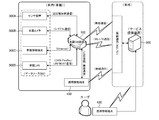
- FIG. 1 is a network configuration diagram inside and outside a vehicle to which an in-vehicle gateway device 100 (hereinafter referred to as an in-vehicle GW device) of the first embodiment is applied.
- the in-vehicle GW apparatus 100 is an in-vehicle device that is directly connected to the in-vehicle data source 300 or connected to an in-vehicle network to which the data source 300 is connected.
- a vehicle will be described as an example, but the present invention can also be applied to other moving objects (such as trains, robots or flying objects operated automatically or wirelessly).
- the in-vehicle GW apparatus 100 can be connected to a network outside the vehicle, and is configured as a network node that relays between the inside and outside the vehicle.
- the in-vehicle GW apparatus 100 includes communication interfaces for wireless communication conforming to a wireless LAN standard such as Wi-Fi via an access point, and mobile phone communication such as 3G and LTE (Long Term Evolution) relaying a base station. Yes.
- the in-vehicle GW apparatus 100 can be connected to an external network outside the vehicle through a plurality of communication paths (external communication methods).
- the outside-vehicle network is, for example, an IP (Internet Protocol) network.
- the in-vehicle GW apparatus 100 can be connected to the service providing apparatus 500 via the IP network.
- the in-vehicle GW apparatus 100 can upload various data acquired from the in-vehicle data source 300 to the service providing apparatus 500 and receive various data from the service providing apparatus 500.
- the in-vehicle GW apparatus 100 can also be connected to a network outside the vehicle via a portable information terminal 400 provided with a Wi-Fi or 3G / LTE communication interface.
- the in-vehicle GW apparatus 100 can be connected to the portable information terminal 400 by USB or by short-range communication based on a standard such as wireless communication or Bluetooth (registered trademark) / NFC.
- the portable information terminal 400 is a mobile device having a communication function such as a multi-function mobile phone such as a smartphone, a mobile phone, and a tablet terminal. Further, the user can directly connect to the service providing apparatus 500 from the portable information terminal 400 or a computer apparatus having other communication functions regardless of the in-vehicle GW apparatus 100.
- the in-vehicle GW apparatus 100 can be connected to the in-vehicle data source 300 directly or via an existing in-vehicle network.
- the data source 300 includes, for example, a microphone (sound collecting device), a sensor device 300A such as a human sensor or a vital sensor worn by a user, a drive recorder equipped with a camera (photographing device), an in-vehicle camera for photographing the inside of the vehicle, and the like.
- There are an in-vehicle information terminal 300C such as a navigation system provided with display means such as an in-vehicle camera 300B and a liquid crystal display device, an in-vehicle LAN 300D, and the like.
- a vehicle control system vehicle ECU, a multimedia system audio device, and the like are data sources.
- the in-vehicle GW apparatus 100 performs data communication using a different communication method for each data source 300 according to the communication method provided in each data source 300 or in-vehicle network.
- the sensor device 300A performs data communication by short-range wireless communication.
- the in-vehicle camera 300B performs data communication by serial (UART) communication (RS232C, RS422, RS485) connected to the in-vehicle GW apparatus 100 with a cable.
- the in-vehicle information terminal 300C performs data communication by Ethernet communication connected by a LAN cable.
- the in-vehicle camera 300B can include an interface board including, for example, a UART circuit and a MIDI terminal.
- the in-vehicle camera 300B can output and display the captured video on the in-vehicle information terminal 300C and other displays via the MIDI terminal.
- the in-vehicle LAN 300D has an in-vehicle network built in a communication system such as CAN (controller area network), FlexRay, LIN, and MOST (media oriented systems transport).
- the in-vehicle GW apparatus 100 is connected to each of one or a plurality of in-vehicle networks constituting the in-vehicle LAN 300D, and performs data communication by each communication method.
- FIG. 2 is a diagram illustrating a configuration block of the in-vehicle GW apparatus 100.
- the in-vehicle GW apparatus 100 has, as a hardware configuration, a control that controls the communication device 110 that forms a communication interface with each data source 300 (including the in-vehicle LAN 300D) and the portable information terminal 400, and the entire in-vehicle GW apparatus 100.
- Device 120 includes the in-vehicle GW apparatus 100.
- the communication device 110 includes an in-vehicle communication (internal communication) interface 111 such as Ethernet, CAN, UART, USB, and short-range wireless communication, and an out-of-vehicle communication (external communication) interface 112 such as wireless communication and mobile phone communication.
- an in-vehicle communication (internal communication) interface 111 such as Ethernet, CAN, UART, USB, and short-range wireless communication
- an out-of-vehicle communication (external communication) interface 112 such as wireless communication and mobile phone communication.
- the in-vehicle communication interface can be configured to include a wireless communication function with the portable information terminal 400 for connection to an external network via the portable information terminal 400.
- the control device 120 is configured to include each functional unit that mainly operates by software.
- the control device 120 can control each data source 300. For example, sensor control (operation and data detection) of the sensor device 300A, imaging control (including video output control) of the in-vehicle camera, and terminal control of the in-vehicle information terminal 300C can be performed.
- control device 120 can output the data received from the external network to the data source 300, or control the data source 300 based on the received data.
- one or both of the data sources 300 can be controlled between the data sources 300. For example, it is possible to perform control for displaying detection data acquired by the sensor device 300A and video captured by the in-vehicle camera 300B on the display of the in-vehicle information terminal 300C.
- the control device 120 of this embodiment includes an in-vehicle communication control unit 121, an out-of-vehicle communication control unit 122, and a gateway control unit (GW control unit) 123.
- GW control unit gateway control unit
- the in-vehicle GW apparatus 100 is installed with respective device drivers such as wireless communication, mobile phone communication, UART, USB, and short-range wireless communication.
- the in-vehicle communication control unit 121 and the out-of-vehicle communication control unit 122 perform communication control via the in-vehicle communication interface 111 and the out-of-vehicle communication interface 112 through each device driver.
- the in-vehicle communication control unit 121 can also control communication with, for example, the in-vehicle LAN 300D without using a device driver.
- the out-of-vehicle communication control unit 122 can perform access point registration processing for wireless communication such as Wi-Fi.
- the out-of-vehicle communication control unit 122 can detect and register access points at various locations as the vehicle physically moves.
- the GW control unit 123 includes a network control unit 123A, a communication control unit 123B, and a storage unit 123C.
- the network control unit 123A includes a routing control unit 1231, a protocol conversion unit 1232, and a security unit 1233.
- the routing control unit 1231 performs routing control when transmitting data collected from each data source 300 (including the in-vehicle LAN 300D) to the outside network, and transmits data received from the outside network to each data source 300. Perform routing control. In addition, routing control in data communication between the data sources 300 in the in-vehicle network is also performed.
- the protocol conversion unit 1232 performs a protocol conversion process between different communication methods corresponding to each data source.
- a communication method for each data source 300 can be stored in advance as a protocol conversion table. For example, protocol conversion is performed when data received from an external network is transmitted to the data source 300.
- the security unit 1233 performs communication setting and communication processing of SSL (Secure Sockets Layer) / TLS (Transport Layer Layer Security) protocol. SSL / TLS communication can be set for each data source 300. When data is transmitted from the in-vehicle network to the external network, the security unit 1233 checks whether SSL / TLS is set and performs encryption processing. It can be carried out.
- SSL Secure Sockets Layer
- TLS Transport Layer Layer Security
- the storage unit 123C stores various data processed by the control device 120, information used for each process, data and information received from a network outside the vehicle, and the like.
- the storage unit 123 ⁇ / b> C is built in the in-vehicle GW device 100, but the storage unit 123 ⁇ / b> C may be externally attached to the in-vehicle GW device 100, for example.
- the in-vehicle GW apparatus 100 can include a connection port (such as a USB port) for connecting to the external storage unit 123C.
- the communication control unit 123B includes a communication state monitoring unit 1234, a communication path selection unit 1235, a monitoring control unit 1236, and a Config setting control unit 1237. Based on the Config setting information, the communication control unit 123B performs communication route selection control, data monitoring control, and data transmission control for transmitting data collected from the data source 300 to the external network.
- 3 to 6 are diagrams illustrating an example of Config setting information according to the present embodiment.
- FIG. 3 is a diagram showing an example of the communication connection config setting information, which is used for communication path selection control of the communication path selection unit 1235.
- the communication connection config setting includes a communication path setting at the time of data transmission from the in-vehicle network to the outside network and a communication path setting at the time of data reception from the outside network to the in-vehicle network.
- the in-vehicle GW apparatus 100 of this embodiment is mounted on a moving body such as a vehicle. For this reason, for example, the in-vehicle GW apparatus 100 is assigned a dynamic IP address as a network node. The in-vehicle GW apparatus 100 actively connects to and establishes a connection with the service providing apparatus 500 of the outside-vehicle network when transmitting and receiving data.
- the communication connection for data reception from the outside-vehicle network mainly includes a communication path for configuration setting and a communication path for large-scale data distribution.
- the Config setting information can be received from the service providing apparatus 500 as described later.
- the large-scale data distribution is, for example, map data used for the in-vehicle information terminal 300C.
- the communication connection settings include automatic setting and / or priority setting.
- the in-vehicle GW apparatus 100 can be connected to a network outside the vehicle via a plurality of communication scheme paths. For example, one of the three routes of Wi-Fi, via a portable information terminal, and 3G / LTE can be selected, and priority can be set for the three routes. Also, the priority of “automatic” can be arbitrarily determined in advance, for example, Wi-fi> via mobile information terminal> 3G / LTE.
- the communication connection during data transmission from the in-vehicle network to the outside network includes, for example, a vital information upload communication path, a vehicle information upload communication path, and a log information upload communication path.
- photographed with the vehicle-mounted camera 300B can also be included.
- automatic setting and / or priority setting can be performed.
- the communication connection config setting includes a setting for enabling / disabling each of a plurality of communication paths used by the in-vehicle GW apparatus 100.
- Wi-Fi communication use settings, 3G / LTE communication use settings, and portable information terminal communication use settings can be set to valid (ON) / invalid (OFF).
- priority can be given to valid / invalid of the communication use setting, and control can be performed so as not to select the communication path set to invalid.
- the communication connection config setting includes URL designation (registration) of the service providing apparatus 500 that is a connection destination of the outside-vehicle network.
- URL designation registration
- the in-vehicle GW apparatus 100 is connected to a plurality of service providing apparatuses 500, a plurality of URLs are designated.
- each data node 300 may be connected to a different service providing apparatus 500. That is, it is possible to associate the service providing device 500 to be connected for each data source and control the specific service providing device 500 to transmit the data acquired from the specific data source.
- FIG. 4 is a diagram showing an example of in-vehicle LANConfig setting information.
- the in-vehicle LANConfig setting information is used for monitoring control by the monitoring control unit 1236.
- the in-vehicle LAN 300D can output vehicle information monitored by the vehicle ECU to the in-vehicle GW apparatus 100.
- the in-vehicle LANConfig setting information includes setting information such as a vehicle information transfer (upload) cycle, an average vehicle speed threshold, and a driving time threshold. Moreover, ON / OFF setting information for selecting vehicle information to be transmitted to the service providing apparatus 500 is also included. For example, transmission ON / OFF of vehicle information such as vehicle speed, engine speed, water temperature, fuel consumption, travel distance, and select lever position can be set.
- FIG. 5 is a diagram illustrating an example of the sensor device Config setting information.
- the sensor device Config setting information is used for monitoring control by the monitoring control unit 1236.
- the sensor device 300A can measure or / and calculate a user's heart rate, pulse interval, blood pressure, and the like and output the measured value to the in-vehicle GW apparatus 100.
- the sensor device Config setting information includes setting information such as a vital information transfer (upload) cycle, a heart rate transfer threshold, and a heart rate abnormality threshold.
- ON / OFF setting information for selecting vital information to be transmitted to the service providing apparatus 500 is also included. For example, transmission ON / OFF of each vital information such as heart rate, pulse interval, pulse wave propagation time, amplitude value can be set.
- FIG. 6 is a diagram illustrating an example of the log config setting information.
- the GW control unit 123 can collect a log indicating normality / abnormality of each process of the entire control device 120. Each unit included in the GW control unit 123 generates a log for each process and stores the log in the storage area. Log Config setting information sets the timing for data transmission of the accumulated log information to the service providing apparatus 500.
- the Config setting control unit 1237 sets (updates) the Config setting information input to the control device 120 in a predetermined storage area so that the communication path selection unit 1235 and the monitoring control unit 1236 can use them.
- the Config setting information can be set via the in-vehicle information terminal 300C.
- the Config setting control unit 1237 can display, for example, a Config setting input screen on the display of the in-vehicle information terminal 300 ⁇ / b> C, and can store the Config setting information input by the user from the input screen.
- the Config setting control unit 1237 uploads the set (updated) Config setting information to the service providing apparatus 500 at a predetermined timing and a predetermined communication path. To do.
- the Config setting information can be set by the service providing apparatus 500.
- the user can connect to the service providing apparatus 500 from the portable information terminal 400, and the service providing apparatus 500 can provide the same Config setting function as the Config setting control unit 1237.
- the service providing apparatus 500 can display the Config setting input screen on the display of the portable information terminal 400, and can store the Config setting information input by the user from the input screen in a storage area in the service providing apparatus 500. Then, the service providing apparatus 500 transmits the set Config setting information based on the Config acquisition request from the in-vehicle GW apparatus 100.
- the Config setting control unit 1237 updates the Config setting information received from the service providing apparatus 500.
- FIG. 7 is a flowchart showing an update registration process for Config setting information.
- the user can connect to the service providing apparatus 500 from the portable information terminal 400 and register (update) the Config setting information for each user through the Config setting function provided by the service providing apparatus 500 (S501, S601). That is, the Config setting information can be updated and registered on the outside-vehicle network side.
- the in-vehicle GW apparatus 100 can be activated by receiving power supply from a vehicle battery or the like in conjunction with ON / OFF of an ignition switch of the vehicle, for example (S101).
- the in-vehicle GW apparatus 100 can connect to the service providing apparatus 500 at the time of activation and acquire the Config setting information that is directly updated / registered in the service providing apparatus 500.
- the in-vehicle GW apparatus 100 performs a communication route selection process based on the communication connection config setting information illustrated in FIG. 3 (S102).
- the in-vehicle GW apparatus 100 (Config setting control unit 1237) transmits a Config setting information acquisition request to the service providing apparatus 500 through the selected communication path (S103).
- the service providing apparatus 500 transmits Config setting information in response to the request (S502).
- the in-vehicle GW apparatus 100 updates the received Config setting information (S104).
- the in-vehicle information terminal 300C can provide the Config setting function.
- the in-vehicle information terminal 300C outputs the Config setting information input by the user to the in-vehicle GW apparatus 100 (S301).
- the in-vehicle GW apparatus 100 updates the input Config setting information (S105).
- the Config setting information is updated and registered on the in-vehicle information terminal 300C side, that is, the in-vehicle network side
- the in-vehicle GW apparatus 100 performs a communication route selection process based on the communication connection Config setting information (S106), and a predetermined timing.
- the Config setting information is uploaded to the service providing apparatus 500 (S107).
- the service providing apparatus 500 updates and registers the Config setting information uploaded from the in-vehicle GW apparatus 100 for each user (S503).
- data communication between the in-vehicle GW apparatus 100 and the service providing apparatus 500 is performed using both a user identification ID and a solid identifier (for example, a MAC address) of the vehicle GW apparatus 100 that are set in advance. It can be carried out.
- the in-vehicle GW apparatus 100 controls the uploaded data to include a solid identifier.
- FIG. 8 is a flowchart showing communication path connection processing.
- the in-vehicle GW apparatus 100 acquires the communication connection Config setting information illustrated in FIG. 3 after activation (S110).
- the in-vehicle GW apparatus 100 performs a communication connection process for a communication path whose connection flag is ON (S111).
- the connection flag is valid (ON) / invalid (OFF) in the communication use setting of each communication method.
- control when there are a plurality of communication paths whose connection flag is ON, control is performed so as to maintain the communication connections of all the plurality of communication paths.
- control is performed so as to maintain the constantly connected state for all the plurality of communication paths whose connection flags are ON.
- an appropriate communication path is selected based on the Config setting according to the communication state of each communication path, and data communication is performed with the network outside the vehicle.
- the communication status monitoring unit 1234 monitors the communication status (connected / blocked) of the communication path whose connection flag is ON (S112).
- the communication state monitoring unit 1234 outputs the communication state of each communication path to the communication control unit 123B.
- the communication state monitoring unit 1234 checks whether or not there is a connection state monitoring end signal (for example, an ignition switch OFF signal of the vehicle) (S113). If the monitoring is not terminated, the process proceeds to step S114, and the communication control unit 123B continues to monitor the communication state when it is determined that the communication path whose connection flag is ON is not blocked (NO in S114).
- step S114 when it is determined that the communication is blocked (YES in S114), the process returns to step S111, and the communication control unit 123B performs the communication connection process again on the communication path that is blocked when the connection flag is ON.
- step S115 if there is an input of a connection state monitoring end signal in step S113 and the monitoring is to be ended, the process proceeds to step S115, where all connected communication paths are blocked.
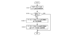
- FIG. 9 is a flowchart showing monitoring control for each data source.
- the communication control unit 123B acquires the Config setting information of each data source 300 (S131).
- the communication state monitoring for example, the presence or absence of a signal for ending the monitoring control of the data source such as an OFF signal of an ignition switch of the vehicle is confirmed (S132).
- the monitoring control is performed based on the Config setting information set for each data source 300.
- the data source 300 can output time-sequential data to the in-vehicle GW apparatus 100.
- the monitoring control based on the Config setting information monitors the data collected from the data source 300.
- the abnormality detection control (S133) detects an abnormality when data exceeding a threshold is detected, and the data source 300 Data collection / transmission control (S134) for transmitting the collected data to the outside-vehicle network is included.
- the monitoring control unit 1236 detects an abnormality for each data source for the data output from the data source 300, and when an abnormality is detected, for example, displays on the in-vehicle information terminal 300C that the abnormality has been detected. Notification processing can be performed.
- FIG. 10 and 11 are diagrams showing an example of the abnormality monitoring control.
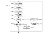
- FIG. 10 is a flowchart showing a process flow of abnormality monitoring control based on the in-vehicle LANConfig setting information.
- the monitoring controller 1236 acquires vehicle information from the in-vehicle LAN 300D (vehicle ECU or the like) (S133A).
- the monitoring control unit 1236 calculates the average vehicle speed at the set operation time interval (S133B).
- the monitoring control unit 1236 performs a determination process for determining whether or not the calculated average vehicle speed exceeds the average vehicle speed threshold set in the in-vehicle LANConfig setting information (S133C).
- the abnormality notification flag is ON (NO in S133E)
- the abnormality notification flag is updated to OFF (S133H).
- step S133D if it is determined in step S133D that the calculated average vehicle speed exceeds the average vehicle speed threshold as a result of the determination process (NO in S133D), the abnormality notification flag is updated to ON (S133F). Based on the fact that the abnormality notification flag is ON, the monitoring control unit 1236 performs notification processing to the in-vehicle information terminal 300C (S133G).
- FIG. 11 is a flowchart showing a monitoring control process flow based on the sensor device config setting information.
- the monitoring control unit 1236 acquires vital information from the sensor device 300A (a vital sensor such as a heart rate monitor or a pulse meter) (S1331).
- the monitoring control unit 1236 calculates a heart rate from the acquired vital information (S1332), and stores the calculated heart rate (S1333).
- the monitoring control unit 1236 performs a determination process for determining whether or not the calculated heart rate exceeds the heart rate abnormality threshold value set in the sensor device Config setting information (S1334).
- the abnormality notification flag is OFF (S1336). If the abnormality notification flag is ON (NO in S1336), the abnormality notification flag is updated to OFF (S1339).
- step S1335 if it is determined in step S1335 that the calculated heart rate exceeds the heart rate abnormality threshold value as a result of the determination process (NO in S1335), the abnormality notification flag is updated to ON (S1337).
- the monitoring control unit 1236 performs notification processing to the in-vehicle information terminal 300C based on the fact that the abnormality notification flag is ON (S1338).
- FIG. 12 is a flowchart showing data collection / transmission control of the monitoring control unit 1236.
- Data collection / transmission control includes data transmission control, communication path selection, and data retention processing when communication is interrupted.
- Data transmission control performs filtering control of data to be transmitted to the outside network and data transmission timing control based on the Config setting information.
- the monitoring control unit 1236 acquires data from each data source 300 (S1341), and performs transmission permission / inhibition determination processing of the collected data based on the Config setting information (S1342).
- a threshold value can be set and only data exceeding the threshold value can be transmitted.
- the monitoring control unit 1236 determines whether or not the data is transmission target data based on the Config setting information (S1343). If the collected data is transmission target data, the corresponding data is transmitted to the outside network. (YES in S1343). On the other hand, if the collected data is not transmission target data, control is performed so that the data is not transmitted to the network outside the vehicle (NO in S1343).
- the timing of data transmission can also be controlled. For example, when the data source 300 outputs data at a short time interval, if all the data is transmitted to the outside-vehicle network, the communication amount increases. Therefore, a data transfer interval longer than the data output time interval of the data source is set based on the Config setting information.
- the monitoring control unit 1236 determines the transmission timing of the data determined as the transmission target data in step S1343 based on the Config setting information (S1344). If the current timing is the transmission timing (transfer cycle) set (YES in S1344), the monitoring control unit 1236 controls the transmission target data to be transmitted to the network outside the vehicle, and if it is not the transmission timing (NO in S1344). The transmission target data is controlled not to be transmitted to the outside network.
- filtering control and data transmission timing control can be performed so that data in which an abnormality is detected by the abnormality detection control is always transmitted to the outside-vehicle network. Further, although filtering control and data transmission timing control are linked as described above, any one of the controls can be applied.
- the communication route selection unit 1235 performs processing for selecting a communication route to the outside network in the data collection / transmission control by the monitoring control unit 1236.
- the communication path selection unit 1235 confirms the communication state based on the communication path monitoring by the communication state monitoring unit 1234 (S1345), and is designated for each data source 300 of data to be transmitted from the communication connection config setting information or Based on the priority order, the currently connected communication path is selected (S1346).
- the monitoring control unit 1236 transmits data collected based on the Config setting information via the out-of-vehicle communication control unit 122 (service provision). (S1348).
- the communication path selection unit 1235 cannot select the currently connected communication path when all the communication paths set in the communication connection config setting information are in the blocked state. Therefore, when the designated or priority communication path cannot be selected (NO in S1347), the monitoring control unit 1236 performs data holding processing when communication is interrupted assuming that data transmission to the outside-vehicle network cannot be performed ( S1349).
- the data holding process at the time of communication interruption is a process of temporarily storing data collected by the monitoring control unit 1236 in time series until a communication path becomes available.
- the monitoring control unit 1236 may transmit the temporarily held data together with the data collected this time to the network outside the vehicle without performing the data transmission at the previous data transmission timing. it can.
- Wi-Fi cannot be used at the data transmission timing and 3G / LTE can be used
- the data is temporarily stored without being transmitted, and when Wi-Fi becomes available, Data can be transmitted to the network outside the vehicle.
- video captured by the in-vehicle camera 300B is transmitted to a network outside the vehicle, since the data capacity is large, video data is temporarily stored until the environment where Wi-Fi can be used.
- -Can transmit in bulk when Fi is available.
- the video data of the in-vehicle camera 300B is a communication path only for Wi-Fi
- the vehicle information of the in-vehicle LAN 300D is Wi-Fi or 3G / LTE.
- Communication paths, and abnormality information detected by abnormality monitoring control can be set as all communication paths (either Wi-Fi, 3G / LTE, or via a portable information terminal).
- the abnormality monitoring control and data collection / transmission control of this embodiment are executed independently. That is, even when various data collected from the data source 300 cannot be transmitted to the outside network due to communication interruption, the abnormality status detected by the abnormality monitoring control is notified to the user via the in-vehicle information terminal 300C. Can do. For this reason, the abnormal status can be notified to the user regardless of the communication state with the network outside the vehicle.
- the service providing apparatus 500 can provide vehicle information and vital information received from the in-vehicle GW apparatus 100 as vehicle operation information and user health management information. For example, when the user connects to the service providing apparatus 500 from the portable information terminal 400, the user can view each monitoring result (monitoring screen) based on the vehicle information and vital information received from the in-vehicle GW apparatus 100.
- the service providing apparatus 500 can provide information to the in-vehicle GW apparatus 100 with respect to the monitoring result of the vehicle information and vital information received from the in-vehicle GW apparatus 100.
- the service providing apparatus 500 performs abnormality detection by setting a threshold different from the abnormality detection control of the monitoring control unit 1236, or a plurality of vehicle information received in addition to the average vehicle speed (engine speed, water temperature, fuel consumption,
- the detection result can be fed back to the in-vehicle GW apparatus 100 by performing complex abnormality detection from the travel distance, the select lever position, and the like.
- the abnormality detection control of the in-vehicle GW apparatus 100 is performed independently of the abnormality detection control of the service providing apparatus 500.
- the abnormality detection control of the service providing apparatus 500 is because vehicle information, vital information, and the like cannot be acquired from the in-vehicle GW apparatus 100 in a state where communication is interrupted.
- the abnormality detection control by the monitoring control unit 1236 is continuously performed even when communication is interrupted.
- the in-vehicle GW apparatus 100 can acquire user's voice information from a sound collection microphone as a data source.
- the in-vehicle GW apparatus 100 transmits voice information to the service providing apparatus 500.
- the service providing apparatus 500 has a voice recognition function and can convert received voice information into text. Utilizing this voice recognition function, for example, when the service providing apparatus 500 recognizes that the user has uttered “hot”, the service providing apparatus 500 generates an air conditioner control signal for lowering the air conditioning temperature of the in-vehicle air conditioner by a predetermined temperature, and the vehicle GW Can be transmitted to the device 100.
- the vehicle GW apparatus 100 can send the received air conditioner control signal to the in-vehicle LAN 300D so that the vehicle ECU can control to lower the air conditioning temperature of the in-vehicle air conditioner.
- FIG. 13 is a diagram illustrating an example of the communication connection config setting information of the environment sensor.
- the environmental sensor is the above-described sensor device 300A.
- Examples of the environmental sensor include a temperature sensor, a humidity sensor, an atmospheric pressure sensor, an impact (acceleration), and an illuminance sensor.
- route at the time of the data transmission from an in-vehicle network to an external network is set similarly to the example of FIG. Note that, in the example of FIG. 13, communication connection Config setting information common to a plurality of sensors as one environmental sensor is defined, but can be individually defined for each sensor.
- FIG. 14 is a diagram illustrating an example of the environment sensor config setting information.
- each environmental sensor such as a temperature sensor, a humidity sensor, an atmospheric pressure sensor, an impact (acceleration), and an illuminance sensor is used as a data source.
- Control abnormality detection control and data collection / transmission control
- a common transfer cycle is defined as a plurality of sensors as one environmental sensor, but can be defined individually for each sensor.
- FIG. 15 is a flowchart showing a process flow of the abnormality monitoring control based on the environmental sensor config setting information.
- the monitoring control unit 1236 acquires sensor information from each environmental sensor (S133a).
- the monitoring control unit 1236 stores the acquired sensor information (S133b), and performs a determination process for determining whether or not the corresponding threshold is exceeded for each sensor set in the environmental sensor config setting information (S133c). .
- the determination process if the collected sensor information does not exceed the threshold (YES in S1335), it is confirmed whether or not the abnormality notification flag is OFF (S1336). If the abnormality notification flag is ON (NO in S1336), the abnormality notification flag is updated to OFF (S1339).
- step S1335 if it is determined in step S1335 that the sensor information exceeds the threshold as a result of the determination process (NO in S1335), the abnormality notification flag is updated to ON (S1337).
- the monitoring control unit 1236 performs notification processing to the in-vehicle information terminal 300C based on the fact that the abnormality notification flag is ON (S1338).
- FIG. 16 is a diagram illustrating an example of the in-vehicle camera Config setting information.
- the in-vehicle camera 300B can be configured to include one or a plurality of cameras such as an in-vehicle shooting camera and an out-of-vehicle shooting camera, for example.
- the monitoring control (abnormality detection control and data collection / transmission control) described in FIGS. 9 to 11 using the in-vehicle camera 300B as a data source can be performed. it can. In the example of FIG. 16, a plurality of different monitoring controls are performed from one data source and a common transfer cycle is defined, but can be set individually.
- FIG. 17 is a flowchart showing a process flow of abnormality monitoring control based on the in-vehicle camera Config setting information.
- the monitoring control unit 1236 acquires shooting information from the in-vehicle camera 300B (S133d).
- the monitoring control unit 1236 performs image processing such as calculating whether the abnormality detection target defined for each monitoring control is reflected in the photographing information, or calculating a distance from the person or object in the imaging information, and performs abnormality determination processing. This is performed (S133e). If no abnormality is detected as a result of the determination process (YES in S1335), it is confirmed whether or not the abnormality notification flag is OFF (S1336). If the abnormality notification flag is ON (NO in S1336), the abnormality notification flag is updated to OFF (S1339).
- the abnormality notification flag is updated to ON (S1337).
- the monitoring control unit 1236 performs notification processing to the in-vehicle information terminal 300C based on the fact that the abnormality notification flag is ON (S1338).
- the in-vehicle GW apparatus 100 of the present embodiment selects a communication path for each data source 300 from a plurality of external communication methods, and based on a priority setting in which a plurality of external communication methods are arranged in a predetermined priority order.
- the communication path is switched for each data source 300 according to each communication connection state of a plurality of external communication methods. At this time, switching the communication path includes not being connected to the network outside the vehicle through a communication path other than the predetermined communication path.
- the data output from the data source 300 is monitored, and the data is transmitted to the network outside the vehicle through the communication path selected according to the data source 300.
- the data source 300 in a moving body such as a vehicle is stably connected to a network outside the moving body, and an appropriate communication path corresponding to the data source 300 in the moving body is selected to be outside the moving body. Can be connected to other networks.
- the in-vehicle GW apparatus 100 performs abnormality detection control independently of uploading data to the outside network and detects data that satisfies the monitoring rule. And when the data which satisfy
- FIG. 18 is a network configuration diagram inside and outside the vehicle to which the in-vehicle gateway device 100 (hereinafter referred to as an in-vehicle GW device) of the second embodiment is applied.
- the in-vehicle GW apparatus 100 is the same as that in the first embodiment.
- the in-vehicle GW apparatus 100 according to the present embodiment is other than the other mobile bodies (regardless of unmanned manned persons, other mobile bodies equipped with communication devices, other mobile bodies equipped with the in-vehicle GW apparatus 100A, etc.)
- Other external connection devices 600 can be connected via a network outside the vehicle.
- the vehicle-mounted GW apparatus 100 can be mounted on each of a plurality of moving bodies, and cooperation between the moving bodies can be achieved. As shown in FIG. 18, the first moving body on which the in-vehicle GW device 100 is mounted and the second moving body on which the on-vehicle GW device 100A is mounted can communicate with each other and cooperate with each other by wireless communication. it can.
- the vehicle-mounted camera Config setting information shown in FIG. 16 will be described as an example.
- the first moving body and the second moving body are moving in relation to each other.
- the obstacle detection information is directly transmitted to the second moving body by wireless communication, and the second It can be configured to notify the mobile body in real time.
- the setting information of both mobile bodies (such as the MAC address of the in-vehicle GW apparatus 100A) is set in the communication connection config setting information shown in FIG. 3, and the in-vehicle camera config setting information shown in FIG.
- a process of transmitting detection information to another registered in-vehicle GW apparatus 100 is set.
- an output device such as a display device or a speaker of the in-vehicle information terminal 300C of the first moving body is used as shown in FIG.
- the notification process for notifying the user can also be performed.
- the supervisory control unit 1236 can perform an assist process so that the mobile body performs control associated with abnormality detection.
- the in-vehicle GW apparatus 100 can perform notification processing related to vehicle control and output processing of control signals related to vehicle control to a vehicle ECU (vehicle control device) that controls the moving body through the in-vehicle LAN 300D.
- vehicle ECU vehicle control device
- the vehicle ECU performs vehicle control such as travel stop, deceleration, and automatic steering avoidance operation based on the notification output from the monitoring control unit 1236, or the vehicle ECU performs travel stop or deceleration based on the control signal output from the monitoring control unit 1236.
- Vehicle control such as deceleration and automatic steering avoidance operation can be performed.
- the in-vehicle GW apparatus 100 when an obstacle is detected in the first moving body, the in-vehicle GW apparatus 100 outputs a notification and a control signal related to the stop operation, deceleration, and automatic steering operation of the steering wheel to the vehicle ECU, Control of the first moving body can be assisted.
- the in-vehicle GW device 100A mounted on the second moving body in synchronization with the vehicle control of the first moving body or independently based on the notification received from the first moving body. It is possible to assist the control such as the traveling stop and deceleration of the movable body 2 and the steering wheel automatic avoiding operation.
- the monitoring rule used for the abnormality detection control of the present embodiment is set in advance in, for example, the in-vehicle camera Config setting information, and the traveling stop or deceleration used for assist processing with respect to the monitoring rule, automatic steering avoidance operation Such notifications and control signals relating to vehicle control are associated in advance.
- the in-vehicle GW apparatus 100 can be connected to the external connection device 600 by wireless communication.
- the external connection device 600 is, for example, a portable terminal device (Ex, tablet computer) that can be carried. Further, as the external connection device 600, for example, a removable in-vehicle information terminal 300C having a wireless communication function may be used.
- the monitoring control unit 1236 can perform notification processing (including audio output from a speaker) for transmitting the above-described obstacle detection information and the like to the external connection device 600.
- the notification process to the external device 600 can be performed in synchronization with or independently of the assist process described above.
- FIG. 19 is a flowchart illustrating a processing flow of monitoring control and abnormality monitoring control for each data source according to the second embodiment.
- the example of FIG. 19 shows the processing flow of the abnormality monitoring control based on the in-vehicle camera Config setting information.
- the communication control unit 123B acquires the Config setting information of each data source 300 (S131). If there is no signal for ending the monitoring control of the data source (NO in S132), the monitoring control based on the Config setting information set for each data source 300 is performed (S133).
- the monitoring control unit 1236 acquires shooting information from the in-vehicle camera 300B (S133-1).
- the monitoring control unit 1236 performs image processing such as calculating whether the abnormality detection target defined for each monitoring control is reflected in the photographing information, or calculating a distance from the person or object in the imaging information, and performs abnormality determination processing. Perform (S133-2).
- the sound information input to the in-vehicle microphone (sound collecting device) connected to the in-vehicle GW apparatus 100 is collected, and the emergency information is obtained from, for example, the voice or volume of the user riding in the vehicle. It is also possible to determine the level of degree and risk.
- the in-vehicle GW apparatus 100 can transmit voice information to the service providing apparatus 500 (server having a voice recognition function) outside the vehicle, and can receive a voice recognition result from the service providing apparatus 500.
- the service providing apparatus 500 server having a voice recognition function
- the abnormality notification flag is OFF (S133-4). If the abnormality notification flag is ON (NO in S133-4), the abnormality notification flag is updated to OFF (S133-5). On the other hand, if an abnormality is detected as a result of the determination process in step S133-3 (NO in S133-3), the abnormality notification flag is updated to ON (S133-7).
- the monitoring control unit 1236 performs in-vehicle notification processing based on the fact that the abnormality notification flag is ON (S133-8).
- the notification process in step S133-8 includes a notification process to the in-vehicle information terminal 300C in the vehicle of the first embodiment and a notification process to the vehicle control system.
- the notification process to the vehicle control system includes the monitoring process described above. This is assist processing by the control unit 1236.
- the assist process includes the travel stop and deceleration of the moving body, and the automatic avoidance operation of the steering wheel.
- the urgency level and the risk level based on the sound information are set. Can be reflected. For example, when the level of urgency is “high”, traveling can be stopped by sudden braking. If the level of urgency is “low”, it can be controlled to stop traveling with a braking force smaller than that of sudden braking. At this time, when the voice of the user is higher than a predetermined value, or when the user's utterance includes a highly urgent word such as “Dangerous!”, The urgency level should be set to “high”. Can do.
- the in-vehicle GW apparatus 100 refers to the Config setting information (for example, the in-vehicle camera Config setting information), and the other in-vehicle GW apparatus 100A outside the vehicle specified in the Config setting information, the external connection device 600.
- notification processing based on the fact that the abnormality notification flag is ON is performed on the service providing apparatus 500 (S133-9).
- step S134 as in the first embodiment, data collection / transmission control for transmitting data collected from the data source 300 to the network outside the vehicle is performed.
- step S133-9 the abnormality notification flag is ON.
- direct exchange is performed with the in-vehicle GW apparatus 100A other than the service providing apparatus 500 and the external connection device 600 to achieve external cooperation. be able to.
- communication connection Config setting including priority setting in which a plurality of external communication methods are arranged in a predetermined priority order. Information is defined.
- the in-vehicle GW apparatus 100 (communication path selection unit 1235) switches the communication path for each data source according to each communication connection state of the plurality of external communication methods based on the communication connection config setting information, It can be connected to the in-vehicle GW apparatus 100A and the external connection device 600.
- the monitoring control unit 1236 performs an assist process for assisting the control of the moving body in accordance with the abnormality determination result together with the abnormality determination process, and stops the traveling of the moving body for the determined abnormality. It is possible to automatically perform control such as deceleration, steering wheel automatic avoidance operation, and the like.
- the first moving body is an unmanned vehicle (automatically operated vehicle)
- the second moving body is a manned vehicle
- the first moving body and the second moving body are together.
- the in-vehicle GW apparatus 100 detects an obstacle (for example, a person) on the unmanned vehicle side
- the unmanned vehicle is connected to the external connection device 600 held by the manned vehicle or the user operating the manned vehicle.
- vehicle control such as running stop and deceleration can be automatically performed. By comprising in this way, the accident of an unmanned vehicle can be prevented.
- the external connection device 600 can receive an input of a moving body control instruction for the notified abnormality, and can transmit the received control instruction to the in-vehicle GW apparatus 100 of the unmanned vehicle. That is, the unmanned vehicle can be remotely operated from the external connection device 600 via the in-vehicle GW apparatus 100.
- notification processing may be performed on one or a plurality of vehicles within a predetermined distance range of a vehicle in which an abnormality has been detected, and each surrounding vehicle may perform assist processing.
- the vehicle that caused the accident notifies the vehicle in the vicinity of the accident site or the vehicle approaching the accident site of the occurrence of the accident, so that the user can automatically stop or slow down the vehicle by himself or by assist processing. And avoidance operations can be performed. It is possible to prevent secondary disasters accompanying accidents and prevent accidents from expanding.
- the in-vehicle gateway device 100 can be configured as an in-vehicle gateway system.
- the communication device 110 and the control device 120 can be configured as individual devices, and can be configured as an in-vehicle gateway system in which these are connected to each other.
- each functional unit of the control device 120 can be appropriately configured as an individual processing device and configured as an in-vehicle gateway system.
- Each function of the control device 120 can be realized by a program, a computer program prepared in advance for realizing each function is stored in the auxiliary storage device, and a control unit such as a CPU is stored in the auxiliary storage device.
- the function of each unit can be operated by reading the program stored in the main storage device and executing the program read in the main storage device by the control unit.
- Computer-readable recording media include optical disks such as CD-ROMs, phase change optical disks such as DVD-ROMs, magneto-optical disks such as MO (Magnet-Optical) and MD (Mini-Disk), floppy (registered trademark) disks, Examples include magnetic disks such as removable hard disks, memory cards such as compact flash (registered trademark), smart media, SD memory cards, and memory sticks.
- a hardware device such as an integrated circuit (IC chip or the like) specially designed and configured for the purpose of the present invention is also included as a recording medium.
- a program for realizing each unit from the network outside the vehicle to the in-vehicle GW apparatus 100 via the communication device 110 can be provided and installed.
- In-vehicle gateway device in-vehicle GW device 110 communication device 111 in-vehicle communication interface 112 external communication interface 120 control device 121 in-vehicle communication control unit 122 out-of-vehicle communication control unit 123 gateway control unit (GW control unit) 123A Network control unit 1231 Routing control unit 1232 Protocol conversion unit 1233 Security unit 123B Communication control unit 1234 Communication state monitoring unit 1235 Communication path selection unit 1236 Monitoring control unit 1237 Config setting control unit 123C Storage unit 300 Data source 300A Sensor device 300B In-vehicle camera 300C In-vehicle information terminal 300D In-vehicle LAN 400 personal digital assistant 500 service providing device 600 externally connected device
Landscapes
- Engineering & Computer Science (AREA)
- Signal Processing (AREA)
- Computer Networks & Wireless Communication (AREA)
- Computer Security & Cryptography (AREA)
- Small-Scale Networks (AREA)
- Data Exchanges In Wide-Area Networks (AREA)
- Mobile Radio Communication Systems (AREA)
- Selective Calling Equipment (AREA)
- Telephonic Communication Services (AREA)
Abstract
Le problème décrit par la présente invention est de connecter de manière stable une source de données à l'intérieur d'un corps mobile, tel qu'une voiture, à un réseau à l'extérieur du corps mobile. [Solution] Un dispositif de passerelle embarqué dans un mode de réalisation de la présente invention a : un dispositif de communication comprenant un I/F de communication externe qui se connecte à des réseaux à l'extérieur d'un corps mobile par chacun d'une pluralité de schémas de communication externes différents, et une communication interne I/F qui se connecte à chacune d'une pluralité de sources de données à l'intérieur du corps mobile; et un dispositif de commande qui transmet, aux réseaux à l'extérieur du corps mobile, des données collectées à partir des sources de données par l'intermédiaire de la communication interne I/F. Le dispositif de commande a : une unité de sélection de chemin de communication qui sélectionne un chemin de communication pour chaque source de données parmi la pluralité de schémas de communication externes; et une unité de surveillance et de commande qui contrôle la sortie de données des sources de données et transmet les données aux réseaux à l'extérieur du corps mobile à l'aide du trajet de communication sélectionné conformément à la source de données. L'unité de sélection de chemin de communication commute les chemins de communication pour chaque source de données conformément aux états de connexion de communication de la pluralité de schémas de communication externes, sur la base d'un réglage de priorité qui conduit la pluralité de schémas de communication externes dans un ordre de priorité prescrit.
Priority Applications (4)
| Application Number | Priority Date | Filing Date | Title |
|---|---|---|---|
| JP2018519570A JP6629443B2 (ja) | 2016-05-24 | 2017-05-23 | 車載ゲートウェイ装置及び車載ゲートウェイシステム |
| US16/303,931 US10945199B2 (en) | 2016-05-24 | 2017-05-23 | Vehicle-mounted gateway apparatus and vehicle mounted gateway system |
| EP21173245.8A EP3883194B1 (fr) | 2016-05-24 | 2017-05-23 | Dispositif de passerelle embarqué et système de passerelle embarqué |
| EP17802818.9A EP3468259B1 (fr) | 2016-05-24 | 2017-05-23 | Dispositif de passerelle embarqué et système de passerelle embarqué |
Applications Claiming Priority (2)
| Application Number | Priority Date | Filing Date | Title |
|---|---|---|---|
| JP2016-103491 | 2016-05-24 | ||
| JP2016103491 | 2016-05-24 |
Publications (1)
| Publication Number | Publication Date |
|---|---|
| WO2017204232A1 true WO2017204232A1 (fr) | 2017-11-30 |
Family
ID=60412285
Family Applications (1)
| Application Number | Title | Priority Date | Filing Date |
|---|---|---|---|
| PCT/JP2017/019286 Ceased WO2017204232A1 (fr) | 2016-05-24 | 2017-05-23 | Dispositif de passerelle embarqué et système de passerelle embarqué |
Country Status (4)
| Country | Link |
|---|---|
| US (1) | US10945199B2 (fr) |
| EP (2) | EP3883194B1 (fr) |
| JP (2) | JP6629443B2 (fr) |
| WO (1) | WO2017204232A1 (fr) |
Cited By (13)
| Publication number | Priority date | Publication date | Assignee | Title |
|---|---|---|---|---|
| JP2019211901A (ja) * | 2018-06-01 | 2019-12-12 | 矢崎エナジーシステム株式会社 | 運行記録装置 |
| JP2020065110A (ja) * | 2018-10-15 | 2020-04-23 | トヨタ自動車株式会社 | 通信装置 |
| JP2021027590A (ja) * | 2019-08-08 | 2021-02-22 | シンクウェア コーポレーションThinkware Corporation | コネクティッドサービスを提供するためのサーバ及び方法 |
| JP2021083035A (ja) * | 2019-11-22 | 2021-05-27 | 株式会社東芝 | 移動体に搭載されるゲートウェイ装置及びゲートウェイシステム |
| EP3725596A4 (fr) * | 2017-12-12 | 2021-08-04 | Yazaki Corporation | Système monté sur véhicule et concentrateur de détecteur |
| JP2021132301A (ja) * | 2020-02-19 | 2021-09-09 | 本田技研工業株式会社 | 通信装置、通信システム、無線基地局、通信制御方法、及びプログラム |
| JP2022128435A (ja) * | 2021-02-22 | 2022-09-01 | ローベルト ボツシユ ゲゼルシヤフト ミツト ベシユレンクテル ハフツング | 検出デバイスの監視方法及びサーバ |
| US11503538B2 (en) | 2020-01-10 | 2022-11-15 | Honda Motor Co., Ltd. | Communication device, base station, and communication method |
| US11617221B2 (en) | 2020-01-10 | 2023-03-28 | Honda Motor Co., Ltd. | Communication device, base station, and communication system |
| JP2023055346A (ja) * | 2021-10-06 | 2023-04-18 | ダイハツ工業株式会社 | 車両用通信システム |
| JP2024103376A (ja) * | 2023-01-20 | 2024-08-01 | 株式会社日立産機システム | 通信装置および通信方法 |
| WO2025069994A1 (fr) * | 2023-09-27 | 2025-04-03 | 日立Astemo株式会社 | Dispositif de collecte de données, procédé de collecte de données et système de collecte de données |
| JP2025128128A (ja) * | 2019-09-20 | 2025-09-02 | ソナタス インコーポレイテッド | 車両外通信制御のためのシステム、方法、及び装置 |
Families Citing this family (20)
| Publication number | Priority date | Publication date | Assignee | Title |
|---|---|---|---|---|
| US10887155B2 (en) * | 2015-12-30 | 2021-01-05 | Sony Corporation | System and method for a unified connected network |
| DE102017109862B4 (de) * | 2017-05-08 | 2023-09-07 | Webasto SE | Programmierbarer Stecker |
| US11050611B2 (en) * | 2019-09-05 | 2021-06-29 | Ford Global Technologies, Llc | Systems and methods for node configuration settings |
| US11538287B2 (en) | 2019-09-20 | 2022-12-27 | Sonatus, Inc. | System, method, and apparatus for managing vehicle data collection |
| US12261747B2 (en) | 2019-09-20 | 2025-03-25 | Sonatus, Inc. | System, method, and apparatus to execute vehicle communications using a zonal architecture |
| KR102786936B1 (ko) * | 2020-02-26 | 2025-03-26 | 삼성전자주식회사 | 무선 데이터 통신 id를 이용하여 차량의 내부 시스템을 제어하는 전자 장치 및 그 동작 방법 |
| US12211323B2 (en) | 2020-03-06 | 2025-01-28 | Sonatus, Inc. | System, method, and apparatus for managing vehicle automation |
| US12528442B2 (en) | 2020-03-06 | 2026-01-20 | Sonatus, Inc. | System, method, and apparatus for managing vehicle data collection |
| US11772583B2 (en) | 2020-03-06 | 2023-10-03 | Sonatus, Inc. | System, method, and apparatus for managing vehicle automation |
| US12094259B2 (en) | 2020-03-06 | 2024-09-17 | Sonatus, Inc. | System, method, and apparatus for managing vehicle automation |
| US12103479B2 (en) * | 2020-03-06 | 2024-10-01 | Sonatus, Inc. | System, method, and apparatus for managing vehicle automation |
| US12573245B2 (en) | 2020-03-06 | 2026-03-10 | Sonatus, Inc. | System, method, and apparatus for managing vehicle automation |
| US12403921B2 (en) | 2020-03-06 | 2025-09-02 | Sonatus, Inc. | System, method, and apparatus for managing vehicle automation |
| US11695851B2 (en) * | 2020-06-03 | 2023-07-04 | Micron Technology, Inc. | Gateway for vehicle with caching buffer for distributed storage system |
| US20220169282A1 (en) * | 2020-12-01 | 2022-06-02 | Gm Cruise Holdings Llc | Autonomous vehicle high-priority data offload system |
| US20250016026A1 (en) * | 2021-11-30 | 2025-01-09 | Sumitomo Electric Industries, Ltd. | Communication device, control system, communication method, and communication program |
| CN115174705B (zh) * | 2022-06-29 | 2023-08-15 | 智己汽车科技有限公司 | 一种车内通信接口与消费电子类通信接口协议转换方法及设备 |
| EP4607389A1 (fr) * | 2022-10-17 | 2025-08-27 | SoftBank Group Corp. | Système de traitement d'informations permettant une connexion sécurisée relative à une conduite automatique |
| CN116494251A (zh) * | 2023-06-26 | 2023-07-28 | 佛山隆深机器人有限公司 | 机器人紧急制动方法、装置、设备及存储介质 |
| JP2025007747A (ja) * | 2023-07-03 | 2025-01-17 | 株式会社東芝 | 処理装置、光学検査システム、被写体表面画像の構成方法、欠陥識別画像の構成方法、被写体表面画像の構成プログラム、被写体表面の角度推定方法、及び、被写体表面の傾斜角度の推定プログラム |
Citations (4)
| Publication number | Priority date | Publication date | Assignee | Title |
|---|---|---|---|---|
| JP2008298490A (ja) | 2007-05-29 | 2008-12-11 | Toshiba Corp | 車載用電子機器 |
| JP2009260540A (ja) * | 2008-04-15 | 2009-11-05 | Hitachi Ltd | 通信システムと通信端末並びに通信帯域制御方法 |
| JP2012249107A (ja) | 2011-05-27 | 2012-12-13 | Toshiba Corp | 通信システム |
| JP2014142864A (ja) * | 2013-01-25 | 2014-08-07 | Toyota Motor Corp | 危険個所通知システム、運転支援装置および運転支援方法 |
Family Cites Families (10)
| Publication number | Priority date | Publication date | Assignee | Title |
|---|---|---|---|---|
| US5732074A (en) * | 1996-01-16 | 1998-03-24 | Cellport Labs, Inc. | Mobile portable wireless communication system |
| EP1246414B1 (fr) * | 1999-05-26 | 2012-05-23 | Johnson Controls Technology Company | Système de communications "sans fil" et méthode correspondante |
| US6396164B1 (en) | 1999-10-20 | 2002-05-28 | Motorola, Inc. | Method and apparatus for integrating controls |
| WO2009073806A2 (fr) * | 2007-12-05 | 2009-06-11 | Johnson Controls Technology Company | Systèmes et procédés d'interface utilisateur de véhicule |
| JP5017231B2 (ja) * | 2008-10-20 | 2012-09-05 | 日立オートモティブシステムズ株式会社 | 車載ゲートウェイ装置におけるルーティング方法 |
| JP5007315B2 (ja) * | 2009-04-03 | 2012-08-22 | 本田技研工業株式会社 | 車載のゲートウェイ装置 |
| US20120302275A1 (en) * | 2010-02-17 | 2012-11-29 | Nokia Corporation | Cognitive control network selection |
| US8979159B2 (en) * | 2011-11-16 | 2015-03-17 | Flextronics Ap, Llc | Configurable hardware unit for car systems |
| US8976744B2 (en) * | 2010-11-03 | 2015-03-10 | Broadcom Corporation | Vehicle communication network including wireless communications |
| US8866604B2 (en) | 2013-02-14 | 2014-10-21 | Ford Global Technologies, Llc | System and method for a human machine interface |
-
2017
- 2017-05-23 EP EP21173245.8A patent/EP3883194B1/fr active Active
- 2017-05-23 JP JP2018519570A patent/JP6629443B2/ja active Active
- 2017-05-23 WO PCT/JP2017/019286 patent/WO2017204232A1/fr not_active Ceased
- 2017-05-23 EP EP17802818.9A patent/EP3468259B1/fr active Active
- 2017-05-23 US US16/303,931 patent/US10945199B2/en active Active
-
2019
- 2019-11-26 JP JP2019213116A patent/JP6652682B1/ja active Active
Patent Citations (4)
| Publication number | Priority date | Publication date | Assignee | Title |
|---|---|---|---|---|
| JP2008298490A (ja) | 2007-05-29 | 2008-12-11 | Toshiba Corp | 車載用電子機器 |
| JP2009260540A (ja) * | 2008-04-15 | 2009-11-05 | Hitachi Ltd | 通信システムと通信端末並びに通信帯域制御方法 |
| JP2012249107A (ja) | 2011-05-27 | 2012-12-13 | Toshiba Corp | 通信システム |
| JP2014142864A (ja) * | 2013-01-25 | 2014-08-07 | Toyota Motor Corp | 危険個所通知システム、運転支援装置および運転支援方法 |
Non-Patent Citations (1)
| Title |
|---|
| See also references of EP3468259A4 |
Cited By (20)
| Publication number | Priority date | Publication date | Assignee | Title |
|---|---|---|---|---|
| EP3725596A4 (fr) * | 2017-12-12 | 2021-08-04 | Yazaki Corporation | Système monté sur véhicule et concentrateur de détecteur |
| JP2019211901A (ja) * | 2018-06-01 | 2019-12-12 | 矢崎エナジーシステム株式会社 | 運行記録装置 |
| JP7130443B2 (ja) | 2018-06-01 | 2022-09-05 | 矢崎エナジーシステム株式会社 | 運行記録装置 |
| JP2020065110A (ja) * | 2018-10-15 | 2020-04-23 | トヨタ自動車株式会社 | 通信装置 |
| JP7119883B2 (ja) | 2018-10-15 | 2022-08-17 | トヨタ自動車株式会社 | 通信装置、通信方法、及び通信プログラム |
| JP2021027590A (ja) * | 2019-08-08 | 2021-02-22 | シンクウェア コーポレーションThinkware Corporation | コネクティッドサービスを提供するためのサーバ及び方法 |
| JP7767001B2 (ja) | 2019-08-08 | 2025-11-11 | シンクウェア コーポレーション | コネクティッドサービスを提供するためのサーバ及び方法 |
| JP2025128128A (ja) * | 2019-09-20 | 2025-09-02 | ソナタス インコーポレイテッド | 車両外通信制御のためのシステム、方法、及び装置 |
| JP2021083035A (ja) * | 2019-11-22 | 2021-05-27 | 株式会社東芝 | 移動体に搭載されるゲートウェイ装置及びゲートウェイシステム |
| JP7215989B2 (ja) | 2019-11-22 | 2023-01-31 | 東芝情報システム株式会社 | 移動体に搭載されるゲートウェイ装置及びゲートウェイシステム |
| US11503538B2 (en) | 2020-01-10 | 2022-11-15 | Honda Motor Co., Ltd. | Communication device, base station, and communication method |
| US11617221B2 (en) | 2020-01-10 | 2023-03-28 | Honda Motor Co., Ltd. | Communication device, base station, and communication system |
| JP2021132301A (ja) * | 2020-02-19 | 2021-09-09 | 本田技研工業株式会社 | 通信装置、通信システム、無線基地局、通信制御方法、及びプログラム |
| JP7394653B2 (ja) | 2020-02-19 | 2023-12-08 | 本田技研工業株式会社 | 通信装置、通信システム、無線基地局、通信制御方法、及びプログラム |
| JP2022128435A (ja) * | 2021-02-22 | 2022-09-01 | ローベルト ボツシユ ゲゼルシヤフト ミツト ベシユレンクテル ハフツング | 検出デバイスの監視方法及びサーバ |
| JP7471758B2 (ja) | 2021-10-06 | 2024-04-22 | ダイハツ工業株式会社 | 車両用通信システム |
| JP2023055346A (ja) * | 2021-10-06 | 2023-04-18 | ダイハツ工業株式会社 | 車両用通信システム |
| JP2024103376A (ja) * | 2023-01-20 | 2024-08-01 | 株式会社日立産機システム | 通信装置および通信方法 |
| JP7830365B2 (ja) | 2023-01-20 | 2026-03-16 | 株式会社日立産機システム | 通信装置および通信方法 |
| WO2025069994A1 (fr) * | 2023-09-27 | 2025-04-03 | 日立Astemo株式会社 | Dispositif de collecte de données, procédé de collecte de données et système de collecte de données |
Also Published As
| Publication number | Publication date |
|---|---|
| JP6652682B1 (ja) | 2020-02-26 |
| JPWO2017204232A1 (ja) | 2019-02-14 |
| US10945199B2 (en) | 2021-03-09 |
| EP3468259A4 (fr) | 2019-11-27 |
| JP6629443B2 (ja) | 2020-01-15 |
| EP3468259A1 (fr) | 2019-04-10 |
| EP3468259B1 (fr) | 2021-11-03 |
| JP2020043598A (ja) | 2020-03-19 |
| EP3883194B1 (fr) | 2023-02-15 |
| US20200245234A1 (en) | 2020-07-30 |
| EP3883194A1 (fr) | 2021-09-22 |
Similar Documents
| Publication | Publication Date | Title |
|---|---|---|
| JP6652682B1 (ja) | 車載ゲートウェイ装置及び車載ゲートウェイシステム | |
| JP6801619B2 (ja) | データ転送経路算出装置およびデータ転送端末 | |
| EP3378722B1 (fr) | Dispositif d'assistance à la conduite et procédé d'assistance à la conduite, et corps mobile | |
| JP4729440B2 (ja) | 通信システム、通信端末および情報処理装置 | |
| JP7205204B2 (ja) | 車両の制御装置及び自動運転システム | |
| US11537143B2 (en) | Controller and autonomous driving vehicle | |
| CN109781124B (zh) | 一种无人机救援方法、装置、无人机及车辆 | |
| JP7116924B2 (ja) | 情報処理装置及び情報処理装置を備える自動走行制御システム | |
| CN109070888A (zh) | 传播关于交通事件的警报 | |
| JP2020087217A (ja) | 情報提供システム、サーバ、車載装置、車両、プログラム及び情報提供方法 | |
| CN110617833B (zh) | 用于共享道路信息的无线网络 | |
| JP2012190072A (ja) | 車両の状況管理システム及び車両の状況管理方法 | |
| CN104422940A (zh) | 监测车辆行径的移动装置及其方法 | |
| CN109074725A (zh) | 传播关于交通事件的警报 | |
| KR101998351B1 (ko) | V2x 통신을 이용한 블랙박스 영상 자동 전송 장치 및 방법 | |
| JP6981095B2 (ja) | サーバ装置、記録方法、プログラム、および記録システム | |
| JP2020147148A (ja) | 情報処理装置及び情報処理装置を備える自動走行制御システム | |
| JP2020127132A (ja) | 車載通信装置、通信方法およびサーバ装置 | |
| CN116074734B (zh) | 一种音频流的处理方法以及相关设备 | |
| KR101788663B1 (ko) | 초음파 센서와 영상 센서의 데이터 통합처리 시스템 | |
| JP6687778B1 (ja) | 通知システム及びトラヒック制御方法 | |
| JP2012002567A (ja) | 通信型音声ナビゲーションシステム | |
| JP2023094982A (ja) | 通信システム、情報処理装置、情報処理方法、プログラム及び記録媒体 | |
| JP6884557B2 (ja) | 移動体を利用するユーザの対話型教師データ管理システム | |
| JP6327478B2 (ja) | インシデント情報管理装置、インシデント情報管理方法、及びインシデント情報管理用プログラム |
Legal Events
| Date | Code | Title | Description |
|---|---|---|---|
| WWE | Wipo information: entry into national phase |
Ref document number: 2018519570 Country of ref document: JP |
|
| NENP | Non-entry into the national phase |
Ref country code: DE |
|
| 121 | Ep: the epo has been informed by wipo that ep was designated in this application |
Ref document number: 17802818 Country of ref document: EP Kind code of ref document: A1 |
|
| ENP | Entry into the national phase |
Ref document number: 2017802818 Country of ref document: EP Effective date: 20190102 |