WO2017204313A1 - 分岐コネクタ - Google Patents
分岐コネクタ Download PDFInfo
- Publication number
- WO2017204313A1 WO2017204313A1 PCT/JP2017/019626 JP2017019626W WO2017204313A1 WO 2017204313 A1 WO2017204313 A1 WO 2017204313A1 JP 2017019626 W JP2017019626 W JP 2017019626W WO 2017204313 A1 WO2017204313 A1 WO 2017204313A1
- Authority
- WO
- WIPO (PCT)
- Prior art keywords
- cable
- pair
- filler
- divided housing
- branch connector
- Prior art date
- Legal status (The legal status is an assumption and is not a legal conclusion. Google has not performed a legal analysis and makes no representation as to the accuracy of the status listed.)
- Ceased
Links
Images




Classifications
-
- H—ELECTRICITY
- H01—ELECTRIC ELEMENTS
- H01R—ELECTRICALLY-CONDUCTIVE CONNECTIONS; STRUCTURAL ASSOCIATIONS OF A PLURALITY OF MUTUALLY-INSULATED ELECTRICAL CONNECTING ELEMENTS; COUPLING DEVICES; CURRENT COLLECTORS
- H01R4/00—Electrically-conductive connections between two or more conductive members in direct contact, i.e. touching one another; Means for effecting or maintaining such contact; Electrically-conductive connections having two or more spaced connecting locations for conductors and using contact members penetrating insulation
- H01R4/24—Connections using contact members penetrating or cutting insulation or cable strands
- H01R4/2416—Connections using contact members penetrating or cutting insulation or cable strands the contact members having insulation-cutting edges, e.g. of tuning fork type
- H01R4/242—Connections using contact members penetrating or cutting insulation or cable strands the contact members having insulation-cutting edges, e.g. of tuning fork type the contact members being plates having a single slot
- H01R4/2425—Flat plates, e.g. multi-layered flat plates
- H01R4/2429—Flat plates, e.g. multi-layered flat plates mounted in an insulating base
- H01R4/2433—Flat plates, e.g. multi-layered flat plates mounted in an insulating base one part of the base being movable to push the cable into the slot
-
- H—ELECTRICITY
- H01—ELECTRIC ELEMENTS
- H01R—ELECTRICALLY-CONDUCTIVE CONNECTIONS; STRUCTURAL ASSOCIATIONS OF A PLURALITY OF MUTUALLY-INSULATED ELECTRICAL CONNECTING ELEMENTS; COUPLING DEVICES; CURRENT COLLECTORS
- H01R13/00—Details of coupling devices of the kinds covered by groups H01R12/70 or H01R24/00 - H01R33/00
- H01R13/46—Bases; Cases
- H01R13/52—Dustproof, splashproof, drip-proof, waterproof, or flameproof cases
- H01R13/5216—Dustproof, splashproof, drip-proof, waterproof, or flameproof cases characterised by the sealing material, e.g. gels or resins
-
- H—ELECTRICITY
- H01—ELECTRIC ELEMENTS
- H01R—ELECTRICALLY-CONDUCTIVE CONNECTIONS; STRUCTURAL ASSOCIATIONS OF A PLURALITY OF MUTUALLY-INSULATED ELECTRICAL CONNECTING ELEMENTS; COUPLING DEVICES; CURRENT COLLECTORS
- H01R4/00—Electrically-conductive connections between two or more conductive members in direct contact, i.e. touching one another; Means for effecting or maintaining such contact; Electrically-conductive connections having two or more spaced connecting locations for conductors and using contact members penetrating insulation
- H01R4/70—Insulation of connections
Definitions
- This invention relates to the branch connector for connecting the cable (electric wire) different from the said electric wire with respect to the existing cable (electric wire) connected to the electronic device or the electric device.
- This type of branch connector has an insulating (synthetic resin) housing and a conductive (metal) relay contact supported on the housing.
- the housing is in contact with the first divided housing, the second divided housing, the connecting portion that connects the first divided housing and the second divided housing so as to be able to contact and separate from each other, and the first divided housing and the second divided housing.
- it integrally has a lock portion that maintains this contact state.
- relay contacts Two types are known. One is a type having a pressure welding groove for pressure-contacting an existing cable (electric wire) and a crimp terminal for crimping a cable (electric wire) different from the cable (wire) (Patent Document 1). Another type is a type having a pair of pressure welding grooves that press-fit an existing cable (electric wire) and another cable (electric wire) in parallel (Patent Document 2).
- the relay contact is held in either the first divided housing or the second divided housing.
- the cable When connecting the cable to the pressure contact groove, hold the cable to be pressed on the pressure contact groove (inlet part) of the relay contact and hold the other divided housing in the relay contact in that state. Fit over (split housing with).
- the cable sheath is cut by the pressure contact groove of the relay contact, and the core wire and the relay contact are made conductive.
- the first point is an assembly problem. That is, the shape of the inner surface of the divided housing and the shape of the filler actually vary from individual to individual due to the limit of accuracy in the manufacturing process. This makes it difficult to assemble the filler in a state in which the filler and the inner surface of the divided housing are in close contact with each other without a gap when the filler is loaded. Moreover, by assembling as a separate member, the number of assembling steps increases and the assembling time becomes longer. Furthermore, there is a large variation in assembly accuracy among manufacturers.
- the second point is the problem of waterproofness. That is, foreign matters such as dust may adhere to the filler between the time when the filler is molded as a separate member and the time when the filler is loaded into the divided housing. Further, as described above, it is difficult to assemble the filler and the inner surface of the divided housing in close contact with each other without a gap. As a result, the waterproofness of the branch connector is reduced.
- An object of the present invention made in view of such a viewpoint is to provide a branch connector capable of maintaining waterproofness for each individual loaded with a filler.
- the branch connector according to the first aspect for solving the above problem is A pair of mating split housings connected at the connecting portion; A filler loaded into the pair of split housings; With The surface shape of the filler is formed in the pair of split housings so as to correspond to the inner surface shape of the pair of split housings.
- the filler is made of a material that changes physical properties from a fluid state to an elastic state, and in the fluid state, after the surface shape is formed so as to correspond to the inner surface shape of the pair of divided housings, the elasticity The physical properties change to the state.
- At least one of the pair of split housings includes a hole that penetrates from the inner surface to the outer surface, The surface shape of the filler is formed in a state where the pair of divided housings are placed on a jig in which a protrusion corresponding to the hole is formed and the hole is closed.
- the filler is made of a material that changes the physical properties from the fluid state to the elastic state by irradiation with ultraviolet rays.
- Either one of the pair of split housings includes a contact having an electrical conduction portion, Either one of the pair of split housings holds a cable, The contact is included in a state of being electrically connected to the cable in a fitted state of the pair of split housings.
- At least one of the cables extends outwardly from the contact disposed inside the filler when mated.
- the electrical conduction portion is a pressure welding groove
- One of the pair of split housings holds at least two of the cables, When the pair of divided housings are fitted together, the contact sandwiches the core wire of the cable by the groove for pressure contact and conducts the cables.
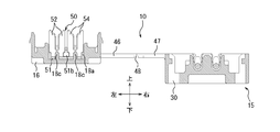
- FIG. 1 is a perspective view of the branch connector 10, the first cable 60, and the second cable 65 in a state where the insulating housing 15 according to the embodiment is in an unfolded state.
- 2 is a cross-sectional view taken along the line II of FIG.
- the branch connector 10 of this embodiment includes an insulating housing 15 and a relay contact 50 as large components.
- the insulating housing 15 is a molded product made of, for example, an insulating synthetic resin material.
- the insulating housing 15 integrally includes a first divided housing 16, a second divided housing 30, and a first connecting portion 46 and a second connecting portion 47 as a connecting portion that connects the first divided housing 16 and the second divided housing 30. Have been molded.
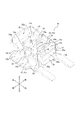
- FIG. 3 is an enlarged perspective view of only the first divided housing 16 in a state where the relay contact 50 is not provided.
- segmentation housing 16 is demonstrated in detail.
- the outer peripheral edge of one surface (the upper surface in FIG. 3) in the thickness direction of the first divided housing 16 is formed by the outer peripheral wall 17.
- the inner peripheral side of the outer peripheral wall 17 of the first divided housing 16 is constituted by an inner peripheral concave portion 17a that is recessed by one step from the upper surface of the first divided housing 16 (downward in FIG. 3).
- the bottom surface of the inner peripheral recess 17 a is configured by an inner peripheral first opposing surface 17 b that is a plane parallel to the upper surface of the first divided housing 16.
- the central portion located on the inner peripheral side from the inner peripheral first opposing surface 17b is constituted by a central first concave portion 17c that is recessed by one step from the inner peripheral first opposing surface 17b (downward in FIG. 3).
- the bottom surface of the central first concave portion 17c is constituted by a central first opposing surface 17d composed of a plane parallel to the inner peripheral first opposing surface 17b.
- a contact mounting groove 18 is formed by the central first recess 17c and the central first facing surface 17d.
- the contact mounting groove 18 has a fixed portion 18a and an intermediate convex portion 18b that is located in the middle in the left-right direction of the fixed portion 18a and narrows the front-back width of the fixed portion 18a to divide the fixed portion 18a into a pair of left and right.
- a substantially cylindrical positioning protrusion 18c is projected from the bottom surface (center first facing surface 17d) of the pair of fixing portions 18a.
- the outer peripheral wall 17 of the first divided housing 16 has a pair of first cable mounting grooves 19 located on both front and rear sides of one fixed portion 18a and on the same straight line, and on both front and rear sides of the other fixed portion 18a.
- a pair of second cable mounting grooves 20 that are positioned and collinear with each other (parallel to the first cable mounting groove 19) are recessed.
- the front shapes of the first cable mounting groove 19 and the second cable mounting groove 20 are semicircular.
- a pair of inclined surfaces 19 a that are inclined outward from the deepest bottom surface of the pair of first cable mounting grooves 19 are provided.
- a pair of inclined surfaces 20 a that are inclined outward from the deepest bottom surface of the pair of second cable attachment grooves 20 are provided.
- the front and rear surfaces of the outer peripheral wall 17 of the first divided housing 16 are provided with flat lid portions 21 and 22 that extend in the front-rear direction from a position below the front and rear inclined surfaces 19a and 20a.
- Opposing surfaces 21a and 22a (upper surfaces in FIG. 3) of the lid portions 21 and 22 are located at the same height as the lowermost portions of the inclined surfaces 19a and 20a.
- a pair of first lock portions 25 having elasticity are formed on the left and right side surfaces of the outer peripheral wall 17 of the first divided housing 16.
- a pair of concave portions 25 a is formed between each first lock portion 25 and the front and rear surfaces of the outer peripheral wall 17.
- Each first lock portion 25 has a first locking protrusion 26 that protrudes outward from the side surface of the first divided housing 16.
- the first locking projection 26 extends in the front-rear direction.
- Each of the first locking protrusions 26 has an inclined surface 26 a that is inclined outward from the first divided housing 16 as it goes downward.
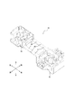
- FIG. 4 is an enlarged perspective view of only the second divided housing 30.
- the structure of the second divided housing 30 will be described in detail with reference to FIG.
- the outer peripheral wall 31 protrudes from the outer peripheral edge of one surface (the upper surface in FIG. 4) in the thickness direction of the second divided housing 30.
- a portion of the second divided housing 30 located on the inner peripheral side from the outer peripheral wall 31 is configured by an inner peripheral concave portion 31 a that is recessed by one step from the outer peripheral wall 31.
- the bottom surface of the inner circumferential recess 31 a is configured by an inner circumferential second opposing surface 31 b that is a plane parallel to the upper surface of the second divided housing 30.
- a cable pressing protrusion 32 having a pair of left and right U-shaped first pressing grooves 32a and a second pressing groove 32b protrudes from the inner peripheral second opposing surface 31b.
- the cable pressing protrusion 32 includes a central protrusion 32c and protrusions 32d and 32e formed on both left and right sides of the central protrusion 32c.
- a first pressing groove 32a is formed between the central protrusion 32c and one protrusion 32d.
- a second pressing groove 32b is formed between the central protrusion 32c and the other protrusion 32e.
- the second split housing 30 is formed with cable support arm portions 35 and 36 protruding from the front and rear surfaces.
- First cable holding grooves 35a and 36a and second cable holding grooves 35b and 36b are provided on the upper surfaces of the cable support arm portions 35 and 36, respectively.
- the front cable support arm portion 35 and the rear cable support arm portion 36 have a pair of projecting pieces 37a in which the front end side portion and the rear end side portion of the first cable holding grooves 35a and 36a are separated and divided into left and right by a gap. And a pair of protruding pieces 38a.
- the front cable support arm portion 35 and the rear cable support arm portion 36 have a pair of protruding pieces 37b in which the front end side portion and the rear end side portion of the second cable holding grooves 35b and 36b are separated and divided by a gap on the left and right. And a pair of protruding pieces 38b.
- Each of the pair of protruding pieces 37a, 38a, 37b, 38b, in particular, the left and right outer protruding pieces of the cable support arm portions 35, 36 are elastically bent in the left-right direction. Therefore, the interval between adjacent protruding pieces is variable.
- Each of the pair of projecting pieces 37a, 38a, 37b, and 38b has a claw portion that protrudes from the lower end portion of the front and rear end portions and faces each other.
- the first cable holding grooves 35a and 36a and the second cable holding grooves 35b and 36b are grooves having a depth for inserting and holding the first cable 60 and the second cable 65 over the entire diameter (the entire diameter can be accommodated). is there.
- the first cable holding grooves 35a and 36a have inclined surfaces 35e and 36e that are inclined upward toward the outside. That is, when the first cable 60 is inserted and held in the first cable holding grooves 35a and 36a, the first cable 60 is inclined by the inclined surfaces 35e and 36e of the first cable holding grooves 35a and 36a as shown in FIG. And incline in a diagonal direction at the corresponding cable portion.
- the second cable holding grooves 35b and 36b have inclined surfaces 35f and 36f.
- the second cable 65 is inserted and held in the second cable holding grooves 35 b and 36 b in the same manner as the first cable 60.
- a pair of drop-off prevention protrusions 35c and a pair of drop-out prevention protrusions 36c are provided near the upper opening portions of the front and rear ends of the first cable holding grooves 35a and 36a (the respective opposing surfaces of the protruding pieces 37a and 38a).
- a pair of drop-off prevention projections 35d and a pair of drop-off prevention projections 36d are provided near the upper openings (opposite surfaces of the protruding pieces 37b and 38b) of the front and rear ends of the second cable holding grooves 35b and 36b. It is done.
- the drop prevention protrusions 35c, 36c and 35d, 36d allow the first cable 60 and the second cable 65 to be inserted into the first cable holding grooves 35a, 36a and the second cable holding grooves 35b, 36b.
- the pair of projecting pieces 37a and 38a and the pair of projecting pieces 37b and 38b have an interval in the left-right direction (the distance between each pair of the drop-off prevention protrusions 35c and 36c and each pair of the drop-off prevention protrusions 35d and 36d). Bends to spread.
- each of the pair of protruding pieces 37a and 38a and each of the pair of protruding pieces 37b and 38b is elastically bent in a direction in which the distance between the left and right directions is narrowed. Accordingly, resistance is given to the first cable 60 and the second cable 65 inserted into the first cable holding grooves 35a and 36a and the second cable holding grooves 35b and 36b, and movement in the cable extension direction is allowed.
- each of the pair of protruding pieces 37a and 38a and each of the pair of protruding pieces 37b and 38b provides resistance to the force to be removed from the first cable holding grooves 35a and 36a and the second cable holding grooves 35b and 36b. Acts as a stopper to prevent it from coming off easily.
- each of the pair of protruding pieces 37a and 38a and each of the pair of protruding pieces 37b and 38b enables the first cable 60 and the second cable 65 to be detached by an external force of a certain level or more. The above-described retaining action is maintained even when the upper and lower sides (front and back) of the second divided housing 30 are reversed.
- a pair of second lock portions 39 are formed on the left and right side surfaces of the outer peripheral wall 31 of the second divided housing 30.
- the pair of second lock portions 39 is formed on the inner surface of the second divided housing 30.
- Each second lock portion 39 has a second locking projection 40 that protrudes inward from the side surface of the second divided housing 30.
- a pair of convex walls 41 extending in the vertical direction are formed at both front and rear ends of each second lock portion 39.
- Each of the second locking projections 40 has a substantially rectangular parallelepiped shape, and is formed above the inner surface of the second divided housing 30 so as to extend between the pair of convex walls 41. That is, the second locking protrusion 40 extends in the front-rear direction.
- a pair of hole portions 43 are formed on both left and right edges of the inner peripheral second opposing surface 31b so as to be adjacent to the second lock portions 39 on both left and right sides. Each hole 43 penetrates from the surface of the inner peripheral second opposing surface 31 b to the outer surface of the second divided housing 30.
- FIG. 5 is a perspective view showing the entire insulating housing 15 in a state where the relay contact 50 is not provided.
- the first divided housing 16 and the second divided housing 30 are a pair of front and rear first connection portions 46 linearly extending from the first divided housing 16 side, and a pair of front and rear first extending linearly from the second divided housing 30 side.
- the two connecting portions 47 are connected to each other by an easily bendable portion 48 that connects the first connecting portion 46 and the second connecting portion 47.
- the pair of front and rear first connection portions 46 and the pair of front and rear second connection portions 47 are located on the same plane in the deployed state.
- the bendable portion 48 is thinner than the front and rear first connection portions 46 and second connection portions 47.
- the front and rear first connection portions 46 and the second connection portion 47 are valley-folded (the first divided housing 16 and the second divided housing 30 in FIG. 1, FIG. 5, etc.) with the bendable portion 48 extending in the front-rear direction as a fold line. Can be folded in the direction of approaching (possible).
- the bending rigidity of the first connection portion 46 is set to be smaller than the bending rigidity of the second connection portion 47.
- the first divided housing 16, the first connection portion 46, the bendable portion 48, the second connection portion 47, and the second divided housing 30 autonomously maintain this expanded state in the expanded state shown in FIGS. Strength (rigidity)
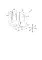
- FIG. 6 is a perspective view of the relay contact 50 alone. The structure of the relay contact 50 will be described in detail with reference to FIG.
- the relay contact 50 is obtained by forming a thin plate of a copper alloy having spring elasticity (for example, phosphor bronze, beryllium copper, or titanium copper) or a Corson copper alloy into a shape shown in the drawing using a progressive die (stamping). In the relay contact 50, after a base is formed on the surface by nickel plating, tin copper plating, tin plating, or gold plating is performed.
- a copper alloy having spring elasticity for example, phosphor bronze, beryllium copper, or titanium copper
- Corson copper alloy for example, phosphor bronze, beryllium copper, or titanium copper
- a progressive die stamping
- the relay contact 50 includes a flat plate-like base piece 51 extending in the left-right direction and a pair of flat plate-like shapes extending in a direction perpendicular to the base piece 51 and projecting from one end of both front and rear edges of the base piece 51.
- a first cable pressure contact piece 52, and a pair of flat second cable pressure contact pieces 54 that project from the other ends of the front and rear side edges of the base piece 51 and extend in a direction orthogonal to the base piece 51. are integrally provided.
- Circular positioning holes 51 a are formed at two positions on the left and right of the base piece 51.
- the first and second first and second cable pressure contact pieces 52 and 54 are respectively formed with a first pressure contact groove 53 and a second pressure contact groove 55 formed by a slit extending linearly toward the base piece 51 side. Is done.
- the upper end opening of the first pressure contact groove 53 is formed in a substantially V shape that widens upward by the tip 52a.
- the upper end opening of the second pressure contact groove 55 is formed in a substantially V shape that widens upward by the tip end portion 54a.
- the pair of front and rear first cable pressure contact pieces 52 and the pair of front and rear second cable pressure contact pieces 54 are connected to the base piece 51 via a narrow portion 52b and a narrow portion 54b, respectively.
- the distance between the opposed edge portions of the first cable pressure contact piece 52 and the second cable pressure contact piece 54 positioned in the left-right direction is narrower than the distance between the opposed edge portions of the narrow portion 52b and the narrow portion 54b.
- a play portion 51b is provided between the narrow portion 52b and the narrow portion 54b. No other member such as an insulator is interposed between the first cable pressure contact piece 52 and the second cable pressure contact piece 54.
- the relay contact 50 is included in a state in which the first divided housing 16 and the second divided housing 30 are in a conductive state with the first cable 60 and the second cable 65. More specifically, the relay contact 50 has an insulating covering 62 and a covering 67 by the first pressure contact groove 53 and the second pressure contact groove 55 when the first divided housing 16 and the second divided housing 30 are fitted.
- the first cable 60 and the second cable 65 are electrically connected to each other. That is, the relay contact 50 sandwiches the core wire 61 and the core wire 66 by the first press-contacting groove 53 and the second press-contacting groove 55, and electrically connects the first cable 60 and the second cable 65 to each other.
- the first cable 60 and the second cable 65 are tubular and flexible on the surfaces of core wires 61 and 66 (twisted wire or single wire) made of a conductive and flexible material (for example, copper or aluminum). And coverings 62 and 67 having electrical properties and insulating properties, respectively.
- the first cable 60 is a cable that is wired from the beginning inside a wiring object (for example, an automobile or the like) and connected to the power supply of the wiring object.
- the second cable 65 is a cable that is additionally connected to the first cable 60 later.
- An electronic device or an electric device (for example, a car navigation system) is connected to one end (front end) of the second cable 65.
- the filler 70 may be any material such as a waterproof gel, a UV curable resin, or an adhesive.
- the filler 70 will be described as an example of a UV curable resin having a waterproof function.
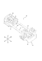
- FIG. 7 is a perspective view showing the branch connector 10 in which the filler 70 is loaded into the insulating housing 15 in the unfolded state.
- FIG. 8 is a perspective view showing a jig 80 for placing the insulating housing 15 before the filler 70 is loaded.
- a filler 70 is interposed between the inner peripheral first opposing surface 17 b of the first divided housing 16 and the inner peripheral second opposing surface 31 b of the second split housing 30.
- the surface shape of the filler 70 is formed in the first divided housing 16 and the second divided housing 30 so as to correspond to the respective inner surface shapes in a state where the first cable 60 and the second cable 65 are not placed. .
- the UV curable resin (filler 70) is a material that changes physical properties from a fluid state to an elastic state by irradiation with ultraviolet rays.
- the UV curable resin in the fluidized state is applied to the inner surfaces of the first divided housing 16 and the second divided housing 30 by a tool such as a dispenser. Since the UV curable resin has fluidity at this stage, the UV curable resin diffuses inside the first divided housing 16 and the second divided housing 30 so as to correspond to the inner surface shapes of the first divided housing 16 and the second divided housing 30.
- the surface shape of the UV curable resin is formed so as to correspond to the inner surface shapes of the first divided housing 16 and the second divided housing 30 in the flowing state. Thereafter, the UV curable resin changes its physical properties to an elastic state by irradiation with ultraviolet rays.
- the UV curable resin in a fluidized state is the second divided housing. Leak outside of 30. Therefore, a jig 80 is used to prevent resin leakage to the outside.
- the jig 80 has a first base 81 for placing the first divided housing 16 and a second base 82 for placing the second divided housing 30.
- the jig 80 is integrally formed so that the first base 81 and the second base 82 are continuous in the left-right direction.
- the vertical width of the first base 81 is larger than the vertical width of the second base 82.
- the jig 80 is formed such that the upper portion of the first base 81 protrudes upward from the upper surface of the second base 82.
- On the upper surface of the second base 82 a pair of protrusions 83 are formed that fit into the pair of holes 43 when the second divided housing 30 is placed.
- the vertical width between the upper surface of the first base 81 and the upper surface of the second base 82 matches the vertical width between the bottom surface of the first split housing 16 and the bottom surface of the second split housing 30. To do. That is, when the first divided housing 16 and the second divided housing 30 are placed on the jig 80, the pair of hole portions 43 of the second divided housing 30 are fitted with the pair of protrusions 83, and the first divided housing 16. And the bottom surface of the second divided housing 30 are in contact with the top surfaces of the first base 81 and the second base 82, respectively.
- the insulating housing 15 before being loaded with the UV curable resin is placed on the jig 80, and the pair of holes 43 of the second divided housing 30 are closed, and the UV is cured.
- the cured resin is applied.
- the surface shape of the UV curable resin corresponds to the shape of the upper surface of the protrusion 83 of the jig 80 in addition to the inner surface shape of the first divided housing 16 and the second divided housing 30 in the flowing state. It is formed.
- the filler 70 interposed in the inner peripheral first opposing surface 17b of the first divided housing 16 has the lower surface having a planar shape substantially the same as the inner peripheral first opposing surface 17b and surrounds the periphery of the relay contact 50. It is formed in a rectangular tube shape.
- the height of the filler 70 is a height at which the fillers 70 are in close contact with each other when the first divided housing 16 and the second divided housing 30 are closed.
- the filler 70 interposed on the inner peripheral second opposing surface 31 b of the second divided housing 30 has a lower surface having a planar shape substantially the same as the inner peripheral second opposing surface 31 b and surrounds the cable pressing protrusion 32. It is formed in a rectangular tube shape.
- the height of the filler 70 is a height at which the fillers 70 are in close contact with each other when the first divided housing 16 and the second divided housing 30 are closed.
- FIG. 9 is a perspective view of the branch connector 10, the first cable 60, and the second cable 65 when the insulating housing 15 transitions from the deployed state to the locked state.
- FIG. 10 is a perspective view of the branch connector 10, the first cable 60, and the second cable 65 when the insulating housing 15 is in a locked state.
- 11 is a cross-sectional view taken along the line II-II in FIG.
- the insulating housing 15, the relay contact 50, the first cable 60, the second cable 65, and the filler 70 are integrated, and the branch connector 10 is assembled while the first cable 60 and the second cable 65 are electrically connected.
- the assembly operator first fits the lower part of the relay contact 50 into the contact mounting groove 18 of the first divided housing 16 in the unfolded state shown in FIG. Specifically, the base piece 51 is fitted to the bottom of the contact mounting groove 18 while the play portion 51b is fitted to the intermediate convex portion 18b.
- the half part (the lower half part in FIGS. 1 and 2) of the first cable pressure contact piece 52 on the base piece 51 side is fitted to the corresponding fixing part 18a.
- the relay contact 50 is positioned with respect to the first divided housing 16.
- the front and rear first pressure contact grooves 53 are positioned on the axis passing through the front and rear first cable attachment grooves 19.
- the front and rear second pressure welding grooves 55 are positioned on the axis passing through the front and rear second cable mounting grooves 20.
- the assembly operator pushes against the resistance by the front and rear drop-off preventing projections 35c, 36c and 35d, 36d by hand or the like (see FIG. 1). At that time, each of the projecting pieces 37a, 38a, 37b, 38b bends against the elastic force and widens the gap between the anti-drop-off projections 35c, 36c and 35d, 36d.
- the first cable 60 and the second cable 65 are pushed into the first cable holding grooves 35a, 36a and the second cable holding grooves 35b, 36b, the gaps between the drop-off prevention protrusions 35c, 36c and 35d, 36d are narrowed.
- the first cable 60 and the second cable 65 are located between the bottoms of the first cable holding grooves 35a and 36a and the bottoms of the second cable holding grooves 35b and 36b and the drop-off preventing projections 35c, 36c and 35d, 36d. It is pinched. As a result, the first cable 60 and the second cable 65 are movable in the cable extension direction while receiving resistance. Therefore, it is possible to adjust the positions of the first cable 60 and the second cable 65 in the extending direction with respect to the branch connector 10 in the unfolded state shown in FIGS. The first cable 60 and the second cable 65 receive resistance that prevents the first cable holding grooves 35a and 36a and the second cable holding grooves 35b and 36b from being detached.
- the branch connector 10 is turned upside down, the first cable 60 and the second cable 65 do not easily fall out of the first cable holding grooves 35a and 36a and the second cable holding grooves 35b and 36b.
- the first cable 60 and the second cable 65 can be separated from the first cable holding grooves 35a and 36a and the second cable holding grooves 35b and 36b by an urging force of a certain level or more. Therefore, the replacement of the branch connector 10 and the change of the first cable 60 and the second cable 65 attached to and detached from the branch connector 10 are easy.
- the first cable 60 and the second cable 65 are arranged side by side in the left-right direction, with the first cable holding grooves 35a, 36a and the second cable holding grooves 35b, 36b fitted and held, with the front and rear bendable portions 48 as the center.
- the second divided housing 30 front and rear second connecting portions 47
- the second locking projection 40 on the first divided housing 16 side comes into contact with the inclined surface 26 a of the corresponding first locking projection 26.
- the corresponding first locking protrusion 26 is elastically deformed inward of the first divided housing 16 while the second locking protrusion 40 slides downward on the corresponding inclined surface 26a.
- the second pressing groove 32b of the cable pressing protrusion 32 located on the second connection portion 47 side slightly pushes the intermediate portion of the second cable 65 into the back side (downward) of the second pressure welding groove 55.
- the intermediate portion of the second cable 65 enters the space between the front and rear second cable pressure contact pieces 54.
- the cable pressing protrusion 32 When the second divided housing 30 is further rotated by a hand or the like in the direction approaching the first divided housing 16 around the front and rear bendable portions 48, the cable pressing protrusion 32 positioned on the opposite side to the second connection portion 47.
- the first pressing groove 32a presses the intermediate portion of the first cable 60 against the distal end portion 52a of the first cable pressing piece 52 in the extending direction of the first pressing groove 53 or a direction close thereto. Therefore, the first cable 60 is sandwiched between the distal end portion 52 a and the cable pressing protrusion 32.
- the first divided housing 16 and the second divided housing are used by a general tool (for example, a pliers) (not shown). 30 are pressed substantially parallel to the directions approaching each other. At this time, each second locking protrusion 40 engages with the corresponding first locking protrusion 26. Each convex wall 41 of the 2nd lock part 39 fits with the corresponding recessed part 25a.
- the first divided housing 16 is accommodated in the second divided housing 30, and the first lock portion 25 and the second lock portion 39 are located inside the fitted first divided housing 16 and second divided housing 30. Engage.
- the cable pressing protrusion 32 further pushes the intermediate portion of the first cable 60 and the second cable 65 into the back side (bottom side) of the first pressure contact groove 53 and the second pressure contact groove 55. Accordingly, the first cable 60 is pushed from the distal end portion 52 a to the substantially central portion of the first pressure contact groove 53, and the second cable 65 is pushed from the distal end portion 54 a to the substantially central portion of the second pressure contact groove 55. At this time, the pressing direction of the first cable 60 and the second cable 65 by the first pressing groove 32a and the second pressing groove 32b of the cable pressing protrusion 32 is the vertical direction (the first pressing groove 53 and the second pressing groove 55). Direction).
- both the left and right sides of the covering 62 of the first cable 60 are broken by the inner surface (left and right both sides) of the first pressure welding groove 53 and the second cable 65 is covered by the inner surface (left and right both sides) of the second pressure welding groove 55.
- the left and right sides of 67 are broken. Therefore, when the insulating housing 15 is held in the closed state, the inner surfaces (a pair of opposing surfaces) of the first pressure contact groove 53 are in uniform and reliable contact (pressure contact) with both sides of the core wire 61, and the first The inner surfaces (a pair of opposing surfaces) of the two pressure contact grooves 55 are in uniform and reliable contact (pressure contact) with both side portions of the core wire 66. That is, the core wire 61 of the first cable 60 and the core wire 66 of the second cable 65 are electrically connected to each other through the relay contact 50 inside the branch connector 10.
- the inner surfaces of the first press contact groove 53 and the second press contact groove 55 do not excessively hit against one of the both side portions of the core wires 61 and 66, a part of the core wires 61 and 66 is part of the first press contact groove. 53 and the second pressure contact groove 55 are not cut. Therefore, since the mechanical strength of the core wires 61 and 66 does not decrease, there is little possibility that the core wires 61 and 66 are completely cut even if a tensile force is applied to the first cable 60 and the second cable 65. Therefore, the contact reliability between the first cable 60 and the second cable 65 and the relay contact 50 can be improved.
- the facing surfaces 21a and 22a of the lid portions 21 and 22 of the first divided housing 16 are Part of the opening (the upper opening in FIG. 4) of the first cable holding grooves 35a and 36a and the second cable holding grooves 35b and 36b is blocked.
- the first cable 60 is sandwiched between the pair of inclined surfaces 19a of the first divided housing 16 and the corresponding inclined surfaces 35e and 36e of the second divided housing 30 from above and below.
- the second cable 65 is sandwiched between the pair of inclined surfaces 20 a of the first divided housing 16 and the corresponding inclined surfaces 35 f and 36 f of the second divided housing 30 from above and below.
- the relay contact 50 connects the first cable pressure contact piece 52 and the second cable pressure contact piece 54 and the base piece 51 by the narrow portions 52b and 54b.
- the gap (interval) between the first cable pressure contact piece 52 and the second cable pressure contact piece 54 is narrow, and an insulator or the like is not disposed in this gap. Therefore, the size of the relay contact 50, particularly the width in the left-right direction is reduced, and a reduction in size and weight is possible.
- the branch connector 10 When the branch connector 10 is shifted from the expanded state shown in FIG. 7 to the locked state, the entire interior of the fitted first divided housing 16 and second divided housing 30 is filled with the filler 70 as shown in FIG. . More specifically, when the first divided housing 16 and the second divided housing 30 are in a locked state, the filler 70 is applied to the inner peripheral first opposing surface 17b and the inner peripheral second opposing surface 31b. The periphery of the relay contact 50 is sealed tightly. The filler 70 surrounds the surfaces of the coverings 62 and 67 of the first cable 60 and the second cable 65 (without hindering electrical conduction with the relay contact 50).
- the first cable 60 and the second cable 65 extend outward from the relay contact 50 disposed inside the filler 70 in a locked state. That is, the first cable 60 and the second cable 65 extend outward from the pressure contact portion of the relay contact 50 along the front-rear direction.
- the filler 70 contacts the inner surfaces of the pair of first lock portions 25 of the first divided housing 16.
- the engaging surfaces 27 of the first locking projections 26 and the second locking projections 40 are configured to be positioned within the width of the filler 70 along the vertical direction in the vertical direction. Is preferred.
- the surface of the second locking projection 40 comes into contact with the outer surface of the first locking portion 25. It is preferable that the contact surface 42 formed thereby is substantially parallel to the inner surface of the first lock portion 25 that contacts the filler 70.
- the branch connector 10 does not need to be molded with the filler 70 as a separate member and is applied in a fluid state like a UV curable resin, the inner surface of the first divided housing 16 and the second divided housing 30 and the surface of the filler 70 are applied. It is difficult to form voids or air bubbles between the two. Since there is no direct contact with the filler 70 in the manufacturing process, there is no possibility that foreign matter adheres to the filler 70 or the shape of the filler 70 changes. Therefore, the branch connector 10 can make the filler 70 adhere to the inner surfaces of the first divided housing 16 and the second divided housing 30, and can improve waterproofness.
- the branch connector 10 can apply the filler 70 with a simple operation using a tool such as a dispenser, variation in assembly accuracy by the manufacturer can be suppressed. Since the branch connector 10 does not need to be molded with the filler 70 as a separate member, the number of man-hours can be reduced and the working time can be shortened.
- the branch connector 10 can be loaded with the filler 70 in accordance with various variations of the inner surface shape by using the corresponding jig 80.
- a UV curable resin as the filler 70, the resin can be changed to an elastic state only by irradiation with ultraviolet rays, so that the operation becomes simpler.
- the branch connector 10 can be loaded with the filler 70 corresponding to the internal shape of each product, and can maintain the waterproof property for each product.
- the filler 70 is in close contact with the first cable 60 and the second cable 65, even if the first cable 60 and the second cable 65 are bent and bent by an external force applied outside the branch connector 10, the first cable Transmission of movement or stress due to bending of the 60 and the second cable 65 to the pressure contact portion with the relay contact 50 is suppressed. Thereby, contact reliability is maintained.
- the branch connector 10 When the filler 70 comes into contact with the inner surface of the first lock portion 25, the first lock portion 25 having elasticity will be elastically deformed outward by an elastic force from the inside to the outside due to expansion or swelling of the filler 70. And since the branch connector 10 includes a lock portion on the inner side, the branch connector 10 can further strengthen the engagement between the first lock portion 25 and the second lock portion 39 by elastic deformation outward. More specifically, the engagement surface 27 of the first locking projection 26 and the second locking projection 40 is within the width in the vertical direction of the inner surface of the first lock portion 25 that contacts the filler 70, so The expansion force or the like of the agent 70 can be efficiently converted into the engagement force.
- the branch connector 10 can convert the expansion force or the like of the filler 70 into the engagement force more efficiently.
- the branch connector 10 can further enhance the close contact state between the first divided housing 16 and the second divided housing 30.
- the branch connector 10 can suppress the opening action of the first divided housing 16 and the second divided housing 30 even when the elastic force from the inside to the outside is applied.
- the branch connector 10 can maintain waterproofness. The effect appears even at room temperature, but becomes more prominent as the expansion of the filler 70 increases at higher temperatures.
- the branch connector 10 can further suppress the opening between the first divided housing 16 and the second divided housing 30. That is, the fillers 70 are arranged on both sides of the first divided housing 16 and the second divided housing 30 so that the respective fillers 70 adhere to each other in the locked state, and the first divided housing into which the adhesive force is fitted. 16 and the resistance against the opening of the second divided housing 30.
- the branch connector 10 has a locking mechanism formed inside the fitted first divided housing 16 and second divided housing 30, the outer peripheral wall 31 can be formed in a substantially planar shape with few irregularities or through holes. Thereby, the branch connector 10 can further improve waterproofness, and can further suppress entry of foreign matter such as dust and oil.
- the branch connector 10 is configured such that the first locking protrusion 26 extending in one direction and the second locking protrusion 40 extending in the same direction are engaged, and the engaging surface 27 extends in the same direction. By doing so, the area of the engagement surface 27 can be expanded and the engagement can be further strengthened.
- the engaging surface 27 is substantially horizontal as shown in FIG. 11, so that the engaging force is easily transmitted between the first locking protrusion 26 and the second locking protrusion 40.
- the jig 80 is described as being formed in a shape as shown in FIG. 8, but is not limited thereto.
- the jig 80 may have any shape as long as the shape corresponds to the shape of the insulating housing 15 and the filler 70 does not leak to the outside.
- FIG. 12 is an enlarged cross-sectional view corresponding to FIG. 11, in which the engaging portion between the first lock portion 25 and the second lock portion 39 according to another embodiment is enlarged.
- the engagement surfaces 27 of the first locking protrusions 26 and the second locking protrusions 40 are substantially horizontal planes extending in the front-rear direction, but are not limited thereto.
- the engagement surface 27 may be inclined downward from the inside to the outside of the fitted first divided housing 16 and the second divided housing 30.
- the branch connector 10 can further reduce the possibility of unlocking due to the cross-sectional shape.
- the first lock portion 25 is formed in the first divided housing 16 and the second lock portion 39 is formed in the second divided housing 30, but the present invention is not limited to this. Even if the first lock portion 25 having elasticity is formed on the second divided housing 30 side without the relay contact 50, the second lock portion 39 is formed on the first split housing 16 side having the relay contact 50. Good.
- the formation positions of the first lock portion 25 and the second lock portion 39 in the first split housing 16 and the second split housing 30 are not limited to the above, and the first split housing 16 and the second split housing 30 are fitted together. As long as it is possible to hold the lock, it may be in any formation position.
- first lock portion 25 and the second lock portion 39 have a first locking projection 26 and a second locking projection 40, respectively.
- the present invention is not limited to this.
- the 1st lock part 25 and the 2nd lock part 39 may have arbitrary locking means.
- the drop-off preventing projections 35c, 36c and 35d, 36d for preventing the first cable 60 and the second cable 65 from dropping are provided in the first cable holding grooves 35a, 36a and the second cable holding grooves 35b, 36b.
- the drop prevention protrusions may be provided in the first pressing groove 32a and the second pressing groove 32b of the cable pressing protrusion 32, respectively.
- the relay contact 50 is a type that presses the second cable 65, but may be a type that crimps the second cable 65.
- the second cable 65 is crimped to the relay contact 50 in advance, and the relay contact 50 is attached to the first divided housing 16 in this state.
- a cable crimping terminal is formed instead of one of the pair of first pressure contact grooves 53 and second pressure contact grooves 55 of the relay contact 50.
- the second split housing 30 is provided with one cable support arm portion 35 or 36 corresponding to the remaining pressure contact groove.
- three or more cables arranged in a direction orthogonal or substantially orthogonal to the extending direction of the portion supported by the branch connector 10 of each cable may be connected by the branch connector 10.
- three or more pairs of pressure contact grooves (aligned in the left-right direction) may be formed in one relay contact.
- a pressure contact groove may be formed in each of the plurality of relay contacts, and two or more pairs of pressure contact grooves may be formed in at least one relay contact, and the cable (core wire) may be pressure contacted by each pressure contact groove.
Landscapes
- Chemical & Material Sciences (AREA)
- Dispersion Chemistry (AREA)
- Connector Housings Or Holding Contact Members (AREA)
- Connections By Means Of Piercing Elements, Nuts, Or Screws (AREA)
- Manufacturing Of Electrical Connectors (AREA)
Abstract
充填剤を装填する個体ごとに防水性を維持できる分岐コネクタを提供する。 接続部(46、47)で接続された嵌合可能な一対の分割ハウジング(16、30)と、一対の分割ハウジング(16、30)内に装填される充填剤(70)と、を備え、充填剤(70)の表面形状は、一対の分割ハウジング(16、30)の内面形状に対応するように、一対の分割ハウジング(16、30)内において形成される。
Description
本出願は、2016年5月25日に日本国に特許出願された特願2016-104341号の優先権を主張するものであり、これら先の出願の開示全体をここに参照のために取り込む。
本発明は、電子機器又は電気機器に接続された既存のケーブル(電線)に対して、当該電線とは別のケーブル(電線)を接続するための分岐コネクタに関する。
この種の分岐コネクタは、絶縁性(合成樹脂製)のハウジングと、ハウジングに支持した導電性(金属製)の中継コンタクトと、を具備している。ハウジングは、第一分割ハウジングと、第二分割ハウジングと、第一分割ハウジングと第二分割ハウジングとを互いに接離可能として接続する接続部と、第一分割ハウジングと第二分割ハウジングとが接触したときにこの接触状態を保持するロック部と、を一体的に有する。
大別して、2つのタイプの中継コンタクトが知られている。1つは、既存のケーブル(電線)を圧接する圧接用溝と、当該ケーブル(電線)とは別のケーブル(電線)を圧着する圧着端子とを有するタイプである(特許文献1)。別のタイプは、既存のケーブル(電線)と、別のケーブル(電線)とをそれぞれ圧接する一対の圧接用溝を並列に有するタイプである(特許文献2)。
いずれのタイプでも、第一分割ハウジング及び第二分割ハウジングのいずれか一方に中継コンタクトが保持される。その圧接用溝にケーブルを接続する際には、該中継コンタクトの圧接用溝の上(入口部)に圧接されるケーブルを載置した状態で保持し、その状態で他方の分割ハウジングを中継コンタクト(を有する分割ハウジング)上に重ねて嵌め合わせる。これにより、中継コンタクトの圧接用溝によってケーブルの被覆を切断し、芯線と中継コンタクトとを導通させている。
一方で、上記のような分岐コネクタにおいて、防水機能の付加に対する要求が高まっている。これに対して、第一分割ハウジング及び第二分割ハウジングを接触させた際に、防水用ゲル又はUV硬化樹脂等の充填剤が各分割ハウジング内に装填されるように構成することが考えられる。このとき、充填剤を別部材として成形した後に、分割ハウジング内に装填する方法が考えられる。
しかしながら、上記のような方法では、主に2つの問題点があった。
一点目は、組立て性の問題である。すなわち、分割ハウジングの内面形状及び充填剤の形状は、製造工程における精度の限界によって、実際には個体ごとにばらつく。これにより、充填剤の装填時に、充填剤と分割ハウジングの内面とを空隙なく密着させた状態で組立てることが困難であった。また、別部材として組立てることで、組立工数が増え、組立時間がより長くなる。さらに、製造者ごとの組立精度のばらつきも大きい。
二点目は、防水性の問題である。すなわち、別部材として充填剤を成形してから分割ハウジングに装填するまでの間に、充填剤に埃等の異物が付着するおそれがある。また、上述のとおり、充填剤と分割ハウジングの内面とを空隙なく密着させた状態で組立てることは困難である。結果として、分岐コネクタの防水性が低減することとなる。
かかる観点に鑑みてなされた本発明の目的は、充填剤を装填する個体ごとに防水性を維持できる分岐コネクタを提供することにある。
上記課題を解決する第1の観点に係る分岐コネクタは、
接続部で接続された嵌合可能な一対の分割ハウジングと、
前記一対の分割ハウジング内に装填される充填剤と、
を備え、
前記充填剤の表面形状は、前記一対の分割ハウジングの内面形状に対応するように、前記一対の分割ハウジング内において形成される。
接続部で接続された嵌合可能な一対の分割ハウジングと、
前記一対の分割ハウジング内に装填される充填剤と、
を備え、
前記充填剤の表面形状は、前記一対の分割ハウジングの内面形状に対応するように、前記一対の分割ハウジング内において形成される。
第2の観点に係る分岐コネクタでは、
前記充填剤は、流動状態から弾性状態に物性を変化させる材料によって構成され、前記流動状態において、前記一対の分割ハウジングの前記内面形状に対応するように前記表面形状が形成された後、前記弾性状態に物性が変化する。
前記充填剤は、流動状態から弾性状態に物性を変化させる材料によって構成され、前記流動状態において、前記一対の分割ハウジングの前記内面形状に対応するように前記表面形状が形成された後、前記弾性状態に物性が変化する。
第3の観点に係る分岐コネクタでは、
前記一対の分割ハウジングの少なくとも一方は、内面から外面へと貫通する穴部を備え、
前記充填剤の前記表面形状は、前記一対の分割ハウジングを、前記穴部に対応する突部を形成した治具に載置して、前記穴部を塞いだ状態で形成される。
前記一対の分割ハウジングの少なくとも一方は、内面から外面へと貫通する穴部を備え、
前記充填剤の前記表面形状は、前記一対の分割ハウジングを、前記穴部に対応する突部を形成した治具に載置して、前記穴部を塞いだ状態で形成される。
第4の観点に係る分岐コネクタでは、
前記充填剤は、紫外線の照射により前記流動状態から前記弾性状態に前記物性を変化させる材料によって構成される。
前記充填剤は、紫外線の照射により前記流動状態から前記弾性状態に前記物性を変化させる材料によって構成される。
第5の観点に係る分岐コネクタでは、
前記一対の分割ハウジングのいずれか一方は、電気導通部を有するコンタクトを備え、
前記一対の分割ハウジングのいずれか一方は、ケーブルを保持し、
前記コンタクトは、前記一対の分割ハウジングの嵌合状態において、前記ケーブルと導通した状態で内包される。
前記一対の分割ハウジングのいずれか一方は、電気導通部を有するコンタクトを備え、
前記一対の分割ハウジングのいずれか一方は、ケーブルを保持し、
前記コンタクトは、前記一対の分割ハウジングの嵌合状態において、前記ケーブルと導通した状態で内包される。
第6の観点に係る分岐コネクタでは、
少なくとも1本の前記ケーブルが、嵌合時に前記充填剤の内側に配置される前記コンタクトから外側に延出する。
少なくとも1本の前記ケーブルが、嵌合時に前記充填剤の内側に配置される前記コンタクトから外側に延出する。
第7の観点に係る分岐コネクタでは、
前記電気導通部は、圧接用溝であり、
前記一対の分割ハウジングのいずれか一方は、少なくとも2本の前記ケーブルを保持し、
前記コンタクトは、前記一対の分割ハウジングの嵌合時に、前記圧接用溝によって前記ケーブルの芯線を挟持して、前記ケーブル同士を導通させる。
前記電気導通部は、圧接用溝であり、
前記一対の分割ハウジングのいずれか一方は、少なくとも2本の前記ケーブルを保持し、
前記コンタクトは、前記一対の分割ハウジングの嵌合時に、前記圧接用溝によって前記ケーブルの芯線を挟持して、前記ケーブル同士を導通させる。
本発明によれば、充填剤を装填する個体ごとに防水性を維持できる分岐コネクタを提供可能である。
以下、添付図面を参照しながら一実施形態について説明する。初めに、充填剤を装填していない状態の分岐コネクタの構造について主に説明する。以下の説明中の前後、左右、及び上下の方向は、図中の矢印の方向を基準としている。
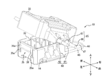
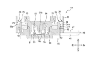
図1は、一実施形態の絶縁ハウジング15が展開状態にある分岐コネクタ10、第一ケーブル60、及び第二ケーブル65の斜視図である。図2は、図1のI-I矢線に沿う断面図である。本実施形態の分岐コネクタ10は、大きな構成要素として絶縁ハウジング15と中継コンタクト50とを具備している。
絶縁ハウジング15は、例えば絶縁性の合成樹脂材料により構成した成形品である。絶縁ハウジング15は、第一分割ハウジング16、第二分割ハウジング30、並びに第一分割ハウジング16と第二分割ハウジング30とを接続する連結部としての第一接続部46及び第二接続部47を一体的に成形して有する。
図3は、中継コンタクト50を具備しない状態の第一分割ハウジング16のみを拡大した斜視図である。図3を参照して、第一分割ハウジング16の構造を詳細に説明する。
第一分割ハウジング16の厚み方向の一方の面(図3の上面)の外周縁部は、外周壁17により形成される。第一分割ハウジング16の外周壁17より内周側は、第一分割ハウジング16の上面より(図3の下方へ)一段凹んだ内周側凹部17aにより構成される。内周側凹部17aの底面は、第一分割ハウジング16の上面と平行な平面からなる内周側第一対向面17bにより構成される。この内周側第一対向面17bより内周側に位置する中央部分は、内周側第一対向面17bより(図3の下方へ)一段凹んだ中央第一凹部17cにより構成される。中央第一凹部17cの底面は、内周側第一対向面17bと平行な平面からなる中央第一対向面17dにより構成される。中央第一凹部17cと中央第一対向面17dとにより、コンタクト取付溝18が形成される。コンタクト取付溝18は、固定部18aと、固定部18aの左右方向中間に位置し、固定部18aの前後幅を狭めて固定部18aを左右一対に区切る中間凸部18bと、を有している。一対の固定部18aの底面(中央第一対向面17d)には略円柱形状の位置決め突起18cが突設される。
第一分割ハウジング16の外周壁17には、一方の固定部18aの前後両側に位置しかつ互いに同一直線上に位置する一対の第一ケーブル取付溝19と、他方の固定部18aの前後両側に位置しかつ互いに同一直線上に位置する(第一ケーブル取付溝19と平行をなす)一対の第二ケーブル取付溝20と、が凹設される。第一ケーブル取付溝19及び第二ケーブル取付溝20の正面形状は半円形である。第一分割ハウジング16の外周壁17の前後面には、一対の第一ケーブル取付溝19の最深底面から下方に向かって外側に傾斜する一対の傾斜面19aが設けられる。同様に、第一分割ハウジング16の外周壁17の前後面には、一対の第二ケーブル取付溝20の最深底面から下方に向かって外側に傾斜する一対の傾斜面20aが設けられる。第一分割ハウジング16の外周壁17の前後面には、前後の傾斜面19a、20aより下方位置から前後方向に延びた平板状の蓋部21、22が設けられる。蓋部21、22の対向面21a、22a(図3の上方の面)は、傾斜面19a、20aの最下部と同一の高さに位置する。
第一分割ハウジング16の外周壁17の左右両側面には、弾性を有する一対の第一ロック部25が形成される。各第一ロック部25と外周壁17の前後面との間には、一対の凹部25aが形成される。各第一ロック部25は、第一分割ハウジング16の側面から外側に突出する第一ロック用突起26を有する。第一ロック用突起26は、前後方向に延在している。各第一ロック用突起26は、下方に向かうに従って第一分割ハウジング16の外側に傾斜する傾斜面26aを有する。
図4は、第二分割ハウジング30のみを拡大した斜視図である。図4を参照して、第二分割ハウジング30の構造を詳細に説明する。
第二分割ハウジング30の厚み方向の一方の面(図4の上面)の外周縁部には、外周壁31が突設される。第二分割ハウジング30の外周壁31より内周側に位置する部分は、外周壁31より一段凹んだ内周側凹部31aにより構成される。内周側凹部31aの底面は、第二分割ハウジング30の上面と平行な平面からなる内周側第二対向面31bにより構成される。内周側第二対向面31bには、左右一対の断面U字形の第一押圧溝32a及び第二押圧溝32bを有するケーブル押圧突起32が突設される。ケーブル押圧突起32は、中央突起32cと、中央突起32cの左右方向両側に形成される突起32d、32eと、を有する。中央突起32cと一方の突起32dとの間に、第一押圧溝32aが形成される。中央突起32cと他方の突起32eとの間に、第二押圧溝32bが形成される。
第二分割ハウジング30には、前後面から突出するケーブル支持腕部35、36が形成される。ケーブル支持腕部35、36の上面には、第一ケーブル保持溝35a、36aと第二ケーブル保持溝35b、36bとが設けられる。前方側のケーブル支持腕部35及び後方側のケーブル支持腕部36は、第一ケーブル保持溝35a及び36aの前端側部分及び後端側部分が、左右に空隙により分離分割した一対の突出片37a及び一対の突出片38aによって形成される。前方側のケーブル支持腕部35及び後方側のケーブル支持腕部36は、第二ケーブル保持溝35b及び36bの前端側部分及び後端側部分が、左右に空隙により分離分割した一対の突出片37b及び一対の突出片38bによって形成される。各一対の突出片37a、38a、37b、38b、特にケーブル支持腕部35、36の左右外側の突出片は、左右方向に弾性的に撓む。したがって、隣接する突出片同士の間隔は、可変である。各一対の突出片37a、38a、37b、38bは、前後端部の下端部から突設され、互いに対向する爪部を有する。
第一ケーブル保持溝35a、36aと第二ケーブル保持溝35b、36bとは、第一ケーブル60と第二ケーブル65とを全径に渡って挿入保持する(全径が収まる)深さの溝である。第一ケーブル保持溝35a、36aは、外側に向かうに従って上方に傾斜する傾斜面35e、36eを有する。すなわち、第一ケーブル60が、第一ケーブル保持溝35a、36aに挿入保持されると、第一ケーブル60は、図1に示すように、第一ケーブル保持溝35a、36aの傾斜面35e、36eに沿って、対応するケーブル部分において上下斜め方向に傾斜する。同様に、第二ケーブル保持溝35b、36bは、傾斜面35f、36fを有する。第二ケーブル65は、第一ケーブル60と同様の態様で、第二ケーブル保持溝35b、36bに挿入保持される。
第一ケーブル保持溝35a、36aの前後端部の上方開口部寄り(突出片37a、38aの各対向面)には、一対の脱落防止突起35cと一対の脱落防止突起36cとが設けられる。同様に、第二ケーブル保持溝35b、36bの前後端部の上方開口部寄り(突出片37b、38bの各対向面)には、一対の脱落防止突起35dと一対の脱落防止突起36dとが設けられる。脱落防止突起35c、36c及び35d、36dは、第一ケーブル60及び第二ケーブル65が第一ケーブル保持溝35a、36a及び第二ケーブル保持溝35b、36bに挿入されるのを許容する。このとき、各一対の突出片37a、38a及び各一対の突出片37b、38bは、左右方向の間隔(各一対の脱落防止突起35c、36c及び各一対の脱落防止突起35d、36dの間隔)が広がるように撓む。
第一ケーブル60及び第二ケーブル65が第一ケーブル保持溝35a、36a及び第二ケーブル保持溝35b、36bに挿入されると、一対の脱落防止突起35c、36c及び一対の脱落防止突起35d、36dが第一ケーブル60及び第二ケーブル65を挟圧する。このとき、各一対の突出片37a、38a及び各一対の突出片37b、38bは、弾性的に左右方向の間隔が狭まる方向に撓む。したがって、第一ケーブル保持溝35a、36a及び第二ケーブル保持溝35b、36bに挿入された第一ケーブル60及び第二ケーブル65に対して抵抗が与えられつつ、ケーブル延長方向への移動が許容される。加えて、各一対の突出片37a、38a及び各一対の突出片37b、38bは、第一ケーブル保持溝35a、36a及び第二ケーブル保持溝35b、36bから離脱しようとする力に抵抗を与えて容易に抜けないように抜け止めとして作用する。一方で、各一対の突出片37a、38a及び各一対の突出片37b、38bは、一定以上の外力による第一ケーブル60及び第二ケーブル65の離脱を可能とする。上記の抜止作用は、第二分割ハウジング30の上下(表裏)を反転させても維持される。
第二分割ハウジング30の外周壁31の左右両側面には、一対の第二ロック部39が形成される。一対の第二ロック部39は、第二分割ハウジング30の内面に形成される。各第二ロック部39は、第二分割ハウジング30の側面から内側に突出する第二ロック用突起40を有する。各第二ロック部39の前後両端には、上下方向に延在する一対の凸壁41が形成される。各第二ロック用突起40は、略直方体形状であり、一対の凸壁41間にわたるように、第二分割ハウジング30の内面の上方に形成される。すなわち、第二ロック用突起40は、前後方向に延在する。
内周側第二対向面31bの左右両縁部には、左右両側面の第二ロック部39に隣接するように一対の穴部43が形成される。各穴部43は、内周側第二対向面31bの表面から第二分割ハウジング30の外面まで貫通している。
図5は、中継コンタクト50を具備しない状態の絶縁ハウジング15全体を示す斜視図である。
第一分割ハウジング16と第二分割ハウジング30とは、第一分割ハウジング16側から直線的に延びる前後一対の第一接続部46と、第二分割ハウジング30側から直線的に延びる前後一対の第二接続部47と、第一接続部46と第二接続部47とを接続する屈曲容易部48とによって連結される。前後一対の第一接続部46及び前後一対の第二接続部47は、展開状態で互いに同一平面上に位置する。
図2及び図5に示すように屈曲容易部48は、前後の第一接続部46及び第二接続部47より薄肉としてある。前後の第一接続部46及び第二接続部47は、前後方向に延びる屈曲容易部48を折曲げ線として、図1、図5等において谷折り(第一分割ハウジング16と第二分割ハウジング30とが接近する方向に折曲げ)可能(容易)である。第一接続部46の曲げ剛性は、第二接続部47の曲げ剛性よりも小さくなるように設定される。
第一分割ハウジング16、第一接続部46、屈曲容易部48、第二接続部47、及び第二分割ハウジング30は、図1及び図5に示す展開状態において、自律的にこの展開状態を維持する程度の強度(剛性)を有する。
図6は、中継コンタクト50単体の斜視図である。図6を参照して、中継コンタクト50の構造を詳細に説明する。
中継コンタクト50は、ばね弾性を有する銅合金(例えばリン青銅、ベリリウム銅、若しくはチタン銅)又はコルソン系銅合金の薄板を順送金型(スタンピング)を用いて図示形状に成形加工したものである。中継コンタクト50では、表面にニッケルメッキで下地が形成された後に、錫銅めっき、錫めっき、又は金めっきが施される。
中継コンタクト50は、左右方向に延びる平板状の基片51と、基片51の前後両側縁部の一方の端部に突設した、基片51に対して直交する方向に延びる平板状の一対の第一ケーブル圧接片52と、基片51の前後両側縁部の他方の端部に突設した、基片51に対して直交する方向に延びる平板状の一対の第二ケーブル圧接片54と、を一体的に有する。基片51の左右二か所には円形の位置決め孔51aが形成される。前後の第一ケーブル圧接片52と第二ケーブル圧接片54とには、基片51側に向かって直線的に延びるスリットからなる第一圧接用溝53と第二圧接用溝55とがそれぞれ形成される。第一圧接用溝53の上端開口部は、先端部52aにより上方に向かって広がる略V字状に形成される。第二圧接用溝55の上端開口部は、先端部54aにより上方に向かって広がる略V字状に形成される。
前後一対の第一ケーブル圧接片52及び前後一対の第二ケーブル圧接片54は、それぞれ幅狭部52b及び幅狭部54bを介して基片51と接続される。左右方向に位置する第一ケーブル圧接片52と第二ケーブル圧接片54との対向縁部の間隔は、幅狭部52bと幅狭部54bとの対向縁部の間隔より狭い。幅狭部52bと幅狭部54bとの間には、遊び部51bが設けられる。第一ケーブル圧接片52と第二ケーブル圧接片54との間には、インシュレータ等の他の部材が介在しない。
中継コンタクト50は、第一分割ハウジング16と第二分割ハウジング30との嵌合状態において、第一ケーブル60及び第二ケーブル65と導通した状態で内包される。より具体的には、中継コンタクト50は、第一分割ハウジング16と第二分割ハウジング30との嵌合時に、第一圧接用溝53及び第二圧接用溝55によって絶縁性の被覆62及び被覆67を切断して、第一ケーブル60及び第二ケーブル65同士を導通接続するものである。すなわち、中継コンタクト50は、嵌合時に、第一圧接用溝53及び第二圧接用溝55によって芯線61及び芯線66を挟持して、第一ケーブル60及び第二ケーブル65同士を導通させる。
第一ケーブル60及び第二ケーブル65は、導電性及び可撓性を有する材料(例えば銅又はアルミニウム)からなる芯線61、66(撚り線又は単線)の表面を、チューブ状であり、かつ可撓性及び絶縁性を有する被覆62、67でそれぞれ覆ったものである。第一ケーブル60は、配線対象物(例えば自動車等)の内部に最初から配線しかつ配線対象物の電源と接続するケーブルである。一方、第二ケーブル65は、第一ケーブル60に対して後から追加で接続するケーブルである。第二ケーブル65の一端(前端)には電子機器又は電気機器(例えばカーナビゲーションシステム)等が接続される。
以下では、充填剤70を装填した状態の分岐コネクタ10について主に説明する。充填剤70は、防水用ゲル、UV硬化樹脂、又は接着剤等、任意の材料であってよい。以下では、充填剤70は、一例として、防水機能を有するUV硬化樹脂であるものとして説明する。
図7は、展開状態における絶縁ハウジング15に充填剤70を装填した分岐コネクタ10を示す斜視図である。図8は、充填剤70を装填する前の絶縁ハウジング15を載置するための治具80を示す斜視図である。
本実施形態では、図7に示すように、第一分割ハウジング16の内周側第一対向面17b及び第二分割ハウジング30の内周側第二対向面31bに、充填剤70を介在させる。充填剤70の表面形状は、第一ケーブル60及び第二ケーブル65を載置しない状態で、第一分割ハウジング16及び第二分割ハウジング30内において、それぞれの内面形状に対応するように形成される。
より詳細には、UV硬化樹脂(充填剤70)は、紫外線の照射により流動状態から弾性状態に物性を変化させる材料である。流動状態におけるUV硬化樹脂は、ディスペンサー等の工具により第一分割ハウジング16及び第二分割ハウジング30の内面に塗布される。UV硬化樹脂は、この段階では流動性を有しているので、第一分割ハウジング16及び第二分割ハウジング30の内面形状に対応するように、それぞれの内部で拡散する。このように、UV硬化樹脂の表面形状は、流動状態において、第一分割ハウジング16及び第二分割ハウジング30の内面形状に対応するように形成される。その後、紫外線の照射によって、UV硬化樹脂は、弾性状態にその物性を変化させる。
本実施形態に係る分岐コネクタ10のように、例えば、UV硬化樹脂の塗布領域に穴部43のような外面まで貫通する構造が存在する場合、流動状態にあるUV硬化樹脂は、第二分割ハウジング30の外部に漏れる。そこで、外部への樹脂漏れを防ぐために、治具80を用いる。
治具80は、第一分割ハウジング16を載置するための第一基台81と、第二分割ハウジング30を載置するための第二基台82とを有する。治具80は、第一基台81と第二基台82とが左右方向に連続するように一体成形されている。第一基台81の上下方向の幅は、第二基台82の上下方向の幅よりも大きい。治具80は、第一基台81の上部が、第二基台82の上面から上方に突出するように形成される。第二基台82の上面には、第二分割ハウジング30を載置した時に一対の穴部43と嵌合する一対の突部83が形成される。第一基台81の上面と第二基台82の上面との間の上下方向の幅は、第一分割ハウジング16の底面と第二分割ハウジング30の底面との間の上下方向の幅に一致する。すなわち、第一分割ハウジング16及び第二分割ハウジング30を治具80に載置した時、第二分割ハウジング30の一対の穴部43が一対の突部83と嵌合し、第一分割ハウジング16の底面及び第二分割ハウジング30の底面が、第一基台81及び第二基台82の上面とそれぞれ当接する。
本実施形態に係る分岐コネクタ10の場合、UV硬化樹脂を装填する前の絶縁ハウジング15を治具80に載置して、第二分割ハウジング30の一対の穴部43を塞いだ状態で、UV硬化樹脂は塗布される。このように、UV硬化樹脂の表面形状は、流動状態において、第一分割ハウジング16及び第二分割ハウジング30の内面形状に加えて、治具80の突部83の上面形状にも対応するように形成される。
第一分割ハウジング16の内周側第一対向面17bに介在させた充填剤70は、下面の平面形状が内周側第一対向面17bと略同一であって、中継コンタクト50の周囲を囲む角筒形状に形成される。充填剤70の高さは、第一分割ハウジング16と第二分割ハウジング30とを閉じたときに、それぞれの充填剤70同士が密着する高さである。
第二分割ハウジング30の内周側第二対向面31bに介在させた充填剤70は、下面の平面形状が内周側第二対向面31bと略同一であり、ケーブル押圧突起32の周囲を囲む角筒形状に形成される。充填剤70の高さは、第一分割ハウジング16と第二分割ハウジング30とを閉じたときに、それぞれの充填剤70同士が密着する高さである。
図9は、絶縁ハウジング15が展開状態からロック状態に遷移する段階の分岐コネクタ10、第一ケーブル60、及び第二ケーブル65の斜視図である。図10は、絶縁ハウジング15がロック状態にあるときの分岐コネクタ10、第一ケーブル60、及び第二ケーブル65の斜視図である。図11は、図10のII-II矢線に沿う断面図である。
絶縁ハウジング15、中継コンタクト50、第一ケーブル60、第二ケーブル65、及び充填剤70を一体化して、第一ケーブル60と第二ケーブル65とを電気的に接続しながら分岐コネクタ10を組み立てる。そのためには、まず組み立て作業者が手等により図7に示す展開状態にある第一分割ハウジング16のコンタクト取付溝18に対して中継コンタクト50の下部を嵌合させる。具体的には、遊び部51bを中間凸部18bに嵌合させながら、基片51をコンタクト取付溝18の底部に嵌合させる。第一ケーブル圧接片52の基片51側の半部(図1、図2では下半部)を対応する固定部18aに嵌合させる。同様に、第二ケーブル圧接片54の基片51側の半部を対応する固定部18aに嵌合させる。基片51の一対の位置決め孔51aに対して第一分割ハウジング16の一対の位置決め突起18cが嵌合するので(図2、図11)、中継コンタクト50が第一分割ハウジング16に対して位置決めされる。中継コンタクト50を第一分割ハウジング16に取り付けると、前後の第一ケーブル取付溝19を通る軸線上に前後の第一圧接用溝53が位置する。同様に、前後の第二ケーブル取付溝20を通る軸線上に前後の第二圧接用溝55が位置する。
組み立て作業者が手等により、前後の脱落防止突起35c、36c及び35d、36dによる抵抗に抗して押込む(図1参照)。その際、各突出片37a、38a、37b、38bは弾性力に抗して撓み、対向する脱落防止突起35c、36c及び35d、36dの間隔を広げる。第一ケーブル60及び第二ケーブル65が第一ケーブル保持溝35a、36a及び第二ケーブル保持溝35b、36bに押し込まれると、対向する脱落防止突起35c、36c及び35d、36dの間隔が狭まる。これにより、第一ケーブル60及び第二ケーブル65は、第一ケーブル保持溝35a、36aの底部及び第二ケーブル保持溝35b、36bの底部と脱落防止突起35c、36c及び35d、36dとの間に挟持される。これにより第一ケーブル60及び第二ケーブル65は、抵抗を受けながらケーブル延長方向に移動可能である。したがって、図1及び図2に示した展開状態の分岐コネクタ10に対する第一ケーブル60及び第二ケーブル65の延長方向の位置調整が可能である。第一ケーブル60及び第二ケーブル65は、第一ケーブル保持溝35a、36a及び第二ケーブル保持溝35b、36bから離脱しようとすると離脱を阻止する抵抗を受ける。したがって、分岐コネクタ10を上下逆さまにしても、第一ケーブル60及び第二ケーブル65は、第一ケーブル保持溝35a、36a及び第二ケーブル保持溝35b、36bから容易に抜け落ちない。第一ケーブル60及び第二ケーブル65は、一定以上の付勢力により第一ケーブル保持溝35a、36a及び第二ケーブル保持溝35b、36bから離脱させることが可能である。したがって、分岐コネクタ10の交換、並びに分岐コネクタ10に着脱する第一ケーブル60及び第二ケーブル65の変更が容易である。
第一ケーブル60及び第二ケーブル65を左右方向に並べ、第一ケーブル保持溝35a、36a及び第二ケーブル保持溝35b、36bに嵌合保持した状態のまま、前後の屈曲容易部48を中心に第二分割ハウジング30(前後の第二接続部47)を第一分割ハウジング16(前後の第一接続部46)に対して接近するように回転させる。すると、第一分割ハウジング16側の第二ロック用突起40が、対応する第一ロック用突起26の傾斜面26aに当接する。さらに回転させると、当該第二ロック用突起40が対応する傾斜面26aを下方に摺動しつつ、対応する第一ロック用突起26が、第一分割ハウジング16の内側方向に弾性変形する。一方で、第二接続部47側に位置するケーブル押圧突起32の第二押圧溝32bが、第二ケーブル65の中間部を、第二圧接用溝55の奥側(下方)に僅かに押し込むことで、第二ケーブル65の中間部が、前後の第二ケーブル圧接片54の間の空間に入り込む。
手等により第二分割ハウジング30を前後の屈曲容易部48を中心に第一分割ハウジング16に対して接近する方向にさらに回転させると、第二接続部47と反対側に位置するケーブル押圧突起32の第一押圧溝32aが、第一ケーブル60の中間部を第一ケーブル圧接片52の先端部52aに対して第一圧接用溝53の延出方向又はこれに近い方向に押し当てる。したがって、第一ケーブル60が先端部52aとケーブル押圧突起32とによって挟持される。
第一ケーブル60と第二ケーブル65とを中継コンタクト50の先端部52a、54aに載置した後に、図示を省略した一般的な工具(例えば、プライヤー)によって第一分割ハウジング16及び第二分割ハウジング30を、互いに接近する方向に略平行に押圧する。このとき、各第二ロック用突起40が、対応する第一ロック用突起26に対して係合する。第二ロック部39の各凸壁41が、対応する凹部25aと嵌合する。これにより、第一分割ハウジング16が第二分割ハウジング30内に収容され、第一ロック部25と第二ロック部39とは、嵌合した第一分割ハウジング16及び第二分割ハウジング30の内側で係合する。
ケーブル押圧突起32は、第一ケーブル60及び第二ケーブル65の中間部を第一圧接用溝53及び第二圧接用溝55の奥側(底面側)にさらに押し込む。したがって、第一ケーブル60が先端部52aから第一圧接用溝53の略中央部まで押し込まれかつ第二ケーブル65が先端部54aから第二圧接用溝55の略中央部まで押し込まれる。このとき、ケーブル押圧突起32の第一押圧溝32a及び第二押圧溝32bによる第一ケーブル60及び第二ケーブル65の押圧方向は、上下方向(第一圧接用溝53及び第二圧接用溝55の延長方向)と略平行となる。これにより、第一圧接用溝53の内面(左右両面)によって第一ケーブル60の被覆62の左右両側部が破られかつ第二圧接用溝55の内面(左右両面)によって第二ケーブル65の被覆67の左右両側部が破られる。したがって、絶縁ハウジング15が閉状態に保持されたときに、第一圧接用溝53の内面(一対の対向面)が芯線61の両側部に対して均等且つ確実に接触(圧接)し、かつ第二圧接用溝55の内面(一対の対向面)が芯線66の両側部に対して均等且つ確実に接触(圧接)する。すなわち、分岐コネクタ10の内部において第一ケーブル60の芯線61と第二ケーブル65の芯線66とが中継コンタクト50を介して互いに電気的に導通する。
芯線61、66の両側部の一方に対して第一圧接用溝53及び第二圧接用溝55の内面が過度に強く当たることがないので、芯線61、66の一部が第一圧接用溝53及び第二圧接用溝55によって切断されることがない。そのため芯線61、66の機械的強度が低下しないので、第一ケーブル60及び第二ケーブル65に引張力が作用しても芯線61、66が完全に切断するおそれは小さい。したがって、第一ケーブル60及び第二ケーブル65と中継コンタクト50との接触信頼性を高めることが可能である。
第一分割ハウジング16と第二分割ハウジング30とが閉状態に(嵌合して)保持(ロック)された状態では、第一分割ハウジング16の蓋部21、22の対向面21a、22aが、第一ケーブル保持溝35a、36a及び第二ケーブル保持溝35b、36bの開口部(図4の上方の開口部)の一部を塞いでいる。第一ケーブル60は、第一分割ハウジング16の一対の傾斜面19a、及び対応する第二分割ハウジング30の傾斜面35e、36eによって上下方向から挟持される。同様に、第二ケーブル65は、第一分割ハウジング16の一対の傾斜面20a、及び対応する第二分割ハウジング30の傾斜面35f、36fによって上下方向から挟持される。このように構成すると、第一分割ハウジング16と第二分割ハウジング30とが閉状態(ロック状態)となったときに、第一ケーブル60及び第二ケーブル65の被覆62、67の表面に(中継コンタクト50との電気的導通を妨げることなく)密着する。したがって、仮に分岐コネクタ10の外側において加わった外力によって第一ケーブル60及び第二ケーブル65が振られて屈曲したとしても、第一ケーブル60及び第二ケーブル65の屈曲に起因する動き又は応力の中継コンタクト50との圧接部に対する伝達が抑止される。これにより、接触信頼性が維持される。
中継コンタクト50は、第一ケーブル圧接片52及び第二ケーブル圧接片54と基片51とを幅狭部52b、54bで接続する。第一ケーブル圧接片52と第二ケーブル圧接片54との隙間(間隔)は狭く、この隙間にインシュレータ等が配置されない。したがって、中継コンタクト50の大きさ、特に左右方向の幅が小さくなり、小型軽量化が可能である。
図7に示す展開状態から、分岐コネクタ10をロック状態に遷移させると、図11に示すとおり、嵌合した第一分割ハウジング16及び第二分割ハウジング30の内部全体が充填剤70により充填される。より詳細には、第一分割ハウジング16と第二分割ハウジング30とがロック状態となったときに、充填剤70は、内周側第一対向面17bと内周側第二対向面31bとに密着して中継コンタクト50の周囲を密閉する。充填剤70は、第一ケーブル60及び第二ケーブル65の被覆62、67の表面を(中継コンタクト50との電気的導通を妨げることなく)囲む。
第一ケーブル60及び第二ケーブル65は、ロック状態で充填剤70の内側に配置される中継コンタクト50から外側に延出する。すなわち、第一ケーブル60及び第二ケーブル65は、中継コンタクト50における圧接部分から前後方向に沿って外側に延出する。
充填剤70は、第一分割ハウジング16の一対の第一ロック部25の内面と当接する。図11に示すとおり、第一ロック用突起26及び第二ロック用突起40の係合面27は、その上下方向において、上下方向に沿った充填剤70の幅内に位置するように構成されるのが好適である。第一分割ハウジング16及び第二分割ハウジング30を嵌め合わせたときに、第二ロック用突起40の表面は、第一ロック部25の外面と当接する。これにより形成される当接面42は、充填剤70と当接する第一ロック部25の内面と略平行であるのが好適である。
以上のような充填剤70の構成により、水又は埃等が第一ケーブル60及び第二ケーブル65の芯線61、66に接触するおそれを低減できる。
分岐コネクタ10は、充填剤70を別部材として成形する必要がなく、UV硬化樹脂のように流動状態で塗布するため、第一分割ハウジング16及び第二分割ハウジング30の内面と充填剤70の表面との間に空隙又は空泡が形成されにくい。製造工程において充填剤70に直接触れることがないので、充填剤70に異物が付着したり、充填剤70の形状が変化したりするおそれもない。したがって、分岐コネクタ10は、第一分割ハウジング16及び第二分割ハウジング30の内面に充填剤70を密着させることが可能であり、防水性を向上させることが可能である。
分岐コネクタ10は、ディスペンサー等の工具により単純な作業で充填剤70を塗布できるので、製造者による組立精度のばらつきを抑制できる。分岐コネクタ10は、充填剤70を別部材として成形する必要がないので、工数を低減でき、作業時間を短縮できる。分岐コネクタ10は、対応する治具80を用いることによって、様々なバリエーションの内面形状に合わせて、充填剤70を装填できる。充填剤70としてUV硬化樹脂を用いることで、紫外線の照射のみによって樹脂を弾性状態に変化させることが可能なので、作業がより簡易となる。
以上のように、分岐コネクタ10は、製品個体ごとの内部形状に対応させて充填剤70を装填可能であり、製品個体ごとに防水性を維持できる。
充填剤70が第一ケーブル60及び第二ケーブル65に密着するので、仮に分岐コネクタ10の外側において加わった外力によって第一ケーブル60及び第二ケーブル65が振られて屈曲したとしても、第一ケーブル60及び第二ケーブル65の屈曲に起因する動き又は応力の中継コンタクト50との圧接部に対する伝達が抑止される。これにより、接触信頼性が維持される。
充填剤70が、第一ロック部25の内面と当接することで、弾性を有する第一ロック部25は、充填剤70の膨張又は膨潤による内側から外側への弾性力により、外側に弾性変形しようとする。分岐コネクタ10では内側でロック部が構成されるので、外側への弾性変形により、分岐コネクタ10は、第一ロック部25と第二ロック部39との係合をさらに強固にすることができる。より詳述すると、第一ロック用突起26及び第二ロック用突起40の係合面27が、充填剤70と当接する第一ロック部25の内面の上下方向における幅内にあることで、充填剤70の膨張力等を効率良く係合力に変換できる。当接面42が充填剤70と当接する第一ロック部25の内面と略平行となることで、充填剤70の膨張力等は、第一ロック部25及び第二ロック用突起40の表面に対して略垂直方向に伝わる。これにより、分岐コネクタ10は、充填剤70の膨張力等をさらに効率良く係合力に変換できる。その結果、分岐コネクタ10は、第一分割ハウジング16及び第二分割ハウジング30の密着状態をより高めることができる。このように、分岐コネクタ10は、内側から外側への弾性力が働いた状態であっても、第一分割ハウジング16及び第二分割ハウジング30の開き作用を抑制できる。その結果、分岐コネクタ10は、防水性を維持できる。当該効果は、常温下においても現れるが、高温下において充填剤70の膨張が大きくなるほど、より顕著に現れる。
充填剤70として粘度が高い部材を使用する場合、分岐コネクタ10は、第一分割ハウジング16及び第二分割ハウジング30間の開きをさらに抑制できる。すなわち、第一分割ハウジング16及び第二分割ハウジング30の両側に充填剤70が配置されることで、ロック状態でそれぞれの充填剤70が粘着し、当該粘着力が、嵌合した第一分割ハウジング16及び第二分割ハウジング30の開きに対する抵抗力となる。
分岐コネクタ10は、嵌合した第一分割ハウジング16及び第二分割ハウジング30の内部にロック機構を形成したため、凹凸又は貫通穴が少ない略平面形状に外周壁31を形成することができる。これにより、分岐コネクタ10は、防水性をより高めることができ、粉塵及びオイル等の異物の侵入もさらに抑止できる。
分岐コネクタ10は、一方向に延在する第一ロック用突起26及び同方向に延在する第二ロック用突起40が係合して、係合面27が同方向に延在した平面を構成することで、係合面27の面積を広げ、係合をより強固にすることができる。分岐コネクタ10は、係合面27が図11に示すように略水平となることで、係合する力を第一ロック用突起26及び第二ロック用突起40間で伝えやすくなる。
本発明は、その精神又はその本質的な特徴から離れることなく、上述した実施形態以外の他の所定の形態で実現できることは当業者にとって明白である。したがって、先の記述は例示的なものであり、これに限定されるものではない。発明の範囲は、先の記述によってではなく、付加した請求項によって定義される。あらゆる変更のうちその均等の範囲内にあるいくつかの変更は、その中に包含されるものとする。
本実施形態では、治具80は図8のような形状により形成されるものとして説明したが、これに限定されない。治具80は、絶縁ハウジング15の形状に対応する形状であって、充填剤70が外部に漏れない構造であれば、任意の形状であってよい。
図12は、他の実施例に係る第一ロック部25と第二ロック部39との係合部を拡大した、図11に対応する拡大断面図である。上記では、図11に示すとおり、第一ロック用突起26及び第二ロック用突起40の係合面27は、前後方向に延在した略水平な平面であるが、これに限定されない。例えば、図12に示すとおり、当該係合面27が、嵌合した第一分割ハウジング16及び第二分割ハウジング30の内側から外側に向けて下方に傾斜していてもよい。分岐コネクタ10は、当該断面形状により、ロックが外れる可能性をさらに低減できる。
本実施形態では、第一ロック部25を第一分割ハウジング16に形成し、第二ロック部39を第二分割ハウジング30に形成しているが、これに限定されない。弾性を有する第一ロック部25が、中継コンタクト50を有さない第二分割ハウジング30側に形成され、第二ロック部39が、中継コンタクト50を有する第一分割ハウジング16側に形成されてもよい。第一ロック部25及び第二ロック部39の第一分割ハウジング16及び第二分割ハウジング30における形成位置も、上記に限定されず、第一分割ハウジング16及び第二分割ハウジング30を嵌合させてロックを保持することが可能であれば、任意の形成位置であってよい。
本実施形態では、第一ロック部25及び第二ロック部39は、第一ロック用突起26及び第二ロック用突起40をそれぞれ有し、第一ロック用突起26と第二ロック用突起40とが係合するロック手段を示したが、これに限定されない。第一ロック部25及び第二ロック部39は、任意のロック手段を有してもよい。
本実施形態では第一ケーブル60及び第二ケーブル65の脱落を防止する脱落防止突起35c、36c及び35d、36dを第一ケーブル保持溝35a、36a及び第二ケーブル保持溝35b、36bに設けたが、これに限定されない。脱落防止突起は、ケーブル押圧突起32の第一押圧溝32a及び第二押圧溝32bにそれぞれ設けてもよい。
中継コンタクト50は、第二ケーブル65を圧接するタイプであるが、第二ケーブル65を圧着するタイプであってもよい。この場合、第二ケーブル65は、予め中継コンタクト50に圧着接続しておき、この状態で中継コンタクト50を第一分割ハウジング16に装着する。この実施形態では、中継コンタクト50の一対の第一圧接用溝53及び第二圧接用溝55の一方の代わりに、ケーブル圧着端子が形成される。第二分割ハウジング30には、残存する圧接用溝に対応させて一つのケーブル支持腕部35又は36が設けられる。
逆に、各ケーブルの分岐コネクタ10によって支持された部位の延長方向に対して直交又は略直交する方向に並べた3本以上のケーブルが分岐コネクタ10により接続されてもよい。この場合、一つの中継コンタクトに(左右方向に並んだ)三対以上の圧接用溝が形成されてもよい。複数の中継コンタクトのそれぞれに圧接用溝が形成され、少なくとも一つの中継コンタクトに二対以上の圧接用溝が形成されて、各圧接用溝によってケーブル(芯線)が圧接されてもよい。
10 分岐コネクタ
15 絶縁ハウジング
16 第一分割ハウジング
17 外周壁
17a 内周側凹部
17b 内周側第一対向面
17c 中央第一凹部
17d 中央第一対向面
18 コンタクト取付溝
18a 固定部
18b 中間凸部
18c 位置決め突起
19 第一ケーブル取付溝
19a 傾斜面
20 第二ケーブル取付溝
20a 傾斜面
21、22 蓋部
21a、22a 対向面
25 第一ロック部
25a 凹部
26 第一ロック用突起
26a 傾斜面
27 係合面
30 第二分割ハウジング
31 外周壁
31a 内周側凹部
31b 内周側第二対向面
32 ケーブル押圧突起
32a 第一押圧溝
32b 第二押圧溝
32c 中央突起
32d、32e 突起
35、36 ケーブル支持腕部
35a、36a 第一ケーブル保持溝
35b、36b 第二ケーブル保持溝
35c、36c 脱落防止突起
35d、36d 脱落防止突起
35e、36e 傾斜面
35f、36f 傾斜面
37a、37b、38a、38b 突出片
39 第二ロック部
40 第二ロック用突起
41 凸壁
42 当接面
43 穴部
46 第一接続部(接続部)
47 第二接続部(接続部)
48 屈曲容易部
50 中継コンタクト
51 基片
51a 位置決め孔
51b 遊び部
52 第一ケーブル圧接片
52a 先端部
52b 幅狭部
53 第一圧接用溝(電気導通部、圧接用溝)
54 第二ケーブル圧接片
54a 先端部
54b 幅狭部
55 第二圧接用溝(電気導通部、圧接用溝)
60 第一ケーブル(ケーブル)
61 芯線
62 被覆
65 第二ケーブル(ケーブル)
66 芯線
67 被覆
70 充填剤
80 治具
81 第一基台
82 第二基台
83 突部
15 絶縁ハウジング
16 第一分割ハウジング
17 外周壁
17a 内周側凹部
17b 内周側第一対向面
17c 中央第一凹部
17d 中央第一対向面
18 コンタクト取付溝
18a 固定部
18b 中間凸部
18c 位置決め突起
19 第一ケーブル取付溝
19a 傾斜面
20 第二ケーブル取付溝
20a 傾斜面
21、22 蓋部
21a、22a 対向面
25 第一ロック部
25a 凹部
26 第一ロック用突起
26a 傾斜面
27 係合面
30 第二分割ハウジング
31 外周壁
31a 内周側凹部
31b 内周側第二対向面
32 ケーブル押圧突起
32a 第一押圧溝
32b 第二押圧溝
32c 中央突起
32d、32e 突起
35、36 ケーブル支持腕部
35a、36a 第一ケーブル保持溝
35b、36b 第二ケーブル保持溝
35c、36c 脱落防止突起
35d、36d 脱落防止突起
35e、36e 傾斜面
35f、36f 傾斜面
37a、37b、38a、38b 突出片
39 第二ロック部
40 第二ロック用突起
41 凸壁
42 当接面
43 穴部
46 第一接続部(接続部)
47 第二接続部(接続部)
48 屈曲容易部
50 中継コンタクト
51 基片
51a 位置決め孔
51b 遊び部
52 第一ケーブル圧接片
52a 先端部
52b 幅狭部
53 第一圧接用溝(電気導通部、圧接用溝)
54 第二ケーブル圧接片
54a 先端部
54b 幅狭部
55 第二圧接用溝(電気導通部、圧接用溝)
60 第一ケーブル(ケーブル)
61 芯線
62 被覆
65 第二ケーブル(ケーブル)
66 芯線
67 被覆
70 充填剤
80 治具
81 第一基台
82 第二基台
83 突部
Claims (7)
- 接続部で接続された嵌合可能な一対の分割ハウジングと、
前記一対の分割ハウジング内に装填される充填剤と、
を備え、
前記充填剤の表面形状は、前記一対の分割ハウジングの内面形状に対応するように、前記一対の分割ハウジング内において形成される、
分岐コネクタ。 - 前記充填剤は、流動状態から弾性状態に物性を変化させる材料によって構成され、前記流動状態において、前記一対の分割ハウジングの前記内面形状に対応するように前記表面形状が形成された後、前記弾性状態に物性が変化する、
請求項1に記載の分岐コネクタ。 - 前記一対の分割ハウジングの少なくとも一方は、内面から外面へと貫通する穴部を備え、
前記充填剤の前記表面形状は、前記一対の分割ハウジングを、前記穴部に対応する突部を形成した治具に載置して、前記穴部を塞いだ状態で形成される、
請求項2に記載の分岐コネクタ。 - 前記充填剤は、紫外線の照射により前記流動状態から前記弾性状態に前記物性を変化させる材料によって構成される、
請求項2又は3に記載の分岐コネクタ。 - 前記一対の分割ハウジングのいずれか一方は、電気導通部を有するコンタクトを備え、
前記一対の分割ハウジングのいずれか一方は、ケーブルを保持し、
前記コンタクトは、前記一対の分割ハウジングの嵌合状態において、前記ケーブルと導通した状態で内包される、
請求項1乃至4のいずれか1項に記載の分岐コネクタ。 - 少なくとも1本の前記ケーブルが、嵌合時に前記充填剤の内側に配置される前記コンタクトから外側に延出する、
請求項5に記載の分岐コネクタ。 - 前記電気導通部は、圧接用溝であり、
前記一対の分割ハウジングのいずれか一方は、少なくとも2本の前記ケーブルを保持し、
前記コンタクトは、前記一対の分割ハウジングの嵌合時に、前記圧接用溝によって前記ケーブルの芯線を挟持して、前記ケーブル同士を導通させる、
請求項5又は6に記載の分岐コネクタ。
Priority Applications (4)
| Application Number | Priority Date | Filing Date | Title |
|---|---|---|---|
| CN201780029509.0A CN109155486B (zh) | 2016-05-25 | 2017-05-25 | 分支连接器 |
| US16/303,104 US10680352B2 (en) | 2016-05-25 | 2017-05-25 | Branch connector |
| JP2017541747A JP6550467B2 (ja) | 2016-05-25 | 2017-05-25 | 分岐コネクタ |
| EP17802899.9A EP3467955B1 (en) | 2016-05-25 | 2017-05-25 | Branch connector |
Applications Claiming Priority (2)
| Application Number | Priority Date | Filing Date | Title |
|---|---|---|---|
| JP2016104341 | 2016-05-25 | ||
| JP2016-104341 | 2016-05-25 |
Publications (1)
| Publication Number | Publication Date |
|---|---|
| WO2017204313A1 true WO2017204313A1 (ja) | 2017-11-30 |
Family
ID=60412872
Family Applications (1)
| Application Number | Title | Priority Date | Filing Date |
|---|---|---|---|
| PCT/JP2017/019626 Ceased WO2017204313A1 (ja) | 2016-05-25 | 2017-05-25 | 分岐コネクタ |
Country Status (5)
| Country | Link |
|---|---|
| US (1) | US10680352B2 (ja) |
| EP (1) | EP3467955B1 (ja) |
| JP (1) | JP6550467B2 (ja) |
| CN (1) | CN109155486B (ja) |
| WO (1) | WO2017204313A1 (ja) |
Cited By (1)
| Publication number | Priority date | Publication date | Assignee | Title |
|---|---|---|---|---|
| JP2023180544A (ja) * | 2022-06-09 | 2023-12-21 | 澁谷工業株式会社 | ホログラフィ観察装置および試料保持容器 |
Families Citing this family (4)
| Publication number | Priority date | Publication date | Assignee | Title |
|---|---|---|---|---|
| JP6466983B2 (ja) * | 2017-03-22 | 2019-02-06 | 京セラ株式会社 | コネクタ |
| JP6466984B2 (ja) * | 2017-03-22 | 2019-02-06 | 京セラ株式会社 | コネクタ |
| JP6397962B1 (ja) * | 2017-05-24 | 2018-09-26 | 京セラ株式会社 | 梱包物 |
| JP6397965B1 (ja) * | 2017-06-19 | 2018-09-26 | 京セラ株式会社 | コネクタ |
Citations (6)
| Publication number | Priority date | Publication date | Assignee | Title |
|---|---|---|---|---|
| JPH04111110U (ja) * | 1991-03-14 | 1992-09-28 | 古河電気工業株式会社 | 自動車用電線の接続部 |
| JPH0664366U (ja) * | 1993-02-18 | 1994-09-09 | 日本エー・エム・ピー株式会社 | 圧接型コネクタ |
| JP3028988B2 (ja) | 1992-02-05 | 2000-04-04 | トヨタ自動車株式会社 | コネクタ |
| JP2605275Y2 (ja) | 1993-12-27 | 2000-07-04 | 京セラエルコ株式会社 | 電気コネクタのケーブル保護装置 |
| JP2006294486A (ja) * | 2005-04-13 | 2006-10-26 | Hitachi Mobile Co Ltd | 電線分岐端子および電線分岐方法 |
| JP2015060814A (ja) * | 2013-09-20 | 2015-03-30 | ホシデン株式会社 | コネクタ |
Family Cites Families (18)
| Publication number | Priority date | Publication date | Assignee | Title |
|---|---|---|---|---|
| GB9103902D0 (en) * | 1991-02-25 | 1991-04-10 | Raychem Sa Nv | Electrically-protected connector |
| US5147217A (en) * | 1991-06-18 | 1992-09-15 | General Motors Corporation | Electrical component package |
| JPH069065U (ja) * | 1992-07-06 | 1994-02-04 | 本田技研工業株式会社 | ワイヤハーネスの防水ジョイント構造 |
| JP3066713B2 (ja) * | 1995-02-09 | 2000-07-17 | 矢崎総業株式会社 | 圧接ジョイントコネクタ |
| JP3097819B2 (ja) * | 1995-07-04 | 2000-10-10 | 矢崎総業株式会社 | 圧接ジョイントコネクタ及びそれを用いたワイヤーハーネスの組立て方法 |
| JP3636393B2 (ja) * | 1995-10-31 | 2005-04-06 | ミネソタ マイニング アンド マニュファクチャリング カンパニー | 分岐コネクタ装置 |
| WO1998033241A1 (en) * | 1997-01-28 | 1998-07-30 | The Whitaker Corporation | Seal for an electrical connector, method for manufacturing a seal and use of a seal |
| JP3408391B2 (ja) * | 1997-04-02 | 2003-05-19 | 矢崎総業株式会社 | コネクタ |
| JP2000515677A (ja) * | 1997-05-22 | 2000-11-21 | トーマス アンド ベッツ インターナショナル,インク. | ケーブル・スプライス・クロージャ |
| DE19741603A1 (de) * | 1997-09-20 | 1999-03-25 | Volkswagen Ag | Elektrische Kontakteinrichtung sowie Verfahren zur Schneidkontaktherstellung |
| DE10142363A1 (de) * | 2001-08-30 | 2003-03-27 | Delphi Tech Inc | Elektrischer Verbinder |
| JP3889983B2 (ja) * | 2002-03-20 | 2007-03-07 | 矢崎総業株式会社 | コネクタ |
| US7384297B2 (en) * | 2006-11-07 | 2008-06-10 | King Jr Lloyd Herbert | Wire connector |
| US7686661B2 (en) * | 2008-07-31 | 2010-03-30 | Tyco Electronics Corporation | Connection enclosure assemblies, connector systems and methods for forming an enclosed connection between conductors |
| US7833038B1 (en) * | 2009-04-08 | 2010-11-16 | King Jr Lloyd Herbert | Inline push-in wire connectors |
| CN103066547A (zh) * | 2011-10-18 | 2013-04-24 | 上海市高桥电缆厂有限公司 | 电缆分支连接器 |
| US8967888B2 (en) * | 2012-04-25 | 2015-03-03 | Tyco Electronics Raychem Bvba | Dry silicone gels and their methods of making using thiol-ene chemistry |
| US20150171543A1 (en) * | 2013-12-13 | 2015-06-18 | General Electric Company | Sealed electrical connector assembly |
-
2017
- 2017-05-25 CN CN201780029509.0A patent/CN109155486B/zh active Active
- 2017-05-25 JP JP2017541747A patent/JP6550467B2/ja active Active
- 2017-05-25 US US16/303,104 patent/US10680352B2/en active Active
- 2017-05-25 WO PCT/JP2017/019626 patent/WO2017204313A1/ja not_active Ceased
- 2017-05-25 EP EP17802899.9A patent/EP3467955B1/en active Active
Patent Citations (6)
| Publication number | Priority date | Publication date | Assignee | Title |
|---|---|---|---|---|
| JPH04111110U (ja) * | 1991-03-14 | 1992-09-28 | 古河電気工業株式会社 | 自動車用電線の接続部 |
| JP3028988B2 (ja) | 1992-02-05 | 2000-04-04 | トヨタ自動車株式会社 | コネクタ |
| JPH0664366U (ja) * | 1993-02-18 | 1994-09-09 | 日本エー・エム・ピー株式会社 | 圧接型コネクタ |
| JP2605275Y2 (ja) | 1993-12-27 | 2000-07-04 | 京セラエルコ株式会社 | 電気コネクタのケーブル保護装置 |
| JP2006294486A (ja) * | 2005-04-13 | 2006-10-26 | Hitachi Mobile Co Ltd | 電線分岐端子および電線分岐方法 |
| JP2015060814A (ja) * | 2013-09-20 | 2015-03-30 | ホシデン株式会社 | コネクタ |
Non-Patent Citations (1)
| Title |
|---|
| See also references of EP3467955A4 |
Cited By (1)
| Publication number | Priority date | Publication date | Assignee | Title |
|---|---|---|---|---|
| JP2023180544A (ja) * | 2022-06-09 | 2023-12-21 | 澁谷工業株式会社 | ホログラフィ観察装置および試料保持容器 |
Also Published As
| Publication number | Publication date |
|---|---|
| EP3467955A4 (en) | 2020-01-01 |
| JP6550467B2 (ja) | 2019-07-24 |
| CN109155486B (zh) | 2020-06-05 |
| US20190319372A1 (en) | 2019-10-17 |
| CN109155486A (zh) | 2019-01-04 |
| EP3467955B1 (en) | 2024-07-17 |
| JPWO2017204313A1 (ja) | 2018-06-07 |
| EP3467955A1 (en) | 2019-04-10 |
| US10680352B2 (en) | 2020-06-09 |
Similar Documents
| Publication | Publication Date | Title |
|---|---|---|
| JP6397864B2 (ja) | 分岐コネクタ | |
| JP6397965B1 (ja) | コネクタ | |
| JP6495216B2 (ja) | 分岐コネクタ | |
| WO2017204313A1 (ja) | 分岐コネクタ | |
| JP6486419B2 (ja) | コネクタ | |
| JP6466984B2 (ja) | コネクタ | |
| JP6401869B1 (ja) | コネクタ | |
| JP6466983B2 (ja) | コネクタ | |
| JP6598810B2 (ja) | コネクタ | |
| JP6401770B2 (ja) | 分岐コネクタ | |
| WO2018173685A1 (ja) | コネクタ | |
| JP2018160457A (ja) | コネクタ |
Legal Events
| Date | Code | Title | Description |
|---|---|---|---|
| ENP | Entry into the national phase |
Ref document number: 2017541747 Country of ref document: JP Kind code of ref document: A |
|
| NENP | Non-entry into the national phase |
Ref country code: DE |
|
| 121 | Ep: the epo has been informed by wipo that ep was designated in this application |
Ref document number: 17802899 Country of ref document: EP Kind code of ref document: A1 |
|
| ENP | Entry into the national phase |
Ref document number: 2017802899 Country of ref document: EP Effective date: 20190102 |