WO2017204313A1 - Connecteur de dérivation - Google Patents
Connecteur de dérivation Download PDFInfo
- Publication number
- WO2017204313A1 WO2017204313A1 PCT/JP2017/019626 JP2017019626W WO2017204313A1 WO 2017204313 A1 WO2017204313 A1 WO 2017204313A1 JP 2017019626 W JP2017019626 W JP 2017019626W WO 2017204313 A1 WO2017204313 A1 WO 2017204313A1
- Authority
- WO
- WIPO (PCT)
- Prior art keywords
- cable
- pair
- filler
- divided housing
- branch connector
- Prior art date
- Legal status (The legal status is an assumption and is not a legal conclusion. Google has not performed a legal analysis and makes no representation as to the accuracy of the status listed.)
- Ceased
Links
Images




Classifications
-
- H—ELECTRICITY
- H01—ELECTRIC ELEMENTS
- H01R—ELECTRICALLY-CONDUCTIVE CONNECTIONS; STRUCTURAL ASSOCIATIONS OF A PLURALITY OF MUTUALLY-INSULATED ELECTRICAL CONNECTING ELEMENTS; COUPLING DEVICES; CURRENT COLLECTORS
- H01R4/00—Electrically-conductive connections between two or more conductive members in direct contact, i.e. touching one another; Means for effecting or maintaining such contact; Electrically-conductive connections having two or more spaced connecting locations for conductors and using contact members penetrating insulation
- H01R4/24—Connections using contact members penetrating or cutting insulation or cable strands
- H01R4/2416—Connections using contact members penetrating or cutting insulation or cable strands the contact members having insulation-cutting edges, e.g. of tuning fork type
- H01R4/242—Connections using contact members penetrating or cutting insulation or cable strands the contact members having insulation-cutting edges, e.g. of tuning fork type the contact members being plates having a single slot
- H01R4/2425—Flat plates, e.g. multi-layered flat plates
- H01R4/2429—Flat plates, e.g. multi-layered flat plates mounted in an insulating base
- H01R4/2433—Flat plates, e.g. multi-layered flat plates mounted in an insulating base one part of the base being movable to push the cable into the slot
-
- H—ELECTRICITY
- H01—ELECTRIC ELEMENTS
- H01R—ELECTRICALLY-CONDUCTIVE CONNECTIONS; STRUCTURAL ASSOCIATIONS OF A PLURALITY OF MUTUALLY-INSULATED ELECTRICAL CONNECTING ELEMENTS; COUPLING DEVICES; CURRENT COLLECTORS
- H01R13/00—Details of coupling devices of the kinds covered by groups H01R12/70 or H01R24/00 - H01R33/00
- H01R13/46—Bases; Cases
- H01R13/52—Dustproof, splashproof, drip-proof, waterproof, or flameproof cases
- H01R13/5216—Dustproof, splashproof, drip-proof, waterproof, or flameproof cases characterised by the sealing material, e.g. gels or resins
-
- H—ELECTRICITY
- H01—ELECTRIC ELEMENTS
- H01R—ELECTRICALLY-CONDUCTIVE CONNECTIONS; STRUCTURAL ASSOCIATIONS OF A PLURALITY OF MUTUALLY-INSULATED ELECTRICAL CONNECTING ELEMENTS; COUPLING DEVICES; CURRENT COLLECTORS
- H01R4/00—Electrically-conductive connections between two or more conductive members in direct contact, i.e. touching one another; Means for effecting or maintaining such contact; Electrically-conductive connections having two or more spaced connecting locations for conductors and using contact members penetrating insulation
- H01R4/70—Insulation of connections
Definitions
- This invention relates to the branch connector for connecting the cable (electric wire) different from the said electric wire with respect to the existing cable (electric wire) connected to the electronic device or the electric device.
- This type of branch connector has an insulating (synthetic resin) housing and a conductive (metal) relay contact supported on the housing.
- the housing is in contact with the first divided housing, the second divided housing, the connecting portion that connects the first divided housing and the second divided housing so as to be able to contact and separate from each other, and the first divided housing and the second divided housing.
- it integrally has a lock portion that maintains this contact state.
- relay contacts Two types are known. One is a type having a pressure welding groove for pressure-contacting an existing cable (electric wire) and a crimp terminal for crimping a cable (electric wire) different from the cable (wire) (Patent Document 1). Another type is a type having a pair of pressure welding grooves that press-fit an existing cable (electric wire) and another cable (electric wire) in parallel (Patent Document 2).
- the relay contact is held in either the first divided housing or the second divided housing.
- the cable When connecting the cable to the pressure contact groove, hold the cable to be pressed on the pressure contact groove (inlet part) of the relay contact and hold the other divided housing in the relay contact in that state. Fit over (split housing with).
- the cable sheath is cut by the pressure contact groove of the relay contact, and the core wire and the relay contact are made conductive.
- the first point is an assembly problem. That is, the shape of the inner surface of the divided housing and the shape of the filler actually vary from individual to individual due to the limit of accuracy in the manufacturing process. This makes it difficult to assemble the filler in a state in which the filler and the inner surface of the divided housing are in close contact with each other without a gap when the filler is loaded. Moreover, by assembling as a separate member, the number of assembling steps increases and the assembling time becomes longer. Furthermore, there is a large variation in assembly accuracy among manufacturers.
- the second point is the problem of waterproofness. That is, foreign matters such as dust may adhere to the filler between the time when the filler is molded as a separate member and the time when the filler is loaded into the divided housing. Further, as described above, it is difficult to assemble the filler and the inner surface of the divided housing in close contact with each other without a gap. As a result, the waterproofness of the branch connector is reduced.
- An object of the present invention made in view of such a viewpoint is to provide a branch connector capable of maintaining waterproofness for each individual loaded with a filler.
- the branch connector according to the first aspect for solving the above problem is A pair of mating split housings connected at the connecting portion; A filler loaded into the pair of split housings; With The surface shape of the filler is formed in the pair of split housings so as to correspond to the inner surface shape of the pair of split housings.
- the filler is made of a material that changes physical properties from a fluid state to an elastic state, and in the fluid state, after the surface shape is formed so as to correspond to the inner surface shape of the pair of divided housings, the elasticity The physical properties change to the state.
- At least one of the pair of split housings includes a hole that penetrates from the inner surface to the outer surface, The surface shape of the filler is formed in a state where the pair of divided housings are placed on a jig in which a protrusion corresponding to the hole is formed and the hole is closed.
- the filler is made of a material that changes the physical properties from the fluid state to the elastic state by irradiation with ultraviolet rays.
- Either one of the pair of split housings includes a contact having an electrical conduction portion, Either one of the pair of split housings holds a cable, The contact is included in a state of being electrically connected to the cable in a fitted state of the pair of split housings.
- At least one of the cables extends outwardly from the contact disposed inside the filler when mated.
- the electrical conduction portion is a pressure welding groove
- One of the pair of split housings holds at least two of the cables, When the pair of divided housings are fitted together, the contact sandwiches the core wire of the cable by the groove for pressure contact and conducts the cables.
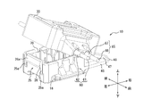
- FIG. 1 is a perspective view of the branch connector 10, the first cable 60, and the second cable 65 in a state where the insulating housing 15 according to the embodiment is in an unfolded state.
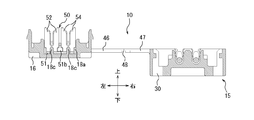
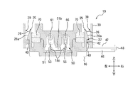
- 2 is a cross-sectional view taken along the line II of FIG.
- the branch connector 10 of this embodiment includes an insulating housing 15 and a relay contact 50 as large components.
- the insulating housing 15 is a molded product made of, for example, an insulating synthetic resin material.
- the insulating housing 15 integrally includes a first divided housing 16, a second divided housing 30, and a first connecting portion 46 and a second connecting portion 47 as a connecting portion that connects the first divided housing 16 and the second divided housing 30. Have been molded.
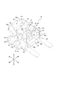
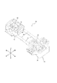
- FIG. 3 is an enlarged perspective view of only the first divided housing 16 in a state where the relay contact 50 is not provided.
- segmentation housing 16 is demonstrated in detail.
- the outer peripheral edge of one surface (the upper surface in FIG. 3) in the thickness direction of the first divided housing 16 is formed by the outer peripheral wall 17.
- the inner peripheral side of the outer peripheral wall 17 of the first divided housing 16 is constituted by an inner peripheral concave portion 17a that is recessed by one step from the upper surface of the first divided housing 16 (downward in FIG. 3).
- the bottom surface of the inner peripheral recess 17 a is configured by an inner peripheral first opposing surface 17 b that is a plane parallel to the upper surface of the first divided housing 16.
- the central portion located on the inner peripheral side from the inner peripheral first opposing surface 17b is constituted by a central first concave portion 17c that is recessed by one step from the inner peripheral first opposing surface 17b (downward in FIG. 3).
- the bottom surface of the central first concave portion 17c is constituted by a central first opposing surface 17d composed of a plane parallel to the inner peripheral first opposing surface 17b.
- a contact mounting groove 18 is formed by the central first recess 17c and the central first facing surface 17d.
- the contact mounting groove 18 has a fixed portion 18a and an intermediate convex portion 18b that is located in the middle in the left-right direction of the fixed portion 18a and narrows the front-back width of the fixed portion 18a to divide the fixed portion 18a into a pair of left and right.
- a substantially cylindrical positioning protrusion 18c is projected from the bottom surface (center first facing surface 17d) of the pair of fixing portions 18a.
- the outer peripheral wall 17 of the first divided housing 16 has a pair of first cable mounting grooves 19 located on both front and rear sides of one fixed portion 18a and on the same straight line, and on both front and rear sides of the other fixed portion 18a.
- a pair of second cable mounting grooves 20 that are positioned and collinear with each other (parallel to the first cable mounting groove 19) are recessed.
- the front shapes of the first cable mounting groove 19 and the second cable mounting groove 20 are semicircular.
- a pair of inclined surfaces 19 a that are inclined outward from the deepest bottom surface of the pair of first cable mounting grooves 19 are provided.
- a pair of inclined surfaces 20 a that are inclined outward from the deepest bottom surface of the pair of second cable attachment grooves 20 are provided.
- the front and rear surfaces of the outer peripheral wall 17 of the first divided housing 16 are provided with flat lid portions 21 and 22 that extend in the front-rear direction from a position below the front and rear inclined surfaces 19a and 20a.
- Opposing surfaces 21a and 22a (upper surfaces in FIG. 3) of the lid portions 21 and 22 are located at the same height as the lowermost portions of the inclined surfaces 19a and 20a.
- a pair of first lock portions 25 having elasticity are formed on the left and right side surfaces of the outer peripheral wall 17 of the first divided housing 16.
- a pair of concave portions 25 a is formed between each first lock portion 25 and the front and rear surfaces of the outer peripheral wall 17.
- Each first lock portion 25 has a first locking protrusion 26 that protrudes outward from the side surface of the first divided housing 16.
- the first locking projection 26 extends in the front-rear direction.
- Each of the first locking protrusions 26 has an inclined surface 26 a that is inclined outward from the first divided housing 16 as it goes downward.
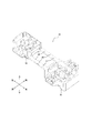
- FIG. 4 is an enlarged perspective view of only the second divided housing 30.
- the structure of the second divided housing 30 will be described in detail with reference to FIG.
- the outer peripheral wall 31 protrudes from the outer peripheral edge of one surface (the upper surface in FIG. 4) in the thickness direction of the second divided housing 30.
- a portion of the second divided housing 30 located on the inner peripheral side from the outer peripheral wall 31 is configured by an inner peripheral concave portion 31 a that is recessed by one step from the outer peripheral wall 31.
- the bottom surface of the inner circumferential recess 31 a is configured by an inner circumferential second opposing surface 31 b that is a plane parallel to the upper surface of the second divided housing 30.
- a cable pressing protrusion 32 having a pair of left and right U-shaped first pressing grooves 32a and a second pressing groove 32b protrudes from the inner peripheral second opposing surface 31b.
- the cable pressing protrusion 32 includes a central protrusion 32c and protrusions 32d and 32e formed on both left and right sides of the central protrusion 32c.
- a first pressing groove 32a is formed between the central protrusion 32c and one protrusion 32d.
- a second pressing groove 32b is formed between the central protrusion 32c and the other protrusion 32e.
- the second split housing 30 is formed with cable support arm portions 35 and 36 protruding from the front and rear surfaces.
- First cable holding grooves 35a and 36a and second cable holding grooves 35b and 36b are provided on the upper surfaces of the cable support arm portions 35 and 36, respectively.
- the front cable support arm portion 35 and the rear cable support arm portion 36 have a pair of projecting pieces 37a in which the front end side portion and the rear end side portion of the first cable holding grooves 35a and 36a are separated and divided into left and right by a gap. And a pair of protruding pieces 38a.
- the front cable support arm portion 35 and the rear cable support arm portion 36 have a pair of protruding pieces 37b in which the front end side portion and the rear end side portion of the second cable holding grooves 35b and 36b are separated and divided by a gap on the left and right. And a pair of protruding pieces 38b.
- Each of the pair of protruding pieces 37a, 38a, 37b, 38b, in particular, the left and right outer protruding pieces of the cable support arm portions 35, 36 are elastically bent in the left-right direction. Therefore, the interval between adjacent protruding pieces is variable.
- Each of the pair of projecting pieces 37a, 38a, 37b, and 38b has a claw portion that protrudes from the lower end portion of the front and rear end portions and faces each other.
- the first cable holding grooves 35a and 36a and the second cable holding grooves 35b and 36b are grooves having a depth for inserting and holding the first cable 60 and the second cable 65 over the entire diameter (the entire diameter can be accommodated). is there.
- the first cable holding grooves 35a and 36a have inclined surfaces 35e and 36e that are inclined upward toward the outside. That is, when the first cable 60 is inserted and held in the first cable holding grooves 35a and 36a, the first cable 60 is inclined by the inclined surfaces 35e and 36e of the first cable holding grooves 35a and 36a as shown in FIG. And incline in a diagonal direction at the corresponding cable portion.
- the second cable holding grooves 35b and 36b have inclined surfaces 35f and 36f.
- the second cable 65 is inserted and held in the second cable holding grooves 35 b and 36 b in the same manner as the first cable 60.
- a pair of drop-off prevention protrusions 35c and a pair of drop-out prevention protrusions 36c are provided near the upper opening portions of the front and rear ends of the first cable holding grooves 35a and 36a (the respective opposing surfaces of the protruding pieces 37a and 38a).
- a pair of drop-off prevention projections 35d and a pair of drop-off prevention projections 36d are provided near the upper openings (opposite surfaces of the protruding pieces 37b and 38b) of the front and rear ends of the second cable holding grooves 35b and 36b. It is done.
- the drop prevention protrusions 35c, 36c and 35d, 36d allow the first cable 60 and the second cable 65 to be inserted into the first cable holding grooves 35a, 36a and the second cable holding grooves 35b, 36b.
- the pair of projecting pieces 37a and 38a and the pair of projecting pieces 37b and 38b have an interval in the left-right direction (the distance between each pair of the drop-off prevention protrusions 35c and 36c and each pair of the drop-off prevention protrusions 35d and 36d). Bends to spread.
- each of the pair of protruding pieces 37a and 38a and each of the pair of protruding pieces 37b and 38b is elastically bent in a direction in which the distance between the left and right directions is narrowed. Accordingly, resistance is given to the first cable 60 and the second cable 65 inserted into the first cable holding grooves 35a and 36a and the second cable holding grooves 35b and 36b, and movement in the cable extension direction is allowed.
- each of the pair of protruding pieces 37a and 38a and each of the pair of protruding pieces 37b and 38b provides resistance to the force to be removed from the first cable holding grooves 35a and 36a and the second cable holding grooves 35b and 36b. Acts as a stopper to prevent it from coming off easily.
- each of the pair of protruding pieces 37a and 38a and each of the pair of protruding pieces 37b and 38b enables the first cable 60 and the second cable 65 to be detached by an external force of a certain level or more. The above-described retaining action is maintained even when the upper and lower sides (front and back) of the second divided housing 30 are reversed.
- a pair of second lock portions 39 are formed on the left and right side surfaces of the outer peripheral wall 31 of the second divided housing 30.
- the pair of second lock portions 39 is formed on the inner surface of the second divided housing 30.
- Each second lock portion 39 has a second locking projection 40 that protrudes inward from the side surface of the second divided housing 30.
- a pair of convex walls 41 extending in the vertical direction are formed at both front and rear ends of each second lock portion 39.
- Each of the second locking projections 40 has a substantially rectangular parallelepiped shape, and is formed above the inner surface of the second divided housing 30 so as to extend between the pair of convex walls 41. That is, the second locking protrusion 40 extends in the front-rear direction.
- a pair of hole portions 43 are formed on both left and right edges of the inner peripheral second opposing surface 31b so as to be adjacent to the second lock portions 39 on both left and right sides. Each hole 43 penetrates from the surface of the inner peripheral second opposing surface 31 b to the outer surface of the second divided housing 30.
- FIG. 5 is a perspective view showing the entire insulating housing 15 in a state where the relay contact 50 is not provided.
- the first divided housing 16 and the second divided housing 30 are a pair of front and rear first connection portions 46 linearly extending from the first divided housing 16 side, and a pair of front and rear first extending linearly from the second divided housing 30 side.
- the two connecting portions 47 are connected to each other by an easily bendable portion 48 that connects the first connecting portion 46 and the second connecting portion 47.
- the pair of front and rear first connection portions 46 and the pair of front and rear second connection portions 47 are located on the same plane in the deployed state.
- the bendable portion 48 is thinner than the front and rear first connection portions 46 and second connection portions 47.
- the front and rear first connection portions 46 and the second connection portion 47 are valley-folded (the first divided housing 16 and the second divided housing 30 in FIG. 1, FIG. 5, etc.) with the bendable portion 48 extending in the front-rear direction as a fold line. Can be folded in the direction of approaching (possible).
- the bending rigidity of the first connection portion 46 is set to be smaller than the bending rigidity of the second connection portion 47.
- the first divided housing 16, the first connection portion 46, the bendable portion 48, the second connection portion 47, and the second divided housing 30 autonomously maintain this expanded state in the expanded state shown in FIGS. Strength (rigidity)
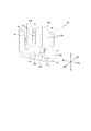
- FIG. 6 is a perspective view of the relay contact 50 alone. The structure of the relay contact 50 will be described in detail with reference to FIG.
- the relay contact 50 is obtained by forming a thin plate of a copper alloy having spring elasticity (for example, phosphor bronze, beryllium copper, or titanium copper) or a Corson copper alloy into a shape shown in the drawing using a progressive die (stamping). In the relay contact 50, after a base is formed on the surface by nickel plating, tin copper plating, tin plating, or gold plating is performed.
- a copper alloy having spring elasticity for example, phosphor bronze, beryllium copper, or titanium copper
- Corson copper alloy for example, phosphor bronze, beryllium copper, or titanium copper
- a progressive die stamping
- the relay contact 50 includes a flat plate-like base piece 51 extending in the left-right direction and a pair of flat plate-like shapes extending in a direction perpendicular to the base piece 51 and projecting from one end of both front and rear edges of the base piece 51.
- a first cable pressure contact piece 52, and a pair of flat second cable pressure contact pieces 54 that project from the other ends of the front and rear side edges of the base piece 51 and extend in a direction orthogonal to the base piece 51. are integrally provided.
- Circular positioning holes 51 a are formed at two positions on the left and right of the base piece 51.
- the first and second first and second cable pressure contact pieces 52 and 54 are respectively formed with a first pressure contact groove 53 and a second pressure contact groove 55 formed by a slit extending linearly toward the base piece 51 side. Is done.
- the upper end opening of the first pressure contact groove 53 is formed in a substantially V shape that widens upward by the tip 52a.
- the upper end opening of the second pressure contact groove 55 is formed in a substantially V shape that widens upward by the tip end portion 54a.
- the pair of front and rear first cable pressure contact pieces 52 and the pair of front and rear second cable pressure contact pieces 54 are connected to the base piece 51 via a narrow portion 52b and a narrow portion 54b, respectively.
- the distance between the opposed edge portions of the first cable pressure contact piece 52 and the second cable pressure contact piece 54 positioned in the left-right direction is narrower than the distance between the opposed edge portions of the narrow portion 52b and the narrow portion 54b.
- a play portion 51b is provided between the narrow portion 52b and the narrow portion 54b. No other member such as an insulator is interposed between the first cable pressure contact piece 52 and the second cable pressure contact piece 54.
- the relay contact 50 is included in a state in which the first divided housing 16 and the second divided housing 30 are in a conductive state with the first cable 60 and the second cable 65. More specifically, the relay contact 50 has an insulating covering 62 and a covering 67 by the first pressure contact groove 53 and the second pressure contact groove 55 when the first divided housing 16 and the second divided housing 30 are fitted.
- the first cable 60 and the second cable 65 are electrically connected to each other. That is, the relay contact 50 sandwiches the core wire 61 and the core wire 66 by the first press-contacting groove 53 and the second press-contacting groove 55, and electrically connects the first cable 60 and the second cable 65 to each other.
- the first cable 60 and the second cable 65 are tubular and flexible on the surfaces of core wires 61 and 66 (twisted wire or single wire) made of a conductive and flexible material (for example, copper or aluminum). And coverings 62 and 67 having electrical properties and insulating properties, respectively.
- the first cable 60 is a cable that is wired from the beginning inside a wiring object (for example, an automobile or the like) and connected to the power supply of the wiring object.
- the second cable 65 is a cable that is additionally connected to the first cable 60 later.
- An electronic device or an electric device (for example, a car navigation system) is connected to one end (front end) of the second cable 65.
- the filler 70 may be any material such as a waterproof gel, a UV curable resin, or an adhesive.
- the filler 70 will be described as an example of a UV curable resin having a waterproof function.
- FIG. 7 is a perspective view showing the branch connector 10 in which the filler 70 is loaded into the insulating housing 15 in the unfolded state.
- FIG. 8 is a perspective view showing a jig 80 for placing the insulating housing 15 before the filler 70 is loaded.
- a filler 70 is interposed between the inner peripheral first opposing surface 17 b of the first divided housing 16 and the inner peripheral second opposing surface 31 b of the second split housing 30.
- the surface shape of the filler 70 is formed in the first divided housing 16 and the second divided housing 30 so as to correspond to the respective inner surface shapes in a state where the first cable 60 and the second cable 65 are not placed. .
- the UV curable resin (filler 70) is a material that changes physical properties from a fluid state to an elastic state by irradiation with ultraviolet rays.
- the UV curable resin in the fluidized state is applied to the inner surfaces of the first divided housing 16 and the second divided housing 30 by a tool such as a dispenser. Since the UV curable resin has fluidity at this stage, the UV curable resin diffuses inside the first divided housing 16 and the second divided housing 30 so as to correspond to the inner surface shapes of the first divided housing 16 and the second divided housing 30.
- the surface shape of the UV curable resin is formed so as to correspond to the inner surface shapes of the first divided housing 16 and the second divided housing 30 in the flowing state. Thereafter, the UV curable resin changes its physical properties to an elastic state by irradiation with ultraviolet rays.
- the UV curable resin in a fluidized state is the second divided housing. Leak outside of 30. Therefore, a jig 80 is used to prevent resin leakage to the outside.
- the jig 80 has a first base 81 for placing the first divided housing 16 and a second base 82 for placing the second divided housing 30.
- the jig 80 is integrally formed so that the first base 81 and the second base 82 are continuous in the left-right direction.
- the vertical width of the first base 81 is larger than the vertical width of the second base 82.
- the jig 80 is formed such that the upper portion of the first base 81 protrudes upward from the upper surface of the second base 82.
- On the upper surface of the second base 82 a pair of protrusions 83 are formed that fit into the pair of holes 43 when the second divided housing 30 is placed.
- the vertical width between the upper surface of the first base 81 and the upper surface of the second base 82 matches the vertical width between the bottom surface of the first split housing 16 and the bottom surface of the second split housing 30. To do. That is, when the first divided housing 16 and the second divided housing 30 are placed on the jig 80, the pair of hole portions 43 of the second divided housing 30 are fitted with the pair of protrusions 83, and the first divided housing 16. And the bottom surface of the second divided housing 30 are in contact with the top surfaces of the first base 81 and the second base 82, respectively.
- the insulating housing 15 before being loaded with the UV curable resin is placed on the jig 80, and the pair of holes 43 of the second divided housing 30 are closed, and the UV is cured.
- the cured resin is applied.
- the surface shape of the UV curable resin corresponds to the shape of the upper surface of the protrusion 83 of the jig 80 in addition to the inner surface shape of the first divided housing 16 and the second divided housing 30 in the flowing state. It is formed.
- the filler 70 interposed in the inner peripheral first opposing surface 17b of the first divided housing 16 has the lower surface having a planar shape substantially the same as the inner peripheral first opposing surface 17b and surrounds the periphery of the relay contact 50. It is formed in a rectangular tube shape.
- the height of the filler 70 is a height at which the fillers 70 are in close contact with each other when the first divided housing 16 and the second divided housing 30 are closed.
- the filler 70 interposed on the inner peripheral second opposing surface 31 b of the second divided housing 30 has a lower surface having a planar shape substantially the same as the inner peripheral second opposing surface 31 b and surrounds the cable pressing protrusion 32. It is formed in a rectangular tube shape.
- the height of the filler 70 is a height at which the fillers 70 are in close contact with each other when the first divided housing 16 and the second divided housing 30 are closed.
- FIG. 9 is a perspective view of the branch connector 10, the first cable 60, and the second cable 65 when the insulating housing 15 transitions from the deployed state to the locked state.
- FIG. 10 is a perspective view of the branch connector 10, the first cable 60, and the second cable 65 when the insulating housing 15 is in a locked state.
- 11 is a cross-sectional view taken along the line II-II in FIG.
- the insulating housing 15, the relay contact 50, the first cable 60, the second cable 65, and the filler 70 are integrated, and the branch connector 10 is assembled while the first cable 60 and the second cable 65 are electrically connected.
- the assembly operator first fits the lower part of the relay contact 50 into the contact mounting groove 18 of the first divided housing 16 in the unfolded state shown in FIG. Specifically, the base piece 51 is fitted to the bottom of the contact mounting groove 18 while the play portion 51b is fitted to the intermediate convex portion 18b.
- the half part (the lower half part in FIGS. 1 and 2) of the first cable pressure contact piece 52 on the base piece 51 side is fitted to the corresponding fixing part 18a.
- the relay contact 50 is positioned with respect to the first divided housing 16.
- the front and rear first pressure contact grooves 53 are positioned on the axis passing through the front and rear first cable attachment grooves 19.
- the front and rear second pressure welding grooves 55 are positioned on the axis passing through the front and rear second cable mounting grooves 20.
- the assembly operator pushes against the resistance by the front and rear drop-off preventing projections 35c, 36c and 35d, 36d by hand or the like (see FIG. 1). At that time, each of the projecting pieces 37a, 38a, 37b, 38b bends against the elastic force and widens the gap between the anti-drop-off projections 35c, 36c and 35d, 36d.
- the first cable 60 and the second cable 65 are pushed into the first cable holding grooves 35a, 36a and the second cable holding grooves 35b, 36b, the gaps between the drop-off prevention protrusions 35c, 36c and 35d, 36d are narrowed.
- the first cable 60 and the second cable 65 are located between the bottoms of the first cable holding grooves 35a and 36a and the bottoms of the second cable holding grooves 35b and 36b and the drop-off preventing projections 35c, 36c and 35d, 36d. It is pinched. As a result, the first cable 60 and the second cable 65 are movable in the cable extension direction while receiving resistance. Therefore, it is possible to adjust the positions of the first cable 60 and the second cable 65 in the extending direction with respect to the branch connector 10 in the unfolded state shown in FIGS. The first cable 60 and the second cable 65 receive resistance that prevents the first cable holding grooves 35a and 36a and the second cable holding grooves 35b and 36b from being detached.
- the branch connector 10 is turned upside down, the first cable 60 and the second cable 65 do not easily fall out of the first cable holding grooves 35a and 36a and the second cable holding grooves 35b and 36b.
- the first cable 60 and the second cable 65 can be separated from the first cable holding grooves 35a and 36a and the second cable holding grooves 35b and 36b by an urging force of a certain level or more. Therefore, the replacement of the branch connector 10 and the change of the first cable 60 and the second cable 65 attached to and detached from the branch connector 10 are easy.
- the first cable 60 and the second cable 65 are arranged side by side in the left-right direction, with the first cable holding grooves 35a, 36a and the second cable holding grooves 35b, 36b fitted and held, with the front and rear bendable portions 48 as the center.
- the second divided housing 30 front and rear second connecting portions 47
- the second locking projection 40 on the first divided housing 16 side comes into contact with the inclined surface 26 a of the corresponding first locking projection 26.
- the corresponding first locking protrusion 26 is elastically deformed inward of the first divided housing 16 while the second locking protrusion 40 slides downward on the corresponding inclined surface 26a.
- the second pressing groove 32b of the cable pressing protrusion 32 located on the second connection portion 47 side slightly pushes the intermediate portion of the second cable 65 into the back side (downward) of the second pressure welding groove 55.
- the intermediate portion of the second cable 65 enters the space between the front and rear second cable pressure contact pieces 54.
- the cable pressing protrusion 32 When the second divided housing 30 is further rotated by a hand or the like in the direction approaching the first divided housing 16 around the front and rear bendable portions 48, the cable pressing protrusion 32 positioned on the opposite side to the second connection portion 47.
- the first pressing groove 32a presses the intermediate portion of the first cable 60 against the distal end portion 52a of the first cable pressing piece 52 in the extending direction of the first pressing groove 53 or a direction close thereto. Therefore, the first cable 60 is sandwiched between the distal end portion 52 a and the cable pressing protrusion 32.
- the first divided housing 16 and the second divided housing are used by a general tool (for example, a pliers) (not shown). 30 are pressed substantially parallel to the directions approaching each other. At this time, each second locking protrusion 40 engages with the corresponding first locking protrusion 26. Each convex wall 41 of the 2nd lock part 39 fits with the corresponding recessed part 25a.
- the first divided housing 16 is accommodated in the second divided housing 30, and the first lock portion 25 and the second lock portion 39 are located inside the fitted first divided housing 16 and second divided housing 30. Engage.
- the cable pressing protrusion 32 further pushes the intermediate portion of the first cable 60 and the second cable 65 into the back side (bottom side) of the first pressure contact groove 53 and the second pressure contact groove 55. Accordingly, the first cable 60 is pushed from the distal end portion 52 a to the substantially central portion of the first pressure contact groove 53, and the second cable 65 is pushed from the distal end portion 54 a to the substantially central portion of the second pressure contact groove 55. At this time, the pressing direction of the first cable 60 and the second cable 65 by the first pressing groove 32a and the second pressing groove 32b of the cable pressing protrusion 32 is the vertical direction (the first pressing groove 53 and the second pressing groove 55). Direction).
- both the left and right sides of the covering 62 of the first cable 60 are broken by the inner surface (left and right both sides) of the first pressure welding groove 53 and the second cable 65 is covered by the inner surface (left and right both sides) of the second pressure welding groove 55.
- the left and right sides of 67 are broken. Therefore, when the insulating housing 15 is held in the closed state, the inner surfaces (a pair of opposing surfaces) of the first pressure contact groove 53 are in uniform and reliable contact (pressure contact) with both sides of the core wire 61, and the first The inner surfaces (a pair of opposing surfaces) of the two pressure contact grooves 55 are in uniform and reliable contact (pressure contact) with both side portions of the core wire 66. That is, the core wire 61 of the first cable 60 and the core wire 66 of the second cable 65 are electrically connected to each other through the relay contact 50 inside the branch connector 10.
- the inner surfaces of the first press contact groove 53 and the second press contact groove 55 do not excessively hit against one of the both side portions of the core wires 61 and 66, a part of the core wires 61 and 66 is part of the first press contact groove. 53 and the second pressure contact groove 55 are not cut. Therefore, since the mechanical strength of the core wires 61 and 66 does not decrease, there is little possibility that the core wires 61 and 66 are completely cut even if a tensile force is applied to the first cable 60 and the second cable 65. Therefore, the contact reliability between the first cable 60 and the second cable 65 and the relay contact 50 can be improved.
- the facing surfaces 21a and 22a of the lid portions 21 and 22 of the first divided housing 16 are Part of the opening (the upper opening in FIG. 4) of the first cable holding grooves 35a and 36a and the second cable holding grooves 35b and 36b is blocked.
- the first cable 60 is sandwiched between the pair of inclined surfaces 19a of the first divided housing 16 and the corresponding inclined surfaces 35e and 36e of the second divided housing 30 from above and below.
- the second cable 65 is sandwiched between the pair of inclined surfaces 20 a of the first divided housing 16 and the corresponding inclined surfaces 35 f and 36 f of the second divided housing 30 from above and below.
- the relay contact 50 connects the first cable pressure contact piece 52 and the second cable pressure contact piece 54 and the base piece 51 by the narrow portions 52b and 54b.
- the gap (interval) between the first cable pressure contact piece 52 and the second cable pressure contact piece 54 is narrow, and an insulator or the like is not disposed in this gap. Therefore, the size of the relay contact 50, particularly the width in the left-right direction is reduced, and a reduction in size and weight is possible.
- the branch connector 10 When the branch connector 10 is shifted from the expanded state shown in FIG. 7 to the locked state, the entire interior of the fitted first divided housing 16 and second divided housing 30 is filled with the filler 70 as shown in FIG. . More specifically, when the first divided housing 16 and the second divided housing 30 are in a locked state, the filler 70 is applied to the inner peripheral first opposing surface 17b and the inner peripheral second opposing surface 31b. The periphery of the relay contact 50 is sealed tightly. The filler 70 surrounds the surfaces of the coverings 62 and 67 of the first cable 60 and the second cable 65 (without hindering electrical conduction with the relay contact 50).
- the first cable 60 and the second cable 65 extend outward from the relay contact 50 disposed inside the filler 70 in a locked state. That is, the first cable 60 and the second cable 65 extend outward from the pressure contact portion of the relay contact 50 along the front-rear direction.
- the filler 70 contacts the inner surfaces of the pair of first lock portions 25 of the first divided housing 16.
- the engaging surfaces 27 of the first locking projections 26 and the second locking projections 40 are configured to be positioned within the width of the filler 70 along the vertical direction in the vertical direction. Is preferred.
- the surface of the second locking projection 40 comes into contact with the outer surface of the first locking portion 25. It is preferable that the contact surface 42 formed thereby is substantially parallel to the inner surface of the first lock portion 25 that contacts the filler 70.
- the branch connector 10 does not need to be molded with the filler 70 as a separate member and is applied in a fluid state like a UV curable resin, the inner surface of the first divided housing 16 and the second divided housing 30 and the surface of the filler 70 are applied. It is difficult to form voids or air bubbles between the two. Since there is no direct contact with the filler 70 in the manufacturing process, there is no possibility that foreign matter adheres to the filler 70 or the shape of the filler 70 changes. Therefore, the branch connector 10 can make the filler 70 adhere to the inner surfaces of the first divided housing 16 and the second divided housing 30, and can improve waterproofness.
- the branch connector 10 can apply the filler 70 with a simple operation using a tool such as a dispenser, variation in assembly accuracy by the manufacturer can be suppressed. Since the branch connector 10 does not need to be molded with the filler 70 as a separate member, the number of man-hours can be reduced and the working time can be shortened.
- the branch connector 10 can be loaded with the filler 70 in accordance with various variations of the inner surface shape by using the corresponding jig 80.
- a UV curable resin as the filler 70, the resin can be changed to an elastic state only by irradiation with ultraviolet rays, so that the operation becomes simpler.
- the branch connector 10 can be loaded with the filler 70 corresponding to the internal shape of each product, and can maintain the waterproof property for each product.
- the filler 70 is in close contact with the first cable 60 and the second cable 65, even if the first cable 60 and the second cable 65 are bent and bent by an external force applied outside the branch connector 10, the first cable Transmission of movement or stress due to bending of the 60 and the second cable 65 to the pressure contact portion with the relay contact 50 is suppressed. Thereby, contact reliability is maintained.
- the branch connector 10 When the filler 70 comes into contact with the inner surface of the first lock portion 25, the first lock portion 25 having elasticity will be elastically deformed outward by an elastic force from the inside to the outside due to expansion or swelling of the filler 70. And since the branch connector 10 includes a lock portion on the inner side, the branch connector 10 can further strengthen the engagement between the first lock portion 25 and the second lock portion 39 by elastic deformation outward. More specifically, the engagement surface 27 of the first locking projection 26 and the second locking projection 40 is within the width in the vertical direction of the inner surface of the first lock portion 25 that contacts the filler 70, so The expansion force or the like of the agent 70 can be efficiently converted into the engagement force.
- the branch connector 10 can convert the expansion force or the like of the filler 70 into the engagement force more efficiently.
- the branch connector 10 can further enhance the close contact state between the first divided housing 16 and the second divided housing 30.
- the branch connector 10 can suppress the opening action of the first divided housing 16 and the second divided housing 30 even when the elastic force from the inside to the outside is applied.
- the branch connector 10 can maintain waterproofness. The effect appears even at room temperature, but becomes more prominent as the expansion of the filler 70 increases at higher temperatures.
- the branch connector 10 can further suppress the opening between the first divided housing 16 and the second divided housing 30. That is, the fillers 70 are arranged on both sides of the first divided housing 16 and the second divided housing 30 so that the respective fillers 70 adhere to each other in the locked state, and the first divided housing into which the adhesive force is fitted. 16 and the resistance against the opening of the second divided housing 30.
- the branch connector 10 has a locking mechanism formed inside the fitted first divided housing 16 and second divided housing 30, the outer peripheral wall 31 can be formed in a substantially planar shape with few irregularities or through holes. Thereby, the branch connector 10 can further improve waterproofness, and can further suppress entry of foreign matter such as dust and oil.
- the branch connector 10 is configured such that the first locking protrusion 26 extending in one direction and the second locking protrusion 40 extending in the same direction are engaged, and the engaging surface 27 extends in the same direction. By doing so, the area of the engagement surface 27 can be expanded and the engagement can be further strengthened.
- the engaging surface 27 is substantially horizontal as shown in FIG. 11, so that the engaging force is easily transmitted between the first locking protrusion 26 and the second locking protrusion 40.
- the jig 80 is described as being formed in a shape as shown in FIG. 8, but is not limited thereto.
- the jig 80 may have any shape as long as the shape corresponds to the shape of the insulating housing 15 and the filler 70 does not leak to the outside.
- FIG. 12 is an enlarged cross-sectional view corresponding to FIG. 11, in which the engaging portion between the first lock portion 25 and the second lock portion 39 according to another embodiment is enlarged.
- the engagement surfaces 27 of the first locking protrusions 26 and the second locking protrusions 40 are substantially horizontal planes extending in the front-rear direction, but are not limited thereto.
- the engagement surface 27 may be inclined downward from the inside to the outside of the fitted first divided housing 16 and the second divided housing 30.
- the branch connector 10 can further reduce the possibility of unlocking due to the cross-sectional shape.
- the first lock portion 25 is formed in the first divided housing 16 and the second lock portion 39 is formed in the second divided housing 30, but the present invention is not limited to this. Even if the first lock portion 25 having elasticity is formed on the second divided housing 30 side without the relay contact 50, the second lock portion 39 is formed on the first split housing 16 side having the relay contact 50. Good.
- the formation positions of the first lock portion 25 and the second lock portion 39 in the first split housing 16 and the second split housing 30 are not limited to the above, and the first split housing 16 and the second split housing 30 are fitted together. As long as it is possible to hold the lock, it may be in any formation position.
- first lock portion 25 and the second lock portion 39 have a first locking projection 26 and a second locking projection 40, respectively.
- the present invention is not limited to this.
- the 1st lock part 25 and the 2nd lock part 39 may have arbitrary locking means.
- the drop-off preventing projections 35c, 36c and 35d, 36d for preventing the first cable 60 and the second cable 65 from dropping are provided in the first cable holding grooves 35a, 36a and the second cable holding grooves 35b, 36b.
- the drop prevention protrusions may be provided in the first pressing groove 32a and the second pressing groove 32b of the cable pressing protrusion 32, respectively.
- the relay contact 50 is a type that presses the second cable 65, but may be a type that crimps the second cable 65.
- the second cable 65 is crimped to the relay contact 50 in advance, and the relay contact 50 is attached to the first divided housing 16 in this state.
- a cable crimping terminal is formed instead of one of the pair of first pressure contact grooves 53 and second pressure contact grooves 55 of the relay contact 50.
- the second split housing 30 is provided with one cable support arm portion 35 or 36 corresponding to the remaining pressure contact groove.
- three or more cables arranged in a direction orthogonal or substantially orthogonal to the extending direction of the portion supported by the branch connector 10 of each cable may be connected by the branch connector 10.
- three or more pairs of pressure contact grooves (aligned in the left-right direction) may be formed in one relay contact.
- a pressure contact groove may be formed in each of the plurality of relay contacts, and two or more pairs of pressure contact grooves may be formed in at least one relay contact, and the cable (core wire) may be pressure contacted by each pressure contact groove.
Landscapes
- Chemical & Material Sciences (AREA)
- Dispersion Chemistry (AREA)
- Connector Housings Or Holding Contact Members (AREA)
- Connections By Means Of Piercing Elements, Nuts, Or Screws (AREA)
- Manufacturing Of Electrical Connectors (AREA)
Abstract
L'invention concerne un connecteur de dérivation pouvant maintenir une propriété d'étanchéité à l'eau pour chaque unité dans laquelle une charge est chargée. Le connecteur de dérivation est pourvu : d'une paire de logements divisés (16, 30) qui peuvent être adaptés l'un sur l'autre et qui sont reliés par l'intermédiaire de parties de liaison (46, 47) ; et d'une charge (70) qui est chargée à l'intérieur de la paire de logements divisés (16, 30), la forme de surface de la charge (70) étant formée dans la paire de logements divisés (16, 30), correspondant aux formes de surface interne respectives de la paire de logements divisés (16, 30).
Priority Applications (4)
| Application Number | Priority Date | Filing Date | Title |
|---|---|---|---|
| CN201780029509.0A CN109155486B (zh) | 2016-05-25 | 2017-05-25 | 分支连接器 |
| US16/303,104 US10680352B2 (en) | 2016-05-25 | 2017-05-25 | Branch connector |
| JP2017541747A JP6550467B2 (ja) | 2016-05-25 | 2017-05-25 | 分岐コネクタ |
| EP17802899.9A EP3467955B1 (fr) | 2016-05-25 | 2017-05-25 | Connecteur de dérivation |
Applications Claiming Priority (2)
| Application Number | Priority Date | Filing Date | Title |
|---|---|---|---|
| JP2016104341 | 2016-05-25 | ||
| JP2016-104341 | 2016-05-25 |
Publications (1)
| Publication Number | Publication Date |
|---|---|
| WO2017204313A1 true WO2017204313A1 (fr) | 2017-11-30 |
Family
ID=60412872
Family Applications (1)
| Application Number | Title | Priority Date | Filing Date |
|---|---|---|---|
| PCT/JP2017/019626 Ceased WO2017204313A1 (fr) | 2016-05-25 | 2017-05-25 | Connecteur de dérivation |
Country Status (5)
| Country | Link |
|---|---|
| US (1) | US10680352B2 (fr) |
| EP (1) | EP3467955B1 (fr) |
| JP (1) | JP6550467B2 (fr) |
| CN (1) | CN109155486B (fr) |
| WO (1) | WO2017204313A1 (fr) |
Cited By (1)
| Publication number | Priority date | Publication date | Assignee | Title |
|---|---|---|---|---|
| JP2023180544A (ja) * | 2022-06-09 | 2023-12-21 | 澁谷工業株式会社 | ホログラフィ観察装置および試料保持容器 |
Families Citing this family (4)
| Publication number | Priority date | Publication date | Assignee | Title |
|---|---|---|---|---|
| JP6466983B2 (ja) * | 2017-03-22 | 2019-02-06 | 京セラ株式会社 | コネクタ |
| JP6466984B2 (ja) * | 2017-03-22 | 2019-02-06 | 京セラ株式会社 | コネクタ |
| JP6397962B1 (ja) * | 2017-05-24 | 2018-09-26 | 京セラ株式会社 | 梱包物 |
| JP6397965B1 (ja) * | 2017-06-19 | 2018-09-26 | 京セラ株式会社 | コネクタ |
Citations (6)
| Publication number | Priority date | Publication date | Assignee | Title |
|---|---|---|---|---|
| JPH04111110U (ja) * | 1991-03-14 | 1992-09-28 | 古河電気工業株式会社 | 自動車用電線の接続部 |
| JPH0664366U (ja) * | 1993-02-18 | 1994-09-09 | 日本エー・エム・ピー株式会社 | 圧接型コネクタ |
| JP3028988B2 (ja) | 1992-02-05 | 2000-04-04 | トヨタ自動車株式会社 | コネクタ |
| JP2605275Y2 (ja) | 1993-12-27 | 2000-07-04 | 京セラエルコ株式会社 | 電気コネクタのケーブル保護装置 |
| JP2006294486A (ja) * | 2005-04-13 | 2006-10-26 | Hitachi Mobile Co Ltd | 電線分岐端子および電線分岐方法 |
| JP2015060814A (ja) * | 2013-09-20 | 2015-03-30 | ホシデン株式会社 | コネクタ |
Family Cites Families (18)
| Publication number | Priority date | Publication date | Assignee | Title |
|---|---|---|---|---|
| GB9103902D0 (en) * | 1991-02-25 | 1991-04-10 | Raychem Sa Nv | Electrically-protected connector |
| US5147217A (en) * | 1991-06-18 | 1992-09-15 | General Motors Corporation | Electrical component package |
| JPH069065U (ja) * | 1992-07-06 | 1994-02-04 | 本田技研工業株式会社 | ワイヤハーネスの防水ジョイント構造 |
| JP3066713B2 (ja) * | 1995-02-09 | 2000-07-17 | 矢崎総業株式会社 | 圧接ジョイントコネクタ |
| JP3097819B2 (ja) * | 1995-07-04 | 2000-10-10 | 矢崎総業株式会社 | 圧接ジョイントコネクタ及びそれを用いたワイヤーハーネスの組立て方法 |
| JP3636393B2 (ja) * | 1995-10-31 | 2005-04-06 | ミネソタ マイニング アンド マニュファクチャリング カンパニー | 分岐コネクタ装置 |
| WO1998033241A1 (fr) * | 1997-01-28 | 1998-07-30 | The Whitaker Corporation | Joint etanche pour connecteur electrique, procede de fabrication d'un tel joint et utilisation d'un tel joint |
| JP3408391B2 (ja) * | 1997-04-02 | 2003-05-19 | 矢崎総業株式会社 | コネクタ |
| JP2000515677A (ja) * | 1997-05-22 | 2000-11-21 | トーマス アンド ベッツ インターナショナル,インク. | ケーブル・スプライス・クロージャ |
| DE19741603A1 (de) * | 1997-09-20 | 1999-03-25 | Volkswagen Ag | Elektrische Kontakteinrichtung sowie Verfahren zur Schneidkontaktherstellung |
| DE10142363A1 (de) * | 2001-08-30 | 2003-03-27 | Delphi Tech Inc | Elektrischer Verbinder |
| JP3889983B2 (ja) * | 2002-03-20 | 2007-03-07 | 矢崎総業株式会社 | コネクタ |
| US7384297B2 (en) * | 2006-11-07 | 2008-06-10 | King Jr Lloyd Herbert | Wire connector |
| US7686661B2 (en) * | 2008-07-31 | 2010-03-30 | Tyco Electronics Corporation | Connection enclosure assemblies, connector systems and methods for forming an enclosed connection between conductors |
| US7833038B1 (en) * | 2009-04-08 | 2010-11-16 | King Jr Lloyd Herbert | Inline push-in wire connectors |
| CN103066547A (zh) * | 2011-10-18 | 2013-04-24 | 上海市高桥电缆厂有限公司 | 电缆分支连接器 |
| US8967888B2 (en) * | 2012-04-25 | 2015-03-03 | Tyco Electronics Raychem Bvba | Dry silicone gels and their methods of making using thiol-ene chemistry |
| US20150171543A1 (en) * | 2013-12-13 | 2015-06-18 | General Electric Company | Sealed electrical connector assembly |
-
2017
- 2017-05-25 CN CN201780029509.0A patent/CN109155486B/zh active Active
- 2017-05-25 JP JP2017541747A patent/JP6550467B2/ja active Active
- 2017-05-25 US US16/303,104 patent/US10680352B2/en active Active
- 2017-05-25 WO PCT/JP2017/019626 patent/WO2017204313A1/fr not_active Ceased
- 2017-05-25 EP EP17802899.9A patent/EP3467955B1/fr active Active
Patent Citations (6)
| Publication number | Priority date | Publication date | Assignee | Title |
|---|---|---|---|---|
| JPH04111110U (ja) * | 1991-03-14 | 1992-09-28 | 古河電気工業株式会社 | 自動車用電線の接続部 |
| JP3028988B2 (ja) | 1992-02-05 | 2000-04-04 | トヨタ自動車株式会社 | コネクタ |
| JPH0664366U (ja) * | 1993-02-18 | 1994-09-09 | 日本エー・エム・ピー株式会社 | 圧接型コネクタ |
| JP2605275Y2 (ja) | 1993-12-27 | 2000-07-04 | 京セラエルコ株式会社 | 電気コネクタのケーブル保護装置 |
| JP2006294486A (ja) * | 2005-04-13 | 2006-10-26 | Hitachi Mobile Co Ltd | 電線分岐端子および電線分岐方法 |
| JP2015060814A (ja) * | 2013-09-20 | 2015-03-30 | ホシデン株式会社 | コネクタ |
Non-Patent Citations (1)
| Title |
|---|
| See also references of EP3467955A4 |
Cited By (1)
| Publication number | Priority date | Publication date | Assignee | Title |
|---|---|---|---|---|
| JP2023180544A (ja) * | 2022-06-09 | 2023-12-21 | 澁谷工業株式会社 | ホログラフィ観察装置および試料保持容器 |
Also Published As
| Publication number | Publication date |
|---|---|
| EP3467955A4 (fr) | 2020-01-01 |
| JP6550467B2 (ja) | 2019-07-24 |
| CN109155486B (zh) | 2020-06-05 |
| US20190319372A1 (en) | 2019-10-17 |
| CN109155486A (zh) | 2019-01-04 |
| EP3467955B1 (fr) | 2024-07-17 |
| JPWO2017204313A1 (ja) | 2018-06-07 |
| EP3467955A1 (fr) | 2019-04-10 |
| US10680352B2 (en) | 2020-06-09 |
Similar Documents
| Publication | Publication Date | Title |
|---|---|---|
| JP6397864B2 (ja) | 分岐コネクタ | |
| JP6397965B1 (ja) | コネクタ | |
| JP6495216B2 (ja) | 分岐コネクタ | |
| WO2017204313A1 (fr) | Connecteur de dérivation | |
| JP6486419B2 (ja) | コネクタ | |
| JP6466984B2 (ja) | コネクタ | |
| JP6401869B1 (ja) | コネクタ | |
| JP6466983B2 (ja) | コネクタ | |
| JP6598810B2 (ja) | コネクタ | |
| JP6401770B2 (ja) | 分岐コネクタ | |
| WO2018173685A1 (fr) | Connecteur | |
| JP2018160457A (ja) | コネクタ |
Legal Events
| Date | Code | Title | Description |
|---|---|---|---|
| ENP | Entry into the national phase |
Ref document number: 2017541747 Country of ref document: JP Kind code of ref document: A |
|
| NENP | Non-entry into the national phase |
Ref country code: DE |
|
| 121 | Ep: the epo has been informed by wipo that ep was designated in this application |
Ref document number: 17802899 Country of ref document: EP Kind code of ref document: A1 |
|
| ENP | Entry into the national phase |
Ref document number: 2017802899 Country of ref document: EP Effective date: 20190102 |