WO2017204341A1 - Commutateur à bouton-poussoir - Google Patents
Commutateur à bouton-poussoir Download PDFInfo
- Publication number
- WO2017204341A1 WO2017204341A1 PCT/JP2017/019761 JP2017019761W WO2017204341A1 WO 2017204341 A1 WO2017204341 A1 WO 2017204341A1 JP 2017019761 W JP2017019761 W JP 2017019761W WO 2017204341 A1 WO2017204341 A1 WO 2017204341A1
- Authority
- WO
- WIPO (PCT)
- Prior art keywords
- pusher
- main body
- contact
- plunger
- skirt
- Prior art date
- Legal status (The legal status is an assumption and is not a legal conclusion. Google has not performed a legal analysis and makes no representation as to the accuracy of the status listed.)
- Ceased
Links
Images




Classifications
-
- H—ELECTRICITY
- H01—ELECTRIC ELEMENTS
- H01H—ELECTRIC SWITCHES; RELAYS; SELECTORS; EMERGENCY PROTECTIVE DEVICES
- H01H13/00—Switches having rectilinearly-movable operating part or parts adapted for pushing or pulling in one direction only, e.g. push-button switch
- H01H13/50—Switches having rectilinearly-movable operating part or parts adapted for pushing or pulling in one direction only, e.g. push-button switch having a single operating member
- H01H13/64—Switches having rectilinearly-movable operating part or parts adapted for pushing or pulling in one direction only, e.g. push-button switch having a single operating member wherein the switch has more than two electrically distinguishable positions, e.g. multi-position push-button switches
-
- H—ELECTRICITY
- H01—ELECTRIC ELEMENTS
- H01H—ELECTRIC SWITCHES; RELAYS; SELECTORS; EMERGENCY PROTECTIVE DEVICES
- H01H13/00—Switches having rectilinearly-movable operating part or parts adapted for pushing or pulling in one direction only, e.g. push-button switch
- H01H13/50—Switches having rectilinearly-movable operating part or parts adapted for pushing or pulling in one direction only, e.g. push-button switch having a single operating member
- H01H13/64—Switches having rectilinearly-movable operating part or parts adapted for pushing or pulling in one direction only, e.g. push-button switch having a single operating member wherein the switch has more than two electrically distinguishable positions, e.g. multi-position push-button switches
- H01H13/66—Switches having rectilinearly-movable operating part or parts adapted for pushing or pulling in one direction only, e.g. push-button switch having a single operating member wherein the switch has more than two electrically distinguishable positions, e.g. multi-position push-button switches the operating member having only two positions
-
- H—ELECTRICITY
- H01—ELECTRIC ELEMENTS
- H01H—ELECTRIC SWITCHES; RELAYS; SELECTORS; EMERGENCY PROTECTIVE DEVICES
- H01H2209/00—Layers
- H01H2209/004—Depressions or protrusions on switch sites
-
- H—ELECTRICITY
- H01—ELECTRIC ELEMENTS
- H01H—ELECTRIC SWITCHES; RELAYS; SELECTORS; EMERGENCY PROTECTIVE DEVICES
- H01H2209/00—Layers
- H01H2209/068—Properties of the membrane
- H01H2209/074—Properties of the membrane elastomeric
-
- H—ELECTRICITY
- H01—ELECTRIC ELEMENTS
- H01H—ELECTRIC SWITCHES; RELAYS; SELECTORS; EMERGENCY PROTECTIVE DEVICES
- H01H2215/00—Tactile feedback
- H01H2215/004—Collapsible dome or bubble
- H01H2215/008—Part of substrate or membrane
-
- H—ELECTRICITY
- H01—ELECTRIC ELEMENTS
- H01H—ELECTRIC SWITCHES; RELAYS; SELECTORS; EMERGENCY PROTECTIVE DEVICES
- H01H2225/00—Switch site location
- H01H2225/018—Consecutive operations
-
- H—ELECTRICITY
- H01—ELECTRIC ELEMENTS
- H01H—ELECTRIC SWITCHES; RELAYS; SELECTORS; EMERGENCY PROTECTIVE DEVICES
- H01H2235/00—Springs
- H01H2235/008—Rubber spring
Definitions
- the present invention relates to a push button switch for input operation incorporated in an electric device for home use, in-vehicle use, and portable use, and particularly relates to a push button switch capable of performing two-stage input by one continuous push operation. is there.
- the push button switch is used to turn on and off the circuit by pressing a pressing operation unit and a movable contact provided on the pusher side comes into contact with a circuit contact provided on the circuit board side.
- a click feeling generated by buckling of the skirt portion elastically supporting the pusher is transmitted to the operator's finger, and an operation feeling can be obtained.
- Patent Document 1 discloses a pushbutton switch that operates a plurality of switch operating units arranged in parallel on the same plane by pressing one key knob as a pressing operation unit.
- a first switch operating unit and a second switch operating unit higher than the first switch operating unit are provided.
- the key knob is depressed, first, the skirt portion of the second switch operating portion that is in contact with the key knob is buckled, and the movable contact provided in the second switch operating portion comes into contact with the fixed contact of the circuit board.
- the lower surface of the key knob that contacts the first switch operating portion and the second switch operating portion is formed as a wide and flat surface. Therefore, the skirt portion of the second switch actuating portion that is buckled and curved upward as the key knob is pressed comes into contact with the lower surface of the key knob, making it difficult to press the key knob and making it difficult to obtain a desired click feeling. There was a problem.
- the present invention has been made in view of the above-described problems, and is a push button switch capable of performing two-stage input, and prevents the pressing operation unit from interfering with other configurations when the pressing operation unit is pressed.
- An object of the present invention is to provide a push button switch that can perform a smooth input operation and obtain a desired click feeling.
- the present invention relates to a pushbutton switch that is in conductive contact with a circuit contact of a circuit board, and includes a base, a first pusher protruding from the base, and a second pusher formed away from the first pusher.
- An operation part a first main body part formed at a position facing the first pusher part, and a rubber-like elastic body that is continuous with the lower peripheral edge of the first main body part and elastically supports the first main body part.
- a cylindrical rubber having a first skirt portion, a first operating portion having a first movable contact provided at a lower portion of the first main body portion, and a cavity formed in a position facing the second pusher portion.
- a second main body portion made of a rubber-like elastic body, a second skirt portion made of a rubber-like elastic body that continues to the lower peripheral edge of the second main body portion and elastically supports the second main body portion, and a lower portion of the second main body portion
- a second actuating part having a second movable contact provided on the second pressing part, wherein the second pusher part contacts the second body part
- the first pusher portion is formed apart from the second pusher portion, the first skirt portion and the second skirt portion that are buckled and curved upward are accommodated in the separation portion, and these are the pressing operation portion. Will not abut. Therefore, the pressing operation unit can be pressed smoothly.
- the pressing resistance of the pressing operation portion changes between the first-stage operation and the second-stage operation, so that different click feelings can be obtained between the first-stage operation and the second-stage operation.
- the first pusher portion can be formed lower than the second pusher portion.
- the first pusher portion By forming the first pusher portion lower than the second pusher portion, it is possible to secure a wide accommodation space for the first actuating portion. Therefore, the first skirt portion of the first operating portion can be formed high and can be easily buckled, and the first operating portion can be easily pressed down.
- the first body portion can be formed lower than the second body portion.
- the first main body portion By forming the first main body portion lower than the second main body portion, it is possible to secure a large storage space for the first operation portion, so that the first skirt portion of the first operation portion is formed high and easily buckled. It is possible to make it easier to press the first operating part.
- the second skirt portion can be formed thinner than the second main body portion.
- the second skirt part By forming the second skirt part thinner than the second body part, it is possible to buckle only the second skirt part in the first stage operation, and the second body part is compressed in the second stage operation. Can be made. As a result, the pressing resistance of the pressing operation portion changes between the first-stage operation and the second-stage operation, so that different click feelings can be obtained between the first-stage operation and the second-stage operation.
- a notch can be provided at the tip of the second body.
- a groove can be provided at the tip of the second pusher.
- Providing a groove at the tip of the second pusher part also makes it easier for air in the second main body part to escape when the second main body part is pushed down by the second pusher part, compressing the second main body part. It can be made easier.
- a protrusion can be provided at the tip of the second pusher.
- the pressing operation unit when the pressing operation unit is pressed, the pressing operation unit can be smoothly pressed without interfering with other components, and a desired click feeling can be obtained. Therefore, the usability of the electronic device equipped with the pushbutton switch according to the present invention can be improved, and an erroneous operation when the user of the electronic device performs two-stage input can be prevented.
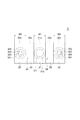
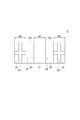
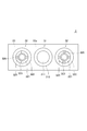
- the exploded sectional view showing the pushbutton switch by a 1st embodiment of the present invention The bottom view which shows the plunger of the pushbutton switch of FIG.
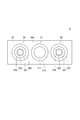
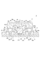
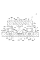
- the top view which shows the switch action body of the pushbutton switch of FIG. Sectional drawing which shows the initial state of the pushbutton switch of FIG. Sectional drawing which shows the state which pushed in the plunger from the state of FIG. Sectional drawing which shows the state which pushed in the plunger further from the state of FIG. Sectional drawing which shows the state which pushed in the plunger further from the state of FIG. Sectional drawing which shows the state which pushed in the plunger further from the state of FIG. Sectional drawing which shows the pushbutton switch by 2nd Embodiment.
- the bottom view which shows the plunger of the pushbutton switch by the 1st modification.
- the top view which shows the switch action body of the pushbutton switch by the 2nd modification.
- the pushbutton switch 1 is a pushbutton switch 1 that is in conductive contact with a circuit contact of a circuit board, and includes a plunger 2 that serves as a “pressing operation portion” and a switch operating body 3 that is provided below the plunger 2. This is a push button switch 1 that can be operated in two steps.
- the plunger 2 has a long plate-like base 23, a first pusher portion 21 protruding from the longitudinal center of the base 23, and 2 protruding higher than the first pusher portion 21 from both longitudinal ends of the base 23. Two second pusher portions 22 are provided. An upper surface 23b of the plunger 2 serves as an operation surface of the push button switch 1.
- the material of the plunger 2 can be suitably used as long as the material has a hardness capable of pressing the switch operating body 3 such as hard resin, metal, wood, or the like.
- the first pusher portion 21 has a configuration protruding in a rectangular shape from the vicinity of the center of the bottom surface 23a of the base portion 23 in the longitudinal direction.
- the width W1 in the short direction (longitudinal direction of the plunger 2) of the first pusher portion 21 is formed to be equal to or larger than the diameter of the first operating portion 31 described later. Thereby, when the plunger 2 is pressed down, the 1st action
- the lower surface of the first pusher portion 21 serves as a contact surface 21 a with the first operating portion 31.
- the second pusher portion 22 is configured to protrude in a rectangular shape from both ends in the longitudinal direction of the plunger 2 on the bottom surface 23 a of the base portion 23.
- the first pusher portion 21 and the second pusher portion 22 are formed to be separated by a groove portion 24. Therefore, even when a first skirt portion 312 and a second skirt portion 322 which will be described later are buckled and bent upward in an arch shape, even when the bent portion reaches a height exceeding the upper end of the second pusher portion 22.
- By accommodating the bent portion in the separated portion it is possible to prevent the plunger 2 and the bent portion from coming into contact with each other and preventing the plunger 2 from being pressed.
- the width W2 in the short direction (longitudinal direction of the plunger 2) of the second pusher portion 22 is formed to be equal to or larger than the diameter of the second operating portion 32 described later. Thereby, when the plunger 2 is pressed, the second operating part 32 can be surely pressed.
- the width W2 of the second pusher portion 22 is larger than the diameter of the second operating portion 32, the second main body deformed when the second main body portion 321 of the second operating portion 32 is compressed as will be described later. It is preferable because the problem that the portion 321 is covered and locked on the second pusher portion 22 and the plunger 2 is prevented from returning to the initial position can be prevented.
- the lower surface of the second pusher portion 22 serves as a contact surface 22 a with the second operating portion 32.
- the switch actuating body 3 is made of a rubber-like elastic body, and includes a long plate-like base portion 33 and a first actuating portion 31 that protrudes to a position facing the first pusher portion 21 on the upper surface side of the base portion 33. , And two second actuating portions 32 that are formed to protrude to a position facing the second pusher portion 22 on the upper surface side of the base portion 33.
- TPE synthetic rubber and thermoplastic elastomer
- silicone rubber specifically, silicone rubber, urethane rubber, fluorine rubber, nitrile rubber, ethylene propylene rubber, styrene TPE, olefin TPE, urethane TPE, Polyester TPE or the like can be used.
- silicone rubber is a preferable material because it hardly changes in hardness even at low or high temperatures, has durability, and has a small compression set.
- the base portion 33 is a long plate-like member, and a first operating portion 31 and two second operating portions 32 are formed in a line so as to protrude from the upper surface 33a.
- the first actuating portion 31 includes a first main body portion 311 formed at a position facing the first pusher portion 21, a first skirt portion 312 continuous with a lower peripheral edge portion of the first main body portion 311, and a first A first movable contact 314 provided at the lower part of the main body 311 is provided.
- the first main body portion 311 is elastically supported by the first skirt portion 312 with respect to the base portion 33, and has a dense cylindrical configuration inside.
- a pressing portion 313 is formed in a cylindrical shape at a lower portion of the first main body portion 311, and a first movable contact 314 is formed at a tip portion of the pressing portion 313.
- the first skirt portion 312 rises in a truncated cone shape from the base portion 33 and is formed thinner than the base portion 33.
- the first skirt portion 312 elastically supports the first main body portion 311 with respect to the base portion 33.
- the first movable contact 314 is a conductive member, and a conductive contact is formed by providing a conductive coating film, a metal plate, a metal thin wire, or the like on the lower surface of the first main body 311.
- the second actuating part 32 includes a second main body part 321 formed at a position facing the second pusher part 22, a second skirt part 322 continuing to the lower peripheral edge part of the second main body part 321, and a second A second movable contact 324 provided on the lower side of the main body 321 is provided.
- Two second operating parts 32 are provided around the first operating part 31, and the first operating part 31 and the two second operating parts 32 are in a line.
- the second main body portion 321 has a cylindrical configuration having a cavity 321a therein that is elastically supported by the second skirt portion 322 with respect to the base portion 33.
- a dense cylindrical pressing portion 323 that is continuous with the second main body portion 321 is formed at a lower portion of the second main body portion 321 via a thin connecting portion 325, and a second movable portion is provided at a tip portion of the pressing portion 323.
- a contact 324 is formed.
- the height of the second main body portion 321 is the same as the height of the first main body portion 311.
- the second skirt portion 322 rises in a truncated cone shape from the base portion 33 and is formed thinner than the base portion 33 and the second main body portion 321.
- the second skirt portion 322 elastically supports the second main body portion 321 with respect to the base portion 33.
- the second movable contact 324 is a conductive member, and a conductive contact is formed by providing a conductive coating film, a metal plate, a thin metal wire, or the like on the lower surface of the pressing portion 323.
- the plunger 2 does not tilt when the plunger 2 is pressed, and it is easy to press vertically.
- Circuit board [ Figure 1]
- a first circuit contact 42 is formed at a position facing the first movable contact 314 on the surface of the substrate body 41, and a second circuit contact 43 is disposed at a position facing the two second movable contacts 324, respectively.
- the first circuit contact 42 and the two second circuit contacts 43 are arranged in a line.
- the substrate body 41 has a rolled copper foil attached to a flexible circuit board based on a polyethylene terephthalate film, a polyethylene naphthalate film, a polyimide film, or a rigid circuit board based on a glass epoxy or glass composite base material.
- the copper foil is etched so as to have a desired circuit pattern.
- the first circuit contact 42 and the second circuit contact 43 are made of conductive metal, and are formed in a contact shape in which comb-like patterns face each other or in a contact shape provided concentrically.
- a protective layer such as a gold plating film or a conductive layer made of carbon ink is provided.
- the distance B between the first circuit contact 42 and the first movable contact 314 is shorter than the distance A1 between the second circuit contact 43 and the second movable contact 324. Since the distance B1 is shorter than the distance A1, the pressing distance of the plunger 2 in the second stage operation in which the pressing resistance of the plunger 2 is increased as compared with the first stage operation can be shortened. Can reduce the operation burden.
- the distance A1 between the second circuit contact 43 and the second movable contact 324 is equal to the height difference A2 between the first pusher portion 21 and the second pusher portion 22.
- FIG. 1 shows a state where the plunger 2 and the switch operating body 3 are separated from each other.
- the actual first stage operation is the second pusher portion of the plunger 2 as shown in FIG. 22 starts from a state in which the second main body portion 321 of the second operating portion 32 abuts. That is, the initial state of the pushbutton switch 1 is the state shown in FIG.
- the distance between the second movable contact 324 and the second circuit contact 43 is A1
- the distance between the contact surface 21a of the first pusher portion 21 and the upper surface of the first body portion 311 is A2, which is equal to A1
- the distance between the first movable contact 314 and the first circuit contact 42 is B shorter than A1.
- the buckled second skirt portion 322 is curved upward as the plunger 2 is pressed. However, since the groove portion 24 is formed in the plunger 2, the curved second skirt portion 322 is formed by the groove portion 24. The second skirt portion 322 is prevented from coming into contact with the plunger 2. This prevents the curved second skirt portion 322 from coming into contact with the plunger 2 and prevents the plunger 2 from being prevented from being pressed, and the plunger 2 can be smoothly pressed down during the first stage operation and the second stage operation described below. Can do.
- the second movable contact 324 provided below the second main body 321 eventually comes into contact with the second circuit contact 43 of the circuit board 4 as shown in FIG. Becomes electrically conductive.
- the first pusher portion 21 is also pushed by the distance A2 that is equal to the distance A1. Therefore, the first pusher portion 21 comes into contact with the first main body portion 311. Thus, the first stage operation is completed.
- the second stage operation is started.
- the plunger 2 is further pressed from the state of FIG. 6, the second main body portion 321 of the second operating portion 32 is compressed, and the first skirt portion 312 and the connecting portion 325 of the first operating portion 31 are buckled, The first main body 311 that is in contact with the first pusher 21 is pressed.
- the user can obtain a click feeling due to buckling of the first skirt portion 312 and the connecting portion 325.
- the buckled first skirt portion 312 is curved upward as the plunger 2 is pressed, but since the groove portion 24 is formed in the plunger 2, the curved first skirt portion is caused by the groove portion 24. It is accommodated in the space to be formed, and the contact of the first skirt portion 312 with the plunger 2 is prevented. This prevents the curved first skirt portion 312 from coming into contact with the plunger 2 and prevents the plunger 2 from being prevented from being depressed, and the plunger 2 can be smoothly depressed even in the second stage operation.
- the resistance to pressing in the second-stage operation is greater than the resistance to pressing in the first stage.
- the resistance to the first stage operation is caused only by the buckling resistance of the second skirt part 322, while the resistance to the second stage operation is thicker and more resistant than the second skirt part 322.
- the buckling resistance of the first skirt portion 312 and the connecting portion 325 is further added to the compression resistance.
- the pressing resistance during the second stage operation can be made larger than the pressing resistance during the first stage operation, and the user can distinguish between the first stage operation and the second stage operation according to the operational feeling. can do.
- the buckled connecting portion 325 has an effect of continuously pressing the second movable contact 324 against the second circuit contact 43 during the second stage operation due to its elastic restoring force. Thereby, it is possible to prevent the conductive contact between the second movable contact 324 and the second circuit contact 43 from being released during the second stage operation.
- the contact between the first movable contact 314 and the first circuit contact 42 further increases the resistance against pressing of the plunger 2, and the user can sense that the second stage operation has been completed. .
- the groove portion 24 is formed between the first pusher portion 21 and the second pusher portion 22 of the plunger 2. Accordingly, the first skirt portion 312 and the second skirt portion 322 that are buckled and curved upward are accommodated in the space formed by the groove portion 24 and are prevented from coming into contact with the lower surface of the plunger 2.
- the lower surface of the plunger 2 to be pressed is prevented from coming into contact with the first skirt portion 312 or the second skirt portion 322 which is curved upward, and the pressing of the plunger 2 is prevented from being prevented. In any of these operations, the plunger 2 can be smoothly pressed.
- first pusher portion 21 is formed lower than the second pusher portion 22 with respect to the base portion 23, a wide space can be secured below the first pusher portion 21. Therefore, a large accommodation space for the first operating portion 31 can be secured, and the first main body portion 311 and the first skirt portion 312 of the first operating portion 31 can be formed high.
- the first operating portion 31 can be easily pushed in in the second stage operation.
- Pushbutton switch according to the second embodiment [FIG. 8]
- the height of the first skirt portion 312 of the first operating portion 31 is secured by forming the first pusher portion 21 lower than the second pusher portion 22.
- One skirt portion 312 was easily buckled.
- the present invention is not limited to this, and as shown in FIG. 8, the height of the first skirt portion 312 is not changed, the height of the first main body portion 311 ′ is formed low, and the first pusher portion 21 ′ is formed. May be the same as the height of the second pusher portion 22. In FIG. 8, the same components as those in FIG.
- the push button switch 1 ′ having such a configuration can achieve the same effects as the push button switch 1 according to the first embodiment described above, and the first pusher portion 21 ′ and the second pusher portion 22 for the plunger 2 ′. Therefore, the plunger 2 'can be designed more easily.
- a cross-shaped groove 221 for escaping air may be formed at the tip of the second pusher portion 22 of the plunger 2.
- the shape of the groove part 221 is not restricted to a cross shape, it can prevent that the pressing force with respect to the 2nd main-body part 321 is biased by having a cross shape.
- a cross-shaped protrusion may be formed.
- the effect similar to the cross-shaped groove part 221 can be show
- a notch portion 326 may be formed at the distal end portion of the second main body portion 321 of the second operating portion 32.
- the air in the second main body portion 321 can be easily removed and the second main body portion 321 can be easily compressed.
- the cutout portion 326 having the same shape in four directions, it is possible to prevent the pressing force on the second main body portion 321 from being biased. Even if such a notch 326 is formed, the shape of the second main body 321 is assumed to be cylindrical.
- the two second operation parts 32 are provided.
- the number is not limited to two, and one or three or more second operation parts 32 may be provided. Good.
- the number of second pusher portions 22 of the plunger 2 is increased or decreased in accordance with the number of second actuating portions 32.
- the first operating unit 31 and the second operating unit 32 accumulate in a space surrounded by the circuit board 4. It is preferable to provide a configuration that allows air to escape. Therefore, for example, a vent hole or an air groove that allows air to escape may be formed in the base portion 33 or the substrate body 41.
- the first operating part 31 and the two second operating parts 32 are arranged side by side in a straight line.
- the present invention is not limited to this and can be arbitrarily arranged. .
- the base 23 of the plungers 2 and 2 ′ has a long plate shape.
- the present invention is not limited to this, and an arbitrary shape such as a curved shape may be adopted. it can.
- the connecting portion 325 capable of buckling is provided in the second operating portion and the pressing portion 323 is provided through this, but in the present invention, the connecting portion 325 and the pressing portion 323 are omitted.
- the movable contact 324 may be formed directly below the bottom of the cylindrical second main body 321.
Landscapes
- Push-Button Switches (AREA)
Abstract
Priority Applications (3)
| Application Number | Priority Date | Filing Date | Title |
|---|---|---|---|
| EP17802927.8A EP3439007B1 (fr) | 2016-05-27 | 2017-05-26 | Commutateur à bouton-poussoir |
| CN201780028546.XA CN109074983A (zh) | 2016-05-27 | 2017-05-26 | 按钮开关 |
| JP2018519640A JPWO2017204341A1 (ja) | 2016-05-27 | 2017-05-26 | 押釦スイッチ |
Applications Claiming Priority (2)
| Application Number | Priority Date | Filing Date | Title |
|---|---|---|---|
| JP2016-106165 | 2016-05-27 | ||
| JP2016106165 | 2016-05-27 |
Publications (1)
| Publication Number | Publication Date |
|---|---|
| WO2017204341A1 true WO2017204341A1 (fr) | 2017-11-30 |
Family
ID=60411421
Family Applications (1)
| Application Number | Title | Priority Date | Filing Date |
|---|---|---|---|
| PCT/JP2017/019761 Ceased WO2017204341A1 (fr) | 2016-05-27 | 2017-05-26 | Commutateur à bouton-poussoir |
Country Status (4)
| Country | Link |
|---|---|
| EP (1) | EP3439007B1 (fr) |
| JP (1) | JPWO2017204341A1 (fr) |
| CN (1) | CN109074983A (fr) |
| WO (1) | WO2017204341A1 (fr) |
Cited By (2)
| Publication number | Priority date | Publication date | Assignee | Title |
|---|---|---|---|---|
| JP2021015787A (ja) * | 2019-07-11 | 2021-02-12 | 株式会社東海理化電機製作所 | スイッチ装置 |
| WO2025074749A1 (fr) * | 2023-10-06 | 2025-04-10 | 株式会社東海理化電機製作所 | Dispositif de commutation et dispositif d'actionnement |
Families Citing this family (1)
| Publication number | Priority date | Publication date | Assignee | Title |
|---|---|---|---|---|
| CN115497760A (zh) * | 2021-06-17 | 2022-12-20 | 淮安达方电子有限公司 | 按键装置 |
Citations (5)
| Publication number | Priority date | Publication date | Assignee | Title |
|---|---|---|---|---|
| JPS61149232U (fr) * | 1985-03-06 | 1986-09-13 | ||
| JPS6380727U (fr) * | 1986-11-17 | 1988-05-27 | ||
| JP2000123679A (ja) * | 1998-10-14 | 2000-04-28 | Nikon Corp | 押しボタンスイッチ構造 |
| JP2000243179A (ja) * | 1999-02-22 | 2000-09-08 | Alps Electric Co Ltd | キーボード入力装置 |
| JP2001318414A (ja) * | 2000-02-29 | 2001-11-16 | Fuji Photo Film Co Ltd | 二段押ボタン |
Family Cites Families (2)
| Publication number | Priority date | Publication date | Assignee | Title |
|---|---|---|---|---|
| CN86101312A (zh) * | 1985-02-12 | 1986-10-22 | 日本乐器制造株式会社 | 电子乐器键板开关装置 |
| US5824978A (en) * | 1997-06-26 | 1998-10-20 | Ut Automotive, Inc. | Multiple detent membrane switch |
-
2017
- 2017-05-26 WO PCT/JP2017/019761 patent/WO2017204341A1/fr not_active Ceased
- 2017-05-26 EP EP17802927.8A patent/EP3439007B1/fr not_active Not-in-force
- 2017-05-26 CN CN201780028546.XA patent/CN109074983A/zh active Pending
- 2017-05-26 JP JP2018519640A patent/JPWO2017204341A1/ja active Pending
Patent Citations (5)
| Publication number | Priority date | Publication date | Assignee | Title |
|---|---|---|---|---|
| JPS61149232U (fr) * | 1985-03-06 | 1986-09-13 | ||
| JPS6380727U (fr) * | 1986-11-17 | 1988-05-27 | ||
| JP2000123679A (ja) * | 1998-10-14 | 2000-04-28 | Nikon Corp | 押しボタンスイッチ構造 |
| JP2000243179A (ja) * | 1999-02-22 | 2000-09-08 | Alps Electric Co Ltd | キーボード入力装置 |
| JP2001318414A (ja) * | 2000-02-29 | 2001-11-16 | Fuji Photo Film Co Ltd | 二段押ボタン |
Non-Patent Citations (1)
| Title |
|---|
| See also references of EP3439007A4 * |
Cited By (3)
| Publication number | Priority date | Publication date | Assignee | Title |
|---|---|---|---|---|
| JP2021015787A (ja) * | 2019-07-11 | 2021-02-12 | 株式会社東海理化電機製作所 | スイッチ装置 |
| JP7389599B2 (ja) | 2019-07-11 | 2023-11-30 | 株式会社東海理化電機製作所 | スイッチ装置 |
| WO2025074749A1 (fr) * | 2023-10-06 | 2025-04-10 | 株式会社東海理化電機製作所 | Dispositif de commutation et dispositif d'actionnement |
Also Published As
| Publication number | Publication date |
|---|---|
| JPWO2017204341A1 (ja) | 2019-03-28 |
| CN109074983A (zh) | 2018-12-21 |
| EP3439007A4 (fr) | 2019-11-06 |
| EP3439007A1 (fr) | 2019-02-06 |
| EP3439007B1 (fr) | 2022-03-23 |
Similar Documents
| Publication | Publication Date | Title |
|---|---|---|
| US5626223A (en) | Cam-assisted switch | |
| TWI559350B (zh) | 低行程薄膜按鍵、用於製造低行程薄膜按鍵之方法及關開總成 | |
| US3932722A (en) | Push button body for a push-button switch providing snap-action of the switch | |
| US4190748A (en) | Keyboard switch assembly | |
| US8362381B2 (en) | Switch mechanism and electronic device | |
| US8710383B2 (en) | Thin film switch and press key/keyboard using the same | |
| US9368298B2 (en) | Switch and manufacturing method of switch | |
| US11011330B2 (en) | Keyboard device | |
| US8008593B2 (en) | Switch for seesaw key | |
| CN104584166B (zh) | 具有弯曲可变形接触元件的按钮开关 | |
| US20140001021A1 (en) | Press key | |
| US7285741B2 (en) | Push-button switch | |
| US5667061A (en) | Linear cam-assisted plunger switch | |
| WO2017204341A1 (fr) | Commutateur à bouton-poussoir | |
| HK1225855B (zh) | 带有多个稳固的板状按键的键盘 | |
| HK1225855A1 (en) | Keyboard comprising multiple stabilized tile-shaped keys | |
| JP2007523456A (ja) | スイッチ | |
| GB2107523A (en) | Multiple membrane switch | |
| US9715976B2 (en) | Keyboard device | |
| CA2537491A1 (fr) | Dispositif electronique portatif et bloc de touches offrant une ergonomie accrue et un encombrement reduit, et methode d'utilisation connexe | |
| US9449769B2 (en) | Low travel dome and systems for using the same | |
| TWM482153U (zh) | 按鍵結構 | |
| KR100639324B1 (ko) | 다단 조작이 가능한 이동통신단말기용 키 스위치 패드 | |
| WO2024147207A1 (fr) | Élément de commutateur à bouton-poussoir | |
| KR200404428Y1 (ko) | 터치감을 개선한 휴대장치용 키패드 |
Legal Events
| Date | Code | Title | Description |
|---|---|---|---|
| WWE | Wipo information: entry into national phase |
Ref document number: 2017802927 Country of ref document: EP |
|
| ENP | Entry into the national phase |
Ref document number: 2018519640 Country of ref document: JP Kind code of ref document: A |
|
| ENP | Entry into the national phase |
Ref document number: 2017802927 Country of ref document: EP Effective date: 20181029 |
|
| NENP | Non-entry into the national phase |
Ref country code: DE |
|
| 121 | Ep: the epo has been informed by wipo that ep was designated in this application |
Ref document number: 17802927 Country of ref document: EP Kind code of ref document: A1 |