WO2017204453A1 - Mur préfabriqué pour intérieur et son procédé de construction - Google Patents
Mur préfabriqué pour intérieur et son procédé de construction Download PDFInfo
- Publication number
- WO2017204453A1 WO2017204453A1 PCT/KR2017/003220 KR2017003220W WO2017204453A1 WO 2017204453 A1 WO2017204453 A1 WO 2017204453A1 KR 2017003220 W KR2017003220 W KR 2017003220W WO 2017204453 A1 WO2017204453 A1 WO 2017204453A1
- Authority
- WO
- WIPO (PCT)
- Prior art keywords
- coupling
- coupled
- panel
- longitudinal direction
- finishing panel
- Prior art date
- Legal status (The legal status is an assumption and is not a legal conclusion. Google has not performed a legal analysis and makes no representation as to the accuracy of the status listed.)
- Ceased
Links
Images


Classifications
-
- E—FIXED CONSTRUCTIONS
- E04—BUILDING
- E04B—GENERAL BUILDING CONSTRUCTIONS; WALLS, e.g. PARTITIONS; ROOFS; FLOORS; CEILINGS; INSULATION OR OTHER PROTECTION OF BUILDINGS
- E04B2/00—Walls, e.g. partitions, for buildings; Wall construction with regard to insulation; Connections specially adapted to walls
- E04B2/74—Removable non-load-bearing partitions; Partitions with a free upper edge
-
- E—FIXED CONSTRUCTIONS
- E04—BUILDING
- E04B—GENERAL BUILDING CONSTRUCTIONS; WALLS, e.g. PARTITIONS; ROOFS; FLOORS; CEILINGS; INSULATION OR OTHER PROTECTION OF BUILDINGS
- E04B2/00—Walls, e.g. partitions, for buildings; Wall construction with regard to insulation; Connections specially adapted to walls
- E04B2/74—Removable non-load-bearing partitions; Partitions with a free upper edge
- E04B2/7407—Removable non-load-bearing partitions; Partitions with a free upper edge assembled using frames with infill panels or coverings only; made-up of panels and a support structure incorporating posts
-
- E—FIXED CONSTRUCTIONS
- E04—BUILDING
- E04B—GENERAL BUILDING CONSTRUCTIONS; WALLS, e.g. PARTITIONS; ROOFS; FLOORS; CEILINGS; INSULATION OR OTHER PROTECTION OF BUILDINGS
- E04B2/00—Walls, e.g. partitions, for buildings; Wall construction with regard to insulation; Connections specially adapted to walls
- E04B2/74—Removable non-load-bearing partitions; Partitions with a free upper edge
- E04B2/7407—Removable non-load-bearing partitions; Partitions with a free upper edge assembled using frames with infill panels or coverings only; made-up of panels and a support structure incorporating posts
- E04B2/7453—Removable non-load-bearing partitions; Partitions with a free upper edge assembled using frames with infill panels or coverings only; made-up of panels and a support structure incorporating posts with panels and support posts, extending from floor to ceiling
-
- E—FIXED CONSTRUCTIONS
- E04—BUILDING
- E04B—GENERAL BUILDING CONSTRUCTIONS; WALLS, e.g. PARTITIONS; ROOFS; FLOORS; CEILINGS; INSULATION OR OTHER PROTECTION OF BUILDINGS
- E04B2/00—Walls, e.g. partitions, for buildings; Wall construction with regard to insulation; Connections specially adapted to walls
- E04B2/74—Removable non-load-bearing partitions; Partitions with a free upper edge
- E04B2/7407—Removable non-load-bearing partitions; Partitions with a free upper edge assembled using frames with infill panels or coverings only; made-up of panels and a support structure incorporating posts
- E04B2/7453—Removable non-load-bearing partitions; Partitions with a free upper edge assembled using frames with infill panels or coverings only; made-up of panels and a support structure incorporating posts with panels and support posts, extending from floor to ceiling
- E04B2/7457—Removable non-load-bearing partitions; Partitions with a free upper edge assembled using frames with infill panels or coverings only; made-up of panels and a support structure incorporating posts with panels and support posts, extending from floor to ceiling with wallboards attached to the outer faces of the posts, parallel to the partition
-
- E—FIXED CONSTRUCTIONS
- E04—BUILDING
- E04B—GENERAL BUILDING CONSTRUCTIONS; WALLS, e.g. PARTITIONS; ROOFS; FLOORS; CEILINGS; INSULATION OR OTHER PROTECTION OF BUILDINGS
- E04B2/00—Walls, e.g. partitions, for buildings; Wall construction with regard to insulation; Connections specially adapted to walls
- E04B2/74—Removable non-load-bearing partitions; Partitions with a free upper edge
- E04B2002/7461—Details of connection of sheet panels to frame or posts
- E04B2002/7462—Details of connection of sheet panels to frame or posts using resilient connectors, e.g. clips
-
- E—FIXED CONSTRUCTIONS
- E04—BUILDING
- E04B—GENERAL BUILDING CONSTRUCTIONS; WALLS, e.g. PARTITIONS; ROOFS; FLOORS; CEILINGS; INSULATION OR OTHER PROTECTION OF BUILDINGS
- E04B2/00—Walls, e.g. partitions, for buildings; Wall construction with regard to insulation; Connections specially adapted to walls
- E04B2/74—Removable non-load-bearing partitions; Partitions with a free upper edge
- E04B2002/7488—Details of wiring
-
- E—FIXED CONSTRUCTIONS
- E04—BUILDING
- E04B—GENERAL BUILDING CONSTRUCTIONS; WALLS, e.g. PARTITIONS; ROOFS; FLOORS; CEILINGS; INSULATION OR OTHER PROTECTION OF BUILDINGS
- E04B9/00—Ceilings; Construction of ceilings, e.g. false ceilings; Ceiling construction with regard to insulation
- E04B9/22—Connection of slabs, panels, sheets or the like to the supporting construction
- E04B9/24—Connection of slabs, panels, sheets or the like to the supporting construction with the slabs, panels, sheets or the like positioned on the upperside of, or held against the underside of the horizontal flanges of the supporting construction or accessory means connected thereto
- E04B9/26—Connection of slabs, panels, sheets or the like to the supporting construction with the slabs, panels, sheets or the like positioned on the upperside of, or held against the underside of the horizontal flanges of the supporting construction or accessory means connected thereto by means of snap action of elastically deformable elements held against the underside of the supporting construction
Definitions
- the present invention relates to a prefabricated wall for interiors and a construction method thereof, and more particularly, a plurality of studs are installed and fixed in a vertical direction between a ceiling and a runner installed opposite to a floor, and provided on an inner surface of a finishing panel. By inserting and coupling the elastic coupling member into the coupling groove provided in the stud, it is easy to install, dismantle and reassemble the wall by minimizing the use of screws.
- the present invention relates to a prefabricated wall for interior which is reduced and shortens air, and a construction method thereof.
- the interior space of various buildings is composed of a fixed wall or a prefabricated wall.
- a lot of prefabricated walls that manufacture and assemble a plurality of plates in place of various processes are being constructed.
- the existing prefabricated wall is focused only on the assembly of the material, disassembly is neglected, it is difficult to re-install and re-install the wall once constructed.
- the existing prefabricated wall requires a lot of construction personnel by constructing a number of members, such as studs, runners, moldings, fixing members, finishing members. Moreover, it is impossible to modify it according to the environment of the construction site, and it is necessary to make a custom order according to electric wiring and cooling facilities. In addition, the construction work is complicated and the construction period is long, there was a disadvantage that the maintenance of the prefabricated wall is not easy.
- Patent Document 1 As an example of the technology for such a prefabricated wall, Patent Document 1 below has been proposed 'prefabricated lightweight wall panel and its assembly structure', Patent Document 2 below has been proposed 'removable drywall', The present applicant has also proposed a 'removable wall frame assembly and its construction method' in Patent Document 3 below.
- Patent Document 1 Republic of Korea Patent Publication No. 10-0695700 (announcement date March 15, 2007)
- Patent Document 2 Republic of Korea Patent Publication No. 10-0838961 (Notification Date June 16, 2008)
- Patent Document 3 Republic of Korea Patent Publication No. 10-1529009 (Notification date June 15, 2015)
- Patent document 1 has a high sound insulation and heat insulation performance, and the studs that make the connection between the panels to utilize the sound insulation and fire resistance performance, and the structure of the mutually simple structure, easy to install and easy to assemble, lightweight wall panel and The assembly structure has been proposed, but this is only for mounting the uneven parts at both ends together with the structure of the complicated panel itself and continuously binding them.
- Patent document 2 by screwing the fixed rod to the ceiling and the floor and sliding the modular wall to the fixed rod to combine, so that the wall can be installed and dismantled simply and quickly while minimizing damage to the ceiling and floor dry wall
- Removable drywall was proposed to improve the maintenance and repairability of the wall, but the construction process is difficult because of the complicated structure of the fixing stud for constructing the wall and the necessity of assembling an elastic body such as a spring and a separate support plate.
- an elastic body such as a spring and a separate support plate.
- Patent Literature 3 assembles the inner wall by an uneven insertion protrusion and protrusion insertion groove formed on the side or end of each component frame without the need for a separate coupling element such as a screw by installing a detachable wall frame assembly.
- the frame assembly and its construction method are proposed to enable the disassembly and disassembly, and the edge of the assembled frame increases the bonding force between the assembled frames, hides the traces of construction, and has moldings with decorative functions. Many had complicated drawbacks.
- An object of the present invention is to solve the problems as described above, the installation and fixing the plurality of studs in the vertical direction between the runners installed opposite the ceiling and the bottom surface, the elastic coupling member provided on the inner surface of the finishing panel Is inserted into the coupling groove provided in the studs, and it is easy to install, dismantle and reassemble the wall by minimizing the use of screws.It can be installed or dismantled by a few people at a time and labor costs are reduced. It is to provide a prefabricated wall for the interior and its construction method to be shortened.
- the present invention for solving the above problems, the prefabricated wall for partitioning the interior space of the building, the prefabricated wall for partitioning the interior space of the building, the runner is installed facing the ceiling and the floor; A plurality of studs installed and fixed in the vertical direction on both sides of the runner; And a finishing panel coupled to the plurality of studs, wherein the plurality of studs are provided with a pair of coupling grooves formed to extend in parallel in the longitudinal direction to each of the plurality of studs.
- a pair of elastic coupling members are coupled and fixed to extend in a vertical direction, and one or more locking jaws are formed to extend in the longitudinal direction on the left inner surface and the right inner surface of each of the pair of coupling grooves, and the pair of elastic coupling members
- Each of the coupling members may include a contact portion in close contact with an inner surface of the finish panel; And a protruding portion protruding inwardly from the contact portion to extend in a longitudinal direction, wherein the protruding portion is provided with a separation groove formed in a central portion to be concave in the longitudinal direction, and the left coupling piece and the right side of the separation groove are formed on the left and right sides of the separation groove.
- Coupling pieces are formed, the left side of the left coupling piece and the right side of the right coupling piece is formed with one or more coupling protrusions extending in the longitudinal direction to be caught by the one or more engaging jaw, each of the pair of elastic coupling members, And a panel side finishing wing part which is bent from one end of the contact part to extend in the longitudinal direction so as to surround a side part of the finishing panel, wherein the finishing panel inserts the protrusion of the elastic coupling member into the coupling groove.
- the left side of the left coupling piece and the right side of the right coupling piece is formed with one or more coupling protrusions extending in the longitudinal direction to be caught by the one or more engaging jaw, each of the pair of elastic coupling members, And a panel side finishing wing part which is bent from one end of the contact part to extend in the longitudinal direction so as to surround a side part of the finishing panel, wherein the finishing panel inserts the protrusion of the elastic coupling member into the coupling groove.
- the elastic piece is inserted into the separation groove is formed to extend in the longitudinal direction in the cross-section of the 'U' shape so as to prevent the reduction of the restoring force of the left coupling piece and the right coupling piece; further comprising the pair of elastic coupling
- Each member may be fixed to the finishing panel by being coupled to extend in a vertical direction at both ends of the left and right sides of the inner side of the finishing panel together with the pair of elastic coupling members while the elastic piece is inserted into the separating groove.
- the gapper is installed between the closing panel is closed to close between the closing panel adjacent to each other; further comprising, the gaffer, a pair of panel side pressing pieces; And a central connection portion; may be characterized in that it comprises a.
- the baseboard for closing the part from the ceiling or the bottom surface to the position where the finishing panel is installed and a molding member covering the end portion of the baseboard and the ceiling or the bottom surface
- the runner includes: a base part in close contact with the ceiling or the bottom surface; A mounting frame portion protruding from the central portion of one side of the base portion to extend in a longitudinal direction; And a base plate engaging groove formed to extend in the longitudinal direction at both ends of the base portion in a width direction, wherein the base plate is formed to be extended in the longitudinal direction by bending inward from an end portion adjacent to the ceiling or the bottom surface thereof.
- Bonding pieces And a molding coupling groove formed to extend in the longitudinal direction at an end portion adjacent to the ceiling or the bottom surface, wherein the molding member is formed to extend in the longitudinal direction so as to be inserted into and coupled to the molding coupling groove. part; And a corner finish portion inclined so that one side of the width direction contacts one end of the baseboard and the other side is inclined to contact the ceiling or the bottom surface, wherein the plurality of studs have a rear surface of the longitudinal end portion having a width of the mounting frame portion.
- the base plate is installed on both sides of the runner in the width direction by inserting the runner coupling piece into the base plate coupling groove
- the molding member is the base plate coupling portion It may be characterized in that it is installed in the base by inserting into the molding coupling groove.
- the column assembly may further include a column assembly having walls formed by the finishing panels coupled to the plurality of studs adjacent to each other to form corners.
- a first column member coupled to one side;
- An edge column member forming an outer edge of an edge of the wall;
- a second coupling groove formed on one side of the width direction and extending in the longitudinal direction to insert and couple the elastic coupling member fixedly coupled to the finishing panel, and the other side of the second column coupled to one side of the edge column member in the width direction.
- the first column member The first latching jaw is formed extending in the longitudinal direction to take one side of the finish panel on both sides of the inner edge of the corner; And a first coupling groove extending in a longitudinal direction to the outside of the first locking jaw so that the elastic coupling member fixedly coupled to the finishing panel is inserted into and coupled to the finishing panel. And a second latching jaw extending in a longitudinal direction on one side of the second coupling groove so that one side of the second coupling groove is caught, wherein the edge column member and the second column member are on the other side in the width direction of the second column member.
- the coupling piece formed on the edge column member may be inserted into a coupling groove formed in one side in the width direction of the edge column member.
- the column assembly may further include: a column assembly configured to cross walls of the finishing panels coupled to the plurality of studs to each other, wherein the column assembly is coupled to one side of the finishing panel at an inner side of an edge of the wall.
- a first column member ;
- a second column member having a second coupling groove extending in a longitudinal direction to be inserted into and coupled to the elastic coupling member fixed to the finishing panel at one side in a width direction thereof.
- At least one of the combination is configured, the first column member, the first latching jaw extending in the longitudinal direction so as to take one side of the finish panel on both sides of the inner edge of the corner; And a first coupling groove extending in a longitudinal direction to the outside of the first locking jaw so that the elastic coupling member fixedly coupled to the finishing panel is inserted into and coupled to the finishing panel. And a second latching jaw extending in a longitudinal direction on one side of the second coupling groove so that one side of the second coupling groove is caught; and formed on the other side in the width direction of the second column member when the second column member is used.
- the coupling piece may be inserted into and coupled to a coupling groove formed on the other side of the second column member in the width direction.
- the present invention provides a method of constructing a prefabricated wall for interior, comprising the steps of: (a) arranging and fixing the runner to face the ceiling or the floor; (b) fixing the back surface of each of the longitudinal ends of each of the plurality of studs to the widthwise side surface of the mounting frame of the runner and then fixing the vertical direction; (c) inserting the runner coupling piece of the base plate into the base plate coupling groove of the runner, so that the base plate coupling portion of the molding member is inserted into the molding coupling groove of the base plate to connect the base plate combined with the molding member; Coupling to both sides in a width direction of the; (d) inserting the protrusion of the elastic coupling member into the coupling groove of the stud, and installing the finishing panel coupled to the front and rear of the plurality of studs so that the elastic coupling member extends in the vertical direction at both left and right ends of the inner surface; step; (e) installing an electrical outlet or an electrical outlet such as a TV, a
- step (d) comprises: (d1) a panel side finishing wing of the elastic coupling member at an upper end and a lower end between the closing panel;
- (g) coupling the end column member to the side end of the wall formed by the finishing panel coupled to the plurality of studs to finish the side end of the wall; may be characterized in that it further comprises.
- the effect of minimizing the use of screws to facilitate the installation, disassembly and reassembly of the wall is obtained.
- the installation or dismantling work can be carried out by a small number of personnel at once, the labor cost is reduced and the air is shortened.
- first and second corner column member and the edge column member can be freely configured so that the wall is bent or intersected, even if the wall is not orthogonal and has a slightly different crossing angle at right angles, the effect of being able to be installed without difficulty Obtained.
- the sound insulation material is provided in the space between the rear surfaces of the studs provided on both sides of the runner, so that an excellent sound insulation performance can be obtained.
- the effect is made to make the electrical wiring necessary for the operation of the electronics and home appliances, etc. installed in the finishing panel by drilling through the upper surface of the mounting frame of the central part of the runner and passing an insulated wire.
- various electronic products such as a TV, a computer, a flat panel display, a humidifier, and an air purifier may be installed in an opening of the finishing panel or an electrical outlet may be installed at a necessary position of the finishing panel to be conveniently used.
- FIG. 1 is a perspective view showing a state in which a stud is fixed to the runner installed on the ceiling and the bottom surface
- FIG. 2 is a cross-sectional view showing a runner
- FIG. 3 is a plan view of the stud seen from above;
- Figure 4 is a side cross-sectional view showing a state in which the studs are fixed to both sides in the width direction of the runner installed on the bottom surface;
- FIG. 5 is a cross-sectional view showing an elastic coupling member
- FIG. 6 is a cross-sectional view of the finishing panel in which elastic coupling members are fixed to both left and right ends of the inner side surface;
- FIG. 7 is a cross-sectional view of a state in which a plurality of finishing panels to which elastic coupling members are fixed are coupled to a plurality of studs;
- Figure 9 is a side cross-sectional view showing a state in which the runner, stud, the closing panel, the elastic coupling member, the base and the molding member is coupled,
- FIG. 10 is a cross-sectional view showing a gaffer
- FIG. 11 is a front view of a prefabricated wall showing a state in which a gapper is installed to be compressed between a plurality of finishing panels;
- FIG. 12 is a perspective view showing a state in which an electronic product is installed in the opening of the closing panel
- 13 is a sectional view of the column assembly and the first column member, the edge column member and the second column member viewed from above;
- Fig. 14 is a sectional view of the wall bent and finished by the column assembly and the end column member as viewed from above.
- the prefabricated wall partitioning the interior space of the building, the runner is installed facing the ceiling and the floor; A plurality of studs installed and fixed in the vertical direction on both sides of the runner; And a finishing panel coupled to the plurality of studs, wherein the plurality of studs are provided with a pair of coupling grooves formed to extend in parallel in the longitudinal direction to each of the plurality of studs.
- a pair of elastic coupling members are coupled and fixed to extend in a vertical direction, and one or more locking jaws are formed to extend in the longitudinal direction on the left inner surface and the right inner surface of each of the pair of coupling grooves, and the pair of elastic coupling members
- Each of the coupling members may include a contact portion in close contact with an inner surface of the finish panel; And a protruding portion protruding inwardly from the contact portion to extend in a longitudinal direction, wherein the protruding portion is provided with a separation groove formed in a central portion to be concave in the longitudinal direction, and the left coupling piece and the right side of the separation groove are formed on the left and right sides of the separation groove.
- Coupling pieces are formed, the left side of the left coupling piece and the right side of the right coupling piece is formed with one or more coupling protrusions extending in the longitudinal direction to be caught by the one or more engaging jaw, each of the pair of elastic coupling members, And a panel side finishing wing part which is bent from one end of the contact part to extend in the longitudinal direction so as to surround a side part of the finishing panel, wherein the finishing panel inserts the protrusion of the elastic coupling member into the coupling groove.
- the interior of prefabricated walls for a gong are proposed.
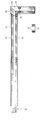
- FIG. 1 is a perspective view illustrating a state in which a stud is installed and fixed to a runner installed on a ceiling and a bottom surface
- FIG. 4 is a side cross-sectional view illustrating a state in which a stud is fixed to both sides in a width direction of a runner installed on a floor surface
- FIG. 7 is a cross-sectional view of the finishing panel having the elastic coupling member fixed to the left and right both ends of the inner side from above
- FIG. 7 is a cross-sectional view of the finishing panel where the elastic coupling member is fixed to the plurality of studs.
- FIG. 9 is a side cross-sectional view illustrating a state in which a runner, stud, a closing panel, an elastic coupling member, a baseboard, and a molding member are coupled
- FIG. 12 is a perspective view illustrating a state in which an electronic product is installed in an opening of the closing panel.
- the prefabricated wall for interior includes a runner 10 which is installed to face the ceiling and the floor, a plurality of studs 20 that are installed and fixed in the vertical direction on both sides of the runner 10 in a width direction, and a plurality of It is configured to include a finishing panel 30 coupled to the stud 20, it is used to partition the interior space of the building.
- the runner 10 and the stud 20 are components forming a skeleton for supporting the prefabricated wall according to the present invention.
- finishing panel 30 is a flat member that forms most of the side portions of the interior prefabricated wall according to the present invention, and is installed at the front of the plurality of studs 20 fixed to both sides of the runner 10.
- the finishing panel 30 may be manufactured in various sizes, and for example, MDF panels or foam boards having a width of 1220 mm and a length of 2440 mm may be used, and the outer surface of the finishing panel 30 may have various colors and patterns. It can be a lapping treatment coated with a film or the like. In addition, the finishing panel 30 may be manufactured to have a sufficient width according to the size of the electronic product, etc. installed in the opening 35.
- a pair of elastic coupling members 31 extend in the vertical direction on both left and right ends of the inner surface of the finishing panel 30 (the upper surface of the finishing panel in FIGS. 6 and 7). Combined and fixed.
- the finishing panel 30 is coupled to the plurality of studs 20 through the pair of elastic coupling members 31.
- the elastic coupling member 31 will be described later.
- FIG. 2 is a cross-sectional view showing a runner.
- the runner 10 is a member which is installed and fixed to the ceiling and the bottom surface in order to fix the upper and lower ends of the studs 20 when the prefabricated wall is installed by the dry method.
- the base part 11 and the mounting frame part 12 are fixed. ).
- the base portion 11 is formed to be sufficiently long with a constant width as a portion fixed to the ceiling or the bottom surface and fixed by a screw or the like.
- the mounting frame portion 12 is formed in the form of a hollow hollow column as a whole, the present invention is not necessarily limited to this, an empty space is formed in the longitudinal direction inside the mounting frame portion 12, Both sides of the mounting frame portion 12 should be formed parallel to each other, the upper surface may be formed in various shapes such as inclined or curved surface, as shown in Figure 9, the upper surface of the mounting frame portion 12 In the part, a through hole 125 for passing an insulated wire for supplying electric power to an electronic product installed in the opening 35 of the finishing panel 30 may be formed.
- the mounting frame portion 12 is such that the spaced space of the same width as the mounting frame portion 12 is formed between the stud 20 is fixed to both sides, by installing a sound insulation material in the space between the stud 20 It improves the sound insulation performance of the wall, or passes through an insulated wire for supplying power to an electronic product installed in the opening 35 of the finish panel 30, and the like. Therefore, by appropriately designing the width of the mounting frame portion 12 in accordance with the required sound insulation performance or the size of the electronic product installed in the opening 35 of the finishing panel 30, it is possible to meet various requirements.
- a stud latching jaw that protrudes so as to take longitudinal ends of each of the plurality of studs 20 fixed to both side surfaces in the width direction of the mounting frame portion 12. (Not shown) may be formed to extend in the longitudinal direction.
- the runner 10 is installed in such a manner that the base 11 is tightly fixed to the ceiling or the bottom surface by a screw or the like on both sides of the portion where the mounting frame portion 12 is formed.
- the part protrudes from the base part 11, and the stud catching jaw is formed to protrude higher than the head of the screw so that the end of the stud 20 comes into close contact with the side of the mounting frame part 12 of the stud 20.
- the end is not caught by the head of the screw, and the function of allowing the stud 20 to be engaged in a certain position.
- a base plate coupling groove 110 for inserting and coupling the runner coupling piece 410 of the base plate 40 to be described later is formed to extend in the longitudinal direction.
- the runner 10 having such a configuration may be made of various materials, but in general, it is preferable to be made of aluminum or aluminum alloy material having good processability, and the ceiling and the floor at a predetermined position to partition the interior space of the building. It will be installed to face the surface.
- 3 is a plan view of the stud seen from above.
- Stud 20 is a component that is a skeleton for coupling the finishing panel 30 is coupled to the runner 10 fixed to both ends in the longitudinal direction installed on the ceiling and the bottom surface, shown in Figures 1 and 4 As described above, the both sides of the mounting frame portion 12 of the runner 10 fixed to the ceiling and the bottom surface are in close contact with each other in the width direction and are fixed by screws or the like.
- the stud 20 is provided with a pair of coupling grooves 21 for inserting and engaging the protrusion 312 of the elastic coupling member 31, such a pair of coupling grooves 21.
- One or more locking jaws 2100 are formed to extend in the longitudinal direction on the left inner surface and the right inner surface of the pair of coupling grooves 21.
- the stud 20 since the stud 20 has a shape that is relatively longer in length than the width, the lateral strength of the stud 20 installed in the vertical direction may be insufficient, and thus, between the plurality of studs 20 installed in the vertical direction. It is also possible to reinforce the transverse strength of the stud 20 by installing and fixing a suitable reinforcing member (not shown) in the horizontal direction.
- the stud 20 having such a configuration may be made of various materials, but generally, it is preferable that the stud 20 is made of aluminum or an aluminum alloy material having good workability.
- FIG. 5 is a cross-sectional view showing the elastic coupling member.
- the elastic coupling member 31 is fixedly coupled to extend in the vertical direction at both left and right ends of the inner surface of the finishing panel 30 so that the elastic coupling member 31 is inserted into the coupling groove 21 of the stud 20 so that the plurality of studs 20 of the finishing panel 30 can be inserted.
- the contact portion 311 is a portion that is in close contact with the inner surface of the finishing panel 30, the protrusion 312 is a portion that is inserted into the coupling groove 21 of the stud 20, the inner side from the contact portion 311 (in Figure 5) Protrude in the upper direction) and extend in the longitudinal direction.
- the protrusion 312 is provided with a separation groove 312a which is formed concave in the longitudinal direction at the center thereof, such that the left coupling piece 312b and the right coupling piece 312c are formed at left and right sides of the separation groove 312a. ) Is formed.
- the separation groove 312a is formed to have a substantially rectangular cross section, and the left and right sides of the separation groove 312a may be formed in parallel with each other, but the elastic coupling of the left coupling piece 312b and the right coupling piece 312c is reduced. In order to prevent the lowering of the restoring force caused by the tape, it is preferable to be formed about 2 to 5 ° outward.
- one or more coupling protrusions 3120 are formed to extend in the length direction on the left side of the left coupling piece 312b and the right side of the right coupling piece 312c so as to be caught by the locking step 2100.
- the engaging projection 2120 and the engaging projection 3120 of the stud 20 and the elastic engaging member 31 of the stud 20 is easy to be inserted into the engaging groove 21, but the projection 312
- the protrusion 312 is preferably inclined in one direction so that it is difficult to separate from the coupling groove 21.
- the elastic coupling member 31 may further include a panel side closing wing 313 for wrapping the side portion of the closing panel 30.
- the panel side finishing wing 313 is formed from one end of the contact portion 311 so as to surround the side portion of the finishing panel 30 when the elastic coupling member 31 is fixedly coupled to both left and right ends of the inner surface of the finishing panel 30. It is bent and formed to extend in the longitudinal direction.
- the elastic coupling member 31 may be made of a synthetic resin having sufficient elasticity, or the like, and may be made of, for example, a rubber material having a hardness of 5.5.
- the elastic coupling member 31 is fixed to the inner side surface of the finish panel 30 by using a screw or a nailer on the lower surface of the separation groove 312a.
- the length of the elastic coupling member 31 is formed slightly shorter than the length of the finish panel 30 is fixed to the finish panel 30, as shown in Figure 9, the upper portion of the base 40 to be described later Is preferably located inside the bottom of the finishing panel 30.
- the elastic coupling member 31, the elastic piece 32 for preventing the reduction of the restoring force due to the elastic degradation of the left coupling piece (312b) and the right coupling piece (312c) is separated groove ( 312a) may be fixed to the inner surface of the finishing panel 30 together with the elastic piece 32 by screws or taka in the inserted state.
- the elastic piece 32 may be formed to extend in the longitudinal direction in a cross-section of a 'U' shape, such as a metal material having high elasticity, such as spring steel, but the present invention is not limited thereto, and the left coupling piece 312b and The right coupling piece 312c may be formed in various cross-sectional shapes capable of preventing a decrease in restoring force due to a decrease in elasticity.
- the prefabricated wall for interior according to the invention may further comprise a gapper (80).
- FIG. 10 is a cross-sectional view of a gapper
- FIG. 11 is a front view of a prefabricated wall showing a state in which a gapper is compressed between a plurality of finishing panels.
- Gapper 80 is a component that is installed to be pressed between the plurality of finishing panels 30 forming a side portion of the prefabricated wall according to the invention to close and close between the adjacent finishing panels 30, a pair of The panel side crimping piece 81 and the center connection part 82 are comprised.
- the panel side finishing wings 313 may be disposed between the adjacent finishing panels 30. In close contact with each other, the gap is filled with gaps (figure 7).
- the length of the elastic coupling member 31 is formed to be slightly shorter than the length of the finishing panel 30 is fixed to the finishing panel 30, the upper and lower ends between the adjacent finishing panel 30 There will be a portion that is not closed by the panel side closure wings 313, and the gaffer 80 is used to fill and close these unclosed gaps.
- the pair of panel side pressing pieces 81 are in contact with the side portions of the finishing panel 30, respectively, and are formed to extend in the longitudinal direction in a substantially flat plate shape, and the center connection part in the state where the gaffer 80 is not deformed. It is preferable that it is formed to have an angle of about 4 to 10 degrees with respect to (82).
- the center connection portion 82 is a portion connecting the ends of the pair of panel side pressing pieces 81, and in the process of installing the gaffer 80 between the adjacent finishing panels 30, the pair of panel side pressing pieces 81 is compressed by being gathered to the center around the central connection portion 82 by the side portion of the angle finishing panel 30 (see Fig. 11).
- the center connecting portion 82 is shown to have a shape having a width wider than the sum of the thicknesses of the pair of panel side pressing pieces 81, but the center connecting portion 82 may have such an externally distinct shape. It may not be formed, and may be manufactured in various shapes (externally distinguished from the panel side press pieces) as long as the pair of panel side press pieces 81 can be connected with sufficient strength.
- the gaffer 80 is made to have a sufficient length, and then cut to the same length as the length of the portion that is not closed by the panel side finishing wing 313 at the upper and lower ends between the adjacent finishing panel 30, Compression is installed between the finishing panel 30 adjacent to each other.
- the gaffer 80 may be made of a synthetic resin having sufficient elasticity, for example, may be made of a rubber material of hardness 5.5.
- Prefabricated wall for interior according to the invention may further comprise a baseboard 40 and the molding member (50).
- the base 40 is a component that functions to block a portion from the ceiling or the bottom surface to the position where the finishing panel 30 is installed (see FIG. 12), and the runner coupling piece 410 and the molding coupling groove 420. It is configured to include, and is formed in a long rectangular plate shape as a whole.
- the runner coupling piece 410 is inserted into the baseboard coupling groove 110 of the runner 10 so that the baseboard 40 is coupled to both sides of the runner 10 in the width direction, and the ceiling of the baseboard 40 is provided. Or bent inward (leftward in FIG. 8) from an end adjacent to the bottom (downward in FIG. 8) to extend in the longitudinal direction.
- the molding coupling groove 420 is a portion into which the baseboard coupling portion 510 of the molding member 50 to be described below is inserted and coupled, and is adjacent to the ceiling or bottom surface of the baseboard 40 (the downward direction in FIG. 8). It is formed to extend in the longitudinal direction at the end.
- the molding coupling groove 420 is shown in a shape that is opened downward in a direction end adjacent to the ceiling or the bottom surface of the base 40, but the present invention is not limited thereto, and the molding coupling groove 420 is not limited thereto.
- the base member coupling portion 510 of the molding member 50 is also formed to have a corresponding cross-sectional shape.
- the molding coupling groove 420 is formed of a dovetail shape or 'T' shaped cross section so that the baseboard coupling portion 510 formed to have a corresponding cross-sectional shape is not easily separated after being inserted into the molding coupling groove 420. It is preferable.
- the base plate 40 may be made of various materials, but generally, it is preferable to make the aluminum plate or aluminum alloy material having good workability.
- the molding member 50 is a component having a function of covering between one end of the base 40 and the ceiling or the bottom surface, and comprises a base receiving portion 510 and the edge finish 520.
- the baseboard coupling part 510 is inserted into the molding coupling groove 420 of the baseboard 40 so that the molding member 50 is coupled to one side of the baseboard 40, and one side of the molding member 50. Is formed to extend in the longitudinal direction in the dovetail shape or 'T' cross-sectional shape.
- the corner finishing part 520 is a part which covers the corner between the one end of the base 40 and the ceiling or the bottom surface when the base plate 40 is installed, as if the silicone finish is finished. It is formed obliquely from one end.
- the edge finish part 520 may be formed to be inclined closer to the vertical direction than 45 ° so as to more reliably contact the ceiling or the bottom surface.
- the base member 40 to which the molding member 50 is coupled is installed on both sides in the width direction of the runner 10 fixed to the ceiling or the bottom surface, one side of the edge finish part 520 in the width direction is the base plate 40. ) And the other side is in contact with the ceiling or floor.
- the molding member 50 may be made of a synthetic resin having sufficient elasticity and flexibility, and is preferably made of a rubber material having a low hardness.
- the prefabricated wall for interior according to the invention may further comprise a column assembly 60.
- FIG. 13 is a cross-sectional view of the column assembly, the first column member, the edge column member, and the second column member viewed from above
- FIG. 14 is a cross-sectional view of the wall bent and finished by the column assembly and the end column member. .
- the column assembly 60 is a component in which walls formed by the finishing panel 30 coupled to the plurality of studs 20 are adjacent to each other to form an edge or intersect each other.
- the first column member 61 is a member coupled to one side of the finish panel 30 at the inner side of the corner formed by the walls formed by the finish panel 30 coupled to the plurality of studs 20 are adjacent to each other. As shown in FIG. 1, a first engaging jaw 611 extending in a longitudinal direction on both sides of an inner edge and a first engaging groove extending in a longitudinal direction on an outer side of the first engaging jaw 611. And 615.
- the first latching jaw 611 is a portion on which one side of the closing panel 30 forming a wall is caught, and the first coupling groove 615 of the outer side thereof is elastically coupled to the closing panel 30.
- the protrusion 312 is a portion formed to be inserted and coupled.
- one or more locking jaws are formed to extend in the longitudinal direction on both inner side surfaces of the first coupling groove 615, and the left side and the right coupling piece 312c of the left coupling piece 312b when the protrusion 312 is inserted.
- One or more coupling protrusions 3120 formed on the right side of the first side are caught by one or more locking jaws of the inner side of the first coupling groove 615.
- the second column member 63 is a member coupled to one side of the width direction one side of the finishing panel 30 forming a wall and the other side coupled to one side of the width direction of the edge column member 62 which will be described later.
- the second engaging groove 635 is formed extending in the longitudinal direction and the second engaging projection 631 is formed to extend in the longitudinal direction on one side of the second coupling groove 635.
- the second latching jaw 631 is a portion on which one side of the finishing panel 30 forming a wall is caught, and the second coupling groove 635 outside the elastic coupling member 31 is fixedly coupled to the finishing panel 30.
- the protrusion 312 is a portion formed to be inserted and coupled.
- one or more locking jaws are formed to extend in the longitudinal direction on both inner side surfaces of the second coupling groove 635, and the left side and the right coupling piece 312c of the left coupling piece 312b when the protrusion 312 is inserted.
- One or more coupling protrusions 3120 formed on the right side of the second hook is caught by one or more locking jaws of the inner side of the second coupling groove 635.
- the coupling piece is formed to extend in the longitudinal direction in a dovetail shape or a 'T' shaped cross section, and the edge column member It is preferable not to be easily separated after being inserted into the engaging groove formed to have a cross-sectional shape corresponding to both ends in the width direction of the 62.
- the edge column member 62 is a member that forms an outer edge of the corner of the wall adjacent to each other, has an approximately '-' cross-sectional shape and is formed to extend in the longitudinal direction, and each of the second column members on both sides in the width direction. (63)
- the coupling groove to which the other side of the coupling piece is inserted and coupled is formed to extend in the longitudinal direction in the shape of a dovetail or 'T' shape.
- the coupling piece is formed at the other side in the width direction of the second column member 63 and the coupling groove is formed at both sides in the width direction of the edge column member 62
- the present invention is not limited thereto.
- the coupling groove may be formed on the other side in the width direction of the two column members 63
- the coupling pieces may be formed on both sides in the width direction of the edge column member 62
- the coupling groove is formed on one side in the width direction of the edge column member 62. Is formed and the other side may be formed with a coupling piece.
- the walls may be configured to cross in a 'T' shape.
- the walls may be configured to intersect in a '+' shape.
- the second column member 63 having different coupling pieces formed on the other side in the width direction of one second column member 63 of the two second column members 63. It is inserted into the coupling groove formed on the other side of the width direction will be coupled.
- the column assembly 60 is configured by at least one or more combinations of the first column member 61, the edge column member 62, and the second column member 63, so that the wall is bent freely or crossed. In this case, even when the wall is not orthogonal and has a cross angle slightly shifted from the right angle, the wall can be installed without difficulty.
- Prefabricated wall for interior according to the invention may further comprise an end column member (70).
- the end column member 70 is a member coupled to the side end of the wall formed by the finishing panel 30 coupled to the plurality of studs 20 to close the end of the wall. It has a '-shaped cross-sectional shape is formed to extend in the longitudinal direction, the elastic coupling member 31 is fixed to the inner surface in one side in the width direction. Therefore, the end column member 70 is coupled to the stud 20 by inserting the protrusion 312 of the elastic coupling member 31 into the coupling groove 21 of the stud 20.
- the other end portion in the width direction is formed with a coupling piece or coupling groove is coupled to the coupling groove or coupling piece formed at one end in the width direction of the other end column member 70.
- the coupling piece or the coupling groove is formed to extend in the longitudinal direction in the dovetail shape or 'T'-shaped cross section, it is preferable not to be easily separated after being combined with each other.
- the runner 10 is installed to face each other on the ceiling or the floor at a predetermined position based on the design specification. That is, a reference line is displayed on the ceiling or the bottom surface, the runner 10 is brought into close contact with the ceiling or the bottom surface in accordance with the displayed reference line, and then the base 11 is screwed on both sides of the portion where the mounting frame portion 12 is formed. To be fixed.
- the plurality of studs 20 are fixed between the runners 10 fixed to the ceiling and the bottom surface, respectively. That is, the rear surface of each of the longitudinal end of each of the plurality of studs 20 is in close contact with the side of the width direction of the mounting frame portion 12 of the runner 10 and then fixed in a vertical direction by using a screw or the like.
- the base member coupling portion 510 of the molding member 50 is inserted into the molding coupling groove 420 of the base member 40 to run the base plate 40 coupled with the molding member 50.
- the molding member The base plate 40 coupled with the 50 is installed near the ceiling and the bottom surface, and the edge finishing portion 520 of the molding member 50 is brought into contact with the ceiling and the bottom surface.
- the finishing panel 30 having the elastic coupling member 31 coupled and fixed in the vertical direction to the left and right both ends of the inner side surface is coupled to the front surface of the plurality of studs 20. That is, the protrusion 312 of the elastic coupling member 31 fixed to both ends of the finishing panel 30 is inserted into the coupling groove 21 of the plurality of studs 20 so that the finishing panel 30 is connected to the plurality of studs 20.
- the side portion of the interior prefabricated wall according to the present invention is completed.
- the length of the elastic coupling member 31 is fixed to the left and right both ends of the inner surface of the finish panel 30 is slightly shorter than the length of the finish panel 30, the finish panel 30 a plurality of studs (20)
- the lower end of the elastic coupling member 31 is fixed to the left and right both ends of the inner surface of the finishing panel 30 of the base plate 40 located in the lower inner side of the finishing panel 30 Supported by the upper part, the finishing panel 30 is prevented from sliding down the longitudinal direction of the stud 20 provided in the vertical direction.
- the finishing panel 30 is installed on the lower side
- the other finishing panel 30 is installed on the upper side, the upper finishing panel 30 is supported by the lower finishing panel 30.
- a process of compressing the gapper 80 may be further included in a portion which is not closed by the panel side closing wing 313 at the upper end and the lower end between the adjacent finishing panels 30.
- the gap (gap) between the adjacent finishing panels 30 are completely filled and finished.
- home appliances such as TVs, computers, flat panel displays, air conditioners, humidifiers, air purifiers, and electrical outlets are provided in the openings 35 of the finishing panel 30.
- the insulated wire is electrically connected to a home appliance or an electrical outlet for power supply. That is, between the back surface of the stud 20 in which the insulated wire is fixed to both side surfaces in the width direction of the mounting frame portion 12 through the through hole 125 formed in the upper surface portion of the mounting frame portion 12 in the center of the runner 10.
- the insulated wire is electrically connected to a home appliance or an electrical outlet by passing through the space and the inner space of the mounting frame portion 12.
- the insulated wire is electrically connected to the home appliance or the electrical outlet after the home appliance or the electrical outlet is installed in the opening 35 of the finishing panel 30, but the insulated wire is connected through the through hole 125.
- an electrical outlet or the like may be provided to electrically connect the insulated wire and the home appliance or the electrical outlet.
- the first column member 61, the edge column member 62 and the second column member 63 The column assembly 60 formed by combining at least one of the () is coupled to the side end of the wall. That is, the column assembly 60 is inserted into the first coupling groove 615 or the second coupling groove 635 by inserting the protrusion 312 of the elastic coupling member 31 fixed to the side end portion of the wall finishing panel 30. By joining the walls, the walls are adjacent to each other to form corners or to cross each other.
- the end column member 70 is coupled to the side end of the wall formed by the finishing panel 30. That is, by inserting the protrusion 312 of the elastic coupling member 31 fixedly coupled to the inner surface of one side in the width direction of the end column member 70 into the coupling groove 21 of the stud 20 to close the end of the wall. do.
- the construction process as described above may be performed at a time by a small number of personnel.
- simple assembly is not completed and requires different tasks such as silicone finishing the corners between the one end of the baseboard and the ceiling or floor surface. Should be dealt with. Therefore, after the assembling work is completed, another worker arrives and additional work days are required to complete the remaining work, which has a disadvantage in that the construction period is long.
- the prefabricated wall for interior according to the present invention can be carried out by a small number of people at a time, so labor costs can be reduced and air can be shortened.
- the prefabricated wall for interior according to the present invention has the advantage of minimizing the use of screws to facilitate the installation, disassembly and reassembly of the wall.
- the installation or dismantling work can be performed by a small number of people at a time, labor costs are reduced and the air is shortened.
- first and second corner column member and the edge column member can be configured freely so that the wall is bent or intersected, even if the wall is not orthogonal and has a crossing angle slightly shifted from the right angle, there is an advantage that can be installed without difficulty have.
- the sound insulating material is provided in the space between the rear surface of the stud installed on both sides of the runner to obtain excellent sound insulation performance.
- base portion 110 base plate coupling groove
- mounting frame portion 125 through hole
- first engaging jaw 615 first coupling groove
- the present invention relates to a prefabricated wall for interior and its construction method, the installation and disassembly and reassembly of the wall is easy by minimizing the use of screws, the installation or dismantling work can be done by a few people at a time and labor costs are reduced and air It can be shortened and can be utilized in the prefabricated wall manufacturing industry.
Landscapes
- Engineering & Computer Science (AREA)
- Architecture (AREA)
- Physics & Mathematics (AREA)
- Electromagnetism (AREA)
- Civil Engineering (AREA)
- Structural Engineering (AREA)
- Finishing Walls (AREA)
- Load-Bearing And Curtain Walls (AREA)
Abstract
Priority Applications (6)
| Application Number | Priority Date | Filing Date | Title |
|---|---|---|---|
| US16/304,084 US10662646B2 (en) | 2016-05-26 | 2017-03-24 | Prefabricated wall for interior and construction method therefor |
| PH1/2018/502479A PH12018502479B1 (en) | 2016-05-26 | 2017-03-24 | Prefabricated wall for interior and construction method therefor |
| EP17802972.4A EP3467225B1 (fr) | 2016-05-26 | 2017-03-24 | Mur préfabriqué pour intérieur et son procédé de construction |
| AU2017270959A AU2017270959B2 (en) | 2016-05-26 | 2017-03-24 | Prefabricated wall for interior and construction method therefor |
| JP2018561032A JP6749420B2 (ja) | 2016-05-26 | 2017-03-24 | インテリア用組み立て式壁体及びその施工方法 |
| CN201780030254.XA CN109154156B (zh) | 2016-05-26 | 2017-03-24 | 装饰用组装式墙体及其施工方法 |
Applications Claiming Priority (2)
| Application Number | Priority Date | Filing Date | Title |
|---|---|---|---|
| KR10-2016-0064635 | 2016-05-26 | ||
| KR1020160064635A KR101705134B1 (ko) | 2016-05-26 | 2016-05-26 | 인테리어용 조립식 벽체 및 그 시공 방법 |
Publications (1)
| Publication Number | Publication Date |
|---|---|
| WO2017204453A1 true WO2017204453A1 (fr) | 2017-11-30 |
Family
ID=58154604
Family Applications (1)
| Application Number | Title | Priority Date | Filing Date |
|---|---|---|---|
| PCT/KR2017/003220 Ceased WO2017204453A1 (fr) | 2016-05-26 | 2017-03-24 | Mur préfabriqué pour intérieur et son procédé de construction |
Country Status (8)
| Country | Link |
|---|---|
| US (1) | US10662646B2 (fr) |
| EP (1) | EP3467225B1 (fr) |
| JP (1) | JP6749420B2 (fr) |
| KR (1) | KR101705134B1 (fr) |
| CN (1) | CN109154156B (fr) |
| AU (1) | AU2017270959B2 (fr) |
| PH (1) | PH12018502479B1 (fr) |
| WO (1) | WO2017204453A1 (fr) |
Cited By (1)
| Publication number | Priority date | Publication date | Assignee | Title |
|---|---|---|---|---|
| WO2024132083A1 (fr) * | 2022-12-22 | 2024-06-27 | Knauf Gips Kg | Système de cloison sèche et procédé pour ériger une cloison sèche |
Families Citing this family (18)
| Publication number | Priority date | Publication date | Assignee | Title |
|---|---|---|---|---|
| US10377569B1 (en) * | 2018-03-29 | 2019-08-13 | Nashville Wire Products Manufacturing Company, Llc | Perforated decking |
| CN108360726B (zh) * | 2018-04-03 | 2023-08-15 | 苏州美瑞德建筑装饰有限公司 | 大体量镜面不锈钢吊顶安装结构 |
| USD946950S1 (en) * | 2018-04-10 | 2022-03-29 | SieMatic Möbelwerke GmbH & Co. KG | Section for furniture |
| USD923822S1 (en) | 2018-09-12 | 2021-06-29 | Megawall Pty Ltd | Connector for a building panel |
| USD942786S1 (en) * | 2018-10-18 | 2022-02-08 | SieMatic Möbelwerke GmbH & Co. KG | Furniture section |
| CN110924569A (zh) * | 2019-10-24 | 2020-03-27 | 江苏东曌建筑产业创新发展研究院有限公司 | 一种装配用构件及安装方法 |
| KR102165280B1 (ko) | 2019-12-27 | 2020-10-13 | (주)헤드어반스튜디오 | 인테리어용 조립식 벽체 구조물 및 이를 이용한 인테리어 벽체의 시공 방법 |
| CN112064826B (zh) * | 2020-08-07 | 2021-10-26 | 华信咨询设计研究院有限公司 | 一种预制装配式装饰墙板安装方法 |
| KR102187366B1 (ko) | 2020-09-01 | 2020-12-04 | 김형수 | 인테리어 시공 방법 |
| KR102461092B1 (ko) | 2020-11-11 | 2022-10-31 | 서울대학교산학협력단 | 프리패브 전단벽모듈 연결구조 |
| KR102596627B1 (ko) | 2020-11-27 | 2023-11-03 | 서울대학교산학협력단 | 친환경 하이브리드 목재슬라브 |
| KR20230010946A (ko) | 2021-07-13 | 2023-01-20 | 주식회사 셀레스트 디자인 | 디스플레이 패널을 이용한 인테리어 시공방법 |
| KR20230010947A (ko) | 2021-07-13 | 2023-01-20 | 주식회사 셀레스트 디자인 | 인테리어 시공방법 |
| CN114263294B (zh) * | 2022-01-21 | 2024-02-09 | 洛阳北玻轻晶石新材料有限公司 | 一种装配式冷弯轻钢龙骨框架结构 |
| USD1078108S1 (en) * | 2022-02-15 | 2025-06-03 | 2840629 Ontario Inc. | Wall/ceiling panel |
| US20240060295A1 (en) * | 2022-08-17 | 2024-02-22 | A&C Future, Inc. | Collapsible Prefabricated Mechanical Soft Wall |
| CN116335183B (zh) * | 2023-03-02 | 2025-04-11 | 合肥工大建设监理有限责任公司 | 一种基坑监测系统 |
| CN117627229A (zh) * | 2024-01-02 | 2024-03-01 | 中国十七冶集团有限公司 | 一种装配式轻质隔墙安装固定装置及使用方法 |
Citations (5)
| Publication number | Priority date | Publication date | Assignee | Title |
|---|---|---|---|---|
| KR20000049102A (ko) * | 1996-10-11 | 2000-07-25 | 루드덕 딕코리 | 건축 요소 |
| JP2008111336A (ja) * | 2001-06-07 | 2008-05-15 | Telezygology Inc | 建築部材 |
| KR20100091054A (ko) * | 2009-02-09 | 2010-08-18 | 현대산업개발 주식회사 | 가변형 경량벽체 |
| KR20100107702A (ko) * | 2009-03-26 | 2010-10-06 | 주식회사 케이씨씨 | 이동형 칸막이 |
| JP2014185462A (ja) * | 2013-03-22 | 2014-10-02 | Toto Ltd | 浴室コーナ部の壁パネル連結構造 |
Family Cites Families (22)
| Publication number | Priority date | Publication date | Assignee | Title |
|---|---|---|---|---|
| GB286137A (en) * | 1927-06-17 | 1928-03-01 | Alfred Goerlitzer | Improvements in lifting-jacks |
| JPS515944Y1 (fr) * | 1969-03-28 | 1976-02-18 | ||
| JPS5244336Y2 (fr) * | 1972-03-24 | 1977-10-07 | ||
| LU74328A1 (fr) * | 1975-02-27 | 1976-08-13 | ||
| GB2300867B (en) * | 1995-05-15 | 1998-07-29 | Chingdar Enterprise Co Limited | Partition wall |
| JP3973172B2 (ja) * | 1997-09-19 | 2007-09-12 | 株式会社ウッドワン | 間仕切り壁の固定構造 |
| KR19990028005U (ko) | 1997-12-24 | 1999-07-15 | 신용운 | 건축용 조립식 패널 |
| KR200224857Y1 (ko) | 1999-02-24 | 2001-05-15 | 조창걸 | 싱크대용 걸레받이 |
| JP2001090229A (ja) * | 1999-09-21 | 2001-04-03 | Sekisui Chem Co Ltd | 壁パネルの接続構造 |
| CN2447257Y (zh) * | 2000-09-28 | 2001-09-12 | 印秀龙 | 摩托车助力式双撑脚 |
| EP1349992A1 (fr) * | 2000-12-11 | 2003-10-08 | N.V. Kema | Systeme de paroi |
| CN2522489Y (zh) * | 2002-03-01 | 2002-11-27 | 陈正义 | 组合隔间 |
| NL1023330C2 (nl) * | 2003-05-02 | 2004-11-09 | Snelwand B V | Systeem en werkwijze voor het bouwen en demonteren van wanden. |
| NL1028021C2 (nl) * | 2004-01-15 | 2005-07-18 | Robert Johan Verheul | Scheidingswand. |
| KR100695700B1 (ko) | 2005-04-20 | 2007-03-15 | 김세중 | 조립식 경량벽체 패널과 그 조립구조 |
| KR100838961B1 (ko) | 2006-08-08 | 2008-06-16 | 주식회사 엘지화학 | 착탈식 건식벽체 |
| US7661237B2 (en) * | 2006-12-11 | 2010-02-16 | Haworth, Ltd. | Skin attachment structure for wall system |
| MX2009008183A (es) * | 2007-02-01 | 2010-02-17 | Marlite Inc | Sistema de panel de pared. |
| JP5399680B2 (ja) * | 2008-10-08 | 2014-01-29 | 株式会社岡村製作所 | パネル体間の隙間閉塞部材 |
| CN201546346U (zh) * | 2009-11-16 | 2010-08-11 | 上海阁敦思工程项目管理咨询有限公司 | 建筑装配式内隔墙系统 |
| CN203873334U (zh) * | 2014-04-22 | 2014-10-15 | 中山市西威厨房设备制造有限公司 | 用于橱柜的踢脚挡板组件 |
| KR101529009B1 (ko) | 2014-11-06 | 2015-06-15 | 이청종 | 착탈식 벽체 프레임 조립체 및 그 시공방법 |
-
2016
- 2016-05-26 KR KR1020160064635A patent/KR101705134B1/ko not_active Expired - Fee Related
-
2017
- 2017-03-24 EP EP17802972.4A patent/EP3467225B1/fr active Active
- 2017-03-24 WO PCT/KR2017/003220 patent/WO2017204453A1/fr not_active Ceased
- 2017-03-24 US US16/304,084 patent/US10662646B2/en not_active Expired - Fee Related
- 2017-03-24 AU AU2017270959A patent/AU2017270959B2/en not_active Ceased
- 2017-03-24 JP JP2018561032A patent/JP6749420B2/ja not_active Expired - Fee Related
- 2017-03-24 CN CN201780030254.XA patent/CN109154156B/zh not_active Expired - Fee Related
- 2017-03-24 PH PH1/2018/502479A patent/PH12018502479B1/en unknown
Patent Citations (5)
| Publication number | Priority date | Publication date | Assignee | Title |
|---|---|---|---|---|
| KR20000049102A (ko) * | 1996-10-11 | 2000-07-25 | 루드덕 딕코리 | 건축 요소 |
| JP2008111336A (ja) * | 2001-06-07 | 2008-05-15 | Telezygology Inc | 建築部材 |
| KR20100091054A (ko) * | 2009-02-09 | 2010-08-18 | 현대산업개발 주식회사 | 가변형 경량벽체 |
| KR20100107702A (ko) * | 2009-03-26 | 2010-10-06 | 주식회사 케이씨씨 | 이동형 칸막이 |
| JP2014185462A (ja) * | 2013-03-22 | 2014-10-02 | Toto Ltd | 浴室コーナ部の壁パネル連結構造 |
Non-Patent Citations (1)
| Title |
|---|
| See also references of EP3467225A4 * |
Cited By (1)
| Publication number | Priority date | Publication date | Assignee | Title |
|---|---|---|---|---|
| WO2024132083A1 (fr) * | 2022-12-22 | 2024-06-27 | Knauf Gips Kg | Système de cloison sèche et procédé pour ériger une cloison sèche |
Also Published As
| Publication number | Publication date |
|---|---|
| CN109154156B (zh) | 2021-02-26 |
| PH12018502479A1 (en) | 2019-09-30 |
| JP2019518890A (ja) | 2019-07-04 |
| PH12018502479B1 (en) | 2023-08-30 |
| EP3467225B1 (fr) | 2024-02-14 |
| CN109154156A (zh) | 2019-01-04 |
| EP3467225A1 (fr) | 2019-04-10 |
| AU2017270959B2 (en) | 2020-03-12 |
| EP3467225A4 (fr) | 2020-04-22 |
| US10662646B2 (en) | 2020-05-26 |
| KR101705134B1 (ko) | 2017-02-09 |
| JP6749420B2 (ja) | 2020-09-02 |
| AU2017270959A1 (en) | 2018-12-13 |
| US20200032507A1 (en) | 2020-01-30 |
Similar Documents
| Publication | Publication Date | Title |
|---|---|---|
| WO2017204453A1 (fr) | Mur préfabriqué pour intérieur et son procédé de construction | |
| WO2011028071A2 (fr) | Corps de carreau emboîtable | |
| WO2010114236A2 (fr) | Article de parquet | |
| US6557311B1 (en) | Retromolding extender | |
| WO2017018854A1 (fr) | Système de porte et de fenêtre de couverture externe double de mur rideau et son procédé de fabrication | |
| WO2011046283A1 (fr) | Panneau de pierre de construction et son procédé de fabrication, et panneau de porte utilisant le panneau de pierre de construction | |
| WO2014196750A1 (fr) | Fenêtre composite et procédé pour son isolation thermique au moyen d'un matériau d'isolation thermique non adhésif | |
| GB2147152A (en) | Skirting board structure for the distribution of electric energy and other similar services in civil use premises | |
| US5056287A (en) | Panel mounting construction and method of use | |
| CN109072609A (zh) | 具有外部导管接合功能的预制分户壁 | |
| WO2016153205A1 (fr) | Cadre destiné à une armoire de dispositif de communication électronique, et armoire le comprenant | |
| KR100863265B1 (ko) | 배선 덕트의 연결구 | |
| RU2429332C1 (ru) | Комплект плинтусных профилей | |
| EP3810994A1 (fr) | Ensemble panneau et appareil ménager le comprenant | |
| WO2024076082A1 (fr) | Ensemble bloc préfabriqué sans pièce pour paroi temporaire | |
| WO2015008907A1 (fr) | Panneau et structure de liaison entre panneaux | |
| JPH0886033A (ja) | 間仕切壁構造 | |
| KR102031114B1 (ko) | 조립식 결합구조를 갖는 천정패널 | |
| WO2023018300A1 (fr) | Paroi temporaire ayant une robustesse améliorée | |
| WO2020075992A1 (fr) | Maison préfabriquée | |
| JP2946408B2 (ja) | 入口枠装置及び入口部の施工方法 | |
| WO2021020874A1 (fr) | Système de paroi utilisant des modules en nid d'abeilles | |
| WO2017003145A1 (fr) | Ensemble de mise en œuvre d'un matériau d'isolation sous vide et procédé de mise en œuvre de matériau d'isolation sous vide | |
| JPS6126416A (ja) | 間仕切壁の配線構造 | |
| WO2025071374A1 (fr) | Module de système polygonal pour construction |
Legal Events
| Date | Code | Title | Description |
|---|---|---|---|
| ENP | Entry into the national phase |
Ref document number: 2018561032 Country of ref document: JP Kind code of ref document: A |
|
| NENP | Non-entry into the national phase |
Ref country code: DE |
|
| 121 | Ep: the epo has been informed by wipo that ep was designated in this application |
Ref document number: 17802972 Country of ref document: EP Kind code of ref document: A1 |
|
| ENP | Entry into the national phase |
Ref document number: 2017270959 Country of ref document: AU Date of ref document: 20170324 Kind code of ref document: A |
|
| ENP | Entry into the national phase |
Ref document number: 2017802972 Country of ref document: EP Effective date: 20190102 |