WO2017208331A1 - Récipient d'isolation thermique - Google Patents
Récipient d'isolation thermique Download PDFInfo
- Publication number
- WO2017208331A1 WO2017208331A1 PCT/JP2016/065984 JP2016065984W WO2017208331A1 WO 2017208331 A1 WO2017208331 A1 WO 2017208331A1 JP 2016065984 W JP2016065984 W JP 2016065984W WO 2017208331 A1 WO2017208331 A1 WO 2017208331A1
- Authority
- WO
- WIPO (PCT)
- Prior art keywords
- heat insulating
- flat plate
- vacuum heat
- insulating material
- plate
- Prior art date
- Legal status (The legal status is an assumption and is not a legal conclusion. Google has not performed a legal analysis and makes no representation as to the accuracy of the status listed.)
- Ceased
Links
Images




Classifications
-
- B—PERFORMING OPERATIONS; TRANSPORTING
- B65—CONVEYING; PACKING; STORING; HANDLING THIN OR FILAMENTARY MATERIAL
- B65D—CONTAINERS FOR STORAGE OR TRANSPORT OF ARTICLES OR MATERIALS, e.g. BAGS, BARRELS, BOTTLES, BOXES, CANS, CARTONS, CRATES, DRUMS, JARS, TANKS, HOPPERS, FORWARDING CONTAINERS; ACCESSORIES, CLOSURES, OR FITTINGS THEREFOR; PACKAGING ELEMENTS; PACKAGES
- B65D81/00—Containers, packaging elements, or packages, for contents presenting particular transport or storage problems, or adapted to be used for non-packaging purposes after removal of contents
- B65D81/38—Containers, packaging elements, or packages, for contents presenting particular transport or storage problems, or adapted to be used for non-packaging purposes after removal of contents with thermal insulation
Definitions
- This invention relates to a heat insulating container provided with a vacuum heat insulating material.
- Patent Document 1 describes a refrigerator.
- the refrigerator described in Patent Document 1 includes a vacuum heat insulating material.
- the vacuum heat insulating material is supported by a number of fixing members denoted by reference numeral k1.
- the vacuum heat insulating material is supported by a rod-shaped fixing member.
- a vacuum heat insulating material is provided with glass fiber and a film, for example.
- the glass fiber is covered by a film.
- the thermal conductivity of the film surrounding the glass fiber is higher than that of the glass fiber.
- the objective of this invention is providing the heat insulation container which can support a vacuum heat insulating material in a desired position, and can suppress the heat insulation fall.
- the heat insulating container according to the present invention is provided between a box-shaped outer case in which a through-hole is formed, a box-shaped inner case arranged inside the outer case, an edge of the outer case, and an edge of the inner case. And a vacuum heat insulating material disposed between the outer case and the inner case, and a foam heat insulating material provided between the vacuum heat insulating material and the outer case.
- the outer case includes a first flat plate and a first cylindrical body provided on an edge of the first flat plate.
- the inner case includes a second flat plate and a second cylindrical body provided on an edge of the second flat plate and disposed inside the first cylindrical body.
- a vacuum heat insulating material is arrange
- the heat insulating container according to the present invention is provided between a box-shaped outer case, a box-shaped inner case disposed inside the outer case, an edge of the outer case, and an edge of the inner case, and a through hole is formed. And a vacuum heat insulating material disposed between the outer case and the inner case, and a foam heat insulating material provided between the vacuum heat insulating material and the outer case.
- the outer case includes a first flat plate and a first cylindrical body provided on an edge of the first flat plate.
- the inner case includes a second flat plate and a second cylindrical body provided on an edge of the second flat plate and disposed inside the first cylindrical body.
- a vacuum heat insulating material is arrange
- the heat insulating container according to the present invention is provided between a box-shaped outer case, a box-shaped inner case disposed inside the outer case and having a through hole, and an edge of the outer case and an edge of the inner case. And a vacuum heat insulating material disposed between the outer case and the inner case, and a foam heat insulating material provided between the vacuum heat insulating material and the inner case.
- the outer case includes a first flat plate and a first cylindrical body provided on an edge of the first flat plate.
- the inner case includes a second flat plate and a second cylindrical body provided on an edge of the second flat plate and disposed inside the first cylindrical body.
- a vacuum heat insulating material is arrange
- a heat insulating container includes a box-shaped outer case, a box-shaped inner case, an edge of the outer case, and a closing body provided between the edges of the inner case.
- a vacuum heat insulating material is disposed between the outer case and the inner case.
- a through hole is formed in the outer case, the inner case, or the closing body. The foam heat insulating material is visible from the through hole. If it is the heat insulation container which concerns on this invention, a vacuum heat insulating material can be supported in a desired position, and the heat insulation fall can be suppressed.
- FIG. 6 is a view showing a CC cross section of FIG. 5.
- FIG. 2 is a diagram showing a part of a BB cross section of FIG. 1.
- FIG. 8 is a diagram showing another example of the DD cross section of FIG. 7.
- FIG. 8 is a diagram showing another example of the DD cross section of FIG. 7.
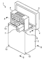
- FIG. 1 is a perspective view showing an example of a heat insulating container 1 according to Embodiment 1 of the present invention.
- the heat insulating container 1 includes a container 2, a lid 3 and a storage shelf 4.
- the container 2 has a box shape.
- FIG. 1 shows an example in which the outer shape of the container 2 is a rectangular parallelepiped shape.
- the outer shape of the container 2 is not limited to the example shown in FIG.
- the outer shape of the container 2 may be a cylindrical shape.
- the lid 3 closes the opening formed in the container 2.
- the lid 3 is detachable from the container 2, for example. When the lid 3 is attached to the container 2, the space formed inside the container 2 is sealed.
- FIG. 1 shows an example in which two storage shelves 4 are stored in a container 2.
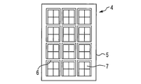
- FIG. 2 is a diagram showing an example of the storage shelf 4.
- the storage shelf 4 includes, for example, a frame 5 and a partition 6.
- the outer shape of the frame 5 is matched to the inner shape of the container 2. 1 and 2 show an example in which the outer shape of the frame 5 viewed from the front is a quadrangle.
- the partition 6 is fixed to the frame 5.
- the space formed inside the frame 5 is partitioned by a partition 6. 1 and 2 show an example in which the partition 6 has a lattice shape.
- the article 7 is arranged in the space partitioned by the partition 6.
- the heat insulating container 1 is used to keep the temperature of the article 7 constant.
- article 7 contains a vaccine preparation
- the vaccine preparation is placed, for example, in a dedicated container.
- the container containing the vaccine preparation is wrapped in a cushioning material or the like.
- article 7 includes a vaccine formulation, a container and a cushioning material.
- the container for the vaccine formulation may be part of a syringe that is used in performing the vaccination.
- an article 7 containing a vaccine preparation is put in a heat insulating container 1 at a base or the like, and is carried to a vaccine inoculation site by a motorbike or the like.
- the temperature at which the vaccine formulation is stored must be, for example, 2 ° C to 8 ° C.
- the article 7 is not limited to the one containing the vaccine preparation. You may utilize the heat insulation container 1 in a cold chain. In such a case, the article 7 may include fresh food, frozen food, medicine, electronic parts, or the like.
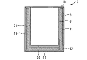
- FIG. 3 is a view showing a cross section of the container 2.
- FIG. 3 is a view corresponding to the AA cross section shown in FIG.
- the container 2 includes, for example, an outer case 8, an inner case 9, a closing body 10, a vacuum heat insulating material 11, and a foam heat insulating material 12.
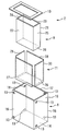
- FIG. 4 is an exploded perspective view of the container 2. In FIG. 4, illustration of the foam heat insulating material 12 is omitted.
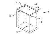
- the outer case 8 is box-shaped. The opening of the outer case 8 faces upward.
- a through hole 13 is formed in the outer case 8.
- FIG. 4 shows an example in which eight through holes 13 are formed in the outer case 8. The number of through holes 13 is not limited to the example shown in FIG. For example, only one through hole 13 may be formed.
- the through hole 13 is a hole into which the foam heat insulating material 12 is injected when the container 2 is manufactured.
- the outer case 8 includes a flat plate 14 and a cylinder 15.
- the cylinder 15 is provided on the edge of the flat plate 14.
- the cylinder 15 is disposed so as to extend upward from the edge of the flat plate 14.
- the flat plate 14 has a quadrangular shape.
- the flat plate 14 has a rectangular shape.
- the cross section of the cylinder 15 parallel to the flat plate 14 is rectangular.
- the cylinder 15 is provided at the edge of the flat plate 14 at the lower end.
- the cylinder 15 includes a flat plate 16, a flat plate 17, a flat plate 18, and a flat plate 19, for example.
- the flat plate 17 faces the flat plate 16.
- the flat plate 17 is parallel to the flat plate 16.
- the flat plate 18 is provided between the flat plate 16 and the flat plate 17.
- the flat plate 18 is orthogonal to the flat plate 16.
- the flat plate 19 is provided between the flat plate 16 and the flat plate 17.
- the flat plate 19 faces the flat plate 18.
- the flat plate 19 is parallel to the flat plate 18.
- the flat plate 19 is orthogonal to the flat plate 16.
- the inner case 9 is box-shaped.
- the inner case 9 is disposed inside the outer case 8.
- the opening of the inner case 9 faces upward.
- the inner case 9 includes a flat plate 20 and a cylindrical body 21.
- the flat plate 20 faces the flat plate 14.
- the flat plate 20 is parallel to the flat plate 14.
- the cylinder 21 is provided on the edge of the flat plate 20.
- the cylindrical body 21 is disposed so as to extend upward from the edge of the flat plate 20.
- the cylinder body 21 is disposed inside the cylinder body 15.
- the flat plate 20 has a quadrangular shape. Specifically, the flat plate 20 has a rectangular shape.
- the cross section of the cylindrical body 21 parallel to the flat plate 20 is rectangular.
- the cylindrical body 21 is provided at the edge of the flat plate 20 at the lower end.
- the cylinder 21 includes a flat plate 22, a flat plate 23, a flat plate 24, and a flat plate 25, for example. If nothing is put in the container 2, the flat plate 23 faces the flat plate 22. In the example shown in FIG. 4, the flat plate 23 is parallel to the flat plate 22. Considering only the outer case 8 and the inner case 9, the flat plate 22 faces the flat plate 16. The flat plate 22 is parallel to the flat plate 16. The flat plate 23 faces the flat plate 17. The flat plate 23 is parallel to the flat plate 17.
- the flat plate 24 is provided between the flat plate 22 and the flat plate 23.
- the flat plate 24 is orthogonal to the flat plate 22.
- the flat plate 25 is provided between the flat plate 22 and the flat plate 23. If nothing is put in the container 2, the flat plate 25 faces the flat plate 24.
- the flat plate 25 is parallel to the flat plate 24.
- the flat plate 25 is orthogonal to the flat plate 22. Considering only the outer case 8 and the inner case 9, the flat plate 24 faces the flat plate 18.
- the flat plate 24 is parallel to the flat plate 18.
- the flat plate 25 faces the flat plate 19.
- the flat plate 25 is parallel to the flat plate 19.
- the closing body 10 is provided between the edge of the outer case 8 and the edge of the inner case 9.
- the closing body 10 closes the gap between the edge of the outer case 8 and the edge of the inner case 9.
- the closing body 10 has a quadrangular annular shape.
- the closing body 10 is provided between the edge of the cylinder body 15 and the edge of the cylinder body 21.
- the closing body 10 closes the gap between the edge of the cylinder 15 and the edge of the cylinder 21.
- the vacuum heat insulating material 11 is disposed between the outer case 8 and the inner case 9.
- the vacuum heat insulating material 11 is disposed at least between the flat plate 14 and the flat plate 20 and between the cylindrical body 15 and the cylindrical body 21.
- the vacuum heat insulating material 11 includes a vacuum heat insulating plate 26, a vacuum heat insulating plate 27, a vacuum heat insulating plate 28, a vacuum heat insulating plate 29, and a vacuum heat insulating plate 30.
- the vacuum heat insulating plate 26 is disposed between the flat plate 14 and the flat plate 20.
- the vacuum heat insulating plate 27 is disposed between the flat plate 16 and the flat plate 22.
- the vacuum heat insulating plate 28 is disposed between the flat plate 17 and the flat plate 23.
- the vacuum heat insulating plate 29 is disposed between the flat plate 18 and the flat plate 24.
- the vacuum heat insulating plate 30 is disposed between the flat plate 19 and the flat plate 25. Therefore, the article 7 placed in the container 2 is surrounded by the vacuum heat insulating material 11 on the lower side and the four sides.
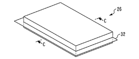
- FIG. 5 is a perspective view showing an example of the vacuum heat insulating plate 26.
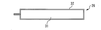
- 6 is a cross-sectional view taken along the line CC of FIG.
- the vacuum heat insulating plate 26 includes glass fibers 31 and a film 32.
- the film 32 is a resin film, for example.
- a plate-like glass fiber 31 covered with a film 32 is a vacuum heat insulating plate 26.
- the glass fiber 31 is covered with the film 32, for example, the inside air is attracted
- the thermal conductivity of the vacuum heat insulating plate 26 is, for example, 0.003 [W / mK].
- the configuration of the vacuum heat insulating plate 27 to the vacuum heat insulating plate 30 is the same as that of the vacuum heat insulating plate 26.
- the foam heat insulating material 12 is filled from the through hole 13 into the space surrounded by the outer case 8, the inner case 9 and the closing body 10 after the outer case 8, the inner case 9 and the closing body 10 are assembled.
- the vacuum heat insulating material 11 is already disposed between the outer case 8 and the inner case 9.
- FIG. 3 shows an example in which the foamed heat insulating material 12 is filled in all the portions other than the vacuum heat insulating material 11 in the space surrounded by the outer case 8, the inner case 9 and the closing body 10.
- a part of the foam heat insulating material 12 is provided between the outer case 8 and the vacuum heat insulating material 11.
- a part of the foam heat insulating material 12 is provided between the inner case 9 and the vacuum heat insulating material 11. A part of the foam heat insulating material 12 is provided between the closing body 10 and the vacuum heat insulating material 11. A part of the foam heat insulating material 12 is provided between adjacent vacuum heat insulating plates.
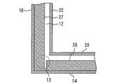
- FIG. 7 is a view showing a part of the BB cross section of FIG.
- the position of the lower through hole 13 formed in the flat plate 19 is indicated by a broken line.
- the edge 26a of the vacuum heat insulating plate 26 faces the vacuum heat insulating plate 27 side.
- the vacuum heat insulating plate 26 is disposed such that a gap with a certain width is provided between the edge 26 a and the vacuum heat insulating plate 27.
- the through hole 13 faces a gap formed between adjacent vacuum heat insulating plates. If the through-hole 13 is formed in such a position, the foam heat insulating material 12 can be easily filled in the gap between the adjacent vacuum heat insulating plates.
- FIG. 8 is a diagram showing an example of a DD cross section of FIG.
- FIG. 8 is a view showing an example of the filled foam heat insulating material 12.
- the foam heat insulating material 12 may be disposed only in a space surrounded by the outer case 8, the inner case 9, and the closing body 10.
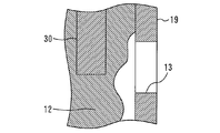
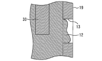
- FIG. 9 is a diagram showing another example of the DD cross section of FIG. As shown in FIG. 9, a part of the foam heat insulating material 12 may be disposed in the through hole 13.
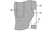
- FIG. 10 is a diagram showing another example of the DD cross section of FIG. As shown in FIG.
- the through hole 13 may be closed by the foam heat insulating material 12.
- the surface of the portion of the foam heat insulating material 12 disposed in the through hole 13 is flush with the surface of the outer case 8.
- FIGS. 8 to 10 show examples of arrangement obtained by injecting the foam heat insulating material 12 from the through hole 13.
- FIG. 7 shows an example in which the foam heat insulating material 12 is provided between the vacuum heat insulating material 11 and the outer case 8 and between the vacuum heat insulating material 11 and the inner case 9.
- the arrangement of the vacuum heat insulating material 11 is not limited to the example shown in FIG. FIGS. 11, 12, and 13 are diagrams illustrating other arrangement examples of the vacuum heat insulating material 11.
- FIG. 11 shows an example in which the vacuum heat insulating material 11 faces the inner case 9.
- the vacuum heat insulating plate 26 faces the flat plate 20 of the inner case 9.
- the vacuum heat insulating plate 26 may be adhered to the flat plate 20.
- the foam heat insulating material 12 is provided between the vacuum heat insulating plate 26 and the flat plate 14 of the outer case 8.
- the vacuum heat insulating plate 27 faces the flat plate 22 of the inner case 9.
- the vacuum heat insulating plate 27 may be adhered to the flat plate 22.
- the foam heat insulating material 12 is provided between the vacuum heat insulating plate 27 and the flat plate 16 of the outer case 8. The same applies to other vacuum heat insulating plates. If it is an example shown in FIG. 11, the quantity of the required vacuum heat insulating material 11 can be reduced.
- FIG. 12 shows an example in which the vacuum heat insulating material 11 faces the outer case 8.
- the vacuum heat insulating plate 26 faces the flat plate 14 of the outer case 8.
- the vacuum heat insulating plate 26 may be adhered to the flat plate 14.
- the foam heat insulating material 12 is provided between the vacuum heat insulating plate 26 and the flat plate 20 of the inner case 9.
- the vacuum heat insulating plate 27 faces the flat plate 16 of the outer case 8.
- the vacuum heat insulating plate 27 may be adhered to the flat plate 16.
- the foam heat insulating material 12 is provided between the vacuum heat insulating plate 27 and the flat plate 22 of the inner case 9. The same applies to other vacuum heat insulating plates.
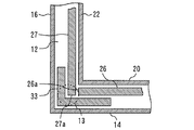
- FIG. 13 shows an example in which some of the vacuum heat insulating materials 11 are arranged in a double manner.
- the vacuum heat insulating material 11 further includes a vacuum heat insulating plate 33 bent into an L shape.
- the vacuum heat insulating plate 26 is disposed such that a gap having a certain width is provided between the edge 26 a and the vacuum heat insulating plate 27.
- the vacuum heat insulating plate 33 is disposed so as to cover the gap from the outer case 8 side.
- the vacuum heat insulating plate 33 is disposed between the edge 26 a of the vacuum heat insulating plate 26, the edge 27 a of the vacuum heat insulating plate 27 closest to the gap and the edge 26 a, and the outer case 8.
- the vacuum heat insulating plate 33 may be disposed so as to cover the gap from the inner case 9 side.
- the vacuum heat insulating plate 33 is disposed between the edge 26 a of the vacuum heat insulating plate 26, the gap and the edge 27 a of the vacuum heat insulating plate 27 and the inner case 9. If it is an example shown in FIG. 13, the heat leak from the clearance gap between the vacuum heat insulation board 26 and the vacuum heat insulation board 27 can be suppressed.
- the vacuum heat insulating material 11 may be disposed in a double manner for other portions adjacent to the vacuum heat insulating plate.
- FIG. 4 shows an example in which the through hole 13 is formed in the cylindrical body 15 of the outer case 8.
- the position where the through hole 13 is formed is not limited to the example shown in FIG. 14, FIG. 15, FIG. 16 and FIG. 17 are diagrams showing other examples of positions where the through holes 13 are formed.
- FIG. 14 shows an example in which a through hole 13 is formed at the center of each flat plate provided in the outer case 8.
- the through hole 13 may be formed in a part of the flat plate provided in the outer case 8.
- the example shown in FIG. 14 is suitable when the vacuum heat insulating material 11 is opposed to the inner case 9 as shown in FIG.
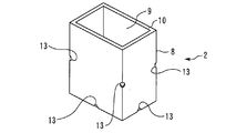
- FIG. 15 shows an example in which through holes 13 are formed at each boundary portion of a flat plate provided in the outer case 8.
- the through hole 13 may be formed at a part of the boundary portion.
- the example shown in FIG. 15 is also suitable when the vacuum heat insulating material 11 is opposed to the inner case 9. In the example shown in FIG. 15, the edge of the vacuum heat insulating plate can be reliably suppressed by the foam heat insulating material 12.
- FIG. 16 shows an example in which the through hole 13 is formed in the closing body 10.
- FIG. 16 shows an example in which through holes 13 are formed at the four corners of the closing body 10.
- the through hole 13 may be further formed in the outer case 8.
- the through hole 13 may be formed in the flat plate 14.
- FIG. 17 shows an example in which the through hole 13 is formed in each flat plate provided in the inner case 9.
- the through hole 13 may be formed in a part of the flat plate provided in the inner case 9.
- the example shown in FIG. 17 is suitable when the vacuum heat insulating material 11 is opposed to the outer case 8 as shown in FIG.
- the through hole 13 may be further formed in the closing body 10.
- the through hole 13 may be further formed in the outer case 8.
- the foam heat insulating material 12 is filled from the through hole 13. For this reason, the foam heat insulating material 12 is visible from the through hole 13. A part of the foam heat insulating material 12 may be disposed in the through hole 13, or the through hole 13 may be blocked by the foam heat insulating material 12.
- FIG. 5 and 6 show an example in which the vacuum heat insulating plate 26 includes a glass fiber 31 and a film 32.
- FIG. The vacuum heat insulation board 26 is not limited to the example shown in FIG.5 and FIG.6.
- the thermal conductivity of the film 32 is higher than the thermal conductivity of the glass fiber 31.
- the thermal conductivity of the film 32 is higher than the thermal conductivity of the foam heat insulating material 12.
- the vacuum heat insulating plate 26 may further include means for suppressing heat transfer through the film 32.
- 18 and 19 are diagrams showing another example of the vacuum heat insulating plate 26.
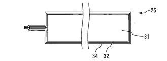
- FIG. 18 shows an example in which the vacuum heat insulating plate 26 further includes a heat insulating sheet 34 in addition to the glass fiber 31 and the film 32.
- the heat insulating sheet 34 is provided on the film 32.
- the heat insulating sheet 34 is disposed outside the film 32 so as to further wrap the film 32 that wraps the glass fiber 31.
- the thermal conductivity of the heat insulating sheet 34 is lower than the thermal conductivity of the film 32. In the example shown in FIG. 18, heat can be prevented from being transmitted through the film 32.
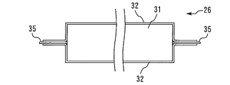
- FIG. 19 shows an example in which the vacuum heat insulating plate 26 further includes a heat insulating film 35 in addition to the glass fiber 31 and the film 32.
- the glass fiber 31 is covered from above and below by two films 32.
- the heat insulating film 35 is disposed between the upper film 32 and the lower film 32. Since the heat insulating film 35 exists, the upper film 32 and the lower film 32 are not in direct contact with each other. For example, the heat conductivity of the heat insulating film 35 is lower than the heat conductivity of the film 32. In the example shown in FIG. 19, heat can be prevented from being transmitted through the film 32.
- the vacuum heat insulating material 11 is supported by the foam heat insulating material 12.
- the foam heat insulating material 12 injected from the through hole 13 is provided both between the vacuum heat insulating material 11 and the outer case 8 and between the vacuum heat insulating material 11 and the inner case 9.
- the foam heat insulating material 12 injected from the through hole 13 is provided between the vacuum heat insulating material 11 and the outer case 8, and the vacuum heat insulating material 11 is attached to the inner case 9 by the foam heat insulating material 12. Pressed.
- FIG. 7 the foam heat insulating material 12 injected from the through hole 13 is provided both between the vacuum heat insulating material 11 and the outer case 8 and between the vacuum heat insulating material 11 and the inner case 9.
- the foam heat insulating material 12 injected from the through hole 13 is provided between the vacuum heat insulating material 11 and the outer case 8, and the vacuum heat insulating material 11 is attached to the inner case 9 by the foam heat insulating material 12. Pressed.
- FIG. 7 the foam heat insul
- the foam heat insulating material 12 injected from the through hole 13 is provided between the vacuum heat insulating material 11 and the inner case 9, and the vacuum heat insulating material 11 is pressed against the outer case 8 by the foam heat insulating material 12. .
- the vacuum heat insulating material 11 can be supported in a desired position, and a heat insulation fall can be suppressed.
- the insulated container 1 shown in the present embodiment is suitable when the temperature of the article 7 needs to be strictly controlled, for example, when the article 7 includes a vaccine preparation.
- the lid 3 is also provided with a vacuum heat insulating material like the container 2.
- the lid 3 may have a cooling function. Both the lid 3 having a cooling function and the lid 3 not having a cooling function may be detachable from the container 2.
- the lid 3 is not an essential element for the heat insulating container 1. For example, when the storage shelf 4 is disposed inside the container 2, a part of the storage shelf 4 may have the function of the lid 3.
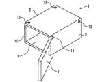
- FIG. 20 is a perspective view showing another example of the heat insulating container 1 according to Embodiment 1 of the present invention.
- FIG. 1 shows an example in which the opening of the container 2 is upward.
- FIG. 20 shows an example in which the opening of the container 2 is sideways.
- the heat insulation container 1 may be used sideways as shown in FIG.
- the heat insulating container according to the present invention is used for keeping the article warm or cold.
Landscapes
- Engineering & Computer Science (AREA)
- Mechanical Engineering (AREA)
- Packages (AREA)
Abstract
L'invention concerne un récipient d'isolation thermique (1) pourvu d'un boîtier extérieur en forme de boîte (8), d'un boîtier intérieur en forme de boîte (9), d'un corps de fermeture (10), d'un matériau d'isolation thermique sous vide (11) et d'un matériau d'isolation thermique en mousse (12). Un trou traversant (13) est formé dans le boîtier extérieur (8). Le matériau d'isolation thermique sous vide (11) est placé entre le boîtier extérieur (8) et le boîtier intérieur (9). Le matériau d'isolation thermique en mousse (12) est situé, par exemple, entre le matériau d'isolation thermique sous vide (11) et le boîtier extérieur (8). Le matériau d'isolation thermique en mousse (12) est visible à travers le trou traversant (13). Le matériau d'isolation thermique sous vide (11) peut être supporté, au moyen du récipient d'isolation thermique (1), dans une position souhaitée et une diminution des propriétés d'isolation thermique peut être supprimée.
Priority Applications (2)
| Application Number | Priority Date | Filing Date | Title |
|---|---|---|---|
| JP2018520235A JP6551605B2 (ja) | 2016-05-31 | 2016-05-31 | 断熱容器 |
| PCT/JP2016/065984 WO2017208331A1 (fr) | 2016-05-31 | 2016-05-31 | Récipient d'isolation thermique |
Applications Claiming Priority (1)
| Application Number | Priority Date | Filing Date | Title |
|---|---|---|---|
| PCT/JP2016/065984 WO2017208331A1 (fr) | 2016-05-31 | 2016-05-31 | Récipient d'isolation thermique |
Publications (1)
| Publication Number | Publication Date |
|---|---|
| WO2017208331A1 true WO2017208331A1 (fr) | 2017-12-07 |
Family
ID=60479210
Family Applications (1)
| Application Number | Title | Priority Date | Filing Date |
|---|---|---|---|
| PCT/JP2016/065984 Ceased WO2017208331A1 (fr) | 2016-05-31 | 2016-05-31 | Récipient d'isolation thermique |
Country Status (2)
| Country | Link |
|---|---|
| JP (1) | JP6551605B2 (fr) |
| WO (1) | WO2017208331A1 (fr) |
Cited By (1)
| Publication number | Priority date | Publication date | Assignee | Title |
|---|---|---|---|---|
| US12378058B2 (en) | 2015-11-25 | 2025-08-05 | Yeti Coolers, Llc | US CIP: insulating container having vacuum insulated panels and method |
Citations (4)
| Publication number | Priority date | Publication date | Assignee | Title |
|---|---|---|---|---|
| JPS61178870A (ja) * | 1985-01-30 | 1986-08-11 | 川北 弘明 | 保温容器 |
| JP2001165389A (ja) * | 1999-12-10 | 2001-06-22 | Matsushita Refrig Co Ltd | 断熱箱体 |
| JP2015169372A (ja) * | 2014-03-06 | 2015-09-28 | 大日本印刷株式会社 | 断熱容器および断熱容器の製造方法 |
| JP2015168465A (ja) * | 2014-03-06 | 2015-09-28 | 大日本印刷株式会社 | 断熱容器および断熱容器の修理方法 |
Family Cites Families (1)
| Publication number | Priority date | Publication date | Assignee | Title |
|---|---|---|---|---|
| JP2015168765A (ja) * | 2014-03-07 | 2015-09-28 | 第一工業製薬株式会社 | エネルギー線硬化型樹脂組成物 |
-
2016
- 2016-05-31 WO PCT/JP2016/065984 patent/WO2017208331A1/fr not_active Ceased
- 2016-05-31 JP JP2018520235A patent/JP6551605B2/ja not_active Expired - Fee Related
Patent Citations (4)
| Publication number | Priority date | Publication date | Assignee | Title |
|---|---|---|---|---|
| JPS61178870A (ja) * | 1985-01-30 | 1986-08-11 | 川北 弘明 | 保温容器 |
| JP2001165389A (ja) * | 1999-12-10 | 2001-06-22 | Matsushita Refrig Co Ltd | 断熱箱体 |
| JP2015169372A (ja) * | 2014-03-06 | 2015-09-28 | 大日本印刷株式会社 | 断熱容器および断熱容器の製造方法 |
| JP2015168465A (ja) * | 2014-03-06 | 2015-09-28 | 大日本印刷株式会社 | 断熱容器および断熱容器の修理方法 |
Cited By (1)
| Publication number | Priority date | Publication date | Assignee | Title |
|---|---|---|---|---|
| US12378058B2 (en) | 2015-11-25 | 2025-08-05 | Yeti Coolers, Llc | US CIP: insulating container having vacuum insulated panels and method |
Also Published As
| Publication number | Publication date |
|---|---|
| JP6551605B2 (ja) | 2019-07-31 |
| JPWO2017208331A1 (ja) | 2018-09-13 |
Similar Documents
| Publication | Publication Date | Title |
|---|---|---|
| WO2014118821A1 (fr) | Boîtier d'isolation thermique | |
| EP2900568B1 (fr) | Système d'emballage à température garantie à base de convexion | |
| KR200471021Y1 (ko) | 온도 조절이 가능한 박스형 패키징 | |
| JP7378979B2 (ja) | 定温保管容器 | |
| WO1999032374A1 (fr) | Emballage de transport isole | |
| WO2012137878A1 (fr) | Récipient de stockage | |
| JP6420118B2 (ja) | 保冷容器 | |
| JP2018164484A5 (fr) | ||
| JP2023054107A (ja) | 定温容器 | |
| WO2021132619A1 (fr) | Récipient à température constante | |
| JP2020100438A (ja) | 恒温構造体 | |
| KR101176077B1 (ko) | 보냉패널 및 이를 이용한 포장박스 | |
| JP6551605B2 (ja) | 断熱容器 | |
| KR20150000671U (ko) | 온도 조절이 가능한 박스형 패키징 | |
| JP3211437U (ja) | 保冷箱 | |
| JP2015193388A (ja) | 保冷箱 | |
| WO2015063820A1 (fr) | Boîte isolée thermiquement | |
| CN207121008U (zh) | 一种可分隔空间的保温箱 | |
| WO2020105178A1 (fr) | Réfrigérateur | |
| WO2017033731A1 (fr) | Glacière | |
| JP3196828U (ja) | 保冷容器 | |
| JP5934883B2 (ja) | 冷凍庫 | |
| KR102634834B1 (ko) | 냉매팩의 모듈형 연결 구조체 | |
| JP7170297B2 (ja) | 保冷保温容器 | |
| ES2632434T3 (es) | Envase isotérmico, método |
Legal Events
| Date | Code | Title | Description |
|---|---|---|---|
| ENP | Entry into the national phase |
Ref document number: 2018520235 Country of ref document: JP Kind code of ref document: A |
|
| 121 | Ep: the epo has been informed by wipo that ep was designated in this application |
Ref document number: 16903959 Country of ref document: EP Kind code of ref document: A1 |
|
| NENP | Non-entry into the national phase |
Ref country code: DE |
|
| 122 | Ep: pct application non-entry in european phase |
Ref document number: 16903959 Country of ref document: EP Kind code of ref document: A1 |