WO2017208345A1 - Unité extérieure pour climatiseur - Google Patents
Unité extérieure pour climatiseur Download PDFInfo
- Publication number
- WO2017208345A1 WO2017208345A1 PCT/JP2016/066028 JP2016066028W WO2017208345A1 WO 2017208345 A1 WO2017208345 A1 WO 2017208345A1 JP 2016066028 W JP2016066028 W JP 2016066028W WO 2017208345 A1 WO2017208345 A1 WO 2017208345A1
- Authority
- WO
- WIPO (PCT)
- Prior art keywords
- compressor
- fan
- rotation speed
- temperature
- inverter circuit
- Prior art date
- Legal status (The legal status is an assumption and is not a legal conclusion. Google has not performed a legal analysis and makes no representation as to the accuracy of the status listed.)
- Ceased
Links
Images




Classifications
-
- F—MECHANICAL ENGINEERING; LIGHTING; HEATING; WEAPONS; BLASTING
- F24—HEATING; RANGES; VENTILATING
- F24F—AIR-CONDITIONING; AIR-HUMIDIFICATION; VENTILATION; USE OF AIR CURRENTS FOR SCREENING
- F24F11/00—Control or safety arrangements
- F24F11/30—Control or safety arrangements for purposes related to the operation of the system, e.g. for safety or monitoring
-
- F—MECHANICAL ENGINEERING; LIGHTING; HEATING; WEAPONS; BLASTING
- F24—HEATING; RANGES; VENTILATING
- F24F—AIR-CONDITIONING; AIR-HUMIDIFICATION; VENTILATION; USE OF AIR CURRENTS FOR SCREENING
- F24F1/00—Room units for air-conditioning, e.g. separate or self-contained units or units receiving primary air from a central station
- F24F1/06—Separate outdoor units, e.g. outdoor unit to be linked to a separate room comprising a compressor and a heat exchanger
- F24F1/20—Electric components for separate outdoor units
- F24F1/24—Cooling of electric components
-
- F—MECHANICAL ENGINEERING; LIGHTING; HEATING; WEAPONS; BLASTING
- F24—HEATING; RANGES; VENTILATING
- F24F—AIR-CONDITIONING; AIR-HUMIDIFICATION; VENTILATION; USE OF AIR CURRENTS FOR SCREENING
- F24F11/00—Control or safety arrangements
- F24F11/70—Control systems characterised by their outputs; Constructional details thereof
- F24F11/72—Control systems characterised by their outputs; Constructional details thereof for controlling the supply of treated air, e.g. its pressure
- F24F11/74—Control systems characterised by their outputs; Constructional details thereof for controlling the supply of treated air, e.g. its pressure for controlling air flow rate or air velocity
- F24F11/77—Control systems characterised by their outputs; Constructional details thereof for controlling the supply of treated air, e.g. its pressure for controlling air flow rate or air velocity by controlling the speed of ventilators
-
- F—MECHANICAL ENGINEERING; LIGHTING; HEATING; WEAPONS; BLASTING
- F24—HEATING; RANGES; VENTILATING
- F24F—AIR-CONDITIONING; AIR-HUMIDIFICATION; VENTILATION; USE OF AIR CURRENTS FOR SCREENING
- F24F11/00—Control or safety arrangements
- F24F11/70—Control systems characterised by their outputs; Constructional details thereof
- F24F11/80—Control systems characterised by their outputs; Constructional details thereof for controlling the temperature of the supplied air
- F24F11/86—Control systems characterised by their outputs; Constructional details thereof for controlling the temperature of the supplied air by controlling compressors within refrigeration or heat pump circuits
-
- G—PHYSICS
- G05—CONTROLLING; REGULATING
- G05B—CONTROL OR REGULATING SYSTEMS IN GENERAL; FUNCTIONAL ELEMENTS OF SUCH SYSTEMS; MONITORING OR TESTING ARRANGEMENTS FOR SUCH SYSTEMS OR ELEMENTS
- G05B19/00—Program-control systems
- G05B19/02—Program-control systems electric
- G05B19/04—Program control other than numerical control, i.e. in sequence controllers or logic controllers
- G05B19/042—Program control other than numerical control, i.e. in sequence controllers or logic controllers using digital processors
-
- F—MECHANICAL ENGINEERING; LIGHTING; HEATING; WEAPONS; BLASTING
- F24—HEATING; RANGES; VENTILATING
- F24F—AIR-CONDITIONING; AIR-HUMIDIFICATION; VENTILATION; USE OF AIR CURRENTS FOR SCREENING
- F24F1/00—Room units for air-conditioning, e.g. separate or self-contained units or units receiving primary air from a central station
- F24F1/06—Separate outdoor units, e.g. outdoor unit to be linked to a separate room comprising a compressor and a heat exchanger
-
- F—MECHANICAL ENGINEERING; LIGHTING; HEATING; WEAPONS; BLASTING
- F24—HEATING; RANGES; VENTILATING
- F24F—AIR-CONDITIONING; AIR-HUMIDIFICATION; VENTILATION; USE OF AIR CURRENTS FOR SCREENING
- F24F2110/00—Control inputs relating to air properties
- F24F2110/10—Temperature
- F24F2110/12—Temperature of the outside air
-
- F—MECHANICAL ENGINEERING; LIGHTING; HEATING; WEAPONS; BLASTING
- F24—HEATING; RANGES; VENTILATING
- F24F—AIR-CONDITIONING; AIR-HUMIDIFICATION; VENTILATION; USE OF AIR CURRENTS FOR SCREENING
- F24F2110/00—Control inputs relating to air properties
- F24F2110/30—Velocity
-
- F—MECHANICAL ENGINEERING; LIGHTING; HEATING; WEAPONS; BLASTING
- F24—HEATING; RANGES; VENTILATING
- F24F—AIR-CONDITIONING; AIR-HUMIDIFICATION; VENTILATION; USE OF AIR CURRENTS FOR SCREENING
- F24F2140/00—Control inputs relating to system states
- F24F2140/50—Load
-
- G—PHYSICS
- G05—CONTROLLING; REGULATING
- G05B—CONTROL OR REGULATING SYSTEMS IN GENERAL; FUNCTIONAL ELEMENTS OF SUCH SYSTEMS; MONITORING OR TESTING ARRANGEMENTS FOR SUCH SYSTEMS OR ELEMENTS
- G05B2219/00—Program-control systems
- G05B2219/20—Pc systems
- G05B2219/26—Pc applications
- G05B2219/2614—HVAC, heating, ventillation, climate control
-
- Y—GENERAL TAGGING OF NEW TECHNOLOGICAL DEVELOPMENTS; GENERAL TAGGING OF CROSS-SECTIONAL TECHNOLOGIES SPANNING OVER SEVERAL SECTIONS OF THE IPC; TECHNICAL SUBJECTS COVERED BY FORMER USPC CROSS-REFERENCE ART COLLECTIONS [XRACs] AND DIGESTS
- Y02—TECHNOLOGIES OR APPLICATIONS FOR MITIGATION OR ADAPTATION AGAINST CLIMATE CHANGE
- Y02B—CLIMATE CHANGE MITIGATION TECHNOLOGIES RELATED TO BUILDINGS, e.g. HOUSING, HOUSE APPLIANCES OR RELATED END-USER APPLICATIONS
- Y02B30/00—Energy efficient heating, ventilation or air conditioning [HVAC]
- Y02B30/70—Efficient control or regulation technologies, e.g. for control of refrigerant flow, motor or heating
Definitions
- the present invention relates to an outdoor unit of an air conditioner that performs air conditioning.
- the outdoor unit of an air conditioner includes an inverter circuit that converts DC power into three-phase AC power using a plurality of switching elements.
- Such an inverter circuit generates three-phase AC power by sequentially switching the switching elements between on and off, and drives the compressor motor and the cooling fan motor.
- the air conditioner of Patent Document 1 uses the temperature detection value by the thermistor and the current value flowing through the compressor motor to prevent the switching element from being destroyed by heat. I have control.
- Patent Document 1 which is the above-described conventional technology, the air conditioner controls the rotation speed of the cooling fan based on the temperature detection value by the thermistor.
- the thermistor it is difficult for the thermistor to detect a rapid temperature change in a short time.
- the present invention has been made in view of the above, and an object thereof is to obtain an outdoor unit of an air conditioner that can operate while preventing thermal destruction of a switching element.
- an outdoor unit of an air conditioner according to the present invention is a compressor that converts DC power for driving a compressor into pseudo three-phase AC using a plurality of switching elements.
- a drive inverter circuit is provided.
- the outdoor unit of the air conditioner according to the present invention includes a fan rotation number detection unit that detects a fan rotation number of a fan that cools the switching element, and an outside air that detects an outside air temperature at a position where the air conditioner is disposed.
- a temperature detection unit is provided.
- the outdoor unit of the air conditioner of the present invention includes a compressor inverter drive unit that controls the compressor rotation speed of the compressor by controlling the compressor drive inverter circuit. And the said compressor inverter drive part controls the said compressor drive inverter circuit based on the said fan rotation speed and the said external temperature.
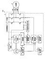
- the figure which shows the structure of the air conditioner which concerns on embodiment The figure which shows the structure of the outdoor unit of the air conditioner which concerns on embodiment
- the figure which shows that the component with which the outdoor unit of embodiment is equipped is a processing circuit
- Flow chart showing processing procedure of fan speed control Sequence diagram showing control processing procedure for compressor drive inverter circuit A diagram for explaining the compressor speed when the fan speed is fixed
- a diagram for explaining the compressor speed when the outside air temperature is constant.
- Embodiment FIG. 1 is a diagram illustrating a configuration of an air conditioner according to an embodiment.
- the air conditioner according to the embodiment includes an outdoor unit 100 that is an outdoor unit, an indoor unit 200, and a refrigerant pipe 300.
- an indoor unit 200 disposed indoors and an outdoor unit 100 disposed outdoor are connected by a refrigerant pipe 300.
- the air conditioner forms one complete refrigeration cycle with the outdoor unit 100, the indoor unit 200, and the refrigerant pipe 300.
- the air conditioner uses a refrigerant that circulates between the indoor unit 200 and the outdoor unit 100 through the refrigerant pipe 300 to perform heat transfer between indoor air and outdoor air that are air-conditioning target spaces. Realizes indoor air conditioning.
- the air conditioner changes the pressure of the refrigerant flowing in the refrigerant pipe 300 by the compressor provided in the outdoor unit 100 and performs air conditioning by heat absorption or heat dissipation of the refrigerant.
- FIG. 2 is a diagram illustrating a configuration of the outdoor unit of the air conditioner according to the embodiment.
- the outdoor unit 100 includes a housing (not shown) that is an outer shell, a fan (not shown) that is housed inside the housing and generates an airflow when rotating, and the compressor 3 that is stored inside the housing. Yes.
- the compressor 3 compresses the refrigerant and circulates the refrigerant.
- the compressor 3 compresses the refrigerant using the current from the compressor drive inverter circuit 2.
- the fan motor 5 rotates the fan, which is a fan, using the current from the fan inverter circuit 4.
- the fan rotates to form an airflow passing through the outdoor heat exchanger.
- the outdoor unit 100 includes a compressor 3, a converter circuit 1 that converts AC power into DC power, a compressor drive inverter circuit 2 that converts DC power into AC power and drives the compressor 3, and DC power as AC And a fan inverter circuit 4 for driving the fan motor 5 by converting into electric power.
- the outdoor unit 100 includes a compressor inverter drive unit 9 that drives the compressor drive inverter circuit 2 by PWM (Pulse Width Modulation) control, and a fan inverter drive unit 6 that drives the fan inverter circuit 4 by PWM control. ing.
- PWM Pulse Width Modulation
- the outdoor unit 100 includes a fan rotation speed detection unit 7 that detects the fan rotation speed of the fan, an outside air temperature detection unit 12 that detects the outside air temperature, and a fin temperature detection unit 11 that detects the fin temperature.
- the outdoor unit 100 includes a compressor current detection unit 10 that detects a current flowing through the compressor drive inverter circuit 2 and a compressor current conversion unit 8 that determines a current flowing through the compressor 3.
- the compressor drive inverter circuit 2 converts DC power for driving the compressor 3 into pseudo three-phase AC using a plurality of switching elements. Specifically, the compressor drive inverter circuit 2 converts the DC power supplied from the converter circuit 1 into AC power using a plurality of switching elements. The compressor drive inverter circuit 2 drives the compressor 3 by the converted pseudo three-phase alternating current. The phases created by the pseudo three-phase alternating current that the compressor drive inverter circuit 2 converts from direct current power are the U phase, the V phase, and the W phase. The compressor drive inverter circuit 2 performs drive control of the compressor 3 based on a PWM signal that is a pulse width modulation signal from the compressor inverter drive unit 9.
- the fan inverter circuit 4 converts the DC power supplied from the converter circuit 1 into AC power using a plurality of switching elements.
- the fan inverter circuit 4 drives the fan motor 5 by the converted pseudo three-phase alternating current.
- the phases created by the pseudo three-phase alternating current that the fan inverter circuit 4 converts from direct current power are the U phase, the V phase, and the W phase.
- the fan inverter circuit 4 performs drive control of the fan motor 5 based on the PWM signal from the fan inverter drive unit 6.
- the fin temperature detection unit 11 is a sensor that detects the fin temperature, which is the temperature of the fin.
- the fin temperature detection unit 11 includes a fin temperature thermistor.
- the fin temperature detector 11 is attached to the fin portion of the heat sink.
- the heat sink is attached to a switching element disposed in the compressor drive inverter circuit 2 or an inverter module in which the compressor drive inverter circuit 2 is disposed.
- the heat sink is for cooling a plurality of switching elements arranged in the compressor drive inverter circuit 2.
- the heat sink attached to the switching element is exposed to the airflow of the fan. For this reason, the airflow by the fan becomes cooling air to the switching element.
- the fin temperature detection unit 11 notifies the detected fan temperature to the fan inverter drive unit 6 and the compressor inverter drive unit 9.
- the outside air temperature detection unit 12 is an outside air temperature detection sensor that detects the outside air temperature.
- the outside temperature detector 12 includes an outside temperature thermistor.
- the outside air temperature detection unit 12 is attached to the suction side surface of the heat exchanger cooling air passage of the outdoor unit 100 of the air conditioner.
- the outside air temperature detection unit 12 detects the ambient temperature of the outdoor unit 100 of the air conditioner. Specifically, the outside air temperature detection unit 12 detects the outside air temperature at the position where the outdoor unit 100 of the air conditioner is disposed.
- the outside air temperature detection unit 12 notifies the compressor inverter drive unit 9 of the detected outside air temperature.
- the compressor current detection unit 10 is connected to wiring in the compressor drive inverter circuit 2.
- the compressor current detection unit 10 detects the voltage value applied to both ends of the shunt resistor in the compressor drive inverter circuit 2 in order to detect the current value flowing through the compressor 3.
- the compressor current detection unit 10 detects a voltage value proportional to the current value flowing through the compressor 3.
- the compressor current detection unit 10 sends the detected voltage value to the compressor current conversion unit 8.
- the compressor current conversion unit 8 converts the voltage value sent from the compressor current detection unit 10 into a compressor current value that is a current value.
- the compressor current conversion unit 8 sends information indicating the compressor current value to the compressor inverter drive unit 9.
- the fan rotation speed detection unit 7 detects the fan rotation speed of the fan based on the information acquired from the fan motor 5.
- the fan rotation speed detection unit 7 sends the detected fan rotation speed to the fan inverter drive unit 6 and the compressor inverter drive unit 9.
- the fan rotation speed detection unit 7 detects the fan rotation speed by counting the pulse signal output from the fan motor 5 every rotation for a certain detection time.
- the fan rotation speed detection unit 7 may detect the rotation speed by any other method.
- the fan inverter drive unit 6 controls the fan rotation number for the fan inverter circuit 4 based on the fan rotation number from the fan rotation number detection unit 7 and the information indicating the fin temperature from the fin temperature detection unit 11. Do.
- the fan inverter drive unit 6 controls the fan speed by controlling the fan rotation speed for the fan inverter circuit 4.
- the compressor inverter drive unit 9 acquires the compressor current value from the compressor current conversion unit 8 and the fan rotation number from the fan rotation number detection unit 7.
- the compressor inverter drive unit 9 acquires information indicating the fin temperature from the fin temperature detection unit 11 and acquires information indicating the outside air temperature from the outside air temperature detection unit 12.
- the compressor inverter drive unit 9 controls the compressor drive inverter circuit 2 based on the compressor current value, the fan speed, the fin temperature, and the outside air temperature.
- the compressor inverter drive unit 9 calculates the amount of current flowing in the current compressor 3 based on the compressor current value.
- the compressor inverter drive unit 9 estimates the driving state of the compressor 3 based on the amount of current that is the calculation result, and controls the compressor rotation speed that is the rotation speed of the compressor 3 based on the estimation result.
- the compressor inverter drive unit 9 of the present embodiment controls the compressor drive inverter circuit 2 so that the compressor speed is changed based on the fan speed and the outside air temperature.
- the compressor inverter drive unit 9 may control the compressor drive inverter circuit 2 so that the compressor speed is changed based on the fan speed or the outside air temperature. Further, the compressor inverter drive unit 9 may control the compressor drive inverter circuit 2 so that the compressor rotational speed is changed based on at least one of the fan rotational speed and the outside air temperature and the fin temperature.
- the outdoor unit 100 may store a threshold value of the current flowing through the compressor drive inverter circuit 2 in advance. In this case, when the current flowing through the compressor drive inverter circuit 2 exceeds the threshold value, the compressor inverter drive unit 9 or the converter circuit 1 of the outdoor unit 100 immediately stops the compressor 3. When the compressor inverter drive unit 9 stops the compressor 3, the compressor inverter drive unit 9 stops the compressor 3 by controlling the compressor drive inverter circuit 2.
- the outdoor unit 100 has an overcurrent protection function that protects the compressor drive inverter circuit 2. Thereby, the outdoor unit 100 can prevent that an overcurrent flows into the compressor drive inverter circuit 2, and a switching element is destroyed.
- FIG. 3 is a diagram illustrating that a component included in the outdoor unit according to the embodiment is a processing circuit.
- the processing circuit 30 is dedicated hardware.
- the processing circuit 30 is a single circuit, a composite circuit, a programmed processor, a parallel programmed processor, an ASIC (Application Specific Integrated Circuit), an FPGA (Field-Programmable Gate Array), or a combination thereof. .
- Some of the components constituting the processing circuit 30 may be dedicated hardware separate from the rest.
- the compressor inverter drive unit 9 of the outdoor unit 100 may be realized by the processing circuit 30. Note that at least one of the fan inverter drive unit 6, the fan rotation speed detection unit 7, the compressor current conversion unit 8, the compressor inverter drive unit 9, and the compressor current detection unit 10 included in the outdoor unit 100 is realized by the processing circuit 30. May be.
- some of the components included in the outdoor unit 100 may be realized by a processor 91 described later that executes a program.
- functions of some of the components included in the outdoor unit 100 are realized by the processor 91 using a memory that is a main memory.
- the case where the control function of the compressor inverter drive unit 9 of the outdoor unit 100 is realized by the processor 91 will be described.
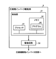
- FIG. 4 is a diagram illustrating a configuration example of a compressor inverter driving unit provided in the outdoor unit according to the embodiment.
- FIG. 4 illustrates a case where some or all of the components included in the compressor inverter drive unit 9 are realized by the control unit 51 and the drive circuit 50.
- the control unit 51 is connected to the drive circuit 50, and the drive circuit 50 is connected to the compressor inverter circuit 2.
- the drive circuit 50 outputs a signal to the compressor inverter circuit 2 in accordance with an instruction from the control unit 51.
- the control unit 51 is realized by using software, and the drive circuit 50 is realized by hardware.
- the control unit 51 includes a processor 91 and a memory 91.
- the processor 91 is a CPU (Central Processing Unit), a processing device, an arithmetic device, a microprocessor, a microcomputer, or a DSP (Digital Signal Processor).
- the processor 91 executes a program 90 stored in the memory 92.
- the function of the compressor inverter drive unit 9 is realized by the control unit 51. That is, the functions of at least some of the constituent elements constituting the compressor inverter drive unit 9 are realized by the processor 91 and the program 90.
- the program 90 is either software, firmware, or a combination of software and firmware. Software or firmware is described by a program 90 and stored in the memory 92.
- the processor 91 reads out and executes the program 90 stored in the memory 92, thereby realizing the functions of the constituent elements constituting the compressor inverter drive unit 9.
- the program 90 executed by the processor 91 is a computer program product having a computer-readable non-transitional recording medium including a plurality of instructions for driving the compressor drive inverter circuit 2 that can be executed by a computer.
- the program 90 executed by the processor 91 causes the computer to execute that the plurality of instructions control the compressor drive inverter circuit 2.
- the program 90 executed by the processor 91 is stored in the memory 92. It can be said that the program 90 stored in the memory 92 causes the computer to execute the procedure or method of the components constituting the compressor drive inverter circuit 2.
- the memory 92 may be a nonvolatile semiconductor memory or a volatile semiconductor memory.
- the memory 92 may be a RAM (Random Access Memory), a ROM (Read Only Memory), a flash memory, an EPROM (Erasable Programmable Read Only Memory), an EEPROM (Electrically Erasable Programmable Memory).
- the memory 92 may be a magnetic disk, a flexible disk, an optical disk, a compact disk, a mini disk, or a DVD (Digital Versatile Disk).
- the functions of a plurality of constituent elements constituting the compressor inverter drive unit 9 may be partially realized by dedicated hardware and the remaining part may be realized by software or firmware. As described above, the functions of the plurality of constituent elements constituting the compressor inverter drive unit 9 can be realized by hardware, software, firmware, or a combination thereof.
- At least one of the fan inverter drive unit 6, the fan rotation speed detection unit 7, the compressor current conversion unit 8, the compressor inverter drive unit 9, and the compressor current detection unit 10 included in the outdoor unit 100 is realized by using the processor 91. May be.
- FIG. 5 is a flowchart showing a processing procedure of fan rotation speed control.
- the fin temperature detection unit 11 detects the temperature of the fin unit.
- the fin temperature detection unit 11 notifies the fan inverter drive unit 6 of the fin temperature that is the detected temperature. Thereby, the fan inverter drive part 6 acquires the information which shows fin temperature.
- the fan inverter drive unit 6 calculates the temperature of the switching element included in the compressor drive inverter circuit 2 based on the information indicating the fin temperature.
- the fan inverter driving unit 6 uses the fin structure, the fin material, the arrangement position of the fin temperature detection unit 11, the switching element structure, or the arrangement environment of the outdoor unit 100, and the element temperature that is the temperature of the switching element from the fin temperature. Is calculated. Thereby, in step S10, the fan inverter drive part 6 acquires element temperature based on fin temperature. As described above, the fan inverter drive unit 6 estimates the element temperature of the current switching element based on the fin temperature sent from the fin temperature detection unit 11.
- the fan inverter drive unit 6 compares the element temperature with the element reference temperature that is the reference temperature of the switching element. In step S20, the fan inverter drive unit 6 determines whether the element temperature is higher than the element reference temperature.
- the fan inverter drive unit 6 determines that the element temperature is equal to or lower than the element reference temperature, that is, when No in step S20, in step S30, the fan inverter drive unit 6 sets the fan rotation speed to the normal fan target. The rotation speed is set to Ffa. Then, the fan inverter drive unit 6 drives the fan inverter circuit 4 so that the fan rotates at the set fan target rotational speed Ffa. Thereby, the fan inverter circuit 4 controls the fan motor 5 so that the fan rotates at the fan target rotation speed Ffa. As a result, when the element temperature is equal to or lower than the element reference temperature, the fan motor 5 rotates the fan at the fan target rotation speed Ffa.
- the fan inverter driving unit 6 determines that the element temperature is higher than the element reference temperature, that is, if Yes in step S20, in step S40, the fan inverter driving unit 6 sets the rotational speed of the fan to a normal value. Is set to a larger fan target speed Ffb.
- the fan target speed Ffb is higher than the normal fan target speed Ffa. That is, the fan target rotational speed Ffb and the normal fan target rotational speed Ffa have a relationship of Ffa ⁇ Ffb.
- the fan inverter drive unit 6 drives the fan inverter circuit 4 so that the fan rotates at the set target fan speed Ffb. Thereby, the fan inverter circuit 4 controls the fan motor 5 so that the fan rotates at the fan target rotation speed Ffb. As a result, when the element temperature is higher than the element reference temperature, the fan motor 5 rotates the fan at the fan target rotation speed Ffb.
- the outdoor unit 100 can increase the amount of cooling air to the switching element as the fan speed is increased.
- the fan inverter driving unit 6 determines that the element temperature of the switching element is higher than the element reference temperature based on the fin temperature
- the fan air speed is increased by increasing the fan speed.
- the fan inverter drive unit 6 determines that the heat generation amount of the switching element is larger than the reference heat generation amount based on the fin temperature
- the fan inverter drive unit 6 increases the cooling air amount by increasing the fan speed.
- the outdoor unit 100 can lower the element temperature of the switching element when the element temperature of the switching element is higher than the element reference temperature.
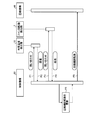
- FIG. 6 is a sequence diagram showing a control processing procedure for the compressor drive inverter circuit. Note that the control mechanism 20 shown in FIG. 6 corresponds to the compressor inverter drive unit 9. Further, the compression mechanism 40 shown in FIG. 6 corresponds to the compressor drive inverter circuit 2.
- the outside air temperature detection unit 12 detects the outside air temperature.
- the control mechanism 20 corresponding to the compressor inverter drive unit 9 inquires the outside air temperature detection unit 12 about the outside air temperature. Thereby, in process P2, the outside temperature detection part 12 notifies the detected outside temperature to the control mechanism 20.
- the control mechanism 20 inquires of the fan rotation speed detection unit 7 about the fan rotation speed. Thereby, in process P4, the fan rotation speed detection unit 7 notifies the control mechanism 20 of the detected fan rotation speed. Thereby, the control mechanism 20 acquires information indicating the outside air temperature and information indicating the fan rotation speed. Note that the outdoor unit 100 may execute either the process P1 or the process P3 first.
- the control mechanism 20 updates the compressor rotational speed that is the set rotational speed for the compressor 3. At this time, the control mechanism 20 estimates the current cooling capacity for the switching element based on the outside air temperature and the fan rotation speed. Then, the control mechanism 20 calculates the compressor speed based on the current cooling capacity for the switching element. The control mechanism 20 updates the compressor rotational speed by setting the calculated compressor rotational speed to the latest compressor rotational speed.
- the cooling air volume by the fan corresponds to the fan speed.
- the cooling capacity to the switching element is affected by the cooling air volume and the outside air temperature. Therefore, the control mechanism 20 of the present embodiment calculates the cooling capacity to the current switching element based on the outside air temperature and the fan speed, and calculates the maximum capacity of the compressor 3 based on the calculated cooling capacity. To do.
- the maximum capacity of the compressor 3 is the compressor speed updated in the process P5. After updating the compressor speed, the control mechanism 20 instructs the compressor speed, which is the compressor drive inverter circuit 2, to the compressor speed in process P6.
- the compressor rotation speed will be described.
- the compressor inverter drive unit 9 sets the compressor rotational speed based on the outside air temperature. Further, the compressor inverter drive unit 9 sets the compressor speed based on the fan speed when the outside air temperature is constant.
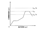
- FIG. 7 is a diagram for explaining the compressor rotational speed when the fan rotational speed is fixed.
- the vertical axis represents the compressor rotational speed indicating the set rotational speed for the compressor 3
- the horizontal axis represents the operation time.
- the compressor rotation speed f max is the compressor rotation speed set by the compressor inverter drive unit 9 when the outside air temperature is the reference outside air temperature T and the fan rotation speed is the fan rotation speed F of the reference rotation speed. Is the maximum value.
- the compressor speed f max is an allowable maximum value among compressor speeds that can be set for the compressor drive inverter circuit 2.
- the compressor rotational speed f max _Ta described later, f max _Tb, f max _Fc , f max _Fd also a maximum allowable value of the compressor speed can be set for the compressor drive inverter circuit 2.
- Compressor speed f max _Ta is the maximum allowed compressor speed when the outside air temperature is outside air temperature Ta
- the compressor rotational speed f max _Tb is compressed when the outside air temperature is ambient temperature Tb This is the maximum allowable machine speed.
- the compressor rotation speed f max — Fc is the allowable maximum value of the compressor rotation speed when the fan rotation speed is the fan rotation speed Fc.
- the compressor rotation speed f max — Fd is the fan rotation speed of the fan rotation speed. This is the allowable maximum value of the compressor speed when Fd.
- the compressor inverter drive unit 9 decreases the compressor rotation speed f max . That is, the compressor inverter drive unit 9 sets the f max _Ta ⁇ compressor speed f max _Ta as the f max.
- the compressor inverter drive unit 9 causes the compressor rotation speed of the compressor 3 to fall below the compressor rotation speed f max that is the reference rotation speed.
- the compressor drive inverter circuit 2 is controlled.
- the compressor inverter drive unit 9 may control the compressor driving inverter circuit 2 to decrease the higher compressor speed f max _Ta outside air temperature is high.
- the rotational speed of the compressor 3 can be kept small, so that the switching element can be cooled with a small cooling capacity.
- the compressor inverter drive unit 9 increases the compressor rotation speed f max . That is, the compressor inverter drive unit 9 sets the compressor speed f max _Tb as the f max ⁇ f max _Tb.
- the compressor inverter drive unit 9 causes the compressor speed of the compressor 3 to rise above the compressor speed f max that is the reference speed.
- the compressor drive inverter circuit 2 is controlled.
- the compressor inverter drive unit 9 may control the compressor driving inverter circuit 2 so that the outside air temperature is higher compressor speed f max _Tb increases low. Accordingly, when the outside air temperature is lowered, the switching element can be cooled with a large cooling capacity even if the rotation speed of the compressor 3 is increased.
- FIG. 8 is a diagram for explaining the compressor rotation speed when the outside air temperature is constant.
- the vertical axis represents the compressor rotational speed indicating the set rotational speed for the compressor 3
- the horizontal axis represents the operation time.
- Compressor rotation speed f max when the outside air temperature is ambient temperature T a is and the fan speed is the reference rotational speed the fan rotational speed F of the reference value, the compressor rotational speed compressor inverter drive unit 9 sets Is the maximum value.
- the compressor inverter drive unit 9 increases the compressor rotation speed f max . That is, the compressor inverter drive unit 9 sets the compressor speed f max _Fc as the f max ⁇ f max _Fc.
- the compressor inverter drive unit 9 causes the compressor rotation speed of the compressor 3 to be higher than the compressor rotation speed f max which is the reference rotation speed.
- the compressor drive inverter circuit 2 is controlled so as to rise.
- the compressor inverter drive unit 9 may control the compressor drive inverter circuit 2 so that the compressor rotation speed f max — Fc increases as the fan rotation speed increases. As a result, when the fan rotation speed increases, the switching element can be cooled with a large cooling capacity even if the rotation speed of the compressor 3 increases.
- the compressor inverter drive unit 9 decreases the compressor rotation speed f max . That is, the compressor inverter drive unit 9 sets the compressor rotation speed f max _Fd such that f max _Fd ⁇ f max .
- the compressor inverter drive unit 9 causes the compressor rotation speed of the compressor 3 to be higher than the compressor rotation speed f max that is the reference rotation speed.
- the compressor drive inverter circuit 2 is controlled so as to be lowered.
- the compressor inverter drive unit 9 so that the fan speed becomes higher compressor speed f max _fd drops smaller, may control the compressor driving inverter circuit 2.
- the rotational speed of the compressor 3 can be kept small, so that the switching element can be cooled with a small cooling capacity.
- the compressor inverter drive unit 9 calculates the cooling capacity for the switching element based on the fan speed and the outside air temperature, and sets the compressor speed corresponding to the cooling capacity for the switching element. Specifically, the compressor inverter drive unit 9 decreases the compressor rotational speed when the cooling capacity to the switching element decreases. Moreover, the compressor inverter drive part 9 raises a compressor rotation speed, when the cooling capability to a switching element goes up.
- the outdoor unit 100 of the air conditioner converts the input AC power into DC power by the converter circuit 1.
- the outdoor unit 100 reconverts the DC power into AC power by the compressor drive inverter circuit 2 and the fan inverter circuit 4, and drives and controls the compressor 3 and the fan motor 5.
- the compressor inverter drive unit 9 acquires the fan rotation number that is information on the cooling air volume from the fan rotation number detection unit 7, and acquires the outside air temperature that is information on the ambient temperature of the outdoor unit 100 from the outside air temperature detection unit 12. To do. And the compressor inverter drive part 9 estimates the cooling capacity of the switching element with which the compressor drive inverter circuit 2 is provided based on fan rotation speed and external temperature. Furthermore, the compressor inverter drive unit 9 sets the compressor rotation speed corresponding to the cooling capacity of the switching element, and controls the compressor drive inverter circuit 2 at the set compressor rotation speed. The compressor speed used when controlling the compressor drive inverter circuit 2 corresponds to the maximum operating range of the compressor 3.
- the compressor inverter drive unit 9 sets the safe operation range defined by the compressor rotation speed before entering the operation range where the switching element of the compressor drive inverter circuit 2 is highly likely to be thermally destroyed. it can. For this reason, the outdoor unit 100 can perform an operation in which the switching element does not cause thermal destruction.
- the compressor inverter drive unit 9 can be operated by increasing the output of the compressor 3 during the heating operation than during the cooling operation. Thereby, the compressor inverter drive unit 9 can widen the operating capacity range of the outdoor unit 100.
- the compressor inverter drive unit 9 sets the compressor rotational speed of the compressor 3 based on the fan rotational speed and the outside air temperature. It becomes possible to operate while preventing thermal destruction of the switching element. Moreover, since the compressor rotation speed of the compressor 3 is set based on the outside air temperature, the outdoor unit 100 of the air conditioner can improve the air conditioning capability.
Landscapes
- Engineering & Computer Science (AREA)
- Chemical & Material Sciences (AREA)
- Combustion & Propulsion (AREA)
- Mechanical Engineering (AREA)
- General Engineering & Computer Science (AREA)
- Physics & Mathematics (AREA)
- Thermal Sciences (AREA)
- Fluid Mechanics (AREA)
- General Physics & Mathematics (AREA)
- Automation & Control Theory (AREA)
- Inverter Devices (AREA)
- Air Conditioning Control Device (AREA)
Abstract
La présente invention concerne une unité extérieure 100 pour un climatiseur comprenant : un circuit d'onduleur d'entraînement de compresseur 2 pour convertir une alimentation en CC destinée à entraîner un compresseur 3 en un CA pseudo-triphasé par une pluralité d'éléments de commutation ; un détecteur de vitesse de rotation de ventilateur 7 pour détecter la vitesse de rotation d'un ventilateur pour refroidir les éléments de commutation ; un détecteur de température d'air extérieur 12 pour détecter la température de l'air extérieur à l'endroit où le climatiseur est installé ; et un dispositif d'entraînement d'onduleur de compresseur 9 pour commander le circuit d'onduleur d'entraînement de compresseur 2 pour commander la vitesse de rotation du compresseur 3. Le dispositif d'entraînement d'onduleur de compresseur 9 commande le circuit d'onduleur d'entraînement de compresseur 2 en fonction de la vitesse de rotation du ventilateur et de la température de l'air extérieur.
Priority Applications (5)
| Application Number | Priority Date | Filing Date | Title |
|---|---|---|---|
| PCT/JP2016/066028 WO2017208345A1 (fr) | 2016-05-31 | 2016-05-31 | Unité extérieure pour climatiseur |
| CN201680085913.5A CN109154450B (zh) | 2016-05-31 | 2016-05-31 | 空调机的室外机 |
| JP2018520246A JP6524346B2 (ja) | 2016-05-31 | 2016-05-31 | 空気調和機の室外機 |
| EP16903973.2A EP3467394B1 (fr) | 2016-05-31 | 2016-05-31 | Unité extérieure pour climatiseur |
| US16/089,095 US10684034B2 (en) | 2016-05-31 | 2016-05-31 | Outdoor unit of air conditioner |
Applications Claiming Priority (1)
| Application Number | Priority Date | Filing Date | Title |
|---|---|---|---|
| PCT/JP2016/066028 WO2017208345A1 (fr) | 2016-05-31 | 2016-05-31 | Unité extérieure pour climatiseur |
Publications (1)
| Publication Number | Publication Date |
|---|---|
| WO2017208345A1 true WO2017208345A1 (fr) | 2017-12-07 |
Family
ID=60478213
Family Applications (1)
| Application Number | Title | Priority Date | Filing Date |
|---|---|---|---|
| PCT/JP2016/066028 Ceased WO2017208345A1 (fr) | 2016-05-31 | 2016-05-31 | Unité extérieure pour climatiseur |
Country Status (5)
| Country | Link |
|---|---|
| US (1) | US10684034B2 (fr) |
| EP (1) | EP3467394B1 (fr) |
| JP (1) | JP6524346B2 (fr) |
| CN (1) | CN109154450B (fr) |
| WO (1) | WO2017208345A1 (fr) |
Cited By (3)
| Publication number | Priority date | Publication date | Assignee | Title |
|---|---|---|---|---|
| WO2020070828A1 (fr) * | 2018-10-03 | 2020-04-09 | 三菱電機株式会社 | Appareil à cycle de réfrigération |
| EP3708920A4 (fr) * | 2018-02-08 | 2021-01-13 | Gree Electric Appliances, Inc. of Zhuhai | Procédé et dispositif de commande de système de climatisation, et système de climatisation associé |
| EP3715737A4 (fr) * | 2018-02-11 | 2021-02-17 | Gree Electric Appliances, Inc. of Zhuhai | Procédé et dispositif de commande d'unité de climatisation, et unité de climatisation associée |
Families Citing this family (6)
| Publication number | Priority date | Publication date | Assignee | Title |
|---|---|---|---|---|
| CN109945397B (zh) * | 2019-03-29 | 2020-12-22 | 广东美的制冷设备有限公司 | 空调器及其防凝露方法和装置 |
| CN112032981B (zh) * | 2020-07-24 | 2021-10-22 | 广东积微科技有限公司 | 空调室内外机通讯电路及空调 |
| CN112032968B (zh) * | 2020-08-27 | 2022-06-03 | 海信(山东)空调有限公司 | 空调器及其控制方法和计算机可读存储介质 |
| CN116324311A (zh) * | 2020-09-01 | 2023-06-23 | 江森自控泰科知识产权控股有限责任合伙公司 | 用于hvac系统的电气壳体 |
| JPWO2023105605A1 (fr) * | 2021-12-07 | 2023-06-15 | ||
| US20260092717A1 (en) * | 2024-10-01 | 2026-04-02 | Airxcel, Inc. | Air conditioner control system and method of use |
Citations (4)
| Publication number | Priority date | Publication date | Assignee | Title |
|---|---|---|---|---|
| WO2003083376A1 (fr) * | 2002-03-29 | 2003-10-09 | Daikin Industries, Ltd. | Climatiseur |
| JP2013137132A (ja) * | 2011-12-28 | 2013-07-11 | Mitsubishi Electric Corp | 空気調和装置 |
| JP2013245922A (ja) * | 2012-05-29 | 2013-12-09 | Mitsubishi Electric Corp | 空気調和装置 |
| JP2015017734A (ja) | 2013-07-10 | 2015-01-29 | 日立アプライアンス株式会社 | 空気調和機 |
Family Cites Families (15)
| Publication number | Priority date | Publication date | Assignee | Title |
|---|---|---|---|---|
| US4257238A (en) * | 1979-09-28 | 1981-03-24 | Borg-Warner Corporation | Microcomputer control for an inverter-driven heat pump |
| JP3356551B2 (ja) * | 1994-07-13 | 2002-12-16 | 東芝キヤリア株式会社 | 空気調和機 |
| JPH1151454A (ja) * | 1997-08-06 | 1999-02-26 | Fujitsu General Ltd | 空気調和機の制御方法 |
| US20060112702A1 (en) * | 2004-05-18 | 2006-06-01 | George Martin | Energy efficient capacity control for an air conditioning system |
| US20060130504A1 (en) * | 2004-12-17 | 2006-06-22 | Agrawal Nityanand J | Method and apparatus for control of a variable speed compressor |
| KR20080083846A (ko) * | 2007-03-13 | 2008-09-19 | 엘지전자 주식회사 | 공기조화기 |
| CN101424412A (zh) * | 2007-10-29 | 2009-05-06 | 乐金电子(天津)电器有限公司 | 带有室外机风扇运转状态感知系统的空调室外机 |
| KR101461559B1 (ko) * | 2007-12-21 | 2014-11-13 | 엘지전자 주식회사 | 공기조화기의 전동기 제어장치 |
| US8011199B1 (en) * | 2010-07-27 | 2011-09-06 | Nordyne Inc. | HVAC control using discrete-speed thermostats and run times |
| CN102345915B (zh) * | 2011-08-02 | 2013-11-27 | 宁波奥克斯电气有限公司 | 直流变频空调的故障运行控制方法 |
| JP6221580B2 (ja) * | 2013-09-30 | 2017-11-01 | 株式会社富士通ゼネラル | 空気調和機 |
| CN104566840B (zh) * | 2013-10-16 | 2018-04-27 | 海尔集团公司 | 冷媒散热装置、安装其的空调及温度控制方法 |
| CN105333659B (zh) * | 2014-08-15 | 2017-12-12 | Tcl空调器(中山)有限公司 | 除湿机压缩机保护控制方法及除湿机 |
| CN104566826B (zh) * | 2014-12-31 | 2017-06-16 | 广东美的制冷设备有限公司 | 变频空调及其压缩机控制方法和装置 |
| CN205174706U (zh) * | 2015-12-11 | 2016-04-20 | 安康学院 | 一种空调散热控制系统 |
-
2016
- 2016-05-31 JP JP2018520246A patent/JP6524346B2/ja not_active Expired - Fee Related
- 2016-05-31 WO PCT/JP2016/066028 patent/WO2017208345A1/fr not_active Ceased
- 2016-05-31 US US16/089,095 patent/US10684034B2/en active Active
- 2016-05-31 EP EP16903973.2A patent/EP3467394B1/fr active Active
- 2016-05-31 CN CN201680085913.5A patent/CN109154450B/zh not_active Expired - Fee Related
Patent Citations (4)
| Publication number | Priority date | Publication date | Assignee | Title |
|---|---|---|---|---|
| WO2003083376A1 (fr) * | 2002-03-29 | 2003-10-09 | Daikin Industries, Ltd. | Climatiseur |
| JP2013137132A (ja) * | 2011-12-28 | 2013-07-11 | Mitsubishi Electric Corp | 空気調和装置 |
| JP2013245922A (ja) * | 2012-05-29 | 2013-12-09 | Mitsubishi Electric Corp | 空気調和装置 |
| JP2015017734A (ja) | 2013-07-10 | 2015-01-29 | 日立アプライアンス株式会社 | 空気調和機 |
Cited By (6)
| Publication number | Priority date | Publication date | Assignee | Title |
|---|---|---|---|---|
| EP3708920A4 (fr) * | 2018-02-08 | 2021-01-13 | Gree Electric Appliances, Inc. of Zhuhai | Procédé et dispositif de commande de système de climatisation, et système de climatisation associé |
| US11585561B2 (en) | 2018-02-08 | 2023-02-21 | Gree Electric Appliances, Inc. Of Zhuhai | Control method and device for air conditioning system and air conditioning system |
| EP3715737A4 (fr) * | 2018-02-11 | 2021-02-17 | Gree Electric Appliances, Inc. of Zhuhai | Procédé et dispositif de commande d'unité de climatisation, et unité de climatisation associée |
| US11408634B2 (en) | 2018-02-11 | 2022-08-09 | Gree Electric Appliances, Inc. Of Zhuhai | Control method and device for controlling air conditioning unit, and air conditioning unit |
| WO2020070828A1 (fr) * | 2018-10-03 | 2020-04-09 | 三菱電機株式会社 | Appareil à cycle de réfrigération |
| JPWO2020070828A1 (ja) * | 2018-10-03 | 2021-04-30 | 三菱電機株式会社 | 冷凍サイクル装置 |
Also Published As
| Publication number | Publication date |
|---|---|
| US20190203962A1 (en) | 2019-07-04 |
| CN109154450B (zh) | 2021-08-06 |
| JP6524346B2 (ja) | 2019-06-05 |
| EP3467394B1 (fr) | 2020-04-22 |
| CN109154450A (zh) | 2019-01-04 |
| JPWO2017208345A1 (ja) | 2018-09-13 |
| EP3467394A4 (fr) | 2019-06-26 |
| EP3467394A1 (fr) | 2019-04-10 |
| US10684034B2 (en) | 2020-06-16 |
Similar Documents
| Publication | Publication Date | Title |
|---|---|---|
| JP6524346B2 (ja) | 空気調和機の室外機 | |
| JP5628233B2 (ja) | モータ駆動装置、流体圧縮システム、及び空気調和機 | |
| JP5455431B2 (ja) | インバータ冷却装置およびインバータ冷却方法ならびに冷凍機 | |
| JP6397050B2 (ja) | 空気調和機 | |
| JP5611423B2 (ja) | インバータ冷却装置およびインバータ冷却方法ならびに冷凍機 | |
| KR20100057894A (ko) | 가변 속도 압축기를 가진 냉동 시스템에 대한 파라미터를 계산하는 시스템 및 방법 | |
| JP5486434B2 (ja) | 電力変換装置 | |
| KR101765925B1 (ko) | 차량용 전동압축기의 일체형 인버터 과열방지 방법 | |
| JP6629446B2 (ja) | 除霜判断機器、除霜制御機器及び空気調和機 | |
| KR101652593B1 (ko) | 모터-구동식 압축기 | |
| JP6378997B2 (ja) | 室外機ユニット | |
| JP2020145773A (ja) | モータ駆動制御装置、ファン、およびモータ駆動制御方法 | |
| JPWO2017183070A1 (ja) | 空気調和装置 | |
| JP2015029395A (ja) | 空気調和機 | |
| JP6040066B2 (ja) | ファンモータの駆動制御装置 | |
| JP4294112B2 (ja) | 室外ファンの制御装置 | |
| KR101151955B1 (ko) | 차량의 공기조화장치용 전동식압축기의 제어방법 | |
| JP2533157B2 (ja) | 空気調和機の周波数制御装置 | |
| JP2013152040A (ja) | 冷却コンプレッサ制御装置 | |
| US9790944B2 (en) | Motor-driven compressor with switching element | |
| JP2008128193A (ja) | 電動圧縮機における電動機駆動装置 | |
| CN120917658A (zh) | 电动机驱动装置以及空调机 | |
| JP3632049B2 (ja) | 空気調和機 |
Legal Events
| Date | Code | Title | Description |
|---|---|---|---|
| ENP | Entry into the national phase |
Ref document number: 2018520246 Country of ref document: JP Kind code of ref document: A |
|
| 121 | Ep: the epo has been informed by wipo that ep was designated in this application |
Ref document number: 16903973 Country of ref document: EP Kind code of ref document: A1 |
|
| NENP | Non-entry into the national phase |
Ref country code: DE |
|
| ENP | Entry into the national phase |
Ref document number: 2016903973 Country of ref document: EP Effective date: 20190102 |