WO2017208384A1 - 電力変換装置 - Google Patents
電力変換装置 Download PDFInfo
- Publication number
- WO2017208384A1 WO2017208384A1 PCT/JP2016/066144 JP2016066144W WO2017208384A1 WO 2017208384 A1 WO2017208384 A1 WO 2017208384A1 JP 2016066144 W JP2016066144 W JP 2016066144W WO 2017208384 A1 WO2017208384 A1 WO 2017208384A1
- Authority
- WO
- WIPO (PCT)
- Prior art keywords
- power conversion
- circulation fan
- conversion device
- sealing
- sealed portion
- Prior art date
- Legal status (The legal status is an assumption and is not a legal conclusion. Google has not performed a legal analysis and makes no representation as to the accuracy of the status listed.)
- Ceased
Links
Images


Classifications
-
- H—ELECTRICITY
- H05—ELECTRIC TECHNIQUES NOT OTHERWISE PROVIDED FOR
- H05K—PRINTED CIRCUITS; CASINGS OR CONSTRUCTIONAL DETAILS OF ELECTRIC APPARATUS; MANUFACTURE OF ASSEMBLAGES OF ELECTRICAL COMPONENTS
- H05K7/00—Constructional details common to different types of electric apparatus
- H05K7/20—Modifications to facilitate cooling, ventilating, or heating
- H05K7/2089—Modifications to facilitate cooling, ventilating, or heating for power electronics, e.g. for inverters for controlling motor
- H05K7/20909—Forced ventilation, e.g. on heat dissipaters coupled to components
-
- H—ELECTRICITY
- H02—GENERATION; CONVERSION OR DISTRIBUTION OF ELECTRIC POWER
- H02M—APPARATUS FOR CONVERSION BETWEEN AC AND AC, BETWEEN AC AND DC, OR BETWEEN DC AND DC, AND FOR USE WITH MAINS OR SIMILAR POWER SUPPLY SYSTEMS; CONVERSION OF DC OR AC INPUT POWER INTO SURGE OUTPUT POWER; CONTROL OR REGULATION THEREOF
- H02M7/00—Conversion of AC power input into DC power output; Conversion of DC power input into AC power output
- H02M7/003—Constructional details, e.g. physical layout, assembly, wiring or busbar connections
-
- H—ELECTRICITY
- H02—GENERATION; CONVERSION OR DISTRIBUTION OF ELECTRIC POWER
- H02M—APPARATUS FOR CONVERSION BETWEEN AC AND AC, BETWEEN AC AND DC, OR BETWEEN DC AND DC, AND FOR USE WITH MAINS OR SIMILAR POWER SUPPLY SYSTEMS; CONVERSION OF DC OR AC INPUT POWER INTO SURGE OUTPUT POWER; CONTROL OR REGULATION THEREOF
- H02M7/00—Conversion of AC power input into DC power output; Conversion of DC power input into AC power output
- H02M7/42—Conversion of DC power input into AC power output without possibility of reversal
- H02M7/44—Conversion of DC power input into AC power output without possibility of reversal by static converters
- H02M7/48—Conversion of DC power input into AC power output without possibility of reversal by static converters using discharge tubes with control electrode or semiconductor devices with control electrode
- H02M7/53—Conversion of DC power input into AC power output without possibility of reversal by static converters using discharge tubes with control electrode or semiconductor devices with control electrode using devices of a triode or transistor type requiring continuous application of a control signal
- H02M7/537—Conversion of DC power input into AC power output without possibility of reversal by static converters using discharge tubes with control electrode or semiconductor devices with control electrode using devices of a triode or transistor type requiring continuous application of a control signal using semiconductor devices only, e.g. single switched pulse inverters
- H02M7/5387—Conversion of DC power input into AC power output without possibility of reversal by static converters using discharge tubes with control electrode or semiconductor devices with control electrode using devices of a triode or transistor type requiring continuous application of a control signal using semiconductor devices only, e.g. single switched pulse inverters in a bridge configuration
- H02M7/53871—Conversion of DC power input into AC power output without possibility of reversal by static converters using discharge tubes with control electrode or semiconductor devices with control electrode using devices of a triode or transistor type requiring continuous application of a control signal using semiconductor devices only, e.g. single switched pulse inverters in a bridge configuration with automatic control of output voltage or current
-
- H—ELECTRICITY
- H05—ELECTRIC TECHNIQUES NOT OTHERWISE PROVIDED FOR
- H05K—PRINTED CIRCUITS; CASINGS OR CONSTRUCTIONAL DETAILS OF ELECTRIC APPARATUS; MANUFACTURE OF ASSEMBLAGES OF ELECTRICAL COMPONENTS
- H05K7/00—Constructional details common to different types of electric apparatus
- H05K7/20—Modifications to facilitate cooling, ventilating, or heating
- H05K7/20009—Modifications to facilitate cooling, ventilating, or heating using a gaseous coolant in electronic enclosures
- H05K7/20136—Forced ventilation, e.g. by fans
- H05K7/20154—Heat dissipaters coupled to components
-
- H—ELECTRICITY
- H05—ELECTRIC TECHNIQUES NOT OTHERWISE PROVIDED FOR
- H05K—PRINTED CIRCUITS; CASINGS OR CONSTRUCTIONAL DETAILS OF ELECTRIC APPARATUS; MANUFACTURE OF ASSEMBLAGES OF ELECTRICAL COMPONENTS
- H05K7/00—Constructional details common to different types of electric apparatus
- H05K7/20—Modifications to facilitate cooling, ventilating, or heating
- H05K7/20009—Modifications to facilitate cooling, ventilating, or heating using a gaseous coolant in electronic enclosures
- H05K7/20136—Forced ventilation, e.g. by fans
- H05K7/20172—Fan mounting or fan specifications
-
- H—ELECTRICITY
- H05—ELECTRIC TECHNIQUES NOT OTHERWISE PROVIDED FOR
- H05K—PRINTED CIRCUITS; CASINGS OR CONSTRUCTIONAL DETAILS OF ELECTRIC APPARATUS; MANUFACTURE OF ASSEMBLAGES OF ELECTRICAL COMPONENTS
- H05K7/00—Constructional details common to different types of electric apparatus
- H05K7/20—Modifications to facilitate cooling, ventilating, or heating
- H05K7/20009—Modifications to facilitate cooling, ventilating, or heating using a gaseous coolant in electronic enclosures
- H05K7/20209—Thermal management, e.g. fan control
-
- H—ELECTRICITY
- H05—ELECTRIC TECHNIQUES NOT OTHERWISE PROVIDED FOR
- H05K—PRINTED CIRCUITS; CASINGS OR CONSTRUCTIONAL DETAILS OF ELECTRIC APPARATUS; MANUFACTURE OF ASSEMBLAGES OF ELECTRICAL COMPONENTS
- H05K7/00—Constructional details common to different types of electric apparatus
- H05K7/20—Modifications to facilitate cooling, ventilating, or heating
- H05K7/20845—Modifications to facilitate cooling, ventilating, or heating for automotive electronic casings
- H05K7/20863—Forced ventilation, e.g. on heat dissipaters coupled to components
-
- H—ELECTRICITY
- H05—ELECTRIC TECHNIQUES NOT OTHERWISE PROVIDED FOR
- H05K—PRINTED CIRCUITS; CASINGS OR CONSTRUCTIONAL DETAILS OF ELECTRIC APPARATUS; MANUFACTURE OF ASSEMBLAGES OF ELECTRICAL COMPONENTS
- H05K7/00—Constructional details common to different types of electric apparatus
- H05K7/20—Modifications to facilitate cooling, ventilating, or heating
- H05K7/2089—Modifications to facilitate cooling, ventilating, or heating for power electronics, e.g. for inverters for controlling motor
- H05K7/20909—Forced ventilation, e.g. on heat dissipaters coupled to components
- H05K7/20918—Forced ventilation, e.g. on heat dissipaters coupled to components the components being isolated from air flow, e.g. hollow heat sinks, wind tunnels or funnels
-
- H—ELECTRICITY
- H05—ELECTRIC TECHNIQUES NOT OTHERWISE PROVIDED FOR
- H05K—PRINTED CIRCUITS; CASINGS OR CONSTRUCTIONAL DETAILS OF ELECTRIC APPARATUS; MANUFACTURE OF ASSEMBLAGES OF ELECTRICAL COMPONENTS
- H05K7/00—Constructional details common to different types of electric apparatus
- H05K7/20—Modifications to facilitate cooling, ventilating, or heating
- H05K7/2089—Modifications to facilitate cooling, ventilating, or heating for power electronics, e.g. for inverters for controlling motor
- H05K7/20945—Thermal management, e.g. inverter temperature control
-
- H—ELECTRICITY
- H10—SEMICONDUCTOR DEVICES; ELECTRIC SOLID-STATE DEVICES NOT OTHERWISE PROVIDED FOR
- H10W—GENERIC PACKAGES, INTERCONNECTIONS, CONNECTORS OR OTHER CONSTRUCTIONAL DETAILS OF DEVICES COVERED BY CLASS H10
- H10W40/00—Arrangements for thermal protection or thermal control
- H10W40/40—Arrangements for thermal protection or thermal control involving heat exchange by flowing fluids
- H10W40/43—Arrangements for thermal protection or thermal control involving heat exchange by flowing fluids by flowing gases, e.g. forced air cooling
-
- H—ELECTRICITY
- H02—GENERATION; CONVERSION OR DISTRIBUTION OF ELECTRIC POWER
- H02M—APPARATUS FOR CONVERSION BETWEEN AC AND AC, BETWEEN AC AND DC, OR BETWEEN DC AND DC, AND FOR USE WITH MAINS OR SIMILAR POWER SUPPLY SYSTEMS; CONVERSION OF DC OR AC INPUT POWER INTO SURGE OUTPUT POWER; CONTROL OR REGULATION THEREOF
- H02M3/00—Conversion of DC power input into DC power output
- H02M3/22—Conversion of DC power input into DC power output with intermediate conversion into AC
- H02M3/24—Conversion of DC power input into DC power output with intermediate conversion into AC by static converters
- H02M3/28—Conversion of DC power input into DC power output with intermediate conversion into AC by static converters using discharge tubes with control electrode or semiconductor devices with control electrode to produce the intermediate AC
- H02M3/325—Conversion of DC power input into DC power output with intermediate conversion into AC by static converters using discharge tubes with control electrode or semiconductor devices with control electrode to produce the intermediate AC using devices of a triode or a transistor type requiring continuous application of a control signal
- H02M3/335—Conversion of DC power input into DC power output with intermediate conversion into AC by static converters using discharge tubes with control electrode or semiconductor devices with control electrode to produce the intermediate AC using devices of a triode or a transistor type requiring continuous application of a control signal using semiconductor devices only
- H02M3/33569—Conversion of DC power input into DC power output with intermediate conversion into AC by static converters using discharge tubes with control electrode or semiconductor devices with control electrode to produce the intermediate AC using devices of a triode or a transistor type requiring continuous application of a control signal using semiconductor devices only having several active switching elements
- H02M3/33573—Full-bridge at primary side of an isolation transformer
Definitions
- the present invention relates to a power conversion device including electronic components that are forcibly air-cooled.
- An electric power conversion device that converts electric power acquired from an overhead line and supplies it to an electric motor or in-vehicle equipment is mounted on the roof or under the floor of an electric railway vehicle.
- the power conversion device includes a power conversion unit that converts input power by a switching operation of a semiconductor element and outputs desired AC power. Since the semiconductor element generates heat when performing a switching operation, a fin or a sword-shaped heat sink that dissipates heat transmitted from the semiconductor element is formed. In order to increase the cooling efficiency, the heat sink is provided at a position where it comes into contact with outside air.
- the semiconductor elements that make up the power conversion unit and the electronic components that make up the output control unit that outputs control signals to the power conversion unit are installed inside a housing that does not come into contact with the outside air in order to prevent failure due to dust and moisture. It is done.
- the installation location of each part which comprises a power converter device is determined according to the necessity for cooling, and the necessity for dust prevention and waterproofing.
- a converter, an inverter, and a filter reactor that require forced air cooling and other devices that do not require forced air cooling are housed together in the same casing.
- the In the AC / DC power conversion system, the converter, the inverter, and the filter reactor are installed in the cooling air passage inside the casing, and other devices that do not require forced air cooling are installed outside the cooling air passage.
- the power converter installed under the railcar floor is divided into a plurality of spaces by partition members.
- the present invention has been made in view of the above-described circumstances, and an object thereof is to reduce a difference in temperature rise of each part in the casing.
- a power conversion device of the present invention includes a power conversion unit that converts and outputs input power, a reactor connected to the input side of the power conversion unit, and an electronic component included in the power conversion unit.
- It is a power converter device provided with the control part to control, Comprising: It is comprised by an open part, a 1st sealing part, and a 2nd sealing part. Outside air, which is air outside the power converter, flows into the open portion, and the reactor is accommodated. Outside air does not flow into the first sealed portion adjacent to the open portion, and electronic components are accommodated. Outside air does not flow into the second sealing part adjacent to the first sealing part, and the control part is accommodated.
- the power converter includes at least two ventilation holes formed in a partition wall between the first sealing part and the second sealing part, a circulation fan provided in the at least one ventilation hole, and the first sealing part.
- a heat sink that is provided in the housing to be formed and radiates at least part of the heat transmitted from the electronic component housed in the first sealed portion to the outside air.
- the first sealed portion is formed by forming at least two vent holes in the partition wall between the first sealed portion and the second sealed portion, and providing the circulation fan at the at least one vent port.
- FIG. 1 It is a perspective view of the housing
- FIG. 1 is a perspective view of a casing of a power converter according to an embodiment of the present invention.
- the description of the upper surface of the power conversion device 1 is omitted.
- the inside of the housing of the power conversion device 1 is divided by a partition wall, and the power conversion device 1 is adjacent to the opening portion 10 into which outside air that is air outside the power conversion device 1 flows in, and the opening portion 10 into which outside air does not flow in.
- the first sealing part 20 and the second sealing part 30 adjacent to the first sealing part 20 from which outside air does not flow are configured.
- the adjacent direction between the opening portion 10 and the first sealing portion 20 and the adjacent direction between the first sealing portion 20 and the second sealing portion 30 are the same.
- the power conversion device 1 is attached, for example, under the floor of an electric railway vehicle.
- An inflow port 11 and an outflow port 12 are formed in the casing that forms the opening 10.
- an inflow port 11 and an outflow port 12 are formed on two surfaces facing in a direction orthogonal to the adjacent direction.
- At least two vent holes 22 are formed in the partition wall 21 between the first sealing portion 20 and the second sealing portion 30.
- the at least one ventilation port 22 is provided with a circulation fan described later.
- At least a part of the heat transmitted from the electronic component housed in the first sealing portion 20 is radiated to the outside on the casing forming the first sealing portion 20, that is, the outer surface of the first sealing portion 20.
- a heat sink 23 is provided. In the example of FIG. 1, the heat sink 23 is exposed to the opening 10.
- FIG. 1 is provided in the example of FIG.
- the shape of the heat sink 23 is a fin shape, but any shape of the heat sink 23 can be used, and the shape of the heat sink 23 may be a sword mountain shape.
- the heat sink 23 is formed on the substrate 24 and dissipates heat transmitted from the electronic component provided on the opposite surface of the substrate 24, that is, in the first sealed portion 20.
- the heat sink 23 is exposed to the open portion 10 from the opening formed on the upper surface of the casing of the first sealing portion 20, but the place where the heat sink 23 is provided is limited to the example of FIG. 1. Absent.
- the direction of the power converter 1 can be determined arbitrarily, in the case of the power converter 1 shown in FIG. 1, the facing direction of the inflow port 11 and the outflow port 12 is made to coincide with the traveling direction of the electric railway vehicle. Wind can be introduced into the opening 10.
- FIG. 2 is a diagram illustrating a configuration example of an electric railway vehicle including the power conversion device according to the embodiment.
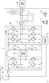
- the power converter 1 converts the power acquired from the overhead line 101 via the current collector 102 and supplies the power to the load device 103 that is an air conditioner or a lighting device connected to the output side.
- the power acquired from the overhead line 101 is input to the power conversion unit 40 via the switch 2 and the input reactor 3.
- the power conversion unit 40 includes a primary circuit 50, a transformer 60, a secondary circuit 70, and a three-phase inverter circuit 80.
- FIG. 1 converts the power acquired from the overhead line 101 via the current collector 102 and supplies the power to the load device 103 that is an air conditioner or a lighting device connected to the output side.
- the power acquired from the overhead line 101 is input to the power conversion unit 40 via the switch 2 and the input reactor 3.
- the power conversion unit 40 includes a primary circuit 50, a transformer 60, a secondary circuit 70, and a three-phase inverter circuit 80.
- the switching elements 52, 53, 54, 55 included in the primary circuit 50 that is an inverter circuit and the switching elements 82, 83, 84, 85, 86, 87 included in the three-phase inverter circuit 80 are IGBTs (Insulated). Gate Bipolar Transistor (insulated gate bipolar transistor), but any semiconductor element can be used.
- the primary circuit 50 converts DC power into high-frequency single-phase AC power.
- the primary circuit 50 has a full bridge configuration, but may have a half bridge configuration or another configuration.
- the transformer 60 is connected to the primary circuit 50 and the secondary circuit 70, and performs power conversion in a state where the primary side and the secondary side are insulated.
- the secondary circuit 70 rectifies the high-frequency AC voltage input from the transformer 60 into a DC voltage, and applies the DC voltage to the capacitor 81 included in the three-phase inverter circuit 80.
- the connection point of the switching elements 52 and 53 and one end of the primary winding of the transformer 60 are connected via a connection conductor, and the connection point of the switching elements 54 and 55 and the other end of the primary winding of the transformer 60 are connected.
- connection conductor One end of the secondary winding of the transformer 60 and the connection point of the diodes 71 and 72 are connected via a connection conductor, and the other end of the secondary winding of the transformer 60 and the connection point of the diodes 73 and 74 are connected. Connected via conductor. In order to prevent the connection conductor from generating heat, a copper thin plate conductor or a litz wire is used as the connection conductor.
- the three-phase inverter circuit 80 performs power conversion and outputs a three-phase AC voltage having a desired frequency and a desired magnitude.
- the control unit 4 controls on / off switching of the switch 2 and switching of the switching elements 52, 53, 54, 55, 82, 83, 84, 85, 86, 87.
- the circulation fan control unit 8 controls the circulation fan 25 so that the circulation fan 25 operates during operation of the power conversion device 1. Power is supplied to the control unit 4, the circulation fan control unit 8, and the circulation fan 25 from the internal power supply of the power conversion device 1.
- a reactor unit 5 composed of an AC reactor provided in each phase
- a capacitor unit 6 composed of an AC capacitor connected to each phase
- a cooling blower 7, and a load device 103 are connected.
- the pulse voltage waveform output from the three-phase inverter circuit 80 is smoothed, and a sine wave AC is obtained.
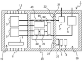
- FIG. 3 and 4 are cross-sectional views of the power converter according to the embodiment.
- 3 is a cross-sectional view taken along the line AA of the power conversion device 1 shown in FIG. 1
- FIG. 4 is a cross-sectional view taken along the line BB of the power conversion device 1 shown in FIG.
- a large amount of high-frequency alternating current flows through the primary circuit 50, the transformer 60, the secondary circuit 70, and the three-phase inverter circuit 80 included in the power conversion unit 40. Therefore, the amount of heat generated is larger than that of other devices. Therefore, the primary circuit 50, the transformer 60, the secondary circuit 70, and the three-phase inverter circuit 80 are accommodated in the first sealed portion 20 where heat generated in the casing is radiated from the casing and the heat sink 23.
- the switch 2, the control unit 4, the capacitor unit 6, and the circulation fan control unit 8 have a smaller calorific value than the devices included in the power conversion unit 40 and may be damaged by dust and moisture. Is accommodated in the hermetically sealed portion 30.
- the AC reactor included in the input reactor 3 and the reactor unit 5 is manufactured by winding a copper or aluminum conductor in a coil shape. During the operation of the power conversion device 1, a large loss occurs due to the resistance of the conductor in the input reactor 3 and the reactor unit 5, so that it is necessary to forcibly cool the input reactor 3 and the reactor unit 5. Therefore, the input reactor 3 and the reactor part 5 are accommodated in the opening part 10.
- the cooling blower 7 is accommodated in the opening 10 in a direction in which air is blown from the inlet 11 toward the outlet 12.
- the connecting conductor that connects the switch 2 and the input reactor 3 and the connecting conductor that connects the reactor unit 5 and the capacitor unit 6 are the partition wall and the first sealed unit between the open unit 10 and the first sealed unit 20. 20 is inserted into a hole (not shown) formed in the partition wall 21 between the second sealing portion 30 and the second sealing portion 30.
- the connection conductor that connects the input reactor 3 and the power conversion unit 40 and the connection conductor that connects the reactor unit 5 and the power conversion unit 40 are formed in the partition wall between the open portion 10 and the first sealed portion 20. Is inserted into a hole (not shown).
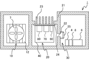
- FIG. A circulation fan 25 is provided in at least one of the at least two vent holes 22 formed in the partition wall 21 between the first sealing portion 20 and the second sealing portion 30.
- the circulation fan control unit 8 operates the circulation fan 25 according to the necessary flow rate of the circulation fan 25 calculated in advance based on the estimated value of the temperature change amount of the first sealing unit 20 and the second sealing unit 30. .
- the circulation fan 25 When the circulation fan 25 is activated, the air in the first sealed part 20 moves to the second sealed part 30, the same amount of air moves from the second sealed part 30 to the first sealed part 20, The air of the 1st sealing part 20 and the 2nd sealing part 30 circulates. By circulating the air in the first sealing part 20 and the second sealing part 30, the difference in the temperature rise between the first sealing part 20 and the second sealing part 30 can be reduced.
- the switching frequency of the primary circuit 50 is about 20 kHz, and the electronic components of the power converter 1 mounted on the electric railway vehicle are connected to the first sealed portion 20 and the second sealed portion 30 as shown in FIGS. 3 and 4.
- the amount of heat radiated to the first sealed portion 20 is about 500 W, whereas the amount of heat generated in the second sealed portion 30 is about 100 W. That is, the temperature rise at the first sealed portion 20 is larger than the temperature rise at the second sealed portion 30.
- the required flow rate of the circulation fan 25 is calculated based on the estimated values of the heat resistant temperature and the temperature change amount of the electronic components housed in the first sealed part 20 and the second sealed part 30.
- the estimated value of the temperature change amount can be calculated from the estimated value of the heat generation amount and the estimated value of the heat dissipation amount.
- the temperature rise of the second sealed portion 30 may be larger than the temperature rise of the first sealed portion 20. Even in that case, the circulation fan 25 is operated to circulate the air between the first sealing portion 20 and the second sealing portion 30, thereby suppressing the temperature rise in the second sealing portion 30. be able to. By operating the circulation fan 25, the difference in temperature rise between the first sealed portion 20 and the second sealed portion 30 can be reduced.
- the connection conductor between the primary circuit 50 and the transformer 60 and the connection conductor between the secondary circuit 70 and the transformer 60 have a frequency of about 20 kHz. Since a current of about 100 A flows, the amount of heat generated by the connecting conductor is large.
- the primary circuit 50, the transformer 60, and the secondary circuit 70 are accommodated in the first sealed part 20, and the connection conductor and the secondary circuit 70 between the primary circuit 50 and the transformer 60 are accommodated. By shortening the length of the connection conductor between the transformer 60 and the transformer 60, the amount of heat generated by the connection conductor due to the skin effect can be reduced.
- the circulation fan 25 is operated according to the required flow rate calculated in advance. However, even if the circulation fan 25 is operated according to the temperature difference between the first sealed portion 20 and the second sealed portion 30. Good.
- the circulation fan control unit 8 acquires the temperature from the temperature sensors provided in the first sealing unit 20 and the second sealing unit 30, and responds to the temperature difference between the first sealing unit 20 and the second sealing unit 30. Then, the required flow rate of the circulation fan 25 is calculated, and the flow rate of the circulation fan 25 is adjusted according to the calculated required flow rate.
- the circulation fan control unit 8 detects the magnitude of the current flowing through the connecting conductor in the first sealed portion 20 and the magnitude of the current flowing through the connecting conductor in the second sealed portion 30, and responds to the difference in the detected value. Then, the required flow rate of the circulation fan 25 may be calculated, and the flow rate of the circulation fan 25 may be adjusted according to the calculated required flow rate.
- vent holes 22 are formed in the partition wall 21 between the first sealing portion 20 and the second sealing portion 30, and at least 1
- the circulation fan 25 at one ventilation port 22
- the embodiment of the present invention is not limited to the above-described embodiment.
- the configuration of the power conversion unit 40 is not limited to the example of FIG. 2, and may be a power conversion circuit including a capacitor and a switching element without a transformer, or a DC-DC converter (Direct-Current-to-Direct- Current Converter) or chopper circuit. You may cool each part of the power converter device 1 with the running wind of an electric railway vehicle, without providing the cooling blower 7.
- the power conversion device 1 may be provided not only under the floor of the electric railway vehicle but also on the roof.
- the number of sealed portions is not limited to two, and the power conversion device 1 may include three or more sealed portions. In that case, at least two or more ventilation openings are formed in each of the partition walls between the sealed portions.
- the structure of the power converter 1 is not limited to the above example.
- 5, 6 and 7 are cross-sectional views of the power converter according to the embodiment.
- the heat sink 23 is exposed to the outside of the power conversion device 1.
- the adjacent direction of the opening portion 10 and the first sealing portion 20 and the adjacent direction of the first sealing portion 20 and the second sealing portion 30 are orthogonal to each other.
- the inlet 11 and the outlet 12 are formed on two adjacent surfaces of the casing forming the opening 10.
Landscapes
- Engineering & Computer Science (AREA)
- Microelectronics & Electronic Packaging (AREA)
- Physics & Mathematics (AREA)
- Thermal Sciences (AREA)
- Power Engineering (AREA)
- Inverter Devices (AREA)
Abstract
電力変換装置(1)の筐体の内部は隔壁で分けられ、電力変換装置(1)は、外気が流入する開放部(10)、開放部(10)に隣接し、外気が内部に流入しない第1の密閉部(20)、および第1の密閉部(20)に隣接し、外気が内部に流入しない第2の密閉部(30)で構成される。第1の密閉部(20)と第2の密閉部(30)との間の隔壁(21)には、少なくとも2つの通風口(22)が形成される。少なくとも1つの通風口(22)に、循環ファン(25)が設けられる。第1の密閉部(20)の外面には、第1の密閉部(20)に収容される電子部品から伝達された熱を放熱する、開放部(10)に露出したヒートシンク(23)が設けられる。
Description
この発明は、強制空冷される電子部品を含む電力変換装置に関する。
電気鉄道車両の屋根上または床下には、架線から取得した電力を変換して電動機または車載機器に供給する電力変換装置が搭載される。電力変換装置は、半導体素子のスイッチング動作によって入力電力を変換して所望の交流電力を出力する電力変換部を有する。半導体素子はスイッチング動作を行う際に発熱するため、半導体素子から伝達された熱を放熱するフィンまたは剣山状のヒートシンクが形成される。冷却効率を高めるため、ヒートシンクは、外気に触れる位置に設けられる。一方、電力変換部を構成する半導体素子および電力変換部に制御信号を出力する出力制御部を構成する電子部品は、粉塵および水分による故障を防止するため、外気に触れない筐体の内部に設けられる。このように、電力変換装置を構成する各部品の設置場所は、冷却の必要性ならびに防塵および防水の必要性に応じて決定される。
特許文献1に開示される交直電車用電力変換システムにおいては、強制空冷を必要とするコンバータ、インバータ、およびフィルタリアクトル、および強制空冷を必要としない他の機器が併せて同一の筐体に収納される。該交直電車用電力変換システムにおいては、コンバータ、インバータ、およびフィルタリアクトルは、筐体内部の冷却風通路に設置され、強制空冷を必要としない他の機器は冷却風通路の外部に設置される。特許文献2に開示される鉄道車両用床下装置のように、鉄道車両の床下に設置される電力変換装置は、筐体内部が仕切り部材によって複数の空間に分けられている。
特許文献1に開示される交直電車用電力変換システムにおいては、強制空冷の対象である機器は十分に冷却されるが、冷却風通路の外部に設置される他の機器が十分に冷却されない場合がある。特許文献2に開示される鉄道車両用床下装置のように、筐体内部が複数の空間に分けられている場合には、筐体の中心に近い空間の温度上昇が、他の空間の温度上昇と比べて大きくなる場合がある。筐体内の一部の温度上昇が他の部分の温度上昇と比べて高くなると、該一部に格納されている電子機器の性能に影響がでる場合がある。
本発明は上述の事情に鑑みてなされたものであり、筐体内の各部の温度上昇の差を低減することが目的である。
上記目的を達成するために、本発明の電力変換装置は、入力電力を変換して出力する電力変換部、電力変換部の入力側に接続されるリアクトル、および電力変換部に含まれる電子部品を制御する制御部を備える電力変換装置であって、開放部と、第1の密閉部と、第2の密閉部とで構成される。開放部には電力変換装置の外部の空気である外気が流入し、リアクトルが収容される。開放部に隣接する第1の密閉部には外気が流入せず、電子部品が収容される。第1の密閉部に隣接する第2の密閉部には外気が流入せず、制御部が収容される。電力変換装置は、第1の密閉部と第2の密閉部との間の隔壁に形成される少なくとも2つの通風口と、少なくとも1つの通風口に設けられる循環ファンと、第1の密閉部を形成する筐体に設けられ、第1の密閉部に収容される電子部品から伝達された熱の少なくとも一部を外気に放熱するヒートシンクと、を備える。
本発明によれば、第1の密閉部と第2の密閉部との間の隔壁に少なくとも2つの通風口を形成し、少なくとも1つの通風口に循環ファンを設けることで、第1の密閉部および第2の密閉部の温度上昇の差を低減することが可能である。
以下、本発明の実施の形態について図面を参照して詳細に説明する。なお図中、同一または同等の部分には同一の符号を付す。
図1は、本発明の実施の形態に係る電力変換装置の筐体の斜視図である。図1においては、電力変換装置1の上面の記載を省略した。電力変換装置1の筐体の内部は隔壁で分けられ、電力変換装置1は、電力変換装置1の外部の空気である外気が流入する開放部10、外気が流入しない、開放部10に隣接する第1の密閉部20、および外気が流入しない第1の密閉部20に隣接する第2の密閉部30で構成される。図1に示す電力変換装置1においては、開放部10と第1の密閉部20との隣接方向、および第1の密閉部20と第2の密閉部30との隣接方向が一致する。電力変換装置1は、例えば、電気鉄道車両の床下に取り付けられる。
開放部10を形成する筐体に流入口11および流出口12が形成される。図1の例では、上記隣接方向と直交する方向に対向する二面に流入口11および流出口12が形成される。第1の密閉部20と第2の密閉部30との間の隔壁21には、少なくとも2つの通風口22が形成される。少なくとも1つの通風口22に、後述する循環ファンが設けられる。第1の密閉部20を形成する筐体、すなわち第1の密閉部20の外面には、第1の密閉部20に収容される電子部品から伝達された熱の少なくとも一部を外気に放熱するヒートシンク23が設けられる。図1の例では、ヒートシンク23は開放部10に露出する。図1の例では、ヒートシンク23の形状はフィン状であるが、任意の形状のヒートシンク23を用いることができ、ヒートシンク23の形状は剣山状でもよい。ヒートシンク23は基板24に形成され、基板24の反対側の面、すなわち第1の密閉部20の内部に設けられる電子部品から伝達された熱を放熱する。図1の例では、第1の密閉部20の筐体の上面に形成された開口からヒートシンク23が開放部10に露出しているが、ヒートシンク23を設ける場所は、図1の例に限られない。電力変換装置1の向きは任意に定めることができるが、図1に示す電力変換装置1の場合、流入口11および流出口12の対向方向を電気鉄道車両の進行方向と一致させることで、走向風を開放部10に取り入れることが可能である。
図2は、実施の形態に係る電力変換装置を備える電気鉄道車両の構成例を示す図である。電力変換装置1は、集電装置102を介して架線101から取得した電力を変換して、出力側に接続される、空調装置または照明装置である負荷装置103に電力を供給する。架線101から取得した電力は、スイッチ2および入力リアクトル3を介して電力変換部40に入力される。電力変換部40は、一次回路50、変圧器60、二次回路70および三相インバータ回路80を有する。図2の例では、インバータ回路である一次回路50が有するスイッチング素子52,53,54,55および三相インバータ回路80が有するスイッチング素子82,83,84,85,86,87は、IGBT(Insulated Gate Bipolar Transistor:絶縁ゲートバイポーラトランジスタ)であるが、任意の半導体素子を用いることができる。
一次回路50は直流電力を高周波の単相交流電力に変換する。図2の例では、一次回路50は、フルブリッジ構成であるが、ハーフブリッジ構成でもよいし、他の構成でもよい。変圧器60は、一次回路50と二次回路70に接続され、一次側と二次側とを絶縁した状態で電力変換を行う。二次回路70は、変圧器60から入力される高周波交流電圧を直流電圧に整流し、三相インバータ回路80が有するコンデンサ81に直流電圧を印加する。スイッチング素子52,53の接続点と変圧器60の一次巻線の一端とが接続導体を介して接続され、スイッチング素子54,55の接続点と変圧器60の一次巻線の他端とが接続導体を介して接続される。変圧器60の二次巻線の一端とダイオード71,72の接続点とが接続導体を介して接続され、変圧器60の二次巻線の他端とダイオード73,74の接続点とが接続導体を介して接続される。接続導体が発熱するのを抑制するために、接続導体には、銅の薄板状の導体またはリッツ線が用いられる。
三相インバータ回路80は、電力変換を行い、所望の周波数および所望の大きさの三相交流電圧を出力する。制御部4は、スイッチ2のオンオフの切り替え、およびスイッチング素子52,53,54,55,82,83,84,85,86,87の切り替えを制御する。循環ファン制御部8は、電力変換装置1の動作中に循環ファン25が作動するように、循環ファン25を制御する。電力変換装置1が有する内部電源から制御部4、循環ファン制御部8および循環ファン25に電力が供給される。
電力変換部40の出力側には、各相に設けられた交流リアクトルから成るリアクトル部5、各相に接続される交流コンデンサから成るコンデンサ部6、冷却ブロア7、および負荷装置103が接続される。リアクトル部5およびコンデンサ部6で平滑フィルタ回路を構成することで、三相インバータ回路80が出力するパルス電圧波形が平滑化され、正弦波交流が得られる。
電力変換装置1の各部の、図1に示す電力変換装置1の筐体内への設置について説明する。図3および図4は、実施の形態に係る電力変換装置の断面図である。図3は、図1に示す電力変換装置1のA-A線の断面図であり、図4は、図3に示す電力変換装置1のB-B線の断面図である。電力変換部40に含まれる、一次回路50、変圧器60、二次回路70、および三相インバータ回路80には、高周波交流の大電流が流れるため、他の機器に比べて発熱量が大きい。そのため、一次回路50、変圧器60、二次回路70、および三相インバータ回路80は、筐体内で発生した熱が、筐体ならびにヒートシンク23から放熱される、第1の密閉部20に収容される。
スイッチ2、制御部4、コンデンサ部6、および循環ファン制御部8は、上記の電力変換部40に含まれる機器に比べて発熱量が小さく、粉塵および水分により故障することがあるため、第2の密閉部30に収容される。入力リアクトル3、およびリアクトル部5に含まれる交流リアクトルは、銅またはアルミの導体をコイル状に巻き回して製造される。電力変換装置1の動作中は、入力リアクトル3、およびリアクトル部5において導体の抵抗により大きな損失が発生するため、入力リアクトル3、およびリアクトル部5を強制的に空冷する必要がある。そのため、入力リアクトル3、およびリアクトル部5は、開放部10に収容される。冷却ブロア7は、流入口11から流出口12に向かって送風する向きに、開放部10に収容される。
スイッチ2と入力リアクトル3とを接続する接続導体、およびリアクトル部5とコンデンサ部6とを接続する接続導体は、開放部10と第1の密閉部20との間の隔壁および第1の密閉部20と第2の密閉部30との間の隔壁21に形成された孔(図示せず)に挿通される。入力リアクトル3と電力変換部40とを接続する接続導体、およびリアクトル部5と電力変換部40とを接続する接続導体は、開放部10と第1の密閉部20との間の隔壁に形成された孔(図示せず)に挿通される。
第1の密閉部20および第2の密閉部30に収容される機器の発熱量は異なる。第1の密閉部20および第2の密閉部30の容積および表面積は異なるため、第1の密閉部20および第2の密閉部30からの放熱量は異なる。そのため、第1の密閉部20と第2の密閉部30の温度上昇量に差が生じる。第1の密閉部20と第2の密閉部30との間の隔壁21に形成された少なくとも2つの通風口22の内、少なくとも1つに循環ファン25が設けられる。循環ファン制御部8は、第1の密閉部20および第2の密閉部30の温度変化量の推定値に基づいて予め算出された循環ファン25の必要流量に応じて、循環ファン25を作動させる。循環ファン25が作動すると、第1の密閉部20の空気が第2の密閉部30に移動し、同量の空気が第2の密閉部30から第1の密閉部20に移動して、第1の密閉部20および第2の密閉部30の空気が循環する。第1の密閉部20および第2の密閉部30の空気を循環させることで、第1の密閉部20および第2の密閉部30の温度上昇量の差を低減することができる。
一次回路50のスイッチング周波数が20kHz程度であり、電気鉄道車両に搭載される電力変換装置1の電子部品が、図3および図4のように第1の密閉部20および第2の密閉部30に収容される場合、第1の密閉部20へ放熱される熱量が500W程度であるのに対し、第2の密閉部30での発熱量は100W程度である。すなわち、第1の密閉部20での温度上昇が第2の密閉部30での温度上昇に比べて大きい。循環ファン25を作動させて、第1の密閉部20と第2の密閉部30との間で空気を循環させることで、第1の密閉部20での温度上昇を抑制することができる。循環ファン25の必要流量は、第1の密閉部20および第2の密閉部30に収容される電子部品の耐熱温度および温度変化量の推定値に基づいて算出される。温度変化量の推定値は、発熱量の推定値および放熱量の推定値から算出することができる。
第2の密閉部30においては、ヒートシンクが設けられていないため、筐体内で発生した熱は、筐体から放熱される。筐体からの放熱が十分でない場合、第2の密閉部30の温度上昇が、第1の密閉部20の温度上昇に比べて大きくなることがある。その場合においても、循環ファン25を作動させて、第1の密閉部20と第2の密閉部30との間で空気を循環させることで、第2の密閉部30での温度上昇を抑制することができる。循環ファン25を作動させることで、第1の密閉部20および第2の密閉部30の温度上昇の差を低減することができる。
一次回路50のスイッチング周波数が20kHz程度である場合、一次回路50と変圧器60との間の接続導体および二次回路70と変圧器60との間の接続導体には、20kHz程度の周波数の数百A程度の電流が流れるため、接続導体の発熱量が大きい。図3および図4のように、一次回路50、変圧器60および二次回路70を第1の密閉部20に収容し、一次回路50と変圧器60との間の接続導体および二次回路70と変圧器60との間の接続導体の長さを短くすることで、表皮効果による接続導体の発熱量を低減することができる。
上述の例では、予め算出された必要流量に応じて循環ファン25を作動させたが、第1の密閉部20および第2の密閉部30の温度差に応じて循環ファン25を作動させてもよい。循環ファン制御部8は、第1の密閉部20および第2の密閉部30に設けられた温度センサから温度を取得し、第1の密閉部20および第2の密閉部30の温度差に応じて循環ファン25の必要流量を算出し、算出した必要流量に応じて循環ファン25の流量を調節する。循環ファン制御部8は、第1の密閉部20内の接続導体を流れる電流の大きさおよび第2の密閉部30内の接続導体を流れる電流の大きさを検出し、検出値の差に応じて循環ファン25の必要流量を算出し、算出した必要流量に応じて循環ファン25の流量を調節してもよい。
以上説明したとおり、実施の形態に係る電力変換装置1によれば、第1の密閉部20と第2の密閉部30との間の隔壁21に少なくとも2つの通風口22を形成し、少なくとも1つの通風口22に循環ファン25を設けることで、第1の密閉部20および第2の密閉部30の温度上昇の差を低減することが可能である。筐体内の各部の温度上昇の差が低減されるため、一部の電子機器で温度が高くなり過ぎることが抑制され、電力変換装置1の信頼性向上および長寿命化が可能である。
本発明の実施の形態は上述の実施の形態に限られない。電力変換部40の構成は、図2の例に限られず、変圧器を有さず、コンデンサとスイッチング素子から成る電力変換回路でもよいし、DC-DC変換器(Direct-Current-to-Direct-Current Converter)またはチョッパ回路でもよい。冷却ブロア7を設けずに、電気鉄道車両の走行風によって、電力変換装置1の各部を冷却してもよい。電力変換装置1は、電気鉄道車両の床下だけでなく、屋根上に設けられてもよい。密閉部の数は2つに限られず、電力変換装置1は、3以上の密閉部を備えても良い。その場合は、密閉部間の隔壁のそれぞれに少なくとも2つ以上の通風口が形成される。
電力変換装置1の構造は上述の例に限られない。図5、図6および図7は、実施の形態に係る電力変換装置の断面図である。図5に示す電力変換装置1においては、ヒートシンク23は、電力変換装置1の外部に露出する。図6に示す電力変換装置1においては、開放部10と第1の密閉部20との隣接方向、および第1の密閉部20と第2の密閉部30との隣接方向は直交する。図7に示す電力変換装置1においては、開放部10を形成する筐体の内、隣り合った二面に流入口11および流出口12が形成される。
本発明は、本発明の広義の精神と範囲を逸脱することなく、様々な実施の形態及び変形が可能とされるものである。また、上述した実施の形態は、この発明を説明するためのものであり、本発明の範囲を限定するものではない。すなわち、本発明の範囲は、実施の形態ではなく、特許請求の範囲によって示される。そして、特許請求の範囲内及びそれと同等の発明の意義の範囲内で施される様々な変形が、この発明の範囲内とみなされる。
1 電力変換装置、2 スイッチ、3 入力リアクトル、4 制御部、5 リアクトル部、6 コンデンサ部、7 冷却ブロア、8 循環ファン制御部、10 開放部、11 流入口、12 流出口、22 通風口、20 第1の密閉部、21 隔壁、23 ヒートシンク、24 基板、25 循環ファン、30 第2の密閉部、40 電力変換部、50 一次回路、51,81 コンデンサ、52,53,54,55,82,83,84,85,86,87 スイッチング素子、60 変圧器、70 二次回路、71,72,73,74 ダイオード、80 三相インバータ回路、101 架線、102 集電装置、103 負荷装置。
Claims (4)
- 入力電力を変換して出力する電力変換部、前記電力変換部の入力側に接続されるリアクトル、および前記電力変換部に含まれる電子部品を制御する制御部を備える電力変換装置であって、
前記リアクトルを収容し、前記電力変換装置の外部の空気である外気が内部に流入する開放部と、
前記開放部に隣接し、前記電子部品を収容し、前記外気が内部に流入しない第1の密閉部と、
前記第1の密閉部に隣接し、前記制御部を収容し、前記外気が内部に流入しない第2の密閉部と、
を備え、
前記第1の密閉部と前記第2の密閉部との間の隔壁に少なくとも2つの通風口が形成され、
少なくとも1つの前記通風口に設けられる循環ファンと、
前記第1の密閉部を形成する筐体に設けられ、前記第1の密閉部に収容される前記電子部品から伝達された熱の少なくとも一部を前記外気に放熱するヒートシンクと、
を備える電力変換装置。 - 前記第1の密閉部および前記第2の密閉部の温度変化量の推定値に基づいて予め算出された前記循環ファンの必要流量に応じて、前記循環ファンを作動させる循環ファン制御部をさらに備える請求項1に記載の電力変換装置。
- 前記第1の密閉部と前記第2の密閉部の温度差に応じて、前記循環ファンの流量を調節する循環ファン制御部をさらに備える請求項1に記載の電力変換装置。
- 前記開放部を形成する筐体に流入口および流出口が形成され、
前記開放部に収容され、前記流入口から前記流出口に向かう方向に送風する冷却ブロアをさらに備える、
請求項1に記載の電力変換装置。
Priority Applications (4)
| Application Number | Priority Date | Filing Date | Title |
|---|---|---|---|
| JP2018520273A JP6479268B2 (ja) | 2016-06-01 | 2016-06-01 | 電力変換装置 |
| PCT/JP2016/066144 WO2017208384A1 (ja) | 2016-06-01 | 2016-06-01 | 電力変換装置 |
| EP16904009.4A EP3468025B1 (en) | 2016-06-01 | 2016-06-01 | Power conversion device |
| US16/304,007 US10555442B2 (en) | 2016-06-01 | 2016-06-01 | Power conversion device |
Applications Claiming Priority (1)
| Application Number | Priority Date | Filing Date | Title |
|---|---|---|---|
| PCT/JP2016/066144 WO2017208384A1 (ja) | 2016-06-01 | 2016-06-01 | 電力変換装置 |
Publications (1)
| Publication Number | Publication Date |
|---|---|
| WO2017208384A1 true WO2017208384A1 (ja) | 2017-12-07 |
Family
ID=60478134
Family Applications (1)
| Application Number | Title | Priority Date | Filing Date |
|---|---|---|---|
| PCT/JP2016/066144 Ceased WO2017208384A1 (ja) | 2016-06-01 | 2016-06-01 | 電力変換装置 |
Country Status (4)
| Country | Link |
|---|---|
| US (1) | US10555442B2 (ja) |
| EP (1) | EP3468025B1 (ja) |
| JP (1) | JP6479268B2 (ja) |
| WO (1) | WO2017208384A1 (ja) |
Cited By (10)
| Publication number | Priority date | Publication date | Assignee | Title |
|---|---|---|---|---|
| JP2019040968A (ja) * | 2017-08-24 | 2019-03-14 | 株式会社三社電機製作所 | 電気機器 |
| WO2019092800A1 (ja) * | 2017-11-08 | 2019-05-16 | 三菱電機株式会社 | 変圧器および電力変換装置 |
| JP2019134658A (ja) * | 2018-01-30 | 2019-08-08 | エルエス産電株式会社Lsis Co., Ltd. | インバータ及びこの制御方法 |
| JP2019161879A (ja) * | 2018-03-14 | 2019-09-19 | 富士電機株式会社 | 電力変換装置 |
| CN110932571A (zh) * | 2019-12-03 | 2020-03-27 | 西安中车永电电气有限公司 | 一种新型逆变功率单元及其功率电路 |
| WO2020067304A1 (ja) * | 2018-09-27 | 2020-04-02 | 株式会社日立製作所 | 鉄道車両用駆動装置、この艤装方法、当該駆動装置を搭載する鉄道車両、およびこの生産方法 |
| WO2021001997A1 (ja) * | 2019-07-04 | 2021-01-07 | 三菱電機株式会社 | 電気車駆動システム及び電気車制御装置の保護方法 |
| WO2022190325A1 (ja) * | 2021-03-11 | 2022-09-15 | 三菱電機株式会社 | 冷却装置および車載機器 |
| WO2023188043A1 (ja) * | 2022-03-29 | 2023-10-05 | 三菱電機株式会社 | 電力変換装置 |
| JPWO2024084666A1 (ja) * | 2022-10-20 | 2024-04-25 |
Families Citing this family (9)
| Publication number | Priority date | Publication date | Assignee | Title |
|---|---|---|---|---|
| WO2017218614A1 (en) | 2016-06-15 | 2017-12-21 | Hunter Fan Company | Ceiling fan system and electronics housing |
| WO2018020615A1 (ja) * | 2016-07-27 | 2018-02-01 | 三菱電機株式会社 | 電力変換装置 |
| CN110073586A (zh) * | 2016-11-28 | 2019-07-30 | 东芝三菱电机产业系统株式会社 | 电力变换装置 |
| JP6725586B2 (ja) * | 2018-05-18 | 2020-07-22 | 本田技研工業株式会社 | 電力変換装置 |
| JP7093747B2 (ja) * | 2019-06-07 | 2022-06-30 | 本田技研工業株式会社 | 電力制御装置及び駆動ユニット |
| US20210267099A1 (en) * | 2020-02-21 | 2021-08-26 | North American Electric, Inc. | Vortex cooling tunnel in variable frequency drive |
| US12501569B2 (en) * | 2021-06-16 | 2025-12-16 | Mitsubishi Electric Corporation | Electronic device |
| US20240326651A1 (en) * | 2023-03-30 | 2024-10-03 | InductEV, Inc. | System and method for thermal management of an inductive wireless power charger |
| US12568609B2 (en) * | 2023-07-11 | 2026-03-03 | Hamilton Sundstrand Corporation | Thermal management systems for rectifier assemblies |
Citations (5)
| Publication number | Priority date | Publication date | Assignee | Title |
|---|---|---|---|---|
| JPH0213266A (ja) * | 1988-06-29 | 1990-01-17 | Hitachi Ltd | インバータ装置 |
| JPH10210762A (ja) * | 1997-01-24 | 1998-08-07 | Toshiba Corp | インバータ装置 |
| JP2001258263A (ja) * | 2000-03-10 | 2001-09-21 | Toshiba Corp | 鉄道車両用電力変換装置 |
| JP2005001598A (ja) | 2003-06-13 | 2005-01-06 | Toshiba Corp | 交直電車用電力変換システム |
| JP2009096460A (ja) | 2007-09-28 | 2009-05-07 | Toshiba Corp | 鉄道車両用床下装置およびその製造方法 |
Family Cites Families (15)
| Publication number | Priority date | Publication date | Assignee | Title |
|---|---|---|---|---|
| JPH11155257A (ja) * | 1997-11-20 | 1999-06-08 | Toshiba Corp | インバータユニット付きモータ |
| US6144556A (en) * | 1999-03-30 | 2000-11-07 | Lanclos; Kenneth W. | Heat dissipating housing for electronic components |
| US7272008B2 (en) * | 2004-03-09 | 2007-09-18 | Intec, Inc. | Portable power inverter with pass through device |
| ES2377018T3 (es) | 2004-06-24 | 2012-03-21 | Sma Solar Technology Ag | Inversor con una carcasa con componentes eléctricos y/o electrónicos presentando disipadores de calor |
| US7142423B2 (en) * | 2004-10-26 | 2006-11-28 | Comarco Wireless Technologies, Inc. | Power adapter with fan assembly |
| JP5483209B2 (ja) * | 2011-03-30 | 2014-05-07 | 株式会社安川電機 | 電力変換装置 |
| JP2012223032A (ja) * | 2011-04-13 | 2012-11-12 | Yaskawa Electric Corp | 電力変換装置 |
| WO2013145246A1 (ja) * | 2012-03-29 | 2013-10-03 | 富士通株式会社 | モジュール型データセンタとその制御方法 |
| JPWO2014147962A1 (ja) * | 2013-03-19 | 2017-02-16 | 富士電機株式会社 | 磁気部品の冷却構造及びこれを備えた電力変換装置 |
| JP5971403B2 (ja) * | 2013-03-19 | 2016-08-17 | 富士電機株式会社 | 冷却装置及びこれを備えた電力変換装置 |
| KR20150011176A (ko) * | 2013-07-22 | 2015-01-30 | 엘에스산전 주식회사 | 냉각 장치 |
| CN104679163A (zh) * | 2013-11-30 | 2015-06-03 | 鸿富锦精密工业(深圳)有限公司 | 电子设备机箱 |
| DE102014001423A1 (de) | 2014-02-03 | 2015-08-06 | Unify Gmbh & Co. Kg | Belüftungseinrichtung |
| JP2016032367A (ja) * | 2014-07-29 | 2016-03-07 | 株式会社安川電機 | 電力変換装置 |
| US9795067B2 (en) * | 2015-04-03 | 2017-10-17 | Mitsubishi Electric Corporation | Electronic apparatus |
-
2016
- 2016-06-01 EP EP16904009.4A patent/EP3468025B1/en active Active
- 2016-06-01 US US16/304,007 patent/US10555442B2/en active Active
- 2016-06-01 WO PCT/JP2016/066144 patent/WO2017208384A1/ja not_active Ceased
- 2016-06-01 JP JP2018520273A patent/JP6479268B2/ja active Active
Patent Citations (5)
| Publication number | Priority date | Publication date | Assignee | Title |
|---|---|---|---|---|
| JPH0213266A (ja) * | 1988-06-29 | 1990-01-17 | Hitachi Ltd | インバータ装置 |
| JPH10210762A (ja) * | 1997-01-24 | 1998-08-07 | Toshiba Corp | インバータ装置 |
| JP2001258263A (ja) * | 2000-03-10 | 2001-09-21 | Toshiba Corp | 鉄道車両用電力変換装置 |
| JP2005001598A (ja) | 2003-06-13 | 2005-01-06 | Toshiba Corp | 交直電車用電力変換システム |
| JP2009096460A (ja) | 2007-09-28 | 2009-05-07 | Toshiba Corp | 鉄道車両用床下装置およびその製造方法 |
Non-Patent Citations (1)
| Title |
|---|
| See also references of EP3468025A4 |
Cited By (16)
| Publication number | Priority date | Publication date | Assignee | Title |
|---|---|---|---|---|
| JP2019040968A (ja) * | 2017-08-24 | 2019-03-14 | 株式会社三社電機製作所 | 電気機器 |
| WO2019092800A1 (ja) * | 2017-11-08 | 2019-05-16 | 三菱電機株式会社 | 変圧器および電力変換装置 |
| JP2019134658A (ja) * | 2018-01-30 | 2019-08-08 | エルエス産電株式会社Lsis Co., Ltd. | インバータ及びこの制御方法 |
| JP2019161879A (ja) * | 2018-03-14 | 2019-09-19 | 富士電機株式会社 | 電力変換装置 |
| JPWO2020067304A1 (ja) * | 2018-09-27 | 2021-05-20 | 株式会社日立製作所 | 鉄道車両用駆動装置、この艤装方法、当該駆動装置を搭載する鉄道車両、およびこの生産方法 |
| WO2020067304A1 (ja) * | 2018-09-27 | 2020-04-02 | 株式会社日立製作所 | 鉄道車両用駆動装置、この艤装方法、当該駆動装置を搭載する鉄道車両、およびこの生産方法 |
| WO2021001997A1 (ja) * | 2019-07-04 | 2021-01-07 | 三菱電機株式会社 | 電気車駆動システム及び電気車制御装置の保護方法 |
| JPWO2021001997A1 (ja) * | 2019-07-04 | 2021-01-07 | ||
| CN110932571A (zh) * | 2019-12-03 | 2020-03-27 | 西安中车永电电气有限公司 | 一种新型逆变功率单元及其功率电路 |
| WO2022190325A1 (ja) * | 2021-03-11 | 2022-09-15 | 三菱電機株式会社 | 冷却装置および車載機器 |
| US12588170B2 (en) | 2021-03-11 | 2026-03-24 | Mitsubishi Electric Corporation | In-vehicle device including cooling apparatus |
| WO2023188043A1 (ja) * | 2022-03-29 | 2023-10-05 | 三菱電機株式会社 | 電力変換装置 |
| JPWO2023188043A1 (ja) * | 2022-03-29 | 2023-10-05 | ||
| JP7570559B2 (ja) | 2022-03-29 | 2024-10-21 | 三菱電機株式会社 | 電力変換装置 |
| JPWO2024084666A1 (ja) * | 2022-10-20 | 2024-04-25 | ||
| JP7849494B2 (ja) | 2022-10-20 | 2026-04-21 | ファナック株式会社 | ノイズフィルタ |
Also Published As
| Publication number | Publication date |
|---|---|
| JPWO2017208384A1 (ja) | 2018-08-09 |
| EP3468025A1 (en) | 2019-04-10 |
| EP3468025B1 (en) | 2022-01-05 |
| JP6479268B2 (ja) | 2019-03-06 |
| EP3468025A4 (en) | 2019-06-05 |
| US10555442B2 (en) | 2020-02-04 |
| US20190208671A1 (en) | 2019-07-04 |
Similar Documents
| Publication | Publication Date | Title |
|---|---|---|
| JP6479268B2 (ja) | 電力変換装置 | |
| JP6433631B2 (ja) | 電力変換装置 | |
| JP5544255B2 (ja) | 半導体パワーモジュール及び電力変換装置 | |
| JP6161127B2 (ja) | 電力変換装置 | |
| JP5712760B2 (ja) | 誘導加熱調理器 | |
| CN111327208A (zh) | 具散热机制的逆变器装置 | |
| US9960725B2 (en) | Electric compressor | |
| WO2011104909A1 (ja) | 回転電機システム | |
| JP6410972B2 (ja) | 電力変換装置 | |
| JP6074346B2 (ja) | 配電盤装置 | |
| JP2010284033A (ja) | 鉄道車両の電源装置 | |
| KR101726099B1 (ko) | 공기 조화기의 인버터 장치 | |
| JP2015163013A (ja) | 圧縮機制御装置、力率改善回路、電装部品の放熱構造、及び電気機器 | |
| JP5225759B2 (ja) | 機器冷却装置 | |
| JP5468690B2 (ja) | 機器冷却装置 | |
| JP7520259B2 (ja) | 電子機器 | |
| JP2013252006A (ja) | モータ駆動装置及びそれを備えた空気調和機 | |
| JP2012222952A (ja) | 負荷駆動装置 | |
| JP4396626B2 (ja) | 電力変換装置 | |
| JP2021151073A (ja) | 電力変換装置 | |
| JP7310467B2 (ja) | 電力変換装置 | |
| JP2019022300A (ja) | 電源装置 | |
| JP6487119B1 (ja) | 電力変換装置 | |
| JPWO2016194097A1 (ja) | 電力変換装置 | |
| JPWO2019026162A1 (ja) | 電力変換装置 |
Legal Events
| Date | Code | Title | Description |
|---|---|---|---|
| ENP | Entry into the national phase |
Ref document number: 2018520273 Country of ref document: JP Kind code of ref document: A |
|
| NENP | Non-entry into the national phase |
Ref country code: DE |
|
| 121 | Ep: the epo has been informed by wipo that ep was designated in this application |
Ref document number: 16904009 Country of ref document: EP Kind code of ref document: A1 |
|
| ENP | Entry into the national phase |
Ref document number: 2016904009 Country of ref document: EP Effective date: 20190102 |