WO2017208498A1 - Système d'alimentation électrique sans contact et système de transmission électrique sans contact - Google Patents
Système d'alimentation électrique sans contact et système de transmission électrique sans contact Download PDFInfo
- Publication number
- WO2017208498A1 WO2017208498A1 PCT/JP2017/003764 JP2017003764W WO2017208498A1 WO 2017208498 A1 WO2017208498 A1 WO 2017208498A1 JP 2017003764 W JP2017003764 W JP 2017003764W WO 2017208498 A1 WO2017208498 A1 WO 2017208498A1
- Authority
- WO
- WIPO (PCT)
- Prior art keywords
- primary
- power
- control circuit
- measurement value
- target value
- Prior art date
- Legal status (The legal status is an assumption and is not a legal conclusion. Google has not performed a legal analysis and makes no representation as to the accuracy of the status listed.)
- Ceased
Links
Images


Classifications
-
- H—ELECTRICITY
- H02—GENERATION; CONVERSION OR DISTRIBUTION OF ELECTRIC POWER
- H02J—ELECTRIC POWER NETWORKS; CIRCUIT ARRANGEMENTS OR SYSTEMS FOR SUPPLYING OR DISTRIBUTING ELECTRIC POWER; SYSTEMS FOR STORING ELECTRIC ENERGY
- H02J50/00—Circuit arrangements or systems for wireless supply or distribution of electric power
- H02J50/10—Circuit arrangements or systems for wireless supply or distribution of electric power using inductive coupling
- H02J50/12—Circuit arrangements or systems for wireless supply or distribution of electric power using inductive coupling of the resonant type
-
- B—PERFORMING OPERATIONS; TRANSPORTING
- B60—VEHICLES IN GENERAL
- B60L—PROPULSION OF ELECTRICALLY-PROPELLED VEHICLES; SUPPLYING ELECTRIC POWER FOR AUXILIARY EQUIPMENT OF ELECTRICALLY-PROPELLED VEHICLES; ELECTRODYNAMIC BRAKE SYSTEMS FOR VEHICLES IN GENERAL; MAGNETIC SUSPENSION OR LEVITATION FOR VEHICLES; MONITORING OPERATING VARIABLES OF ELECTRICALLY-PROPELLED VEHICLES; ELECTRIC SAFETY DEVICES FOR ELECTRICALLY-PROPELLED VEHICLES
- B60L50/00—Electric propulsion with power supplied within the vehicle
- B60L50/50—Electric propulsion with power supplied within the vehicle using propulsion power supplied by batteries or fuel cells
- B60L50/60—Electric propulsion with power supplied within the vehicle using propulsion power supplied by batteries or fuel cells using power supplied by batteries
-
- B—PERFORMING OPERATIONS; TRANSPORTING
- B60—VEHICLES IN GENERAL
- B60L—PROPULSION OF ELECTRICALLY-PROPELLED VEHICLES; SUPPLYING ELECTRIC POWER FOR AUXILIARY EQUIPMENT OF ELECTRICALLY-PROPELLED VEHICLES; ELECTRODYNAMIC BRAKE SYSTEMS FOR VEHICLES IN GENERAL; MAGNETIC SUSPENSION OR LEVITATION FOR VEHICLES; MONITORING OPERATING VARIABLES OF ELECTRICALLY-PROPELLED VEHICLES; ELECTRIC SAFETY DEVICES FOR ELECTRICALLY-PROPELLED VEHICLES
- B60L53/00—Methods of charging batteries, specially adapted for electric vehicles; Charging stations or on-board charging equipment therefor; Exchange of energy storage elements in electric vehicles
- B60L53/10—Methods of charging batteries, specially adapted for electric vehicles; Charging stations or on-board charging equipment therefor; Exchange of energy storage elements in electric vehicles characterised by the energy transfer between the charging station and the vehicle
- B60L53/12—Inductive energy transfer
- B60L53/122—Circuits or methods for driving the primary coil, e.g. supplying electric power to the coil
-
- B—PERFORMING OPERATIONS; TRANSPORTING
- B60—VEHICLES IN GENERAL
- B60L—PROPULSION OF ELECTRICALLY-PROPELLED VEHICLES; SUPPLYING ELECTRIC POWER FOR AUXILIARY EQUIPMENT OF ELECTRICALLY-PROPELLED VEHICLES; ELECTRODYNAMIC BRAKE SYSTEMS FOR VEHICLES IN GENERAL; MAGNETIC SUSPENSION OR LEVITATION FOR VEHICLES; MONITORING OPERATING VARIABLES OF ELECTRICALLY-PROPELLED VEHICLES; ELECTRIC SAFETY DEVICES FOR ELECTRICALLY-PROPELLED VEHICLES
- B60L53/00—Methods of charging batteries, specially adapted for electric vehicles; Charging stations or on-board charging equipment therefor; Exchange of energy storage elements in electric vehicles
- B60L53/30—Constructional details of charging stations
- B60L53/35—Means for automatic or assisted adjustment of the relative position of charging devices and vehicles
- B60L53/38—Means for automatic or assisted adjustment of the relative position of charging devices and vehicles specially adapted for charging by inductive energy transfer
- B60L53/39—Means for automatic or assisted adjustment of the relative position of charging devices and vehicles specially adapted for charging by inductive energy transfer with position-responsive activation of primary coils
-
- B—PERFORMING OPERATIONS; TRANSPORTING
- B60—VEHICLES IN GENERAL
- B60M—POWER SUPPLY LINES, AND DEVICES ALONG RAILS, FOR ELECTRICALLY- PROPELLED VEHICLES
- B60M7/00—Power lines or rails specially adapted for electrically-propelled vehicles of special types, e.g. suspension tramway, ropeway, underground railway
-
- H—ELECTRICITY
- H02—GENERATION; CONVERSION OR DISTRIBUTION OF ELECTRIC POWER
- H02J—ELECTRIC POWER NETWORKS; CIRCUIT ARRANGEMENTS OR SYSTEMS FOR SUPPLYING OR DISTRIBUTING ELECTRIC POWER; SYSTEMS FOR STORING ELECTRIC ENERGY
- H02J50/00—Circuit arrangements or systems for wireless supply or distribution of electric power
- H02J50/80—Circuit arrangements or systems for wireless supply or distribution of electric power involving the exchange of data, concerning supply or distribution of electric power, between transmitting devices and receiving devices
-
- H—ELECTRICITY
- H02—GENERATION; CONVERSION OR DISTRIBUTION OF ELECTRIC POWER
- H02J—ELECTRIC POWER NETWORKS; CIRCUIT ARRANGEMENTS OR SYSTEMS FOR SUPPLYING OR DISTRIBUTING ELECTRIC POWER; SYSTEMS FOR STORING ELECTRIC ENERGY
- H02J7/00—Circuit arrangements for charging or discharging batteries or for supplying loads from batteries
- H02J7/40—Circuit arrangements for charging or discharging batteries or for supplying loads from batteries characterised by the exchange of charge or discharge related data
-
- H—ELECTRICITY
- H02—GENERATION; CONVERSION OR DISTRIBUTION OF ELECTRIC POWER
- H02J—ELECTRIC POWER NETWORKS; CIRCUIT ARRANGEMENTS OR SYSTEMS FOR SUPPLYING OR DISTRIBUTING ELECTRIC POWER; SYSTEMS FOR STORING ELECTRIC ENERGY
- H02J7/00—Circuit arrangements for charging or discharging batteries or for supplying loads from batteries
- H02J7/40—Circuit arrangements for charging or discharging batteries or for supplying loads from batteries characterised by the exchange of charge or discharge related data
- H02J7/42—Circuit arrangements for charging or discharging batteries or for supplying loads from batteries characterised by the exchange of charge or discharge related data with electronic devices having internal batteries, e.g. mobile phones
-
- H—ELECTRICITY
- H02—GENERATION; CONVERSION OR DISTRIBUTION OF ELECTRIC POWER
- H02J—ELECTRIC POWER NETWORKS; CIRCUIT ARRANGEMENTS OR SYSTEMS FOR SUPPLYING OR DISTRIBUTING ELECTRIC POWER; SYSTEMS FOR STORING ELECTRIC ENERGY
- H02J2207/00—Details of circuit arrangements for charging or discharging batteries or supplying loads from batteries
- H02J2207/20—Charging or discharging characterised by the power electronics converter
-
- Y—GENERAL TAGGING OF NEW TECHNOLOGICAL DEVELOPMENTS; GENERAL TAGGING OF CROSS-SECTIONAL TECHNOLOGIES SPANNING OVER SEVERAL SECTIONS OF THE IPC; TECHNICAL SUBJECTS COVERED BY FORMER USPC CROSS-REFERENCE ART COLLECTIONS [XRACs] AND DIGESTS
- Y02—TECHNOLOGIES OR APPLICATIONS FOR MITIGATION OR ADAPTATION AGAINST CLIMATE CHANGE
- Y02T—CLIMATE CHANGE MITIGATION TECHNOLOGIES RELATED TO TRANSPORTATION
- Y02T10/00—Road transport of goods or passengers
- Y02T10/60—Other road transportation technologies with climate change mitigation effect
- Y02T10/70—Energy storage systems for electromobility, e.g. batteries
-
- Y—GENERAL TAGGING OF NEW TECHNOLOGICAL DEVELOPMENTS; GENERAL TAGGING OF CROSS-SECTIONAL TECHNOLOGIES SPANNING OVER SEVERAL SECTIONS OF THE IPC; TECHNICAL SUBJECTS COVERED BY FORMER USPC CROSS-REFERENCE ART COLLECTIONS [XRACs] AND DIGESTS
- Y02—TECHNOLOGIES OR APPLICATIONS FOR MITIGATION OR ADAPTATION AGAINST CLIMATE CHANGE
- Y02T—CLIMATE CHANGE MITIGATION TECHNOLOGIES RELATED TO TRANSPORTATION
- Y02T10/00—Road transport of goods or passengers
- Y02T10/60—Other road transportation technologies with climate change mitigation effect
- Y02T10/7072—Electromobility specific charging systems or methods for batteries, ultracapacitors, supercapacitors or double-layer capacitors
-
- Y—GENERAL TAGGING OF NEW TECHNOLOGICAL DEVELOPMENTS; GENERAL TAGGING OF CROSS-SECTIONAL TECHNOLOGIES SPANNING OVER SEVERAL SECTIONS OF THE IPC; TECHNICAL SUBJECTS COVERED BY FORMER USPC CROSS-REFERENCE ART COLLECTIONS [XRACs] AND DIGESTS
- Y02—TECHNOLOGIES OR APPLICATIONS FOR MITIGATION OR ADAPTATION AGAINST CLIMATE CHANGE
- Y02T—CLIMATE CHANGE MITIGATION TECHNOLOGIES RELATED TO TRANSPORTATION
- Y02T90/00—Enabling technologies or technologies with a potential or indirect contribution to GHG emissions mitigation
- Y02T90/10—Technologies relating to charging of electric vehicles
- Y02T90/12—Electric charging stations
-
- Y—GENERAL TAGGING OF NEW TECHNOLOGICAL DEVELOPMENTS; GENERAL TAGGING OF CROSS-SECTIONAL TECHNOLOGIES SPANNING OVER SEVERAL SECTIONS OF THE IPC; TECHNICAL SUBJECTS COVERED BY FORMER USPC CROSS-REFERENCE ART COLLECTIONS [XRACs] AND DIGESTS
- Y02—TECHNOLOGIES OR APPLICATIONS FOR MITIGATION OR ADAPTATION AGAINST CLIMATE CHANGE
- Y02T—CLIMATE CHANGE MITIGATION TECHNOLOGIES RELATED TO TRANSPORTATION
- Y02T90/00—Enabling technologies or technologies with a potential or indirect contribution to GHG emissions mitigation
- Y02T90/10—Technologies relating to charging of electric vehicles
- Y02T90/14—Plug-in electric vehicles
Definitions
- the present invention generally relates to a non-contact power supply system and a non-contact power transmission system, and more particularly to a non-contact power supply system and a non-contact power transmission system that perform non-contact power transmission to a power supply target.
- the power supply apparatus includes a power transmission unit, a first acquisition unit, a control unit, a second acquisition unit, and a correction unit.
- the power transmission unit is disposed opposite to the power reception unit of the power receiving side device with a space therebetween.
- a 1st acquisition means acquires the 1st characteristic value which concerns on the electric power supplied to a power transmission part with a 1st period.
- the control means controls the electric power based on the first characteristic value so that the electric power supplied to the power transmission unit approaches the first command value.
- a 2nd acquisition means acquires the 2nd command value transmitted from a power receiving side apparatus, and the 2nd characteristic value concerning electric power received by the power receiving part for every 2nd period. Then, the correcting unit corrects the first command value based on the second command value and the second characteristic value.
- the first command value (primary target value) is corrected based only on the second command value (secondary target value) and the second characteristic value (secondary measurement value). For this reason, the conventional example has a problem that it is difficult to quickly bring the secondary measurement value close to the secondary target value.
- the present invention has been made in view of the above points, and an object of the present invention is to provide a non-contact power feeding system and a non-contact power transmission system in which a secondary measurement value can be easily brought close to a secondary target value.
- the contactless power supply system includes a primary circuit and a primary control circuit.
- the primary circuit supplies primary power to the feeding coil.
- the primary control circuit controls the primary circuit.
- the primary control circuit is configured to acquire a primary measurement value that is a measurement value of the primary power.
- the primary control circuit performs secondary control on a secondary measurement value that is a measurement value of secondary power received by a receiving coil that is electromagnetically coupled to the power supply coil, and a secondary target value that is a target value of the secondary power.
- the primary control circuit is configured to repeatedly execute a control process and an update process alternately.
- the control process is a process of controlling the primary circuit so that the primary measurement value matches a primary target value that is a target value of the primary power.
- the update process is a process for updating the primary target value.
- the update process includes a process of calculating the primary target value based on the transmission efficiency determined by the primary measurement value and the secondary measurement value and the secondary target value.
- a non-contact power transmission system includes the above-described non-contact power feeding system, a power feeding coil, a power receiving coil, and a secondary control circuit.
- the primary power is supplied to the feeding coil.
- the power receiving coil is electromagnetically coupled to the power feeding coil.
- the secondary control circuit is configured to acquire a secondary measurement value that is a measurement value of secondary power supplied to the power receiving coil.
- the secondary control circuit is configured to transmit the secondary measurement value and a secondary target value that is a target value of the secondary power to the primary control circuit.
- FIG. 1A is a block diagram of a contactless power feeding system and a contactless power transmission system according to Embodiment 1 of the present invention.
- FIG. 1B is a flowchart showing the operation of the above non-contact power feeding system.
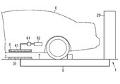
- FIG. 2 is a schematic diagram of an application example of the above non-contact power feeding system.
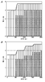
- FIG. 3A is an explanatory diagram of a specific example of the operation of the above non-contact power feeding system.
- FIG. 3B is an explanatory diagram of a specific example of the operation of the contactless power feeding system of the comparative example.
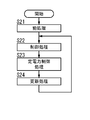
- FIG. 4 is a flowchart showing the operation of the non-contact power feeding system according to the second embodiment of the present invention.
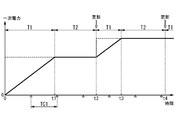
- FIG. 5 is an explanatory diagram of the operation of the above non-contact power feeding system.
- FIG. 6A is an explanatory diagram of control when it is considered that the transmission efficiency cannot be calculated correctly.
- FIG. 6B is an explanatory diagram of control in the above non-contact power feeding system.
- the non-contact electric power feeding system 2 which concerns on Embodiment 1 of this invention is provided with the primary circuit 21 and the primary control circuit 22, as shown to FIG. 1A.
- the primary circuit 21 supplies primary power to the feeding coil 31.
- the primary control circuit 22 controls the primary circuit 21.
- the primary control circuit 22 is configured to acquire a primary measurement value that is a measurement value of primary power.
- the primary control circuit 22 performs secondary control on a secondary measurement value that is a measurement value of the secondary power received by the power receiving coil 41 that is electromagnetically coupled to the power supply coil 31 and a secondary target value that is a target value of the secondary power. It is configured to obtain from the circuit 5.
- the primary control circuit 22 is configured to repeatedly execute a control process and an update process alternately.
- the control process is a process of controlling the primary circuit 21 so that the primary measurement value matches the primary target value that is the target value of the primary power.
- the update process is a process for updating the primary target value.
- the update process includes a process of calculating the primary target value based on the transmission efficiency determined by the primary measurement value and the secondary measurement value and the secondary target value.
- the non-contact power transmission system 1 of the present embodiment includes a non-contact power feeding system 2, a power feeding coil 31, a power receiving coil 41, and a secondary control circuit 5, as shown in FIG. 1A.
- Primary power is supplied to the feeding coil 31.
- the power receiving coil 41 is electromagnetically coupled to the power feeding coil 31.
- the secondary control circuit 5 is configured to acquire a secondary measurement value that is a measurement value of the secondary power supplied to the power receiving coil 41.
- the secondary control circuit 5 is configured to transmit the secondary measurement value and the secondary target value that is the target value of the secondary power to the primary control circuit 22.
- the non-contact power feeding system 2 and the non-contact power transmission system 1 of the present embodiment will be described in detail with reference to FIGS. 1A to 3.
- the non-contact power transmission system 1 of the present embodiment includes a main unit 20 (see FIG. 2), a power feeding unit 3 having a power feeding coil 31, a power receiving unit 4 having a power receiving coil 41, and two And a next control circuit 5.
- the power receiving unit 4 is configured such that output power is supplied from the main unit 20 in a contactless manner.
- the output power is power that is supplied from the power supply coil 31 to the power reception coil 41 in a non-contact manner when an AC voltage is applied from the main unit 20 to the power supply coil 31.
- the vehicle 6 is an electric vehicle that travels using, for example, electrical energy stored in the storage battery 62.
- an electric vehicle that travels by the driving force generated by the electric motor will be described as an example of the electric vehicle. May be.
- the main unit 20 receives electric power supplied from a commercial power supply (system power supply) or a power generation facility such as a solar power generation facility, and supplies output power to the power receiving unit 4 in a contactless manner.
- a commercial power supply system power supply
- a power generation facility such as a solar power generation facility
- the main unit 20 may be supplied with DC power from a DC power source.
- the main unit 20 is a charging stand installed in a parking lot such as a commercial facility, a public facility, or an apartment house.
- the power supply unit 3 is installed on an installation surface 7 such as a parking lot floor or ground.
- the main unit 20 is electrically connected to the power supply unit 3 by a cable 8 wired in the ground.
- the main unit 20 supplies output power to the power receiving unit 4 of the vehicle 6 parked on the power supply unit 3 in a non-contact manner.
- the power receiving coil 41 of the power receiving unit 4 is located above the power feeding coil 31 and is electromagnetically coupled to the power feeding coil 31 (at least one of electric field coupling and magnetic field coupling).
- the power supply coil 31 is not limited to be installed so as to be exposed from the installation surface 7, and may be installed so as to be embedded in the installation surface 7. That is, the power supply unit 3 may be installed so as to be embedded in the installation surface 7.
- the main unit 20 is configured, for example, by housing a primary circuit 21, a primary control circuit 22, and a measurement unit (primary measurement unit) 23 in a housing.
- the primary circuit 21 and the primary control circuit 22 constitute a non-contact power feeding system 2. That is, the non-contact power feeding system 2 of this embodiment includes a primary circuit 21 and a primary control circuit 22.
- the primary circuit 21 includes a PFC (Power Factor Correction) circuit 211 and an inverter circuit 212.
- the PFC circuit 211 converts the AC voltage supplied from the commercial power supply AC ⁇ b> 1 into a DC voltage, and supplies the converted DC voltage to the inverter circuit 212.
- the inverter circuit 212 converts the DC voltage supplied from the PFC circuit 211 into an AC voltage, and supplies the converted AC voltage to the power supply coil 31. That is, the primary circuit 21 receives AC power supplied from the commercial power supply AC ⁇ b> 1 and applies an AC voltage to the power feeding coil 31 in accordance with the control of the primary control circuit 22. In other words, the primary circuit 21 supplies power to the power supply unit 3 (power supply coil 31) in accordance with the control of the primary control circuit 22.
- the measuring unit 23 has a function of measuring the input voltage of the inverter circuit 212 and the input current of the inverter circuit 212. Moreover, the measurement part 23 has a function which calculates electric power based on the measured voltage and electric current. That is, the measuring unit 23 has a function of measuring the power input to the inverter circuit 212. In general, since the power loss due to the PFC circuit 211 is smaller than the power input to the PFC circuit 211, the power input to the PFC circuit 211 is substantially equal to the power input to the inverter circuit 212.
- the measurement unit 23 since the measurement unit 23 has a function of measuring the power input to the inverter circuit 212, the power input to the PFC circuit 211, that is, the power input to the non-contact power feeding system 2 is measured. It can be said that it has the function to do. Moreover, since the measurement part 23 has the function to measure the electric power input into the non-contact electric power feeding system 2, it has the function to measure the primary electric power which the primary circuit 21 supplies to the feed coil 31 substantially. It can be said that it has. That is, the measurement unit 23 can be said to be a primary measurement unit that measures primary power. Note that the function of measuring the primary power can be realized by a known technique, and thus the description thereof is omitted here.
- the measured value of the primary power is given to the primary control circuit 22. That is, the primary control circuit 22 is configured to acquire a measured value of primary power.
- the “measured value of primary power” is simply referred to as “primary measured value”.
- the measurement unit 23 is provided separately from the primary control circuit 22, but may be included in the primary control circuit 22.
- the primary control circuit 22 includes, for example, a microcomputer as a main component.
- the microcomputer realizes a function as the primary control circuit 22 by executing a program recorded in the memory by a CPU (Central Processing Unit).
- the program may be recorded in advance in a memory of a microcomputer, may be provided by being recorded on a recording medium such as a memory card, or may be provided through an electric communication line.
- the primary control circuit 22 is configured to control the primary circuit 21. Specifically, the primary control circuit 22 controls the primary circuit 21 so that an AC voltage is applied to the power feeding coil 31, thereby feeding power from the power feeding coil 31 to the power receiving coil 41 in a non-contact manner. That is, the primary control circuit 22 controls power feeding from the power feeding coil 31 provided on the primary side to the power receiving coil 41 provided on the secondary side and electromagnetically coupled to the power feeding coil 31.
- the primary control circuit 22 is configured to repeatedly execute the power control process and the update process alternately.
- the power control process is a process of controlling the primary circuit 21 so that the primary measurement value matches the primary target value that is the primary power target value.
- the update process is a process for updating the primary target value. That is, the primary control circuit 22 is configured to feedback control the primary power while periodically updating the primary target value.
- the primary control circuit 22 includes a communication unit 221.
- the communication unit 221 uses, for example, a communication standard such as a wireless LAN (Local Area Network) or Bluetooth (registered trademark) with Wi-Fi (registered trademark) authentication, and a communication unit 51 of the secondary control circuit 5 described later. Are configured to perform wireless communication.
- the communication between the communication unit 221 and the communication unit 51 may be wireless communication using a communication standard other than the above.
- the power supply unit 3 includes a power supply coil 31 and a pair of capacitors 32 and 33 as shown in FIG. 1A.
- the power feeding coil 31 is a so-called circular (spiral type) coil configured by winding a conducting wire in a spiral shape in a plan view, for example.
- the feeding coil 31 constitutes a resonance circuit together with a pair of capacitors 32 and 33.
- the power receiving unit 4 includes a power receiving coil 41 that is electromagnetically coupled to the power feeding coil 31, a pair of capacitors 42 and 43, a rectifying and smoothing circuit 44, and a measuring unit (secondary measuring unit) 45.
- a charging device 61 and a storage battery 62 are electrically connected to the output end of the power receiving unit 4.
- the power receiving coil 41 is, for example, a circular type coil similar to the power feeding coil 31.
- the power receiving coil 41 constitutes a resonance circuit together with a pair of capacitors 42 and 43.
- the rectifying / smoothing circuit 44 rectifies and smoothes the AC voltage generated between both ends of the power receiving coil 41.
- the rectifying / smoothing circuit 44 outputs a DC voltage obtained by rectification / smoothing to the charging device 61 and the storage battery 62.
- the measuring unit 45 has a function of measuring the output voltage of the rectifying / smoothing circuit 44 and the output current of the rectifying / smoothing circuit 44. Moreover, the measurement part 45 has a function which calculates electric power based on the measured voltage and electric current. That is, the measuring unit 45 has a function of measuring the power output from the rectifying and smoothing circuit 44. In other words, the measurement unit 45 has a function of measuring the power output from the power reception unit 4. Moreover, since the measurement part 45 has the function to measure the electric power which the receiving unit 4 outputs, it can be said that it has the function to measure the secondary electric power which the receiving coil 41 receives substantially. That is, the measurement unit 45 can be said to be a secondary measurement unit that measures secondary power.
- the function of measuring the secondary power can be realized by a known technique, and thus the description thereof is omitted here.
- the measured value of the secondary power is given to the secondary control circuit 5. That is, the secondary control circuit 5 is configured to acquire a measurement value of the secondary power.
- the “measurement value of secondary power” is simply referred to as “secondary measurement value”.
- the secondary control circuit 5 is a control circuit mounted on a vehicle 6 such as an ECU (Electronic Control Unit).
- the secondary control circuit 5 acquires the state of charge (State of Charge: SOC) of the storage battery 62 via the charging device 61 and determines a secondary target value that is a target value of the secondary power. Then, the secondary control circuit 5 transmits the secondary measurement value acquired from the measurement unit 45 and the secondary target value to the primary control circuit 22 via the communication unit 51 and the communication unit 221.
- the primary control circuit 22 is configured to acquire the secondary measurement value and the secondary target value from the secondary control circuit 5.
- the secondary control circuit 5 transmits the secondary measurement value and the secondary target value to the primary control circuit 22 at a predetermined transmission interval.
- the non-contact power transmission system 1 employs a magnetic resonance method (magnetic resonance method) that transmits power by resonating a resonance circuit including the power feeding coil 31 and a resonance circuit including the power receiving coil 41. ing. For this reason, the non-contact power transmission system 1 of the present embodiment can transmit the output power of the main unit 20 to the power receiving unit 4 with high efficiency even when the power feeding coil 31 and the power receiving coil 41 are relatively separated from each other. .
- the transmission method of the output power from the main unit 20 to the power receiving unit 4 is not limited to the magnetic field resonance method, and may be, for example, an electromagnetic induction method, a microwave transmission method, or the like.
- the primary control circuit 22 when receiving a command from the vehicle 6 to instruct the start of power supply, the primary control circuit 22 performs preprocessing for calculating a primary target value (step S11).
- the preprocessing is executed before the execution of the first control process after the power supply from the power supply coil 31 to the power reception coil 41 is started.
- the primary control circuit 22 acquires the secondary target value transmitted from the secondary control circuit 5. Then, the primary control circuit 22 calculates a primary target value based on the secondary target value and the transmission efficiency.
- the transmission efficiency is the ratio of the power (secondary power) received by the power receiving coil 41 to the power (primary power) output from the power feeding coil 31. For example, if the primary power and the secondary power are the same magnitude, the transmission efficiency is 100%. If the secondary power is half the primary power, the transmission efficiency is 50%.
- the primary control circuit 22 calculates the primary target value using the initial value as the transmission efficiency.
- the initial value is a constant preset in the primary control circuit 22.
- the initial value is preferably the maximum value (for example, 95%) allowed by the non-contact power feeding system 2 in the transmission efficiency.
- the initial value is preferably as close as possible to 100%. In this embodiment, it is assumed that the initial value is 100%.
- the primary control circuit 22 executes the control process after executing the pre-process (step S12). That is, the primary control circuit 22 controls the primary circuit 21 so that the primary measurement value matches the primary target value calculated in the preprocessing.
- the control process is executed, electric power starts to be supplied from the power feeding coil 31 to the power receiving coil 41 in a non-contact manner. Then, since the measurement part 45 comes to measure the electric power which the power receiving unit 4 outputs, the secondary control circuit 5 will acquire a secondary measurement value. Therefore, after the first control process after the start of power supply, the primary control circuit 22 acquires a secondary measurement value from the secondary control circuit 5 in addition to the secondary target value.
- the primary control circuit 22 executes the update process after executing the control process.
- the primary control circuit 22 calculates the transmission efficiency using the primary measurement value acquired from the measurement unit 23 and the secondary measurement value acquired from the secondary control circuit 5 (step S13).
- the primary measurement value is “P1” and the secondary measurement value is “P2”
- the primary control circuit 22 calculates a primary target value using the calculated transmission efficiency and the secondary target value acquired from the secondary control circuit 5 (step S14).
- the primary target value calculation method in the update process is the same as the primary target value calculation method in the preprocessing, except that the transmission efficiency is not the initial value but the calculated transmission efficiency. That is, the primary control circuit 22 updates the primary target value by executing the processes of steps S13 and S14.
- the primary control circuit 22 executes the update process and then executes the control process again (step S12). That is, the primary control circuit 22 repeatedly executes the control process (step S12) and the update process (steps S13 and S14) alternately using the updated primary target value.
- the update process is executed using the secondary measurement value and the secondary target value acquired from the secondary control circuit 5. Therefore, the interval for executing the update process depends on the transmission interval of the secondary measurement value and the secondary target value transmitted intermittently from the secondary control circuit 5. In the present embodiment, the interval for executing the update process is, for example, several hundred ms. In this way, the primary control circuit 22 makes the secondary measurement value coincide with the secondary target value by increasing or decreasing the primary power while updating the primary target value according to the secondary target value and the secondary measurement value. To work.
- the primary control circuit 22 monitors changes in the primary measurement values in the control process. When the primary measurement value fluctuates and deviates from a predetermined range (for example, ⁇ 5%) having the primary target value as the median value, the primary control circuit 22 determines that it is abnormal and stops the power supply. The circuit 21 is controlled. Further, the primary control circuit 22 also controls the primary circuit 21 so as to stop the power supply by determining that it is abnormal even when the primary measurement value exceeds the rated power (for example, 3.7 kW).
- a predetermined range for example, ⁇ 5%
- the control process is a process that can be executed without acquiring the secondary measurement value and the secondary target value from the secondary control circuit 5 as in the update process. Therefore, the interval at which the update process is performed depends on the transmission interval of the secondary measurement value and the secondary target value, whereas the interval at which the control process is performed is faster than the update process without depending on the transmission interval.
- Can be The primary control circuit 22 monitors the change in the primary measurement value at an interval shorter than the transmission interval in such a relatively high-speed control process.
- the non-contact electric power feeding system 2 of this embodiment is the fluctuation
- the fluctuation of the coupling coefficient between the power feeding coil 31 and the power receiving coil 41 can occur, for example, when the vehicle 6 moves during power feeding.
- the following problems may occur in the non-contact power supply system (hereinafter referred to as “comparative example non-contact power supply system”) as in the conventional example described in the background art section. It is assumed that the contactless power feeding system of the comparative example is different from the primary control circuit 22 only in the configuration of the primary control circuit, and other configurations are the same as the contactless power feeding system 2 of the present embodiment.
- the primary control circuit performs a correction process of correcting the primary target value based on the difference between the secondary measurement value and the secondary target value in the process of controlling the primary power.
- the relationship between the primary measurement value and the secondary measurement value that is, transmission efficiency
- the transmission efficiency is unknown, there is an index of how much the primary target value should be corrected in order to match the secondary measurement value with the secondary target value. Absent.
- the primary control circuit needs to repeat the above correction process many times in order to make the secondary measurement value coincide with the secondary target value, and the secondary power is supplied to the storage battery 62. There is a problem that it takes time to supply stably.
- the primary control circuit 22 calculates the transmission efficiency using the primary measurement value and the secondary measurement value in the update process, and uses the calculated transmission efficiency as a primary target.
- the value is corrected. That is, in the non-contact power feeding system 2 of the present embodiment, the transmission efficiency is used as an index of how much the primary target value should be corrected in order to make the secondary measurement value coincide with the secondary target value. For this reason, in the non-contact electric power feeding system 2 of this embodiment, it is not necessary to repeat correction
- the vertical axis represents power (unit: “kW”)
- the horizontal axis represents time (unit: “ms”).
- the solid line represents the primary target value
- the alternate long and short dash line represents the secondary target value.
- a white bar graph represents a primary measurement value
- a bar graph hatched with dots represents a secondary measurement value confirmed by the primary control circuit 22.
- the secondary target value is 3 kW.
- the primary control circuit 22 (and the primary control circuit of the comparative example) obtains the secondary power and the secondary target value from the secondary control circuit 5 (and the secondary control circuit of the comparative example) every 500 ms. Have acquired. That is, the primary control circuit 22 and the primary control circuit of the comparative example execute update processing and correction processing every 500 ms.
- the primary control circuit first acquires the secondary measurement value and the secondary target value 500 ms after starting the power supply first.
- the first correction process is executed to increase the primary target value.
- the primary control circuit performs the second acquisition of the secondary measurement value and the secondary target value 1000 ms after the start of power feeding, but since the secondary measurement value has not reached the secondary target value, A second correction process is executed to increase the primary target value.
- a secondary measurement value reaches
- the primary control circuit executes the correction process without calculating the transmission efficiency, so the primary target value must be increased step by step every time the correction process is executed. I don't get it.
- the primary control circuit 22 first acquires the secondary measurement value and the secondary target value 500 ms after starting the power feeding first. Thus, the first update process is executed to increase the primary target value. Next, the primary control circuit 22 performs the second acquisition of the secondary measurement value and the secondary target value 1000 ms after the start of power supply. At this point, the secondary measurement value has already reached the secondary target value. is doing. As described above, in the contactless power feeding system 2 of the present embodiment, the primary control circuit 22 calculates the transmission efficiency and executes the update process, so that the secondary measurement value is obtained only by executing one update process. It is possible to increase to the next target value.
- the time required for the secondary measurement value to reach the secondary target value after the start of power supply is 2000 ms in the non-contact power supply system of the comparative example, whereas in the non-contact state of this embodiment In the contact power supply system 2, it is 1000 ms.
- the non-contact electric power feeding system 2 of this embodiment compared with the non-contact electric power feeding system of a comparative example, since a secondary measured value can be closely approached to a secondary target value, it is secondary to the storage battery 62.
- the time required to stably supply power is short.
- the primary control circuit 22 uses the initial value as the transmission efficiency before the first control process after the power feeding from the power feeding coil 31 to the power receiving coil 41 is started.
- a pre-process for calculating the target value is executed. That is, in the non-contact power feeding system 2 of the present embodiment, the primary control circuit 22 performs preprocessing before repeating the update processing and the control processing alternately.
- the primary target value is the secondary target value at the start of power feeding.
- a secondary measured value can be brought close to a secondary target value more safely.
- the primary control circuit 22 executes the preprocess.
- Embodiment 2 a non-contact power feeding system 2 according to Embodiment 2 of the present invention will be described with reference to FIGS.
- the contactless power supply system 2 of the present embodiment is common to the contactless power supply system 2 of the first embodiment because the primary control circuit 22 is different from the primary control circuit 22 of the contactless power supply system 2 of the first embodiment.
- the description of the configuration to be omitted is omitted.
- the primary control circuit 22 has a predetermined value before the primary target value is updated after the primary measurement value reaches the primary target value. During the period, the primary circuit 21 is controlled so that the primary measurement value becomes the primary target value (a constant magnitude) before the update.
- the process in which the primary control circuit 22 controls the primary circuit 21 so that the primary measurement value has a constant magnitude for a predetermined period is referred to as “constant power control process”.
- the primary control circuit 22 is configured to repeatedly execute a control process, a constant power control process, and an update process in order after executing pre-processing and starting power supply. Yes.
- the vertical axis represents primary power (unit: “kW”, for example), and the horizontal axis represents time (unit: “ms”, for example).
- the solid line represents the primary measurement value
- the broken line represents the primary target value.
- white triangle marks on the horizontal axis represent the timing at which the primary control circuit 22 acquires the secondary measurement value and the secondary target value from the secondary control circuit 5.
- the interval between adjacent triangle marks corresponds to the transmission interval between the secondary measurement value and the secondary target value transmitted intermittently from the secondary control circuit 5.
- this interval is referred to as “transmission interval TC1”.
- the primary control circuit 22 executes preprocessing for calculating a primary target value, as in the first embodiment (step S21).
- the primary control circuit 22 executes the control processing as in the first embodiment (step S22).
- the execution period of the control process is referred to as “first period T1”. That is, the primary control circuit 22 controls the primary circuit 21 so that the primary measurement value matches the primary target value calculated in the preprocessing.
- the primary measurement value has reached the primary target value by the control process in the first period T1 from time 0 to time t1.
- the primary control circuit 22 performs secondary control on the secondary measurement value in addition to the secondary target value. Obtained from the circuit 5.
- the primary control circuit 22 executes the constant power control process after executing the control process and before executing the update process (step S23).
- the execution period of the constant power control process is referred to as “second period T2”. That is, before executing the update process, the primary control circuit 22 controls the primary circuit 21 so that the primary measurement value becomes the primary target value before the update for a predetermined period.
- the primary measurement value is maintained at a constant magnitude (primary target value before update) in the second period T2 from time t1 to time t2.
- the second period T2 (that is, the execution period of the constant power control process) is longer than the transmission interval TC1.
- the primary control circuit 22 executes the update process in the same manner as in the first embodiment after executing the constant power control process (step S24).
- the primary target value is updated by the update process.
- the update process is continuously executed at time t2 when the constant power control process ends, and the primary target value is updated to a value larger than before. Since the time required for executing the update process is very short compared to the first period T1 and the second period T2, the execution period of the update process is not shown in FIG.
- the primary control circuit 22 executes the update process and then executes the control process again (step S22). That is, the primary control circuit 22 repeatedly executes the control process (step S22), the constant power control process (step S23), and the update process (step S24) sequentially.
- the control process is executed in the first period T1 from time t2 to time t3, and the constant power control process is executed in the second period T2 from time t3 to time t4. Yes.
- the control process, the constant power control process, and the update process are sequentially repeated after time t4.
- the control process and the constant power are performed. In any of the processes, the primary measurement value is controlled to be constant at the primary target value.
- the primary control circuit 22 monitors changes in the primary measurement value in each of the control process and the constant power control process.
- the primary measurement value fluctuates and deviates from a predetermined range (for example, ⁇ 5%) having the primary target value as the median value
- the primary control circuit 22 determines that it is abnormal and stops the power supply.
- the circuit 21 is controlled. Further, the primary control circuit 22 also controls the primary circuit 21 so as to stop the power supply by determining that it is abnormal even when the primary measurement value exceeds the rated power (for example, 3.7 kW).
- the primary control circuit 22 acquires the primary measurement value, and calculates the transmission efficiency using the acquired primary measurement value and the secondary measurement value transmitted from the secondary control circuit 5.
- the secondary measurement value is transmitted from the secondary control circuit 5 to the primary control circuit 22 at every transmission interval TC1. That is, there is a possibility that the primary control circuit 22 acquires the secondary measurement value with a delay of the transmission interval TC1 at the maximum from the time when the secondary control circuit 5 acquires the secondary measurement value.
- the secondary power used in the update process is acquired at a time before the acquisition time of the primary measurement value. Therefore, in the update process, if the transmission efficiency is calculated using the primary measurement value and the secondary measurement value that are different from each other, the accurate transmission efficiency cannot be calculated. As a result, the accurate primary target value is calculated. It may not be possible.
- the primary control circuit 22 controls the primary circuit 21, for example, as shown in FIG. 6A, the secondary measurement value becomes the secondary target value in a transient period until the secondary measurement value matches the secondary target value. There are cases where it takes time for the secondary power to become stable because it fluctuates without being fixed. In the example shown in FIG.
- the secondary power fluctuates by sequentially executing the control process and the update process from time t10, and the secondary measurement value gradually matches the secondary target value and is stable at time t11.
- the solid line represents the secondary measurement value
- the alternate long and short dash line represents the secondary target value.
- the primary control circuit 22 is configured to execute the constant power control process before executing the update process.
- the constant power control process is a process for controlling the primary circuit 21 so that the primary measurement value has a constant magnitude for a predetermined period.
- the magnitude of the primary measurement value is the same no matter what time the primary measurement value is acquired. For example, in the example shown in FIG. 5, the primary measurement value acquired at time t2 when the update process is executed is equal to the primary measurement value acquired at time t1 prior to time t2.
- the primary control circuit 22 acquires the secondary measurement value from the secondary control circuit 5 during the second period T2, it transmits using the primary measurement value and the secondary measurement value acquired at substantially the same time. It is possible to calculate the efficiency. Even if the secondary measurement value cannot be acquired in the second period T2, the time point at which the primary measurement value is substantially acquired and the time point at which the secondary measurement value is acquired, compared to the case where the constant power control process is not executed. Can be brought close to each other.
- the primary control circuit 22 can easily calculate the accurate transmission efficiency as compared with the case where the constant power control process is not executed, and as a result, calculates the accurate primary target value. Easy to do.
- a secondary measurement value can be made to correspond with a secondary target value rapidly, for example, as shown to FIG. 6B. Therefore, the time until the secondary power becomes stable can be shortened.
- the secondary measurement value coincides with the secondary target value at time t12 before time t11 by sequentially executing the control process, the constant power control process, and the update process from time t10. stable.
- the solid line represents the secondary measurement value
- the alternate long and short dash line represents the secondary target value.
- the primary control circuit 22 is configured to acquire the secondary measurement value from the secondary control circuit 5 in the execution period of the constant power control process (second period T2). Has been. For this reason, in this embodiment, since the primary control circuit 22 can calculate transmission efficiency using the primary measurement value and the secondary measurement value acquired at substantially the same time, it is easy to calculate the correct transmission efficiency.
- the execution period of the constant power control process (second period T2) is longer than the transmission interval TC1 of the secondary power transmitted from the secondary control circuit 5. .
- the primary control circuit 22 can acquire the secondary measurement value at least once in the second period T2.
- the primary control circuit 22 may execute the update process using the latest secondary measurement value among the plurality of secondary measurement values. preferable. Whether or not the primary control circuit 22 is configured to acquire the secondary measurement value in the second period T2 is arbitrary.
- the primary control circuit 22 is configured to execute the constant power control process after executing the control process. For this reason, in the non-contact electric power feeding system 2 of this embodiment, when a primary target value is updated, it is possible to make a primary measured value correspond with a primary target value rapidly. Note that whether or not the primary control circuit 22 executes the constant power control process after the execution of the control process is arbitrary. For example, the primary control circuit 22 may execute a constant power control process before executing the control process.
- the primary control circuit 22 is configured to monitor a change in the primary measurement value during the execution period of the constant power control process (second period T2). For this reason, in the non-contact power feeding system 2 of the present embodiment, even when the constant power control process is executed, the primary power varies due to, for example, load variation or coupling coefficient variation between the feeding coil 31 and the receiving coil 41. , Can respond promptly. Note that whether or not the primary control circuit 22 monitors the change in the primary measurement value during the execution period of the constant power control process is arbitrary.
- the primary control circuit 22 uses the process of calculating the transmission efficiency from the primary measurement value and the secondary measurement value, the transmission efficiency, and the secondary target value in the update process.
- the process of calculating the primary target value is executed, other processes may be executed.
- the primary control circuit 22 performs a process of directly calculating the primary target value from the primary measurement value, the secondary measurement value, and the secondary target value without interposing the process of calculating the transmission efficiency. May be.
- This process is also a process of calculating the primary target value based on the transmission efficiency determined by the primary measurement value and the secondary measurement value and the secondary target value.
- the primary circuit 21 may include a power correction circuit.
- the power correction circuit is provided between the inverter circuit 212 and the capacitor 32 (or the capacitor 33), for example, and is configured to correct the magnitude of the primary power output from the feeding coil 31.
- the power correction circuit includes, for example, a capacitor and a plurality of switch elements.
- the power correction circuit is configured to adjust the charging voltage of the capacitor to the feeding coil 31 by controlling a plurality of switch elements.
- the primary control circuit 22 can feedback control the primary power not only by controlling the PFC circuit 211 and the inverter circuit 212 but also by controlling a plurality of switch elements of the power correction circuit.
- the non-contact power feeding system 2 of the first and second embodiments only needs to include the primary circuit 21 and the primary control circuit 22. That is, the non-contact power feeding system 2 according to the first and second embodiments may not include the power feeding unit 3, and further does not include secondary devices such as the power receiving unit 4 and the secondary control circuit 5. May be.
- the non-contact power feeding system (2) includes a primary circuit (21) and a primary control circuit (22).
- the primary circuit (21) supplies primary power to the feeding coil (31).
- the primary control circuit (22) controls the primary circuit (21).
- the primary control circuit (22) is configured to acquire a primary measurement value that is a measurement value of the primary power.
- the primary control circuit (22) includes a secondary measurement value that is a measurement value of the secondary power received by the power receiving coil (41) that is electromagnetically coupled to the power supply coil (31), and a secondary target that is a target value of the secondary power. Values are obtained from the secondary control circuit (5).
- the primary control circuit (22) is configured to repeatedly and repeatedly execute a control process and an update process.
- the control process is a process of controlling the primary circuit (21) so that the primary measurement value matches the primary target value that is the target value of the primary power.
- the update process is a process for updating the primary target value.
- the update process includes a process of calculating the primary target value based on the transmission efficiency determined by the primary measurement value and the secondary measurement value and the secondary target value.
- the primary control circuit (22) starts power feeding from the power feeding coil (31) to the power receiving coil (41).
- the preprocess is executed.
- the preprocessing is processing for calculating the primary target value using the initial value as the transmission efficiency.
- the primary control circuit (22) performs the constant power control process before executing the update process. Is configured to run.
- the constant power control process is a process of controlling the primary circuit (21) so that the primary measurement value has a constant magnitude for a predetermined period.
- a primary control circuit (22) is a secondary control circuit (5) in the execution period of a constant power control process. Is configured to obtain a secondary measurement value.
- the execution period of a constant power control process is 2 transmitted intermittently from a secondary control circuit (5). It is longer than the transmission interval (TC1) of the next measurement value.
- the primary control circuit (22) performs the constant power control after executing the control process. It is configured to perform processing.
- the primary control circuit (22) performs the primary control during the constant power control processing execution period. It is configured to monitor changes in measurement values.
- the contactless power feeding system (2) further includes a primary measurement unit (23) that measures primary power in any of the first to seventh aspects.
- the primary control circuit (22) is configured to acquire a primary measurement value from the primary measurement unit (23).
- the contactless power transmission system (1) includes a contactless power feeding system (2) according to any one of the first to eighth aspects, a power feeding coil (31), and a power receiving coil. (41) and a secondary control circuit (5).
- Primary power is supplied to the feeding coil (31).
- the power receiving coil (41) is electromagnetically coupled to the power feeding coil (31).
- the secondary control circuit (5) is configured to acquire a secondary measurement value that is a measurement value of the secondary power supplied to the power receiving coil (41).
- the secondary control circuit (5) is configured to transmit the secondary measurement value and the secondary target value, which is the target value of the secondary power, to the primary control circuit (22).
- the non-contact power transmission system (1) further includes a secondary measurement unit 45 for measuring secondary power in the ninth aspect.
- the secondary control circuit (5) is configured to acquire a secondary measurement value from the secondary measurement unit (45).
- the non-contact power feeding system (2) and the non-contact power transmission system (1) can easily bring the secondary measurement value close to the secondary target value quickly.
Landscapes
- Engineering & Computer Science (AREA)
- Power Engineering (AREA)
- Mechanical Engineering (AREA)
- Transportation (AREA)
- Computer Networks & Wireless Communication (AREA)
- Life Sciences & Earth Sciences (AREA)
- Sustainable Development (AREA)
- Sustainable Energy (AREA)
- Charge And Discharge Circuits For Batteries Or The Like (AREA)
- Current-Collector Devices For Electrically Propelled Vehicles (AREA)
- Electric Propulsion And Braking For Vehicles (AREA)
Abstract
La présente invention traite le problème de l'approximation rapide de la puissance secondaire vers une valeur cible secondaire. Un système d'alimentation électrique sans contact (2) est pourvu d'un circuit primaire (21) permettant de fournir une alimentation primaire à une bobine d'alimentation électrique (31) et d'un circuit de commande primaire (22) permettant de commander le circuit primaire (21). Le circuit de commande primaire (22) acquiert, à partir d'un circuit de commande secondaire (5), une valeur de mesure secondaire de puissance secondaire reçue par une bobine de réception de puissance (41) et une valeur cible secondaire. Le circuit de commande primaire (22) effectue de manière alternée et répétée un traitement de commande et un traitement de mise à jour. Le traitement de commande est un traitement pour commander le circuit primaire (21) de telle sorte qu'une valeur de mesure primaire coïncide avec une valeur cible primaire. Le traitement de mise à jour est un traitement pour mettre à jour la valeur cible primaire. Le traitement de mise à jour comprend un traitement pour calculer la valeur cible primaire sur la base de l'efficacité de transmission, qui est déterminée avec la valeur de mesure primaire et la valeur de mesure secondaire, et la valeur cible secondaire.
Priority Applications (3)
| Application Number | Priority Date | Filing Date | Title |
|---|---|---|---|
| JP2018520348A JP6778906B2 (ja) | 2016-05-30 | 2017-02-02 | 非接触給電システム及び非接触電力伝送システム |
| US16/305,659 US11128181B2 (en) | 2016-05-30 | 2017-02-02 | Contactless power feeding system and contactless power transfer system |
| EP17806060.4A EP3467996B1 (fr) | 2016-05-30 | 2017-02-02 | Système d'alimentation électrique sans contact et système de transmission électrique sans contact |
Applications Claiming Priority (2)
| Application Number | Priority Date | Filing Date | Title |
|---|---|---|---|
| JP2016-107869 | 2016-05-30 | ||
| JP2016107869 | 2016-05-30 |
Publications (1)
| Publication Number | Publication Date |
|---|---|
| WO2017208498A1 true WO2017208498A1 (fr) | 2017-12-07 |
Family
ID=60478331
Family Applications (1)
| Application Number | Title | Priority Date | Filing Date |
|---|---|---|---|
| PCT/JP2017/003764 Ceased WO2017208498A1 (fr) | 2016-05-30 | 2017-02-02 | Système d'alimentation électrique sans contact et système de transmission électrique sans contact |
Country Status (4)
| Country | Link |
|---|---|
| US (1) | US11128181B2 (fr) |
| EP (1) | EP3467996B1 (fr) |
| JP (1) | JP6778906B2 (fr) |
| WO (1) | WO2017208498A1 (fr) |
Cited By (1)
| Publication number | Priority date | Publication date | Assignee | Title |
|---|---|---|---|---|
| CN113572276A (zh) * | 2021-08-02 | 2021-10-29 | 鲁东大学 | 基于线圈结构进行无线充电对位及信息传递的系统与方法 |
Citations (5)
| Publication number | Priority date | Publication date | Assignee | Title |
|---|---|---|---|---|
| JP2013192326A (ja) * | 2012-03-13 | 2013-09-26 | Nissan Motor Co Ltd | 非接触給電装置 |
| JP2014103751A (ja) * | 2012-11-19 | 2014-06-05 | Toshiba Corp | 無線電力伝送制御装置、送電装置、受電装置および無線電力伝送システム |
| JP2014176173A (ja) * | 2013-03-07 | 2014-09-22 | Fujitsu Ltd | 電力伝送装置、受電装置、及び、送電装置 |
| JP2015089221A (ja) | 2013-10-30 | 2015-05-07 | パイオニア株式会社 | 給電装置及び方法、並びにコンピュータプログラム |
| WO2015177860A1 (fr) * | 2014-05-20 | 2015-11-26 | 富士通株式会社 | Procédé de commande de transmission d'énergie sans fil et système de transmission d'énergie sans fil |
Family Cites Families (3)
| Publication number | Priority date | Publication date | Assignee | Title |
|---|---|---|---|---|
| KR101947980B1 (ko) * | 2012-09-12 | 2019-02-14 | 삼성전자주식회사 | 무선 전력 전송 장치 및 방법, 무선 전력 수신 장치 |
| US9608465B2 (en) * | 2014-04-18 | 2017-03-28 | Qualcomm Incorporated | Devices, systems, and method for power control of dynamic electric vehicle charging systems |
| JP6372608B2 (ja) * | 2015-02-24 | 2018-08-15 | 富士通株式会社 | 送電器、無線電力伝送システムおよび受電器の位置情報算出方法 |
-
2017
- 2017-02-02 WO PCT/JP2017/003764 patent/WO2017208498A1/fr not_active Ceased
- 2017-02-02 US US16/305,659 patent/US11128181B2/en active Active
- 2017-02-02 JP JP2018520348A patent/JP6778906B2/ja active Active
- 2017-02-02 EP EP17806060.4A patent/EP3467996B1/fr active Active
Patent Citations (5)
| Publication number | Priority date | Publication date | Assignee | Title |
|---|---|---|---|---|
| JP2013192326A (ja) * | 2012-03-13 | 2013-09-26 | Nissan Motor Co Ltd | 非接触給電装置 |
| JP2014103751A (ja) * | 2012-11-19 | 2014-06-05 | Toshiba Corp | 無線電力伝送制御装置、送電装置、受電装置および無線電力伝送システム |
| JP2014176173A (ja) * | 2013-03-07 | 2014-09-22 | Fujitsu Ltd | 電力伝送装置、受電装置、及び、送電装置 |
| JP2015089221A (ja) | 2013-10-30 | 2015-05-07 | パイオニア株式会社 | 給電装置及び方法、並びにコンピュータプログラム |
| WO2015177860A1 (fr) * | 2014-05-20 | 2015-11-26 | 富士通株式会社 | Procédé de commande de transmission d'énergie sans fil et système de transmission d'énergie sans fil |
Cited By (2)
| Publication number | Priority date | Publication date | Assignee | Title |
|---|---|---|---|---|
| CN113572276A (zh) * | 2021-08-02 | 2021-10-29 | 鲁东大学 | 基于线圈结构进行无线充电对位及信息传递的系统与方法 |
| CN113572276B (zh) * | 2021-08-02 | 2024-01-26 | 鲁东大学 | 基于线圈结构进行无线充电对位及信息传递的系统与方法 |
Also Published As
| Publication number | Publication date |
|---|---|
| EP3467996A4 (fr) | 2019-04-10 |
| US20200328618A1 (en) | 2020-10-15 |
| JP6778906B2 (ja) | 2020-11-04 |
| US11128181B2 (en) | 2021-09-21 |
| EP3467996A1 (fr) | 2019-04-10 |
| JPWO2017208498A1 (ja) | 2019-04-04 |
| EP3467996B1 (fr) | 2021-01-20 |
Similar Documents
| Publication | Publication Date | Title |
|---|---|---|
| US10008883B2 (en) | Noise reducing power feed device, power reception device and power feed method | |
| US20140103711A1 (en) | Contactless power receiving device, vehicle equipped with the same, contactless power transmitting device, and contactless power transfer system | |
| JP6191403B2 (ja) | パワーコンディショナ、太陽電池システム、および異常判定方法 | |
| JP5696681B2 (ja) | 電力伝送システム並びにその送電装置及び受電装置 | |
| CN112585857A (zh) | 电力变换装置 | |
| US20140167523A1 (en) | Power transmission device and wireless power transmission system using the power transmission device | |
| KR102396628B1 (ko) | 무접촉 에너지 전송을 위한 전송 시스템 | |
| JP6702541B2 (ja) | 無線電力伝送装置、送電装置および受電装置 | |
| JP2013158188A (ja) | 電力伝送システム | |
| JP6111625B2 (ja) | ワイヤレス電力伝送装置 | |
| JP5772687B2 (ja) | 電力伝送システム、その送電装置及び受電装置、並びに充電設備及び電気自動車 | |
| JP6675094B2 (ja) | 非接触給電装置、プログラム、非接触給電装置の制御方法、及び非接触電力伝送システム | |
| JP6269570B2 (ja) | 非接触送電装置 | |
| JP6778906B2 (ja) | 非接触給電システム及び非接触電力伝送システム | |
| JP2019213267A (ja) | 非接触送電装置 | |
| US11945317B2 (en) | Inductive power transfer system for derating a battery charging profile of electric vehicle batteries and control method thereof | |
| JP7021007B2 (ja) | 非接触受電装置 | |
| WO2016006470A1 (fr) | Dispositif de transmission de puissance et appareil de transmission de puissance sans contact | |
| JP6678325B2 (ja) | 非接触給電装置、非接触電力伝送システム、プログラムおよび非接触給電装置の制御方法 | |
| JP2016220316A (ja) | 非接触電力伝送装置及び受電機器 | |
| JP2016092959A (ja) | 送電機器及び非接触電力伝送装置 | |
| WO2015064361A1 (fr) | Appareil de transfert d'énergie sans contact, dispositif d'émission d'énergie et dispositif de réception d'énergie | |
| CN118353181A (zh) | 用于无线充电的控制方法以及无线充电装置和系统 | |
| JP6615575B2 (ja) | 給電システム | |
| JP6685015B2 (ja) | 非接触給電装置、非接触電力伝送システム、プログラムおよび非接触給電装置の制御方法 |
Legal Events
| Date | Code | Title | Description |
|---|---|---|---|
| ENP | Entry into the national phase |
Ref document number: 2018520348 Country of ref document: JP Kind code of ref document: A |
|
| NENP | Non-entry into the national phase |
Ref country code: DE |
|
| 121 | Ep: the epo has been informed by wipo that ep was designated in this application |
Ref document number: 17806060 Country of ref document: EP Kind code of ref document: A1 |
|
| ENP | Entry into the national phase |
Ref document number: 2017806060 Country of ref document: EP Effective date: 20190102 |