WO2017208645A1 - Dispositif de mesure de volume d'écoulement, procédé de mesure de volume d'écoulement, dispositif de mesure de pression et procédé de mesure de pression - Google Patents
Dispositif de mesure de volume d'écoulement, procédé de mesure de volume d'écoulement, dispositif de mesure de pression et procédé de mesure de pression Download PDFInfo
- Publication number
- WO2017208645A1 WO2017208645A1 PCT/JP2017/015203 JP2017015203W WO2017208645A1 WO 2017208645 A1 WO2017208645 A1 WO 2017208645A1 JP 2017015203 W JP2017015203 W JP 2017015203W WO 2017208645 A1 WO2017208645 A1 WO 2017208645A1
- Authority
- WO
- WIPO (PCT)
- Prior art keywords
- measurement
- flow rate
- blood flow
- light
- measurement target
- Prior art date
- Legal status (The legal status is an assumption and is not a legal conclusion. Google has not performed a legal analysis and makes no representation as to the accuracy of the status listed.)
- Ceased
Links
Images
















Classifications
-
- A—HUMAN NECESSITIES
- A61—MEDICAL OR VETERINARY SCIENCE; HYGIENE
- A61B—DIAGNOSIS; SURGERY; IDENTIFICATION
- A61B5/00—Measuring for diagnostic purposes; Identification of persons
- A61B5/02—Detecting, measuring or recording for evaluating the cardiovascular system, e.g. pulse, heart rate, blood pressure or blood flow
- A61B5/026—Measuring blood flow
- A61B5/0295—Measuring blood flow using plethysmography, i.e. measuring the variations in the volume of a body part as modified by the circulation of blood therethrough, e.g. impedance plethysmography
-
- A—HUMAN NECESSITIES
- A61—MEDICAL OR VETERINARY SCIENCE; HYGIENE
- A61B—DIAGNOSIS; SURGERY; IDENTIFICATION
- A61B5/00—Measuring for diagnostic purposes; Identification of persons
- A61B5/02—Detecting, measuring or recording for evaluating the cardiovascular system, e.g. pulse, heart rate, blood pressure or blood flow
- A61B5/026—Measuring blood flow
- A61B5/0261—Measuring blood flow using optical means, e.g. infrared light
-
- A—HUMAN NECESSITIES
- A61—MEDICAL OR VETERINARY SCIENCE; HYGIENE
- A61B—DIAGNOSIS; SURGERY; IDENTIFICATION
- A61B5/00—Measuring for diagnostic purposes; Identification of persons
- A61B5/02—Detecting, measuring or recording for evaluating the cardiovascular system, e.g. pulse, heart rate, blood pressure or blood flow
- A61B5/026—Measuring blood flow
- A61B5/029—Measuring blood output from the heart, e.g. minute volume
-
- A—HUMAN NECESSITIES
- A61—MEDICAL OR VETERINARY SCIENCE; HYGIENE
- A61B—DIAGNOSIS; SURGERY; IDENTIFICATION
- A61B5/00—Measuring for diagnostic purposes; Identification of persons
- A61B5/48—Other medical applications
- A61B5/4869—Determining body composition
- A61B5/4875—Hydration status, fluid retention of the body
-
- A—HUMAN NECESSITIES
- A61—MEDICAL OR VETERINARY SCIENCE; HYGIENE
- A61B—DIAGNOSIS; SURGERY; IDENTIFICATION
- A61B5/00—Measuring for diagnostic purposes; Identification of persons
- A61B5/68—Arrangements of detecting, measuring or recording means, e.g. sensors, in relation to patient
- A61B5/6801—Arrangements of detecting, measuring or recording means, e.g. sensors, in relation to patient specially adapted to be attached to or worn on the body surface
- A61B5/6813—Specially adapted to be attached to a specific body part
- A61B5/6825—Hand
- A61B5/6826—Finger
-
- A—HUMAN NECESSITIES
- A61—MEDICAL OR VETERINARY SCIENCE; HYGIENE
- A61B—DIAGNOSIS; SURGERY; IDENTIFICATION
- A61B5/00—Measuring for diagnostic purposes; Identification of persons
- A61B5/68—Arrangements of detecting, measuring or recording means, e.g. sensors, in relation to patient
- A61B5/6801—Arrangements of detecting, measuring or recording means, e.g. sensors, in relation to patient specially adapted to be attached to or worn on the body surface
- A61B5/6843—Monitoring or controlling sensor contact pressure
-
- A—HUMAN NECESSITIES
- A61—MEDICAL OR VETERINARY SCIENCE; HYGIENE
- A61B—DIAGNOSIS; SURGERY; IDENTIFICATION
- A61B5/00—Measuring for diagnostic purposes; Identification of persons
- A61B5/68—Arrangements of detecting, measuring or recording means, e.g. sensors, in relation to patient
- A61B5/6887—Arrangements of detecting, measuring or recording means, e.g. sensors, in relation to patient mounted on external non-worn devices, e.g. non-medical devices
- A61B5/6898—Portable consumer electronic devices, e.g. music players, telephones, tablet computers
-
- A—HUMAN NECESSITIES
- A61—MEDICAL OR VETERINARY SCIENCE; HYGIENE
- A61B—DIAGNOSIS; SURGERY; IDENTIFICATION
- A61B5/00—Measuring for diagnostic purposes; Identification of persons
- A61B5/72—Signal processing specially adapted for physiological signals or for diagnostic purposes
- A61B5/7271—Specific aspects of physiological measurement analysis
- A61B5/7278—Artificial waveform generation or derivation, e.g. synthesizing signals from measured signals
-
- G—PHYSICS
- G01—MEASURING; TESTING
- G01F—MEASURING VOLUME, VOLUME FLOW, MASS FLOW OR LIQUID LEVEL; METERING BY VOLUME
- G01F1/00—Measuring the volume flow or mass flow of fluid or fluent solid material wherein the fluid passes through a meter in a continuous flow
-
- G—PHYSICS
- G01—MEASURING; TESTING
- G01F—MEASURING VOLUME, VOLUME FLOW, MASS FLOW OR LIQUID LEVEL; METERING BY VOLUME
- G01F1/00—Measuring the volume flow or mass flow of fluid or fluent solid material wherein the fluid passes through a meter in a continuous flow
- G01F1/66—Measuring the volume flow or mass flow of fluid or fluent solid material wherein the fluid passes through a meter in a continuous flow by measuring frequency, phase shift or propagation time of electromagnetic or other waves, e.g. using ultrasonic flowmeters
-
- G—PHYSICS
- G01—MEASURING; TESTING
- G01L—MEASURING FORCE, STRESS, TORQUE, WORK, MECHANICAL POWER, MECHANICAL EFFICIENCY, OR FLUID PRESSURE
- G01L1/00—Measuring force or stress, in general
- G01L1/04—Measuring force or stress, in general by measuring elastic deformation of gauges, e.g. of springs
-
- G—PHYSICS
- G01—MEASURING; TESTING
- G01L—MEASURING FORCE, STRESS, TORQUE, WORK, MECHANICAL POWER, MECHANICAL EFFICIENCY, OR FLUID PRESSURE
- G01L1/00—Measuring force or stress, in general
- G01L1/20—Measuring force or stress, in general by measuring variations in ohmic resistance of solid materials or of electrically-conductive fluids; by making use of electrokinetic cells, i.e. liquid-containing cells wherein an electrical potential is produced or varied upon the application of stress
- G01L1/22—Measuring force or stress, in general by measuring variations in ohmic resistance of solid materials or of electrically-conductive fluids; by making use of electrokinetic cells, i.e. liquid-containing cells wherein an electrical potential is produced or varied upon the application of stress using resistance strain gauges
-
- A—HUMAN NECESSITIES
- A61—MEDICAL OR VETERINARY SCIENCE; HYGIENE
- A61B—DIAGNOSIS; SURGERY; IDENTIFICATION
- A61B2562/00—Details of sensors; Constructional details of sensor housings or probes; Accessories for sensors
- A61B2562/02—Details of sensors specially adapted for in-vivo measurements
- A61B2562/0233—Special features of optical sensors or probes classified in A61B5/00
-
- A—HUMAN NECESSITIES
- A61—MEDICAL OR VETERINARY SCIENCE; HYGIENE
- A61B—DIAGNOSIS; SURGERY; IDENTIFICATION
- A61B2562/00—Details of sensors; Constructional details of sensor housings or probes; Accessories for sensors
- A61B2562/02—Details of sensors specially adapted for in-vivo measurements
- A61B2562/0233—Special features of optical sensors or probes classified in A61B5/00
- A61B2562/0238—Optical sensor arrangements for performing transmission measurements on body tissue
-
- A—HUMAN NECESSITIES
- A61—MEDICAL OR VETERINARY SCIENCE; HYGIENE
- A61B—DIAGNOSIS; SURGERY; IDENTIFICATION
- A61B2562/00—Details of sensors; Constructional details of sensor housings or probes; Accessories for sensors
- A61B2562/02—Details of sensors specially adapted for in-vivo measurements
- A61B2562/0252—Load cells
-
- A—HUMAN NECESSITIES
- A61—MEDICAL OR VETERINARY SCIENCE; HYGIENE
- A61B—DIAGNOSIS; SURGERY; IDENTIFICATION
- A61B2562/00—Details of sensors; Constructional details of sensor housings or probes; Accessories for sensors
- A61B2562/02—Details of sensors specially adapted for in-vivo measurements
- A61B2562/0261—Strain gauges
-
- A—HUMAN NECESSITIES
- A61—MEDICAL OR VETERINARY SCIENCE; HYGIENE
- A61B—DIAGNOSIS; SURGERY; IDENTIFICATION
- A61B5/00—Measuring for diagnostic purposes; Identification of persons
- A61B5/68—Arrangements of detecting, measuring or recording means, e.g. sensors, in relation to patient
- A61B5/6801—Arrangements of detecting, measuring or recording means, e.g. sensors, in relation to patient specially adapted to be attached to or worn on the body surface
- A61B5/683—Means for maintaining contact with the body
- A61B5/6838—Clamps or clips
Definitions
- the present disclosure relates to a flow measurement device, a flow measurement method, a pressure measurement device, and a pressure measurement method.
- a biosensor in which light emitted from a light emitting unit is emitted toward an external living tissue, and scattered light from the living tissue is received by a light receiving unit to measure a value related to a liquid substance in the living tissue.
- the biosensor is, for example, a blood flow measuring device.
- the measurement value of the blood flow is affected by the pressure (contact pressure) applied to the target measurement unit.
- a blood flow measuring device that detects a contact pressure of a measurement target part of a subject and measures a blood flow rate of the measurement target part when the contact pressure of the measurement target part reaches a predetermined contact pressure.
- the contact pressure to the blood flow measuring device is taken into consideration, but the contact location and the contact area to the blood flow measuring device are not taken into consideration. For this reason, the measurement value of the blood flow may fluctuate depending on the contact location and the contact area, and the measurement accuracy may be reduced.
- the present disclosure has been made in view of the above circumstances, and provides a flow measurement device, a flow measurement method, a pressure measurement device, and a pressure measurement method that can improve the measurement accuracy of a liquid flow rate and improve the reproducibility of a measurement value. To do.
- the flow measurement device of the present disclosure includes a light source that emits light to a measurement target site, a light receiving element that receives scattered light that is emitted from the light source and scattered from the measurement target site, a wavelength of the emitted light, and scattered light.
- a contact member that is translucent to the wavelength of the light and that can be in contact with the entire surface of the opposing surface that faces the measurement target site, and the flow rate of the liquid that flows through the measurement target site based on the scattered light.
- the flow measurement device of the present disclosure includes a light source that emits light to a measurement target site, a light receiving element that receives scattered light that is emitted from the light source and scattered from the measurement target site, a wavelength of the emitted light, and scattered light.
- a translucent member having translucency with respect to the wavelength of the light, and the measurement target part can be in contact with the entire surface of the opposing surface that is embedded in the translucent member and faces the measurement target part.
- a pressure sensor that detects a contact pressure due to contact; and a flow rate measurement unit that measures a flow rate of the liquid flowing through the measurement target site based on the scattered light.
- a pressure measurement device includes a light source that emits light to a measurement target part, a light receiving element that receives scattered light scattered from the measurement target part by the light emitted from the light source, the wavelength of the emitted light, and the scattered light.
- a contact member that is translucent to the wavelength of the light and that can be in contact with the entire surface of the opposing surface that faces the measurement target site, and the flow rate of the liquid that flows through the measurement target site based on the scattered light.
- the flow measurement method of the present disclosure is a flow measurement method in a flow measurement device, which emits light to a measurement target part, receives the scattered light scattered by the measurement target part and outputs the scattered light to the scattered light. Based on this, the flow rate of the liquid flowing through the region to be measured is measured.
- the contact member has translucency with respect to the wavelength of the emitted light and the wavelength of the scattered light, and the measurement target part can contact the entire surface of the facing surface facing the measurement target part.
- the pressure measurement method of the present disclosure is a pressure measurement method in a pressure measurement device, which emits light to a measurement target site, receives the scattered light scattered by the measurement target site, and converts the light into scattered light. Based on this, the flow rate of the liquid flowing through the measurement target site is measured, and the pressure of the liquid flowing through the measurement target site is measured based on the pulse wave amplitude of the flow rate at the measurement target site.
- the contact member has translucency with respect to the wavelength of the emitted light and the wavelength of the scattered light, and the measurement target part can contact the entire surface of the facing surface facing the measurement target part.
- the measurement accuracy of the liquid flow rate can be improved, and the reproducibility of the measurement value can be improved.
- Sectional drawing which shows the structural example of the blood flow rate measurement system which loads a load with the 2nd load loading method (A), (B) Sectional drawing which shows the structural example of the blood flow rate measurement system which loads a load by the 3rd load application method
- Block diagram showing an example of the electrical configuration of a blood flow measurement device Schematic diagram showing an example of changes in blood flow due to contact pressure
- A Schematic diagram showing an example of contact pressure distribution at the fingertip portion
- (B) Schematic diagram showing an example of Mises stress distribution at the fingertip portion
- (B) Schematic diagram showing an example of the state of equal load distribution in both rod beams
- A Schematic diagram showing an example of parameters used in the first simulation
- (B) Graph showing an example of the relationship between the amount of deflection at the center of the beam and the contact length
- C Change in contact length (inclination) Graph showing an example of the impact of Graph showing an example of the relationship between the amount of deflection at
- A Showing an example of the change in blood flow over time
- B A graph showing an example of temporal changes in blood flow in the tail of a healthy rat (rat before dehydration)
- B A graph showing an example of changes in blood flow in the tail of rats in a dehydrated state
- Sectional drawing which shows the structural example of the blood flow rate sensor which concerns on a modification.
- Sectional drawing which shows the structural example of the blood flow rate sensor in 2nd Embodiment.
- Sectional drawing which shows the structural example of the blood flow rate sensor in 3rd Embodiment.
- A Side surface sectional view showing a configuration example of the flow sensor in the fourth embodiment
- B Front sectional view showing a configuration example of the flow sensor in the fourth embodiment.
- Sectional drawing which shows the structural example of the blood flow rate sensor in 5th Embodiment.
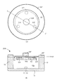
- A The top view which shows the 1st structural example of the blood flow rate sensor in 6th Embodiment, (B) AA 'sectional drawing of (A).
- A The top view which shows the 2nd structural example of the blood flow rate sensor in 6th Embodiment, (B) B-B 'sectional drawing of (A).
- A Schematic diagram showing an example of equal load distribution in the beam 65
- (A) Graph showing an example of the relationship between the distance from the center of the beam and the amount of bending of the beam in the equal load distribution
- (B) The relationship between the distance from the center of the beam and the inclination of the beam in the equal load distribution Graph showing an example
- (A) The top view which shows the structural example of the blood flow rate sensor in 7th Embodiment
- the blood flow measuring device 100 includes a blood flow sensor 200 and an electronic device 300.
- the electronic device 300 includes, for example, a mobile terminal device, a smartphone, a mobile phone, a tablet terminal, and other electronic devices.
- the blood flow sensor 200 is brought into contact with a measurement target part (for example, a human finger FG), emits light from the light source to the measurement target part, and receives light scattered at the measurement target part.
- the electronic device 300 acquires information on the amount of light received by the blood flow sensor 200 and measures the flow rate of the liquid (for example, blood) flowing through the measurement target site based on the information on the amount of received light.
- the blood flow sensor 200 and the electronic device 300 are configured separately.
- the blood flow sensor 200 and the electronic device 300 are connected wirelessly or by wire, and send information on the amount of received light measured by the blood flow sensor 200 to the electronic device 300.
- a blood flow sensor 200 and an electronic device 300 are connected by a micro USB (Universal Serial Bus) 250.
- the finger FG is in contact with the protrusion 60 provided in the blood flow sensor 200 in order to measure the blood flow.
- FIG. 2A and 2B are perspective views showing a second configuration example of the blood flow measuring device 100.
- the blood flow measuring device 100 includes a blood flow sensor 200 and an electronic device 300.
- the blood flow sensor 200 is built in the electronic device 300.
- the blood flow sensor 200 and the electronic device 300 may be integrally configured.
- the finger FG is in contact with the protrusion 60 provided on the blood flow sensor 200 in order to measure the blood flow.
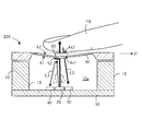
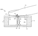
- FIG. 3 is a cross-sectional view showing a configuration example of the blood flow sensor 200 in the first embodiment.
- the blood flow sensor 200 includes a base 10, a VCSEL 20, a first photodiode 30, a second photodiode 40, an acrylic plate 50, and a protrusion 60.
- the base 10 is formed including silicon or ceramic, and accommodates each member of the blood flow sensor 200 (for example, the VCSEL 20, the first photodiode 30, and the second photodiode 40).
- the protrusion 60 is not accommodated inside the base 10.
- the base 10 is covered with an acrylic plate 50 at the top of the base 10.
- the upper end portion of the base 10 fixes both end portions of the acrylic plate 50.
- an accommodation space 10 a is formed inside the base 10.
- VCSEL Vertical Cavity Surface Emitting Laser 20 emits light. At least a part of the emitted light L1 emitted from the VCSEL 20 is directed to the finger FG via the acrylic plate 50 and the protrusion 60.
- the wavelength of the emitted light L1 is, for example, the wavelength of near-infrared light, for example, a wavelength of 850 nm to 1300 nm.
- the emitted light L1 is reflected or scattered (hereinafter also simply referred to as “scattering”) by the finger FG, and becomes the scattered light L2.
- the VCSEL 20 is an example of a light source.
- the mirror 52 is attached to the first surface A1 of the acrylic plate 50 facing the VCSEL 20.
- the emitted light L1 propagates in a substantially hemispherical shape while being repeatedly scattered or reflected by blood cells or tissues in capillaries in a measurement target site (for example, finger FG) in a user's biological tissue.
- Scattered light L2 obtained by reflecting or scattering the emitted light L1 by the finger FG is received by the first photodiode 30.
- the first photodiode 30 is a photodiode for a blood flow sensor (for blood flow measurement).
- the first photodiode 30 receives the scattered light L2 from the finger FG.
- the first photodiode 30 photoelectrically converts the scattered light L2 to generate a light detection signal corresponding to the intensity of the scattered light L2.
- the light detection signal may be amplified by an amplifier (not shown).
- the first photodiode 30 is an example of a light receiving element.
- the second photodiode 40 is a displacement detection photodiode.
- the second photodiode 40 receives the reflected light L3.
- the second photodiode 40 photoelectrically converts the reflected light L3 to generate a light detection signal corresponding to the intensity of the reflected light L3.
- the light detection signal may be amplified by an amplifier (not shown).
- the second photodiode 40 is an example of a pressure sensor.
- the deflection amount and inclination of the acrylic plate 50 are derived.
- the amount of bending of the acrylic plate 50 corresponds to the amount of bending y described later.
- the inclination of the acrylic plate 50 corresponds to a change rate (dy / dx) and an inclination ⁇ described later.
- the acrylic plate 50 has translucency with respect to the wavelengths of the outgoing light L1 and the scattered light L2. That is, the acrylic plate 50 is disposed between the VCSEL 20 and the finger FG, between the first photodiode 30 and the finger FG, and allows the emitted light L1 and the scattered light L2 to pass therethrough. In FIG. 3, the acrylic plate 50 has both ends of the acrylic plate 50 fixed to the upper end of the base 10. Therefore, the acrylic plate 50 becomes both rod beams (fixed beams at both ends).
- the acrylic plate 50 is an example of a translucent member.
- the protrusion 60 is disposed on the second surface A2 facing the finger FG of the acrylic plate 50.
- the protrusion 60 is disposed at the center of the acrylic plate 50, for example.
- the protrusion 60 has translucency with respect to the wavelengths of the outgoing light L1 and the scattered light L2. That is, the protrusion 60 is disposed between the VCSEL 20 and the finger FG, and between the first photodiode 30 and the finger FG, and allows the emitted light L1 and the scattered light L2 to pass therethrough.
- the protrusion 60 is made of acrylic, for example.
- the material is the same as that of the acrylic plate 50, the refractive index difference at the boundary between the acrylic plate 50 and the protrusion 60 is reduced, and the light transmittance is increased.
- the protrusion 60 may be formed of a translucent member other than acrylic.
- the first surface Ax1 of the protrusion 60 that contacts the acrylic plate 50 is smaller than the second surface A2 of the acrylic plate 50 (the area is small).
- the finger FG can come into contact with the entire surface of the second surface Ax2 that contacts the finger FG of the protrusion 60. That is, the second surface Ax2 of the protrusion 60 is smaller than the finger FG that contacts the protrusion 60. Therefore, when the protrusion 60 is pressed by the finger FG, the contact of the finger FG is received over the entire second surface Ax2 of the protrusion 60, and the contact pressure per unit area of the protrusion 60 is likely to be constant.
- the protrusion 60 is an example of a contact member.
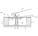
- FIG. 4 is a cross-sectional view showing a second configuration example of the blood flow sensor 200.
- the blood flow sensor 200 includes a base 10, a VCSEL 20, a first photodiode 30, a strain gauge 42, an acrylic plate 50, and a protrusion 60. That is, in FIG. 4, compared to FIG. 3, the blood flow measuring device 100 does not include the second photodiode 40 and the mirror 52 but includes the strain gauge 42.
- the strain gauge 42 is attached to, for example, the acrylic plate 50 and attached to the first surface A1.
- a plurality (for example, two) of strain gauges 42 are provided.
- the strain gauge 42 includes, for example, a metal foil arranged in a zigzag shape on an insulator, and the electric resistance changes due to deformation. As will be described later, based on the measurement value (change in electrical resistance) by the strain gauge 42, the deflection amount and inclination of the acrylic plate 50, the contact pressure with respect to the protrusion 60, and the load distribution are derived.
- load loading methods for example, the following first to third load loading methods are conceivable.
- the first load application method is a method of applying a load by moving the finger FG to contact the protrusion 60 as shown in FIGS.
- the second load application method is a method in which the finger FG is fixed, the blood flow sensor 200 including the protrusion 60 is moved, the finger FG and the protrusion 60 are brought into contact, and a load is applied.
- FIG. 5 is a cross-sectional view showing a configuration example of a blood flow measurement system 1000 that applies a load by the second load application method.
- a load is applied using the guide rail 70 and the weight 74.
- the same components as those in FIGS. 3 and 4 are denoted by the same reference numerals, and the description thereof is omitted or simplified.
- the blood flow measurement system 1000 includes a blood flow sensor 200 including a protrusion 60, an electronic device 300 (not shown), a guide rail 70, a base 72, and a weight 74.
- the configuration of the blood flow sensor 200 may be the same as in FIG. 3 or FIG.
- the blood flow sensor 200 is installed upside down with respect to the first load application method.
- the protrusion 60 is disposed at the end portion facing downward in the vertical direction.
- the guide rail 70 is formed in, for example, an L shape, and the base 72 is connected to a predetermined connection range.
- the base 72 is slidable in the vertical direction along the vertical direction with respect to the guide rail 70.
- a weight 74 is placed on the upper surface of the base 72. An arbitrary load is applied vertically downward by the weight 74.
- a blood flow sensor 200 is fixed to the lower surface of the base 72.
- the finger FG is fixedly positioned below the blood flow sensor 200 so as to face the protrusion 60. That is, in the first load loading method, the finger FG is moved to bring the finger FG into contact with the protrusion 60. However, in the second load loading method, the finger FG is fixed and the base 72 is moved to move the finger FG. The protrusion 60 is brought into contact with the surface.
- the blood flow measuring system 1000 can appropriately apply the load to the protrusion 60 with the finger FG.
- the finger FG is fixed, it is possible to suppress an error in a load load accompanying the movement of the finger FG, to suppress variations in measurement values, and to improve the reproducibility of measurement results.
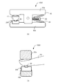
- the third load application method is a method in which the finger FG is sandwiched between clips, the finger FG and the protrusion 60 are brought into contact with each other, and a load is applied.
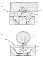
- FIGS. 6A and 6B are cross-sectional views showing a configuration example of a blood flow measurement system 1000 that applies a load by the third load application method.
- the blood flow measurement system 1000 includes a blood flow sensor 200 including a protrusion 60, an electronic device 300 (not shown), a clip 82, a leaf spring 84, and a screw 86.
- the configuration of the blood flow sensor 200 may be the same as in FIG. 3 or FIG.
- the clip 82 includes a clip upper part 82a and a clip lower part 82b.
- a blood flow sensor 200 is attached to the clip lower part 82b at a predetermined position, and the protrusion 60 projects into a space (measurement space) sandwiched between the clip upper part 82a and the clip lower part 82b.
- the finger FG is inserted into this measurement space.
- the clip 80 holds the finger FG with the finger FG in contact with the protrusion 60.
- the leaf spring 84 urges the clip upper part 82a and the clip lower part 82b in directions away from each other.
- the biasing force of the leaf spring 84 is adjusted by the screwed state of the screw 86.
- the screw 86 engages the leaf spring 84 with the clip 82.
- the distance between the clip upper part 82a and the clip lower part 82b is changed by the leaf spring 84 by turning the screw 86, and the load applied to the protrusion 60 by the finger FG is changed.
- the clip upper part 82a and the clip lower part 82b are used, but the clip upper part 82a does not necessarily have to be on the upper side in the vertical direction, and the clip lower part 82b does not have to be on the lower side in the vertical direction.
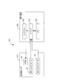
- FIG. 7 is a block diagram showing an example of the electrical configuration of the blood flow measuring device 100.
- the second photodiode 40 is exemplified.
- the blood flow sensor 200 includes a VCSEL 20, a first photodiode 30, and a second photodiode 40.
- the electronic device 300 includes a processor 310, a memory 320, and a display 330.
- the VCSEL 20 emits outgoing light L1 by driving a laser driving circuit (not shown).
- the driving of the laser drive circuit may be performed in accordance with a control signal from the electronic device 300.
- the VCSEL 20 may send information related to the emitted light L1 (information on the amount of emitted light and the wavelength of the emitted light L1) to the electronic device 300.
- the first photodiode 30 sends a light detection signal including information (detection information) on the amount of received light and the intensity of the scattered light L2 to the electronic device 300.
- the second photodiode 40 sends a light detection signal including information (detection information) of the amount of received light and the intensity of the reflected light L3 to the electronic device 300.
- the blood flow sensor 200 includes the strain gauge 42
- a detection value (detection information) by the strain gauge 42 is sent to the electronic device 300.
- the processor 310 acquires (for example, receives) detection information from the blood flow sensor 200.
- the processor 310 may send a control signal to the blood flow sensor 200.
- the processor 310 includes, for example, an MPU (Micro Processing Unit), a CPU (Central Processing Unit), or a DSP (Digital Signal Processor).
- MPU Micro Processing Unit
- CPU Central Processing Unit
- DSP Digital Signal Processor
- the processor 310 performs various processes by executing a program held in the memory 320.
- the various processes include, for example, calculation related to blood flow measurement and warning information display. Details of various processes performed by the processor 310 will be described later.
- the memory 320 includes, for example, a primary storage device such as a ROM (Read Only Memory) and a RAM (Random Access Memory).
- the memory 320 may include a secondary storage device such as an SD card.
- the memory 320 holds various data and various programs.
- the memory 320 may be built in the processor 310.
- the display 330 includes, for example, an LCD (Liquid Crystal Display) and displays various data.
- the display 330 displays an image, a character, a symbol, a figure, or data obtained by combining any two or more of these.
- the display 330 displays warning information related to blood flow measurement.
- the blood flow measuring device 100 can guide the user so that, for example, the contact of the finger FG with the protrusion 60 has an equal load distribution, that is, the contact pressure per unit area is constant.
- the processor 310 calculates the amount of deflection and the inclination of the acrylic plate 50 based on the detection information from the second photodiode 40 (for example, the intensity change of the reflected light L3).
- the inclination of the acrylic plate 50 is indicated by, for example, an inclination with respect to a reference direction (here, the extending direction d1 when the acrylic plate 50 is not loaded, and the horizontal direction in FIGS. 3 and 4). Further, the processor 310 calculates the contact pressure of the finger FG on the protrusion 60 based on the deflection amount and inclination of the acrylic plate 50 and estimates the load distribution on the protrusion 60.
- the processor 310 calculates the deflection amount and the inclination of the acrylic plate 50 based on the detection information of the strain gauge 42. Further, the processor 310 calculates the contact pressure of the finger FG on the protrusion 60 based on the deflection amount and inclination of the acrylic plate 50 and estimates the load distribution on the protrusion 60.
- the processor 310 calculates the blood flow volume based on the detection information by the first photodiode 30 using the Doppler shift.
- the calculation of the blood flow may be started at an arbitrary timing.
- the processor 310 calculates (measures) the contact pressure to the protrusion 60 (that is, the contact pressure to the acrylic plate 50), and detects that the contact pressure to the protrusion 60 is a predetermined contact pressure (for example, 80 mmHg).
- the calculation of the blood flow may be started.
- the calculation of the blood flow volume may be performed while sequentially changing the contact pressure to the protrusion 60.
- the processor 310 has a function as a flow rate measurement unit.
- a frequency shift occurs due to the Doppler effect proportional to the moving speed of the blood cells.
- a difference (shift) in frequency between the scattered light L2 from the stationary tissue and the scattered light L2 from the moving blood cell is distributed in a band of about several hundred Hz to several tens kHz.
- the processor 310 can calculate the blood flow by multiplying the power spectrum of the beat signal described above by frequency and integrating the beat signal.
- the processor 310 performs frequency analysis of the interference component of the scattered light L2 (for example, FFT (Fast Fourier Transform) calculation) on the detection information from the first photodiode 30.
- the processor 310 derives (calculates) a spectrum sequence of the beat signal by frequency analysis, and derives (calculates) the blood flow volume of the finger FG by multiplying and integrating each spectrum sequence by a corresponding frequency. Further, the processor 310 may display information related to the blood flow as the measurement result via the display 330.
- FFT Fast Fourier Transform
- FIG. 8 is a schematic diagram illustrating an example of changes in blood flow due to contact pressure on the finger FG.
- FIG. 8 shows temporal changes in blood flow (units: a, u) at each pressure of 0, 20, 40, 60, 80, 100 (unit: mmHg).
- the blood pressure waveform amplitude (pulse wave amplitude) is relatively small at 0, 20, 40, 60 (mmHg) contact pressure, and the pulse wave amplitude at 80, 100 (mmHg) contact pressure. Is relatively large, and it can be understood that the pulse wave amplitude becomes large particularly when the contact pressure is 80 (mmHg).
- the pulse wave amplitude is also related to blood pressure measurement.
- the blood flow measurement can be stably performed and the reproducibility is higher when the amplitude of the blood flow waveform is larger. Therefore, it is preferable that the blood flow rate is measured with the finger FG at a constant contact pressure (for example, 80 (mmHg)) with respect to the blood flow sensor 200.
- a constant contact pressure for example, 80 (mmHg)
- the blood flow measuring device 100 may measure the blood flow when the contact pressure to the protrusion 60 is a predetermined contact pressure (for example, 80 (mmHg)). That is, when the contact pressure on the protrusion 60 is a predetermined contact pressure (for example, 80 (mmHg)), emission of the emitted light L1 and reception of the scattered light L2 for blood flow measurement may be performed.
- This contact pressure may be derived, for example, based on the amount of deflection detected by the second photodiode 40 or the strain gauge 42, or may be detected by providing another pressure sensor.
- FIG. 9A is a schematic diagram showing an example of a contact pressure distribution of a finger FG (user's fingertip).
- FIG. 9B is a schematic diagram illustrating an example of the Mises stress distribution of the finger FG (user's fingertip).
- the blood flow measuring device 100 includes the protrusion 60 so that the entire surface can be easily pressed by the finger FG as the measurement target region. Thereby, it can suppress that the measured value of the blood flow rate good for the contact position of the finger FG changes greatly.
- FIGS. 10A and 10B are schematic diagrams showing an example of equal load distribution in both rod beams 65 (also simply referred to as “beams”).
- each parameter indicates the following.
- P Total load “ ⁇ ” on the both beams 65
- l Length in the longitudinal direction of both beams 65
- b Both Length “h” in the depth direction (short direction) of the glutinous beam 65: Height “E” of the glutinous beam 65: Young's modulus “I” of the glutinous beam 65: Sectional second moment of the glutinous beam 65
- the longitudinal position (the distance from the base point (the left end of the both ends 65 in FIG. 10A)) of the both ends 65 is represented by a variable x.
- the position in the height direction of both the rod beams 65 (the distance from the base point (the upper end of both rod beams 65 in FIG. 10A)) is represented by a variable y.
- the variable y corresponds to the amount of bending of the both ends 65.
- the amount of deflection (y) of both rod beams 65 is expressed by, for example, (Equation 1).
- the rate of change (dy / dx) of the deflection amount (y) at each position in the longitudinal direction of both rod beams 65 is expressed by, for example, (Expression 3). This rate of change corresponds to a change in the amount of deflection with respect to a minute change in the position in the longitudinal direction of both rod beams 65.
- FIG. 11 is a schematic diagram showing an example of the wedge load distribution in the both timber beams 65.
- the load increases stepwise along the longitudinal direction of the both ends 65.
- the amount of deflection (y) of both rod beams 65 is expressed by, for example, (Formula 5).
- the contact area can be easily made constant, and the contact portion length ⁇ can be easily made constant, so that the bending amount of the acrylic plate 50 can be easily made constant.
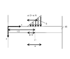
- FIG. 12A is a schematic diagram illustrating an example of parameters used in the first simulation.
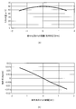
- FIG. 12B is a graph illustrating an example of the relationship between the deflection amount y of the beam center portion c1 and the contact length ⁇ .
- FIG. 12C is a graph illustrating an example of the influence of the change (inclination) of the contact length with respect to the both beams 65.
- FIG. 12C shows that the value of dy / d ⁇ approaches 0 when the contact length ⁇ is short. That is, it can be seen that the change in the deflection amount y with respect to the minute change in the contact length ⁇ approaches 0, and the influence on the deflection amount y due to the change in the contact length ⁇ is small.
- the contact length ⁇ is about 20 mm
- the value of dy / d ⁇ is minimized, and the value of dy / d ⁇ increases as the contact length ⁇ becomes longer than 20 mm. This is because the length l of both rod beams 65 here is 29.5 mm, and as the contact length ⁇ approaches the length l, it becomes difficult to bend.
- the finger contacts the blood flow sensor 200 with a contact length ⁇ as small as possible, that is, with a contact area as small as possible.
- the blood flow sensor 200 includes the protrusions 60 so that the contact area with the acrylic plate 50 as the both ends 65 is as small as possible.
- the blood flow measuring device 100 measures the blood flow when the finger FG presses the acrylic plate 50 through the protrusion 60. Thereby, the user can make the contact area with respect to the acrylic plate 50 constant through the protrusion 60 uniformly.
- the contact area with the acrylic plate 50 changes.
- the deflection amount y of the acrylic plate 50 The impact on change can be reduced. Therefore, the measurement result of blood flow measurement is stabilized.
- FIG. 13 is a graph showing the relationship between the deflection amount y of the beam center portion c1 and the contact length ⁇ when both the rod beams 65 are made of acrylic.
- FIG. 13 shows a graph G1 showing the theoretical value of the deflection amount y with respect to the contact length ⁇ when the Young's modulus E of the both ends 65 is 2.2. This theoretical value is the maximum value.
- a graph G2 showing a theoretical value of the deflection amount y with respect to the contact length ⁇ when the Young's modulus E of both the beam beams 65 is 3.14 is shown. This theoretical value is the minimum value.
- FIG. 13 shows the average value of the measurement results of the deflection amount y with respect to the contact length ⁇ when the load distribution is an equal load distribution.
- the average value of 12 measurements is shown. From FIG. 13, it can be understood that the actual measurement result is roughly included between the maximum value and the minimum value of the theoretical value of the deflection amount y with respect to the contact length ⁇ .
- the number of measurements 12 is an example, and other numbers may be used.
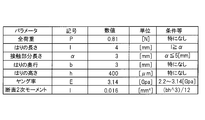
- FIG. 14 is a schematic diagram illustrating an example of parameters used in the second simulation.
- the deflection amount y and the inclination ⁇ of the both beam 65 for each load distribution are considered.
- “bh ⁇ 3” appears in the column of the condition of the sectional second moment, etc., and this indicates “bh 3 ”. That is, in each embodiment, “A ⁇ B” indicates “A B” (A raised to the B power).
- FIGS. 15A to 15C are schematic diagrams showing an example of the load distribution.
- FIG. 15A shows an equal load distribution in which the total load is L and the load per unit area is constant over the entire beam 65.
- FIG. 15B shows a first wedge load distribution in which the total load is also L.
- FIG. 15C shows a second wedge load distribution in which the total load is also L.
- the minimum load position is the left end (the end in the negative direction as viewed from the beam center portion c1) of the contact portion of the both beam 65 with the measurement target portion in the drawing. ).
- the maximum load position is the right end (the end in the positive direction when viewed from the beam center portion c1) of the contact portion of the both ends beam 65 with the measurement target site in the drawing.
- the load increases by the same amount from the left end toward the right end, and the load at the right end becomes twice the load at the left end.
- the minimum load position is the left end of the contact portion of the both beam 65 with the measurement target site in the drawing.
- the maximum load position is the right end of the contact portion of both rod beams 65 in the drawing with the portion to be measured. The load increases by the same amount from the left end toward the right end, and the load at the left end is zero.
- FIG. 16A is a graph showing an example of the relationship between the distance from the beam center portion c1 and the deflection amount y of the beam ends 65 in the equal load distribution.
- FIG. 16B is a graph showing an example of the relationship between the distance from the beam center portion c1 and the inclination ⁇ of the beam ends 65 in the equal load distribution.
- the deflection amount y at the beam center portion c1 is maximized.
- the beam ends 65 are parallel to (for example, horizontal) the extending direction of the beam ends 65 when there is no load.
- the slope ⁇ is 0.
- the value of the inclination ⁇ corresponds to the value of the rate of change (dy / dx) of the amount of deflection (y) at each position in the longitudinal direction (the left-right direction in FIGS. 10 and 11) of the both beams 65 described above. .
- FIG. 17A is a graph showing an example of the relationship between the distance from the beam center portion c1 in the first wedge load distribution and the deflection amount y of the beam ends 65.
- FIG. 17B is a graph showing an example of the relationship between the distance from the beam center portion c1 in the first wedge load distribution and the inclination ⁇ of the beam ends 65.
- the load is not uniform at the contact portion of the both ends beam 65 with the measurement target portion, and the load gradually increases in the positive direction from the beam center portion c1. Therefore, as shown in FIG. 17A, the deflection amount y at the position slightly shifted in the positive direction from the beam center portion c1 (here, the position +0.05 from the beam center portion c1) is maximized.
- the position where the beam is parallel to the extending direction and the inclination ⁇ is 0 is slightly shifted from the beam center portion c1 in the positive direction.
- the inclination ⁇ is about 0.14.
- FIG. 18 (A) is a graph showing an example of the relationship between the distance from the beam center portion c1 and the deflection amount y of the beam ends 65 in the second wedge load distribution.
- FIG. 18B is a graph showing an example of the relationship between the distance from the beam center c1 in the second wedge load distribution and the inclination ⁇ of the beam ends.
- the load is non-uniform at the contact portion between the both ends of the beam 65 and the measurement target portion, and the load is more sudden than the first wedge load distribution in the positive direction from the beam center portion c1. Is getting bigger. Therefore, as shown in FIG. 18A, the deflection amount y at the position shifted in the positive direction from the beam center portion c1 (here, the position +0.1 from the beam center portion c1) is maximized.
- the position where the beam is parallel to the extending direction and the inclination ⁇ is 0 is shifted from the beam center portion c1 in the positive direction.
- the deviation in the positive direction is larger than in the case of the first wedge load distribution.
- the inclination ⁇ is about 0.40, which is larger than that in the case of the first wedge load distribution.
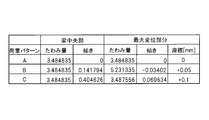
- FIG. 19 is a schematic diagram showing the deflection amount y and the inclination ⁇ of the rod-like beam 65 at the beam center portion c1 and the maximum displacement portion in each load pattern (each load distribution).
- A indicates a load pattern A, which indicates an equal load distribution.
- B indicates the load pattern B, which indicates the first wedge load distribution.
- C indicates the load pattern C, which indicates the second wedge load distribution.
- the deflection amount y at the beam center portion c1 becomes smaller and the inclination ⁇ becomes smaller. It can be understood that it tends to be close to 0 and become horizontal.
- the received light amounts of the scattered light L2 and reflected light L3 from the first photodiode 30 and the second photodiode 40 change, and the received light amount varies. It can happen. Therefore, the measurement result of the blood flow based on the scattered light L2 varies, and the reproducibility may be reduced.
- the processor 310 determines the inclination ⁇ of the protrusion 60 or the acrylic plate 50 with respect to the extending direction d1 of the protrusion 60 or the acrylic plate 50 at the beam center c1 by using the second photodiode 40 or the strain gauge. Derived based on the detection information by 42.
- the blood flow measuring device 100 can determine whether the load is an equal load distribution, a wedge load distribution, a degree of bias of the load distribution, or the like based on the value of the inclination ⁇ .
- the display 330 displays warning information when the inclination ⁇ is larger than the threshold th under the control of the processor 310.
- the threshold th is, for example, the value 0.
- the warning information may be a message such as “Please press the middle”.
- the user can acquire information related to a preferable method of pressing the protrusion 60, and can consciously touch the center of the protrusion 60 with the finger FG. For example, even if the user intends to push the projection 60 so as to obtain an equal load distribution, the user can understand that the wedge load distribution is obtained. Accordingly, the amount of scattered light L2 received by the first photodiode 30 is stabilized, the measurement accuracy of blood flow measurement is improved, and the reproducibility of blood flow measurement can be improved.
- the acrylic plate 50 is in contact with the measurement target part (for example, the finger FG) via the protrusion 60, and therefore the measurement target part (for example, the finger FG) of the both ends 65 is used as the acrylic plate 50.
- the contact portion is a contact portion with the protrusion 60.
- the reproducibility of the blood flow measurement result is considered using the rat tail, but the reproducibility using the human finger FG is considered to be the same.
- the reproducibility of the measurement result of blood flow when a human finger FG is used will be described in a later-described seventh embodiment.
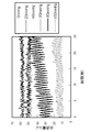
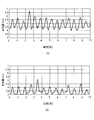
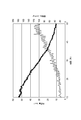
- FIG. 20A is a graph showing temporal changes in blood flow in the tail of the rat measured by the blood flow measuring device 100 in which the protrusion 60 is not provided.
- the horizontal axis represents time (seconds), and the vertical axis represents blood flow (au).
- FIG. 20 (A) shows the measurement results when 1% anesthesia was administered to the rat's tail and a 43 g load was applied.
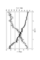
- FIG. 20 (B) is a graph showing temporal changes in blood flow in the tail of the rat measured by the blood flow measuring device 100 provided with the protrusions 60.
- FIG. The horizontal axis represents time (seconds), and the vertical axis represents blood flow (au).
- FIG. 20 (B) shows the measurement results when anesthesia was administered at 1% to the rat's tail and a 43 g load was applied.
- a projection 60 having a contact surface that contacts the rat's tail, that is, the length of each side of the second surface Ax2 is 5 mm ⁇ 4 mm and the height is 2 mm is used.
- FIG. 20A it can be understood that there are variations in the blood flow measurement results.
- the variation in the measurement results is based on the contact position and pressure at which the rat's tail contacts the blood flow sensor 200 (for example, the acrylic plate 50) when the blood flow of the rat's tail is measured using the blood flow measuring device 100. It is thought that this occurred because the contact area, etc. were not constant.
- the protrusion 60 is not provided, it is considered that there is no reference for the rat's tail to contact the blood flow sensor 200 and it is difficult to make a stable contact.
- FIG. 20B it can be understood that the measurement result of the blood flow rate has little variation, that is, it is measured 10 times with good reproducibility.
- the contact position and contact pressure at which the rat's tail contacts the blood flow sensor 200 for example, the protrusion 60. It is considered that the contact area, etc. were constant. It is considered that the protrusion 60 serves as a reference for the rat's tail to contact the blood flow sensor 200, contributes to the stable blood flow sensor 200, and can measure blood flow with good reproducibility.
- the height of the protrusion 60 is 2 mm, which is an example, and other values may be used. It is desirable that the height of the protrusion 60 is such a height that the finger FG does not contact the acrylic plate 50 on which the protrusion 60 is disposed when the finger FG contacts the protrusion 60 during blood flow measurement.
- the length of each side of the protrusion 60 on the second surface Ax2 is 5 mm ⁇ 4 mm, and it may be another value.
- the contact area that contacts the measurement target portion becomes small as described above, and thus the acrylic plate depending on the contact condition of the measurement target portion A change in the deflection amount y of 50 can be suppressed. Therefore, the stability of the measurement result of the blood flow measurement can be increased, and the reproducibility can be improved.
- a protrusion 60 having a length of 5 mm ⁇ 4 mm and a height of 2 mm at the contact surface in contact with the tail of the rat is used.
- FIG. 21 (A) is a graph showing temporal changes in the blood flow in the tail of healthy rats (rats before dehydration).
- the projection 60 is provided in the blood flow sensor 200, the body temperature of the rat is 28.6 ° C., anesthesia is administered at 1%, and a load of 43 g is applied. Show.
- FIG. 21 (B) is a graph showing the time change of blood flow in the tail of a dehydrated rat.
- the projection 60 is provided in the blood flow sensor 200
- the body temperature of the rat is 28.6 ° C.
- anesthesia is administered at 1%
- a load of 43 g is applied. Show.
- the blood flow in the tail of the rat is generally stable at a value of 4.0 to 6.5.
- the blood flow in the tail of the rat is generally stable at a value of 3.0 to 5.0.
- the average blood flow rate is 4.98 (the unit is omitted. The same applies hereinafter) and the average blood flow amplitude is 0.924, whereas FIG. In the dehydrated rat corresponding to (B), the average blood flow was 3.54 and the average blood flow amplitude was 0.642.
- both the blood flow volume and the blood flow amplitude decrease as the dehydrated state from the healthy state in the same rat (in other words, the individual) and the same measurement condition.
- the reason for the decrease in blood flow is that the amount of circulating blood decreases or the proportion of cellular components (eg, hematocrit) increases due to, for example, a decrease in water in the body as the state transitions from a healthy state to a dehydrated state. This is probably because of this.
- the reason for the decrease in blood flow amplitude is that as the transition from a healthy state to dehydration occurs, the pulsation associated with the decrease in the amount of circulating blood decreases and the extensibility of blood vessels due to dehydration decreases. It is believed that there is.
- the blood flow can be measured with high reproducibility, and as described above, the reliability of the measured blood flow is high. Therefore, the presence or absence of a dehydration state can be estimated with high accuracy according to the amount of blood flow. Further, when the blood flow rate is increased, for example, the hematocrit indicating the ratio of the volume of blood cells in the blood becomes higher than the normal range value (in other words, dehydrated), or the blood viscosity is healthy, for example. The dehydrated state is higher than the state. For this reason, it is considered that the presence or absence of dehydration symptoms becomes easy due to the large amount of blood flow.
- the blood flow sensor 200 (for example, the processor 310 as an example of the dehydration state identification unit) of the present embodiment has a blood flow in the tail of the rat as shown in FIG.
- the predetermined value is a threshold for the blood flow sensor 200 to identify that the measurement target site (for example, the rat tail or the human finger FG) is dehydrated, and is defined in the operation of the processor 310, for example. ing.
- the blood flow sensor 200 (for example, the processor 310 as an example of the dehydration state identifying unit) of the present embodiment, when the blood flow is lower than the predetermined value described above (for example, as shown in FIG. 21B), It is possible to identify dehydration symptoms when the blood flow in the tail is stable at a value of 3.0 to 5.0.
- the blood flow sensor 200 of the present embodiment can not only simply measure the blood flow of blood flowing through a measurement target site (for example, a human finger FG or a rat tail), but can also accurately detect a dehydrated rat. It can be said that it can be identified.
- the blood flow sensor 200 by reducing the intravascular pressure of the subject by raising the hand, It is known to detect whether the subject has dehydration.
- the blood flow sensor 200 according to the present embodiment relatively reduces the intravascular pressure of the subject by applying a predetermined contact pressure to the protrusion 60 without causing the subject to raise his hand. The presence or absence of dehydration can be detected easily and with high accuracy, and the same applies to the configuration of the blood flow sensor in each of the following embodiments.
- the blood flow sensor 200 of this embodiment gives a predetermined contact pressure with respect to the protrusion 60 instead of raising a subject's hand, for example, not only dehydration, but the presence or absence of scleroderma or drinking. It is also possible to detect the same, and the same applies to the configuration of the blood flow sensor in each of the following embodiments.
- the blood flow sensor 200 of the present embodiment has a predetermined contact pressure applied to the protrusion 60 as in the present embodiment, as compared to the conventional method in which the subject raises his hand and measures the blood flow.
- the blood flow in the measurement target part for example, finger FG
- the measurement target part for example, finger FG
- the subject has symptoms such as dehydration, scleroderma, alcohol drinking, that is, the biological information (vital information) of the subject. It can be grasped simply and with high accuracy.
- the blood flow measuring device 100 of the first embodiment by providing the protrusion 60, the protrusion 60 serves as a standard of the contact location, and the contact area of the finger FG with respect to the blood flow measuring device 100 is easily constant. Can be. Therefore, the blood flow measuring device 100 can easily make the contact pressure per unit area constant, can suppress variations in measurement values of blood flow measurement, and can improve the reproducibility of blood flow measurement.
- warning information may be displayed on the display 330 when the load distribution on the protrusion 60 is not equal.
- the user can recognize what kind of load distribution is in contact with the protrusion 60, and can press down the protrusion 60 so as to obtain an equal load distribution.
- the blood flow rate measuring apparatus 100 can suppress the dispersion
- the blood flow measuring device 100 may measure blood pressure based on the blood flow measurement result.
- the processor 310 calculates the average blood pressure of the finger FG based on the pulse wave amplitude of the blood flow with a high degree of reproducibility and a small variation in the measurement values derived as described above. May be derived (calculated).
- the processor 310 derives (calculates) the maximum blood pressure based on the blood flow obtained by multiplying the pulse wave amplitude of the blood flow at the time when the average blood pressure is obtained by a predetermined first coefficient (for example, 0.5). May be.
- a predetermined first coefficient for example, 0.5
- the processor 310 derives (calculates) the minimum blood pressure based on the blood flow obtained by multiplying the pulse wave amplitude of the blood flow at the time when the average blood pressure is obtained by a predetermined second coefficient (for example, 0.4). May be.
- a predetermined second coefficient for example, 0.4
- a known method for example, Patent Document 2 may be used.
- the blood flow measuring device 100 can derive the average blood pressure of the finger FG based on the pulse wave amplitude of the blood flow with high reproducibility. Therefore, the blood flow measuring device 100 can also suppress variations in measured values of blood pressure measurement regarding blood pressure, and can improve the reproducibility of blood pressure measurement.
- FIG. 22 is a cross-sectional view showing a blood flow sensor according to a modification.
- the blood flow sensor 200a in FIG. 22 is the same as the blood flow sensor 200 in FIGS. 3 and 4, but includes an acrylic plate 50a instead of the acrylic plate 50. 22, the same components as those in FIG. 3 are denoted by the same reference numerals, and the description thereof is omitted or simplified.
- the thick part 54 is formed in the acrylic plate 50a in a predetermined range including the position of the acrylic plate 50a where the protrusion 60 is disposed.
- a thin portion 53 is formed in a range other than the thick portion 54 of the acrylic plate 50a.
- the thick part 54 and the thin part 53 may be formed of different materials. Therefore, the thick portion 54 includes a position facing the protrusion 60.
- the thin portion 53 includes a position that does not face the protrusion 60.
- the predetermined range (that is, a predetermined range including the position of the acrylic plate 50a where the protrusion 60 is disposed), a portion through which the emitted light L1 and the scattered light L2 pass is included.
- the predetermined range is intended to be a range in which when the finger FG comes into contact with the protrusion 60, a stress of a predetermined value or more is applied and the acrylic plate 50a is likely to be deformed.
- the predetermined range has such a thickness that the finger FG contacts the protrusion 60 and does not contact the thin portion 53 when the finger FG comes into pressure contact with the protrusion 60.
- the thickness of the thick part is less than 2 mm and the thickness of the thin part is 0.3 mm. And can be changed according to the size of the blood flow sensor 200. For example, when the measurement target site is a finger FG, the length of the thick portion 54 is about 4.5 mm in diameter.
- the thick wall portion 54 has high rigidity, even if a load is applied to the protrusion 60 by the finger FG, the thick wall portion 54 of the acrylic plate 50 is difficult to be bent and tilted.
- the thick portion 54 is formed in the acrylic plate 50a where the emitted light L1 and the scattered light L2 pass. Therefore, the blood flow measuring device 100 can suppress the influence of the load distribution such as the equal load distribution and the wedge load distribution on the inclination of the acrylic plate 50a by making the acrylic plate 50a difficult to bend. Therefore, the blood flow measuring device 100 can stabilize the amount of light received by the scattered light L2 from the first photodiode 30, improve the measurement accuracy of the blood flow measurement using the Doppler shift, and improve the reproducibility of the blood flow measurement.
- the second embodiment differs from the first embodiment in the blood flow sensor in the blood flow measuring device.
- the blood flow sensor includes the protrusion 60.
- the blood flow sensor does not include the protrusion 60.
- the blood flow sensor is a micromachine that is smaller in size than the first embodiment.
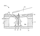
- FIG. 23 is a cross-sectional view showing a configuration example of a blood flow sensor 200A in the second embodiment.
- the same components as those of the first embodiment are denoted by the same reference numerals, and description thereof is omitted or simplified.
- the blood flow sensor 200 ⁇ / b> A includes a base 10, a VCSEL 20, a first photodiode 30, a second photodiode 40, and an acrylic plate 50.
- the blood flow sensor 200A does not include a protrusion on the second surface A2 facing the finger FG of the acrylic plate 50.
- the acrylic plate 50 is in contact with the finger FG during blood flow measurement, but the entire second surface A2 can be in contact with the finger FG. That is, the contact area of the contact surface of the finger FG that contacts the acrylic plate 50 is equal to the area of the second surface A2 of the acrylic plate 50, and the contact area is constant. Thereby, it becomes easy to press with respect to 2nd surface A2 of the acrylic plate 50 by equal load distribution, and the precision of a blood flow rate measurement improves.
- the acrylic plate 50 is an example of a contact member.
- a strain gauge 42 may be provided instead of the second photodiode 40.
- the blood flow measuring device including the blood flow sensor 200A of the present embodiment, even if the protrusion 60 is omitted, the finger FG can contact the entire surface of the acrylic plate 50, and the contact area can be made constant. . Therefore, the blood flow measuring device can be easily contacted with an equal load distribution, the accuracy of blood flow measurement can be improved, and the reproducibility of blood flow measurement is improved.
- the blood flow sensor in the blood flow measuring device is different from the first and second embodiments.
- the blood flow sensor does not have a protrusion.
- the strain gauge is embedded in the acrylic plate.
- FIG. 24 is a cross-sectional view showing a configuration example of a blood flow sensor 200B according to the third embodiment.
- the same components as those in the first or second embodiment are denoted by the same reference numerals, and description thereof is omitted or simplified.
- the blood flow sensor 200B includes a base 10, a VCSEL 20, a first photodiode 30, a strain gauge 42B, and an acrylic plate 50B. However, the blood flow sensor 200B has no protrusion on the second surface A2 facing the finger FG of the acrylic plate 50B.
- strain gauge 42B is embedded in the acrylic plate 50B.
- the facing surface A3 facing the finger FG of the strain gauge 42B is located on the same plane as the second surface A2 of the acrylic plate 50.
- a small strain gauge 42B is embedded in the acrylic plate 50B, and the strain gauge 42B detects the deflection or inclination of the finger FG per unit area.
- the contact pressure is derived from the deflection and inclination.
- the strain gauge 42B comes into contact with the finger FG during blood flow measurement, but the entire opposing surface A3 can come into contact with the finger FG. That is, the contact area of the contact surface of the finger FG that contacts the acrylic plate 50 is equal to the area of the facing surface A3 of the strain gauge 42B, and the contact area is constant. Thereby, it becomes easy to press with respect to opposing surface A3 of the strain gauge 42B by equal load distribution, and the precision of a blood flow rate measurement improves.
- the inside of the strain gauge 42B contains a metal resistor as a micro beam.
- the micro beam is displaced by the contact pressure, and the deflection is detected, that is, the pressure is measured. That is, the contact area of the finger FG with the strain gauge 42B as a pressure sensor that determines the pressure is constant, and the size of the strain gauge 42B is smaller than the finger FG.
- the blood flow measuring device including the blood flow sensor 200B of the present embodiment, even when the protrusion 60 is omitted, even when it is difficult to contact the finger FG with the entire surface of the acrylic plate 50B, pressure measurement is possible.
- the contact area of the finger FG with respect to the strain gauge 42B can be made constant. Therefore, the blood flow measuring device can be easily contacted with an equal load distribution, the accuracy of blood flow measurement can be improved, and the reproducibility of blood flow measurement is improved.
- FIG. 25A is a side sectional view of a flow sensor 200C according to the fourth embodiment.
- FIG. 25B is a front sectional view of the flow sensor 200C.
- the same components as those in the first to third embodiments are denoted by the same reference numerals, and description thereof is omitted or simplified.
- the tube 90 is excellent in flexibility, for example.
- the tube 90 is an example of a tubular member.
- the flow sensor 200C includes a base 10, a laser diode (LD) 22, a first photodiode (PD) 30, a strain gauge 42C, a glass plate 50C, and a protrusion 60C.
- LD laser diode
- PD first photodiode
- strain gauge 42C strain gauge
- glass plate 50C glass plate 50C
- protrusion 60C protrusion
- the laser diode 22 emits outgoing light L1.
- the emitted light L1 is reflected by the mirror 12 disposed on the base 10, passes through the glass plate 50C, and travels toward the tube 90 as a measurement target site.
- the VCSEL 20 described above may be provided instead of the laser diode 22.
- the first photodiode 30 receives the scattered light L2 obtained by scattering or reflecting the emitted light L1 in the tube 90 through the protrusion 60C and the glass plate 50C.
- the emitted light L1 from the laser diode 22 is reflected by the mirror 12 of the base 10, passes through the glass plate 50C, and travels to the blood inside the tube 90.
- the glass plate 50 ⁇ / b> C has a convex curved surface 56 a, and the emitted light L ⁇ b> 1 of the laser diode 22 is condensed at a predetermined position inside the tube 90 by the convex curved surface 56 a.
- the scattered light L2 scattered or reflected at the predetermined position passes through the protrusion 60C and the glass plate 50C and is received by the first photodiode 30.
- the glass plate 50C has translucency with respect to the wavelengths of the outgoing light L1 and the scattered light L2. That is, the glass plate 50C is disposed between the laser diode 22 and the finger FG and between the first photodiode 30 and the finger FG, and allows the emitted light L1 and the scattered light L2 to pass therethrough. 25A and 25B, the glass plate 50C has both ends of the glass plate 50C fixed to the upper end of the base 10. Therefore, the glass plate 50 ⁇ / b> C becomes both rod-like beams (fixed beams at both ends).
- the glass plate 50C is an example of a translucent member.
- the above-mentioned acrylic plate 50 may be provided instead of the glass plate 50C.
- the protrusion 60C is disposed on the second surface C2 facing the tube 90 of the glass plate 50C.
- the protrusion 60C is disposed, for example, at the center of the glass plate 50C.
- the protrusion 60C has translucency with respect to the wavelengths of the emitted light L1 and the scattered light L2. That is, the protrusion 60C is disposed between the laser diode 22 and the tube 90, and between the first photodiode 30 and the tube 90, and allows the emitted light L1 and the scattered light L2 to pass therethrough.
- the protrusion 60C is made of, for example, glass.
- the material is the same as that of the glass plate 50C, the difference in refractive index at the boundary between the glass plate 50C and the protrusion 60C is reduced, and the light transmittance is increased.
- the protrusion 60C may be formed of a light-transmitting member other than acrylic.
- the first surface Cx1 that contacts the glass plate 50C of the protrusion 60C is smaller than the second surface C2 of the glass plate 50C (the area is small).
- the tube 90 can contact the whole surface of the 2nd surface Cx2 which contacts the tube 90 of protrusion 60C. That is, the second surface Cx2 of the protrusion 60 is smaller than the tube 90 that contacts the protrusion 60C. Therefore, when the projection 60C is pressed by the tube 90, the tube 90 is received over the entire second surface Cx2 of the projection 60C, and the contact pressure per unit area on the projection 60C is likely to be constant.
- the load on the protrusion 60C is likely to have an equal load distribution due to the contact between the tube 90 and the protrusion 60C, and the deformation amount of the tube 90 is constant. Can be maintained. Therefore, the flow rate measuring device can improve the stability of the flow rate measurement and improve the reproducibility of the measurement result.
- FIG. 26 is a cross-sectional view illustrating a configuration example of a blood flow sensor 200D according to the fifth embodiment.
- the same components as those in the first to fourth embodiments are denoted by the same reference numerals, and description thereof is omitted or simplified.
- the blood flow sensor 200D includes a base 10, a VCSEL 20, a first photodiode 30, a second photodiode 40, an acrylic plate 50D, a mirror 52, a protrusion 60D, and a support member 62.
- the acrylic plate 50D and the protrusion 60D are integrally formed, but may be formed separately.
- the protrusion 60D is formed of a light-transmitting member such as acrylic as in the above-described embodiment.
- the support member 62 is formed including, for example, iron or SUS, and may not have translucency.
- the support member 62 has an opening 62a at the center.
- the area of the opening 62a is larger than the area of the second surface Ax2 of the protrusion 60D. Since the opening 62a does not cover the second surface Ax2 of the protrusion 60D, the protrusion 60D is exposed to the outside.
- the surface of the opening 62a is located closer to the acrylic plate 50D than the second surface of the protrusion 60D in a state where the protrusion 60D is not pressed by the finger FG. That is, a part of the protrusion 60 ⁇ / b> D protrudes from the opening 62 a of the support member 62.
- the finger FG can contact the protrusion 60D before the support member 62.
- the protrusion 60D is pressed, the finger FG is supported by the support member 62, and the contact of the finger FG to the acrylic plate 50D can be suppressed.
- the support member 62 supports the finger FG apart from the acrylic plate 50D so that the finger FG does not come in contact with a portion other than the projection 60D in the acrylic plate 50D when a load is applied to the projection 60D by the finger FG. . Therefore, the support member 62 can suppress the finger FG from contacting the acrylic plate 50D.
- the blood flow sensor 200D includes the support member 62, thereby preventing the finger FG from contacting the acrylic plate 50D. .
- the deflection amount, the inclination, the contact pressure, the load distribution, and the like are derived according to the amount of received light of the scattered light L2.
- the support member 62 suppresses the pressing force of the finger FG from being limited to a predetermined position (a position facing the protrusion 60D) and receiving the pressing force at other positions on the acrylic plate 50D. Therefore, the amount of bending of the acrylic plate 50D is stabilized, and the amount of scattered light L2 received by the first photodiode 30 is stabilized. Therefore, the blood flow measuring device can improve the measurement accuracy of blood flow measurement using Doppler shift and improve the reproducibility of blood flow measurement.
- an acrylic plate or a glass plate in which both ends (two points) are fixed to the base 10 has been described as the double beam 65.
- an acrylic plate or a glass plate in which all or a part of the peripheral ends (for example, four ends of orthogonal line segments) are fixed to the base 10 will be described.
- FIG. 27A is a plan view showing a first configuration example of the blood flow sensor 20E.
- FIG. 27B is a cross-sectional view taken along the line A-A ′ of FIG.
- FIG. 28A is a plan view showing a second configuration example of the blood flow sensor 20E.
- FIG. 28B is a cross-sectional view taken along the line B-B ′ of FIG.
- the same components as those in the first to fifth embodiments are denoted by the same reference numerals, and description thereof is omitted or simplified. .
- the blood flow sensor 200E includes a base 10, a VCSEL 20, a first photodiode 30, a second photodiode 40, and an acrylic.
- a plate 50E, a mirror 52, a support protrusion 57, a mirror holding member 58, and a protrusion 60E are provided.
- the acrylic plate 50E and the protrusion 60E are integrally formed, but they may be formed separately.
- the protrusion 60E is formed of a translucent member such as acrylic as in the above-described embodiment.
- the acrylic plate 50E is formed in a circular shape in the plan view, but may have another shape (for example, an elliptical shape).
- the acrylic plate 50E is formed in a substantially square shape in a plan view, but may have another shape (for example, a substantially polygonal shape other than a substantially rectangular shape or a substantially rectangular shape).
- the acrylic plate 50E is such that the peripheral end (including part of the peripheral end) of the acrylic plate 50E is the upper end of the base 10. It is fixed to. Therefore, the acrylic plate 50E becomes a peripheral end fixed beam.
- the acrylic plate 50E has a thick portion 54E at the position of the acrylic plate 50E where the protrusion 60E is disposed.
- the acrylic plate 50E becomes the thin portion 53E in a range other than the position where the acrylic plate 50E is fixed to the thick portion 54E and the base 10.
- the thick part 54 and the thin part 53 may be formed of different materials.
- the thickness (height) of the thick portion 54E is, for example, 2.3 mm.
- the thickness (height) of the thin portion 53E is, for example, 0.3 mm.
- the thick part 54E of the acrylic plate 50E includes a portion through which the emitted light L1 and the scattered light L2 pass. Since the thick portion 54E has high rigidity, even if a load is applied to the protrusion 60E by the finger FG, the thick portion 54E of the acrylic plate 50E is difficult to bend and tilt.
- One or more (for example, two) support protrusions 57 are provided on the first surface A1 of the acrylic plate 50E facing the VCSEL 20.
- the support protrusion 57 has translucency with respect to the wavelengths of the emitted light L1 and the scattered light L2 as in the acrylic plate 50E.
- the support protrusion 57 supports the mirror holding member 58.
- the support protrusion 57 has translucency with respect to the wavelengths of the emitted light L1 and the scattered light L2, similarly to the acrylic plate 50E. 27A and 28A, the mirror holding member 58 has a U-shaped shape. The mirror holding member 58 may have other shapes. The mirror holding member 58 is provided with a mirror 52 (for example, pasted) on the surface facing the VCSEL 20.
- the mirror 52 reflects a part of the emitted light L1 emitted from the VCSEL 20 to obtain reflected light L3.
- the mirror 52 is attached to the center of the U-shaped shape of the mirror holding member 58, but is attached to another position of the mirror holding member 58. May be.
- the mirror 52 is attached below the thick portion 54E of the acrylic plate 50E.
- the rigidity is high and the acrylic plate 50E is difficult to bend, so it is difficult to tilt. Therefore, the amount of reflected light L3 reflected by the mirror 52 and received by the second photodiode 40 is stabilized. Therefore, the blood flow measuring device can stabilize the measurement accuracy of the displacement, the amount of deflection, the inclination, the pressure and the like of the acrylic plate 50E using the reflected light L3.
- the blood flow measuring device can reliably obtain the displacement of the acrylic plate 50E based on the amount of received light of the reflected light L3, and can easily derive the blood flow signal.
- FIG. 29A is a schematic diagram illustrating an example of an equal load distribution in the beam 65E (also simply referred to as “beam”).
- each parameter indicates the following.
- the beam 65E is a peripheral end fixed beam having a fixed peripheral end.
- Q Load per unit area with respect to the beam 65E
- ⁇ Contact portion length (contact portion diameter) at which the beam 65E and the measurement target portion contact each other
- L Length of beam 65E diameter
- h Height of beam 65E
- E Young's modulus of beam 65E
- D Deflection strength of beam 65E
- the position in the diameter direction of the beam 65E (the distance from the base point (the center of the beam 65E in FIG. 29A)) is represented by a variable r.
- the position in the height direction of the beam 65E (the distance from the base point (the upper end of the beam 65E in FIG. 29A)) is represented by a variable y.
- the variable y corresponds to the amount of bending of the beam 65E.
- the bending amount (y) of the beam 65E is expressed by, for example, (Expression 11).
- Equation 12 The relationship between the load q per unit area and the total load P is expressed by, for example, (Equation 12).
- the rate of change (dy / dr) of the deflection amount (y) at each position in the diameter direction of the beam 65E is expressed by, for example, (Equation 13). This rate of change corresponds to a change in the amount of deflection with respect to a minute change in the position in the diameter direction of the beam 65E.
- the bending amount of the beam 65E is proportional to the fourth power of the contact portion length ⁇ as shown in (Equation 11). Therefore, when the contact portion length ⁇ is changed and the contact area is changed, the deflection amount of the beam 65E is greatly changed.
- the illustration of the mathematical expression in the case of the wedge load distribution in the beam 65E is omitted, but even in the case of the wedge load distribution, the deflection amount of the beam 65E is proportional to the fourth power of the contact portion length ⁇ . Therefore, when the contact portion length ⁇ is changed and the contact area is changed, the deflection amount of the beam 65E is greatly changed.
- FIG. 29B is a schematic diagram illustrating an example of parameters used in the third simulation.
- the bending amount y and the inclination ⁇ of the beam 65E in the equal load distribution are considered.
- FIG. 30A is a graph showing an example of the relationship between the distance from the beam center c11 and the deflection amount y of the beam 65E in the equal load distribution.
- FIG. 30B is a graph showing an example of the relationship between the distance from the beam center portion c11 and the inclination ⁇ of the beam 65E in the equal load distribution.
- the load is uniform at the contact portion of the beam 65E with the part to be measured. Therefore, as shown in FIG. 30 (A), the deflection amount y at the beam center portion c11 becomes the maximum. Therefore, as shown in FIG. 30B, in the beam center portion c11 where the deflection amount y is maximum, the beam 65E is parallel (eg, horizontal) to the extending direction of the beam 65E when there is no load, and the inclination ⁇ is a value. 0.
- the value of the inclination ⁇ corresponds to the value of the rate of change (dy / dr) of the deflection amount (y) at each position in the diameter direction of the beam 65E (the left-right direction in FIG. 29A).
- the blood flow measuring device including the blood flow sensor 200E of the present embodiment includes the acrylic plate 50E as the beam 65E (peripheral end fixed beam). Even in this case, by pressing the projection 60E with the finger FG, the contact area of the finger FG with the blood flow measuring device can be easily made constant. Therefore, the blood flow measuring device 100 can easily make the contact pressure per unit area constant, can suppress variations in measurement values of blood flow measurement, and can improve the reproducibility of blood flow measurement.
- the details of the bending amount y and the inclination ⁇ of the beam 65E in the wedge load distribution are not described, but the bending is performed at a position deviated from the beam center portion c11 as in the first embodiment.
- the amount y is the maximum, and the inclination ⁇ is greater than 0 at the beam center c11. That is, as the load applied to the contact portion of the beam 65E with the measurement target portion approaches the equal load distribution, the deflection amount y at the beam central portion c11 becomes smaller and the inclination ⁇ approaches 0 and tends to become horizontal.
- the processor 310 derives the inclination ⁇ of the protrusion 60E and the acrylic plate 50E with respect to the extending direction d1 of the protrusion 60E and the acrylic plate 50E at the beam center c11 based on the detection information by the second photodiode 40 and the like.
- the blood flow measuring device can determine whether the distribution is an equal load distribution, a wedge load distribution, a degree of bias of the load distribution, or the like based on the value of the inclination ⁇ .
- the display 330 may display warning information such as “please press the middle” under the control of the processor 310 when the inclination ⁇ is larger than the threshold th (for example, value 0). Good.
- the bending amount y and the inclination ⁇ of the beam 65E when the periphery of the circular acrylic plate 50E is fixed to the base 10 in a plan view are considered. Similar results are obtained with the plate 50E.
- FIG. 31A is a plan view showing a first configuration example of the blood flow sensor 20F.
- FIG. 31B is a cross-sectional view taken along the line C-C ′ of FIG. 31A and 31B, the same reference numerals are given to the same configurations as those in the first to sixth embodiments, and the description will be omitted or simplified.
- the blood flow sensor 20F includes a base 10, a VCSEL 20, a first photodiode 30, an acrylic plate 50F, a support protrusion 57F, a capacitive sensor 59, and a protrusion 60F. That is, a capacitive sensor 59 is provided instead of the second photodiode 40.
- the acrylic plate 50F and the protrusion 60F are formed separately, but may be formed integrally.
- the acrylic plate 50F and the protrusion 60F are formed of a translucent member such as acrylic as in the above-described embodiment.
- the acrylic plate 50F is formed in a circular shape in a plan view.
- the acrylic plate 50F has a shape other than an elliptical shape, a substantially square shape, a substantially rectangular shape, or a substantially square shape. Polygonal shape).
- the acrylic plate 50F may be a double beam or a peripheral end fixed beam.
- One or more (for example, three) support protrusions 57F are provided on the first surface A1 of the acrylic plate 50F facing the VCSEL 20.
- the support protrusion 57F supports the capacitance type sensor 59.
- the capacitive sensor 59 In the capacitive sensor 59, two conductors (not shown) are arranged in parallel with the acrylic plate 50F, and the conductors are electrically connected.
- the capacitance type sensor 59 measures the distance between the two conductors by measuring the capacitance between the two conductors.
- the capacitive sensor 59 detects that the capacitance between the two conductors has increased and the distance between the two conductors has decreased. This change in distance corresponds to the displacement amount of the acrylic plate 50F, that is, the deflection amount y of the acrylic plate 50F.
- the capacitive sensor 59 detects the amount of bending of the acrylic plate 50F when the protrusion 60F is pressed by the finger FG. Based on the deflection amount of the acrylic plate 50F, the contact pressure with respect to the protrusion 60F and the inclination of the acrylic plate 50F can be detected.
- an opening 59a is provided in the central portion of the capacitive sensor 59, that is, in the region through which the emitted light L1 and the scattered light L2 pass in the capacitive sensor 59. Since the capacitance type sensor 59 has the opening 59a, the passage of the outgoing light L1 and the scattered light L2 can be prevented from being blocked, and the decrease in the measurement accuracy of the blood flow using the scattered light L2 can be suppressed.
- the blood flow measuring device including the blood flow sensor 200F of the present embodiment includes the capacitive sensor 59 for detecting the deflection amount y of the acrylic plate 50F. Even if the electrostatic capacitance sensor 59 does not have translucency, the opening portion 59a is provided in the central portion, so that the emitted light L1 and the scattered light L2 pass through the vicinity of the central portion of the electrostatic capacitance sensor 59. it can. Therefore, it is possible to stably measure blood flow without inhibiting the progress of light among the VCSEL 20, the finger FG, and the first photodiode 30.
- the blood flow sensor 200F includes the protrusion 60F, so that the contact pressure per unit area can be easily made constant, variation in the measurement value of the blood flow measurement can be suppressed, and the reproducibility of the blood flow measurement can be improved.
- the blood flow sensor 200G of the eighth embodiment may be any of the blood flow sensors 200G, 200A, 200B, 200D to 200F of the first to seventh embodiments.
- FIGS. 32A and 32B are schematic diagrams showing the reproducibility of blood flow measurement with and without protrusions.
- FIG. 32A shows a measurement result of blood flow using a human finger FG by a blood flow sensor 200G having a protrusion 60.
- FIG. 32B shows a measurement result of blood flow using a human finger FG by a blood flow sensor without a protrusion. Note that the configuration of the blood flow sensor without the protrusion is the same as that of the blood flow sensor 200G except for the protrusion.
- the horizontal axis of each graph indicates the number of trials of blood flow measurement.
- “E” in the blood flow rate on the vertical axis represents an index of 10. For example, “3.00E + 08” indicates “3.00 ⁇ 10 8 ”.
- the diameter of the protrusion 60 is 4.5 mm, and the height (length in the thickness direction) of the protrusion 60 is 2 mm.
- the blood flow measurement site is a human finger FG, but may be a human calf.
- the blood flow rate is affected by the contact pressure
- the blood flow rate was measured 10 times with a contact pressure of 0.37 N by the blood flow sensor 200G provided with the protrusion 60.
- the ten measurement results are shown in FIG.
- a contact pressure at which a blood flow rate almost the same as the measurement result of the blood flow sensor 200G provided with the protrusion 60 was derived by a blood flow sensor not provided with the protrusion, and the contact pressure was measured 10 times.
- the ten measurement results are shown in FIG.
- the average value Ave1 of the blood flow measurement values of 10 times is about 1.80 ⁇ 10 8 , and each measurement value is in the range of about 1.70 to 2.00 ⁇ 10 8 .
- the average value Ave2 of the measurement values of the blood flow 10 times is about 1.60 ⁇ 10 8 , and each measurement value is in the range of about 1.10 to 2.40 ⁇ 10 8 . You can understand that That is, it can be understood that the variation in the blood flow measurement value is smaller when the protrusion is present than when the protrusion is absent.
- the blood flow measuring device including the blood flow sensor 200 ⁇ / b> G includes the protrusion 60, so that the protrusion 60 serves as a measure of the contact location, and the contact area of the human finger FG with respect to the blood flow measuring device 100 is determined.
- the blood flow measuring device 100 can easily make the contact pressure per unit area constant, can suppress variations in measurement values of blood flow measurement, and can improve the reproducibility of blood flow measurement.
- any one of the first to eighth embodiments is performed according to an increase in heart rate and blood pressure in a state where the person is calm before exercise, during exercise, and after exercise.
- the change in the measurement result of the blood flow measured by the blood flow sensor (for example, the blood flow sensor 200) of the embodiment) is compared.
- Experiments for measuring blood flow were performed under the following conditions.
- Experiment place Indoors where the room temperature is kept constant by air conditioning (for example, a laboratory where an exercise bike (registered trademark) operated by the subject is installed) experimental method: (1) A blood pressure cuff (not shown) is wrapped around the left upper arm of a subject (for example, a man in his twenties). (2) Using the subject's right-hand index finger (for example, finger FG) as a measurement target region, for example, using the blood flow sensor 200 of the first embodiment, the blood flow is measured (measured at the same height as the heart), and the middle finger A finger thermometer (not shown) was attached. (3) The blood flow and finger temperature of the subject were measured for the right hand, and the room temperature and humidity at the experiment site were also recorded. (4) The blood pressure of the subject was measured for the left upper arm.
- air conditioning for example, a laboratory where an exercise bike (registered trademark) operated by the subject is installed
- experimental method (1) A blood pressure cuff (not shown
- the timing of the measurement is as follows. (Before exercise) Quiet ⁇ (Exercise) 5 minutes after the start of exercise ⁇ (After exercise) 2 minutes after the end of exercise
- the exercise intensity is as follows.
- the test subject straddled an exercise bike (registered trademark), for example, and crawled so that the rotation speed of the pedal was constant at a moderate level (that is, a heart rate of 110 to 120 bpm).
- a moderate level that is, a heart rate of 110 to 120 bpm.
- FIG. 33 is a graph showing an example of temporal change in blood flow in the subject's finger FG when the contact pressure on the protrusion 60 of the blood flow sensor 200 is gradually lowered before exercise (that is, during calm).
- FIG. 34 is a graph showing an example of temporal change in blood flow in the subject's finger FG when the contact pressure on the protrusion 60 of the blood flow sensor 200 is gradually lowered during exercise.
- FIG. 35 is a graph showing an example of a temporal change in blood flow in the subject's finger FG when the contact pressure on the protrusion 60 of the blood flow sensor 200 is gradually lowered after exercise.
- a frame (not shown) that supports a blood flow sensor 200 having a protrusion 60 on which a subject's finger FG is placed is driven by driving an actuator (not shown in FIG. 7) based on the control of the processor 310.
- a contact pressure sensor (not shown) provided in the figure is moved in the vertical vertical direction perpendicular to the floor surface (that is, a plane horizontal to the ground) of the experiment place. Thereby, the contact pressure when the subject's finger FG contacts the protrusion 60 can be arbitrarily changed.
- the method for changing the contact pressure when the subject's finger FG contacts the protrusion 60 is not limited to the method described above.
- blood flow was measured using the subject's finger FG as a measurement target site before exercise (that is, during calm).
- the maximum value of blood flow was 52.00, the minimum value of blood flow was 6.02, and the difference was 45.98.
- the rate of increase in blood flow (in other words, the slope indicating the rate of change in blood flow over time shown in FIG. 35) was 1.533, which was higher than before exercise (that is, during calm) and during exercise.
- the blood flow sensor (for example, the blood flow sensor 200 of the first embodiment) according to the present disclosure calculates a blood flow per heartbeat (that is, stroke volume) using the blood flow as a measurement value.
- a blood flow per heartbeat that is, stroke volume
- the blood flow sensor 200 of the first embodiment will be described as an example. However, even if the blood flow sensor of the other embodiments is used, the stroke volume is similarly calculated. Needless to say, it can be measured.
- the processor 310 as an example of the flow rate measurement unit sets 60 to one heartbeat (that is, one cycle of the blood flow that repeats periodic fluctuations) based on the time change of the blood flow shown in FIGS.
- a value (that is, refer to (Equation 14)) divided by the time (corresponding to equivalent)) (t2-t1) is first calculated as a heart rate bpm.
- Time t1 indicates the start time of one cycle of blood flow for one heartbeat
- time t2 indicates the end time of one cycle of blood flow for one heartbeat.
- the processor 310 calculates according to (Equation 14) when the contact pressure applied to the finger FG is, for example, 80 mmHg.
- the processor 310 as an example of the flow rate measurement unit integrates the blood flow rate during a time (t4-t1) required for a predetermined number of times (for example, 3 heartbeats) based on the time change of the blood flow rate shown in FIGS.
- the stroke volume S is calculated from the average value (see (Equation 15)).
- Time t4 indicates the end time of three cycles of blood flow for three heartbeats with time t1 as the start time.
- the processor 310 calculates according to (Expression 15) when the contact pressure applied to the finger FG is, for example, 80 mmHg.
- B indicates the blood flow rate at times t1 to t4 measured when the contact pressure applied to the finger FG is, for example, 80 mmHg.
- the processor 310 as an example of the flow rate measurement unit uses the temporal change of the blood flow shown in FIGS. 33 to 35 and the calculation results of (Equation 14) and (Equation 15) according to (Equation 16).
- the stroke volume SA is calculated.
- the processor 310 calculates according to (Expression 16) when the contact pressure applied to the finger FG is 80 mmHg, for example.
- FIG. 36 (A) is a graph showing examples of changes in average blood pressure of three subjects before, during, and after exercise.
- FIG. 36B is a graph showing examples of changes in heart rate of three subjects before, during, and after exercise.
- FIG. 36C is a graph showing examples of changes in blood flow rate per heart rate of three subjects before, during, and after exercise.
- FIG. 36D is a graph showing an example of changes in the total output volume of the three subjects before, during, and after exercise.
- the horizontal axis represents the three subjects' pre-exercise (ie, calm), during and after exercise, and the vertical axis represents the mean blood pressure [mmHg] and heart rate, respectively.
- the average blood pressure and heart rate of the three subjects are the smallest before exercise (ie, at rest), the highest during exercise, and after the exercise (ie, at rest) after exercise. I want to go down to the same level. That is, it is shown that both average blood pressure and heart rate increased due to exercise.
- the blood flow rate per heartbeat of three subjects is the smallest before exercise (that is, when calm), and during exercise, after exercise, It gradually increases as time passes. This confirms that in each of the three subjects, exercise increased blood flow per heartbeat and improved blood flow (ie, blood circulation) for normal functioning of the cells in the body. It is guessed.
- the total stroke volume of the three subjects is the smallest before exercise (that is, at rest), is highest during exercise, and is slightly lower after exercise than during exercise.
- the contact pressure applied to the finger FG is a predetermined value (for example, 80 mmHg) based on the temporal change of the blood flow.
- the stroke volume that is, the blood flow volume per heartbeat
- the average value see (Equation 15)
- the blood flow sensor 200 can calculate the stroke volume (that is, the blood flow volume per one heartbeat) as an example of an index for promoting the improvement of health easily and with high accuracy.
- an acrylic plate or a glass plate is exemplified, but an acrylic film or a glass film may be used.
- membrane which have translucency with respect to the emitted light L1 and the scattered light L2 may be sufficient.
- the measurement target part may be a finger FG or tail of a living body (for example, human, cow, rat) or other part (for example, forehead, wrist, ankle, or other part).
- part is not restricted to the tube 90, The other measurement object site
- the warning information is displayed on the display 330.
- the warning information may be output in other output modes.
- the warning information is not text information, and for example, an LED (Light Emitting Diode) may be lit or blinked in a color indicating a warning.
- the warning information may be output as sound through a speaker (not shown), or may be vibrated with a vibration pattern indicating the warning information by a vibrator (not shown).
- one protrusion is provided, but a plurality of protrusions may be provided.
- a flow measurement device includes a light source that emits light to a measurement target site, a light receiving element that receives scattered light that is emitted from the light source and scattered from the measurement target site, and a wavelength of the emitted light. And a contact member that has translucency with respect to the wavelength of the scattered light and can contact the entire surface of the opposing surface facing the measurement target portion, and a liquid that flows through the measurement target portion based on the scattered light
- the flow measuring device can make the contact area of the measurement target portion constant with respect to the flow measuring device. Therefore, the flow rate measuring device can easily make the contact pressure per unit area constant, can suppress variations in measured values of the flow rate measurement, and can improve the reproducibility of the flow rate measurement.
- a flow rate measurement device includes a light-transmitting member that covers at least a part of the light source and the light-receiving element, and has a light-transmitting property with respect to the wavelength of the emitted light and the wavelength of the scattered light. It is the protrusion arrange
- the flow measuring device can be used even if the surface of the translucent member that includes the components related to the flow measurement is larger than the measurement target portion, that is, even if the flow measurement device is larger than the measurement target portion.
- the contact area of the part to be measured with respect to can be made constant.
- the translucent member is formed such that the first position facing the protrusion is thicker than the second position not facing the protrusion in the extending direction of the translucent member. Is done.
- the flow rate measuring device is less likely to bend the translucent member that has received the contact pressure from the measurement target site via the protrusion, and can suppress deterioration in measurement accuracy of the flow rate measurement. Therefore, the flow rate measuring device can improve the reproducibility of the flow rate measurement.
- a flow measurement device includes a support member that surrounds at least a part of a light-transmissive member and supports a part of the measurement target part in a state where the measurement target part is in contact with the contact member.
- the member has an opening facing the surface where the measurement target part contacts the contact member.
- the flow measuring device can prevent the measurement target part from inadvertently contacting the translucent member. Therefore, since the amount of deflection of the translucent member is stabilized in the flow rate measuring device, the measurement accuracy of the flow rate measurement based on the amount of deflection is improved, and the reproducibility of the flow rate measurement can be improved.
- the flow measurement device includes a base that houses a light source and a light receiving element, and both ends of the translucent member are fixed to both ends of the base.
- the flow rate measuring device can improve the measurement accuracy of the flow rate measurement based on the deflection amount and improve the reproducibility of the flow rate measurement even when the translucent member operates as a both-end fixed beam.
- the flow measurement device includes a base that houses the light source and the light receiving element, and the peripheral end of the translucent member is fixed to the peripheral end of the base.
- the flow rate measuring device can improve the measurement accuracy of the flow rate measurement based on the amount of deflection and improve the reproducibility of the flow rate measurement even when the translucent member operates as a peripheral end fixed beam.
- the flow measurement unit measures the contact pressure in the contact member and the flow rate of the liquid flowing through the measurement target site based on the scattered light.
- the flow measurement device can intentionally change the contact pressure in the contact member, measure the blood flow while searching for the contact pressure suitable for measuring the blood flow, and improve the measurement accuracy of the blood flow.
- the flow measurement unit measures the flow rate of the liquid flowing through the measurement target site based on the scattered light when the contact pressure to the contact member is a predetermined contact pressure.
- the flow rate measuring device can stably measure blood flow by measuring the flow rate of liquid with a predetermined contact pressure that can measure a relatively large pulse wave amplitude, and has a highly reproducible blood flow rate. Measurements can be obtained.
- the flow measurement device includes an output unit that outputs warning information when the inclination of the contact member with respect to the reference direction is greater than or equal to a predetermined value.
- the flow rate of the liquid is the blood flow rate.
- the flow measurement device can suppress variations in measurement values of blood flow measurement, and can improve the reproducibility of blood flow measurement.
- the flow rate of the liquid is the flow rate of the liquid flowing through the tubular member.
- This configuration can suppress variations in the measurement value of the flow rate measurement of the drip liquid flowing in the tube during the drip, and can improve the reproducibility of the flow rate measurement of the drip liquid.
- the flow measurement device further includes a dehydration state identification unit that identifies the presence or absence of a dehydration state in the measurement target site based on the flow rate of the liquid flowing through the measurement target site measured by the flow measurement unit.
- the flow rate measuring device has a high reliability of the blood flow measured based on the stability of the contact pressure applied to the protrusions, so the presence or absence of a dehydration state at the measurement target site is increased according to the amount of blood flow. The accuracy can be estimated.
- the flow measurement device provides a stroke volume indicating a blood flow rate per heartbeat based on a flow rate corresponding to a predetermined number of cycles of the liquid flowing through the measurement target site. calculate.
- the flow rate measuring device has a high reliability of the blood flow measured based on the stability of the contact pressure applied to the protrusion, so that the stroke volume (one example of an index for promoting health promotion) That is, blood flow per heartbeat) can be calculated easily and with high accuracy.
- a flow measurement device includes a light source that emits light to a measurement target site, a light receiving element that receives scattered light that is emitted from the light source and scattered from the measurement target site, and a wavelength of the emitted light. And the translucent member having translucency with respect to the wavelength of the scattered light, and the measurement target part can be in contact with the entire surface of the opposing surface that is embedded in the translucent member and faces the measurement target part.
- a pressure sensor that detects a contact pressure due to contact of the target site; and a flow rate measurement unit that measures the flow rate of the liquid flowing through the measurement target site based on the scattered light.
- the flow measuring device can make the contact area of the measurement target portion constant with respect to the pressure sensor embedded in the translucent member. Therefore, the flow measurement device can easily make the contact pressure per unit area detected by the pressure sensor constant, can suppress variations in the measurement values of the flow measurement, and can improve the reproducibility of the flow measurement.
- a pressure measurement device includes a light source that emits light to a measurement target region, a light receiving element that receives scattered light that is emitted from the light source and scattered from the measurement target region, and a wavelength of the emitted light. And a contact member that has translucency with respect to the wavelength of the scattered light and can contact the entire surface of the opposing surface facing the measurement target portion, and a liquid that flows through the measurement target portion based on the scattered light And a pressure measurement unit for measuring the pressure of the liquid flowing through the measurement target region based on the pulse wave amplitude of the flow rate at the measurement target region.
- the pressure measuring device can make the contact area of the measurement target portion constant with respect to the pressure measuring device. Therefore, it becomes easy to make the contact pressure per unit area constant, the variation in the measurement value of the flow measurement can be suppressed, and the reproducibility of the flow measurement can be improved. Therefore, the pressure measurement device can suppress variations in the measurement value of the pressure measurement derived based on the measurement value of the flow rate measurement, and can improve the reproducibility of the pressure measurement.
- a flow rate measurement method is a flow rate measurement method in a flow rate measurement device, which emits light to a measurement target part, receives emitted scattered light scattered by the measurement target part, and The flow rate of the liquid flowing through the measurement target site is measured based on the scattered light, and the contact member has translucency with respect to the wavelength of the emitted light and the wavelength of the scattered light, and the entire surface facing the measurement target site. Can be contacted with the region to be measured.
- the flow measuring device can make the contact area of the measurement target part with the flow measuring device constant. Therefore, the flow rate measuring device can easily make the contact pressure per unit area constant, can suppress variations in measured values of the flow rate measurement, and can improve the reproducibility of the flow rate measurement.
- a pressure measurement method is a pressure measurement method in a pressure measurement device, which emits light to a measurement target portion, receives emitted scattered light that is emitted from the measurement target portion, and The flow rate of the liquid flowing through the measurement target site is measured based on the scattered light, and the pressure of the liquid flowing through the measurement target site is measured based on the pulse wave amplitude of the flow rate of the measurement target site. And it has translucency with respect to the wavelength of the scattered light, and the measurement target part can come into contact with the entire surface of the facing surface facing the measurement target part.
- the pressure measuring device can make the contact area of the measurement target portion constant with respect to the pressure measuring device. Therefore, it becomes easy to make the contact pressure per unit area constant, the variation in the measurement value of the flow measurement can be suppressed, and the reproducibility of the flow measurement can be improved. Therefore, the pressure measurement device can suppress variations in the measurement value of the pressure measurement derived based on the measurement value of the flow rate measurement, and can improve the reproducibility of the pressure measurement.
- the present disclosure is useful for a flow measurement device, a flow measurement method, a pressure measurement device, a pressure measurement method, and the like that can improve the measurement accuracy of the liquid flow rate and improve the reproducibility of the measurement value.
Landscapes
- Health & Medical Sciences (AREA)
- Life Sciences & Earth Sciences (AREA)
- Physics & Mathematics (AREA)
- Engineering & Computer Science (AREA)
- Molecular Biology (AREA)
- General Health & Medical Sciences (AREA)
- Veterinary Medicine (AREA)
- Public Health (AREA)
- Animal Behavior & Ethology (AREA)
- Biophysics (AREA)
- Pathology (AREA)
- Biomedical Technology (AREA)
- Heart & Thoracic Surgery (AREA)
- Medical Informatics (AREA)
- Surgery (AREA)
- Hematology (AREA)
- Cardiology (AREA)
- Physiology (AREA)
- General Physics & Mathematics (AREA)
- Fluid Mechanics (AREA)
- Artificial Intelligence (AREA)
- Signal Processing (AREA)
- Psychiatry (AREA)
- Computer Vision & Pattern Recognition (AREA)
- Electromagnetism (AREA)
- Multimedia (AREA)
- Measuring Pulse, Heart Rate, Blood Pressure Or Blood Flow (AREA)
- Measuring Volume Flow (AREA)
- Measuring Fluid Pressure (AREA)
Abstract
La présente invention permet d'améliorer la précision de mesure du volume d'écoulement d'un liquide et la reproductibilité des mesures. Ce dispositif de mesure de volume d'écoulement comporte : une source de lumière qui émet de la lumière sur un site à mesurer ; un élément récepteur de lumière qui reçoit la lumière diffusée qui est la lumière résultante émise à partir de la source de lumière et diffusée au niveau du site à mesurer ; un élément de contact qui présente une translucidité par rapport à la fois à la longueur d'onde de la lumière émise et la longueur d'onde de la lumière diffusée, et qui présente une surface disposée à l'opposé du site à mesurer de sorte que le site à mesurer puisse être mis en contact avec toute la superficie de ladite surface ; et une unité de mesure de volume d'écoulement qui mesure, sur la base de la lumière diffusée, le volume d'écoulement d'un liquide s'écoulant au niveau du site à mesurer.
Priority Applications (2)
| Application Number | Priority Date | Filing Date | Title |
|---|---|---|---|
| JP2018520702A JP7103644B2 (ja) | 2016-05-31 | 2017-04-13 | 流量測定装置、流量測定方法、圧力測定装置、及び圧力測定方法 |
| US16/305,658 US11419512B2 (en) | 2016-05-31 | 2017-04-13 | Flow volume measuring device, flow volume measuring method, pressure measuring device, and pressure measuring method |
Applications Claiming Priority (2)
| Application Number | Priority Date | Filing Date | Title |
|---|---|---|---|
| JP2016-109557 | 2016-05-31 | ||
| JP2016109557 | 2016-05-31 |
Publications (1)
| Publication Number | Publication Date |
|---|---|
| WO2017208645A1 true WO2017208645A1 (fr) | 2017-12-07 |
Family
ID=60478212
Family Applications (1)
| Application Number | Title | Priority Date | Filing Date |
|---|---|---|---|
| PCT/JP2017/015203 Ceased WO2017208645A1 (fr) | 2016-05-31 | 2017-04-13 | Dispositif de mesure de volume d'écoulement, procédé de mesure de volume d'écoulement, dispositif de mesure de pression et procédé de mesure de pression |
Country Status (3)
| Country | Link |
|---|---|
| US (1) | US11419512B2 (fr) |
| JP (1) | JP7103644B2 (fr) |
| WO (1) | WO2017208645A1 (fr) |
Cited By (9)
| Publication number | Priority date | Publication date | Assignee | Title |
|---|---|---|---|---|
| JP2018108278A (ja) * | 2017-01-04 | 2018-07-12 | 京セラ株式会社 | 推定装置、推定システム、推定方法及び推定プログラム |
| JP2019130092A (ja) * | 2018-01-31 | 2019-08-08 | セイコーエプソン株式会社 | 生体情報測定装置 |
| WO2019157409A1 (fr) | 2018-02-09 | 2019-08-15 | Performance Athlytics | Dispositif et procédés de surveillance portable de l'hydratation |
| WO2020037298A1 (fr) | 2018-08-17 | 2020-02-20 | Lvl Technologies, Inc. | Système et procédé de détection contextuelle de consommation de boissons |
| JP2020110443A (ja) * | 2019-01-15 | 2020-07-27 | パイオニア株式会社 | 血行情報算出装置、血行情報算出方法、及びプログラム |
| TWI702030B (zh) * | 2019-08-23 | 2020-08-21 | 國立臺灣大學 | 主動式按壓脈搏量測裝置 |
| WO2021021941A1 (fr) | 2019-07-29 | 2021-02-04 | Cardio Ring Technologies, Inc. | Dispositif de mesure de bioinformations |
| JP2022042720A (ja) * | 2020-09-03 | 2022-03-15 | 国立大学法人九州大学 | 脱水状態推定装置及び脱水状態推定方法 |
| WO2025037531A1 (fr) * | 2023-08-17 | 2025-02-20 | 株式会社ジャパンディスプレイ | Dispositif de détection |
Families Citing this family (5)
| Publication number | Priority date | Publication date | Assignee | Title |
|---|---|---|---|---|
| JP7103644B2 (ja) * | 2016-05-31 | 2022-07-20 | 国立大学法人九州大学 | 流量測定装置、流量測定方法、圧力測定装置、及び圧力測定方法 |
| KR102882029B1 (ko) * | 2020-05-11 | 2025-11-05 | 삼성전자주식회사 | 생체정보 추정 장치 및 방법과, 생체신호 측정 센서 |
| JP7596875B2 (ja) * | 2021-03-19 | 2024-12-10 | セイコーエプソン株式会社 | 生体情報取得装置 |
| EP4309573A1 (fr) | 2022-07-21 | 2024-01-24 | Sonion Nederland B.V. | Détermination d'un paramètre lié à l'écoulement sanguin dans une partie perfusée de sang à l'aide d'un vcsel |
| JP2024132091A (ja) * | 2023-03-17 | 2024-09-30 | セイコーエプソン株式会社 | 生体情報測定装置、及び生体情報測定システム |
Citations (4)
| Publication number | Priority date | Publication date | Assignee | Title |
|---|---|---|---|---|
| JP2008054890A (ja) * | 2006-08-31 | 2008-03-13 | Casio Comput Co Ltd | 生体情報測定装置 |
| JP2011526498A (ja) * | 2008-05-12 | 2011-10-13 | カーディオ・アート・テクノロジーズ・リミテッド | 統合心臓監視装置およびその使用方法 |
| WO2013153664A1 (fr) * | 2012-04-13 | 2013-10-17 | パイオニア株式会社 | Procédé et dispositif d'évaluation d'un fluide |
| WO2015199159A1 (fr) * | 2014-06-24 | 2015-12-30 | 国立大学法人九州大学 | Appareil de mesure du débit sanguin, procédé de mesure de débit sanguin, appareil de mesure de la pression artérielle et procédé de mesure de la pression artérielle |
Family Cites Families (35)
| Publication number | Priority date | Publication date | Assignee | Title |
|---|---|---|---|---|
| JPS59197238A (ja) * | 1983-04-25 | 1984-11-08 | 株式会社日本コ−リン | 自動血圧測定装置 |
| JP3297971B2 (ja) * | 1995-02-16 | 2002-07-02 | オムロン株式会社 | 電子血圧計 |
| IL119076A0 (en) * | 1996-08-14 | 1996-11-14 | I S Medtech Ltd | Flow measurement |
| JP4060545B2 (ja) * | 2001-04-27 | 2008-03-12 | 株式会社東芝 | 光学読み取り装置及びこの光学読み取り装置を備えた移動体通信機器 |
| US20130261468A1 (en) * | 2001-10-04 | 2013-10-03 | Semler Scientific, Inc. | Non-invasive portable dehydration diagnostic system, device and method |
| DE60207183T2 (de) * | 2001-12-10 | 2006-08-10 | Kabushiki Gaisha K-And-S | Vorrichtung zur Beobachtung biologischer Daten |
| AU2003227359A1 (en) * | 2002-04-24 | 2003-11-10 | Colin Corporation | Pulse wave analyzing method, pulse wave analyzing software, and so forth |
| EP1551279A1 (fr) * | 2002-10-14 | 2005-07-13 | Instrumentarium Corporation | Procede et appareil de detection de nociception lors de l'anesthesie ou de la sedation, basee sur un plethysmographe de pulsations |
| WO2004041079A1 (fr) * | 2002-11-06 | 2004-05-21 | Itamar Medical Ltd. | Procede et dispositif d'utilisation de sondes servant a effectuer la detection non invasive d'etats pathologiques corporels |
| EP1585441A4 (fr) * | 2003-01-24 | 2008-05-21 | Proteus Biomedical Inc | Procedes et systemes pour mesurer des parametres cardiaques |
| JP3815448B2 (ja) * | 2003-03-19 | 2006-08-30 | セイコーエプソン株式会社 | 情報収集装置および脈拍計 |
| KR100763233B1 (ko) | 2003-08-11 | 2007-10-04 | 삼성전자주식회사 | 동잡음 제거된 혈류량 신호 검출 장치 및 방법, 그리고이를 이용한 스트레스 검사 장치 |
| JP4588496B2 (ja) * | 2004-03-25 | 2010-12-01 | パイオニア株式会社 | 情報入力装置及び情報入力方法 |
| JP4061409B2 (ja) | 2004-11-09 | 2008-03-19 | 国立大学法人九州大学 | センサ部及び生体センサ |
| US20070167844A1 (en) * | 2005-11-29 | 2007-07-19 | Asada Haruhiko H | Apparatus and method for blood pressure measurement by touch |
| IL185609A0 (en) * | 2007-08-30 | 2008-01-06 | Dan Furman | Multi function senssor |
| WO2007066343A2 (fr) | 2005-12-08 | 2007-06-14 | Dan Furman | Assemblage de biocapteur implantable et systeme de controle de sante et son procede |
| US7817256B2 (en) * | 2006-02-22 | 2010-10-19 | Kyushu Institute Of Technology | Personal authentication method and personal authentication device utilizing finger-tip blood flow measurement by laser light |
| US7887502B2 (en) * | 2006-09-15 | 2011-02-15 | University Of Florida Research Foundation, Inc. | Method for using photoplethysmography to optimize fluid removal during renal replacement therapy by hemodialysis or hemofiltration |
| US20090048518A1 (en) | 2006-12-10 | 2009-02-19 | Cardio Art Technologies Ltd. | Doppler motion sensor apparatus and method of using same |
| KR100871074B1 (ko) * | 2007-02-01 | 2008-11-28 | 삼성전자주식회사 | 비침습형 혈당 측정 장치 및 그 방법 |
| US8352004B2 (en) * | 2007-12-21 | 2013-01-08 | Covidien Lp | Medical sensor and technique for using the same |
| EP2378957B1 (fr) * | 2008-12-23 | 2015-09-30 | Charité - Universitätsmedizin Berlin | Procédé et dispositif de surveillance d'artériogenèse |
| CN102389299A (zh) * | 2010-07-14 | 2012-03-28 | 罗姆股份有限公司 | 脉波传感器 |
| US9289177B2 (en) * | 2011-01-20 | 2016-03-22 | Nitto Denko Corporation | Sensing device, a method of preparing a sensing device and a personal mobile sensing system |
| US9232915B2 (en) | 2011-01-20 | 2016-01-12 | Nitto Denko Corporation | Method and apparatus for deriving a health index for determining cardiovascular health |
| US8761853B2 (en) | 2011-01-20 | 2014-06-24 | Nitto Denko Corporation | Devices and methods for non-invasive optical physiological measurements |
| KR101167614B1 (ko) * | 2011-03-30 | 2012-07-20 | 한국과학기술원 | 혈류량 측정 장치 및 방법 |
| GB201111138D0 (en) * | 2011-06-30 | 2011-08-17 | Leman Micro Devices Uk Ltd | Personal health data collection |
| US20160106326A1 (en) * | 2014-10-21 | 2016-04-21 | Google Inc. | Pressure Wave Measurement of Blood Flow |
| JP6066974B2 (ja) | 2014-10-21 | 2017-01-25 | 国立大学法人九州大学 | 電子機器及び制御方法 |
| US20170020399A1 (en) * | 2015-06-02 | 2017-01-26 | Sportracker Ltd. | Methods Circuits Assemblies Devices Systems and Associated Machine Executable Code for Biological Sensing |
| US11457824B2 (en) * | 2016-03-07 | 2022-10-04 | Fitbit, Inc. | Blood pressure sensors |
| JP7103644B2 (ja) * | 2016-05-31 | 2022-07-20 | 国立大学法人九州大学 | 流量測定装置、流量測定方法、圧力測定装置、及び圧力測定方法 |
| KR102655738B1 (ko) * | 2016-12-27 | 2024-04-05 | 삼성전자주식회사 | 접촉형 혈압 측정 장치 |
-
2017
- 2017-04-13 JP JP2018520702A patent/JP7103644B2/ja active Active
- 2017-04-13 US US16/305,658 patent/US11419512B2/en active Active
- 2017-04-13 WO PCT/JP2017/015203 patent/WO2017208645A1/fr not_active Ceased
Patent Citations (4)
| Publication number | Priority date | Publication date | Assignee | Title |
|---|---|---|---|---|
| JP2008054890A (ja) * | 2006-08-31 | 2008-03-13 | Casio Comput Co Ltd | 生体情報測定装置 |
| JP2011526498A (ja) * | 2008-05-12 | 2011-10-13 | カーディオ・アート・テクノロジーズ・リミテッド | 統合心臓監視装置およびその使用方法 |
| WO2013153664A1 (fr) * | 2012-04-13 | 2013-10-17 | パイオニア株式会社 | Procédé et dispositif d'évaluation d'un fluide |
| WO2015199159A1 (fr) * | 2014-06-24 | 2015-12-30 | 国立大学法人九州大学 | Appareil de mesure du débit sanguin, procédé de mesure de débit sanguin, appareil de mesure de la pression artérielle et procédé de mesure de la pression artérielle |
Cited By (17)
| Publication number | Priority date | Publication date | Assignee | Title |
|---|---|---|---|---|
| JP2018108278A (ja) * | 2017-01-04 | 2018-07-12 | 京セラ株式会社 | 推定装置、推定システム、推定方法及び推定プログラム |
| JP2019130092A (ja) * | 2018-01-31 | 2019-08-08 | セイコーエプソン株式会社 | 生体情報測定装置 |
| CN112740154A (zh) * | 2018-02-09 | 2021-04-30 | Lvl科技股份有限公司 | 便携式水合监测设备和方法 |
| WO2019157409A1 (fr) | 2018-02-09 | 2019-08-15 | Performance Athlytics | Dispositif et procédés de surveillance portable de l'hydratation |
| EP3750041A4 (fr) * | 2018-02-09 | 2021-10-20 | Performance Athlytics | Dispositif et procédés de surveillance portable de l'hydratation |
| WO2020037298A1 (fr) | 2018-08-17 | 2020-02-20 | Lvl Technologies, Inc. | Système et procédé de détection contextuelle de consommation de boissons |
| JP2020110443A (ja) * | 2019-01-15 | 2020-07-27 | パイオニア株式会社 | 血行情報算出装置、血行情報算出方法、及びプログラム |
| JP7286135B2 (ja) | 2019-01-15 | 2023-06-05 | エア・ウォーター・バイオデザイン株式会社 | 血行情報算出装置、血行情報算出方法、及びプログラム |
| WO2021021941A1 (fr) | 2019-07-29 | 2021-02-04 | Cardio Ring Technologies, Inc. | Dispositif de mesure de bioinformations |
| CN114364309A (zh) * | 2019-07-29 | 2022-04-15 | 美商心环科技股份有限公司 | 生物讯息量测装置 |
| EP4003157A4 (fr) * | 2019-07-29 | 2023-08-30 | Cardio Ring Technologies, Inc. | Dispositif de mesure de bioinformations |
| CN114364309B (zh) * | 2019-07-29 | 2024-08-06 | 美商心环科技股份有限公司 | 生物讯息量测装置 |
| AU2020321902B2 (en) * | 2019-07-29 | 2025-04-03 | Cardio Ring Technologies, Inc. | Bioinformation measuring device |
| TWI702030B (zh) * | 2019-08-23 | 2020-08-21 | 國立臺灣大學 | 主動式按壓脈搏量測裝置 |
| JP2022042720A (ja) * | 2020-09-03 | 2022-03-15 | 国立大学法人九州大学 | 脱水状態推定装置及び脱水状態推定方法 |
| JP7351464B2 (ja) | 2020-09-03 | 2023-09-27 | 国立大学法人九州大学 | 脱水状態推定装置及び脱水状態推定方法 |
| WO2025037531A1 (fr) * | 2023-08-17 | 2025-02-20 | 株式会社ジャパンディスプレイ | Dispositif de détection |
Also Published As
| Publication number | Publication date |
|---|---|
| US20200323438A1 (en) | 2020-10-15 |
| JP7103644B2 (ja) | 2022-07-20 |
| US11419512B2 (en) | 2022-08-23 |
| JPWO2017208645A1 (ja) | 2019-03-28 |
Similar Documents
| Publication | Publication Date | Title |
|---|---|---|
| JP7103644B2 (ja) | 流量測定装置、流量測定方法、圧力測定装置、及び圧力測定方法 | |
| US20250120656A1 (en) | Personal health data collection | |
| CN100396234C (zh) | 用于测量生物信号的探测器及包括其的生物信号测量系统 | |
| CN107405114B (zh) | 非侵入式血糖值测定方法以及非侵入式血糖值测定装置 | |
| JP6597410B2 (ja) | 生体情報測定装置および生体情報測定方法 | |
| JP2019120684A (ja) | 生体成分測定装置及び方法 | |
| KR102775421B1 (ko) | 생물학적 파라미터 측정에 사용하기 위한 변위 센서 | |
| KR20190048873A (ko) | 생체정보 측정 장치 및 방법, 생체정보 측정 장치 케이스 | |
| CN106061385B (zh) | 测量装置和测量方法 | |
| KR20160023487A (ko) | 생체 정보 검출 장치 및 생체 정보 검출 방법 | |
| US20190261865A1 (en) | Blood pressure measurement device and blood pressure measurement method | |
| JP6339178B2 (ja) | 血圧測定装置 | |
| KR20080073988A (ko) | 생체 신호 검출 방법 및 그 장치 | |
| JP2018153250A (ja) | 血圧測定装置、方法及びプログラム | |
| JP4553954B2 (ja) | 血中成分濃度測定装置及び血中成分濃度測定方法 | |
| US20210321884A1 (en) | Assembly for measuring bio-information | |
| JP3928432B2 (ja) | 光式生体情報測定装置 | |
| KR102553032B1 (ko) | 생체정보 추정 장치, 다중신호 측정센서 | |
| JP2015192742A (ja) | 脈波検出装置 | |
| KR102219408B1 (ko) | 비접촉식 음주측정기 | |
| KR20100130900A (ko) | 재현성 향상을 위한 알고리즘을 사용하는 생체 데이터 측정장치 및 생체 데이터 측정방법 | |
| JP2006026212A (ja) | 生体情報検出装置 | |
| EP3988010B1 (fr) | Appareil d'estimation d'informations biologiques et capteur de mesure multi-signal | |
| JP4466162B2 (ja) | 生体情報測定装置 | |
| CN118490219A (zh) | 血液测定装置 |
Legal Events
| Date | Code | Title | Description |
|---|---|---|---|
| 121 | Ep: the epo has been informed by wipo that ep was designated in this application |
Ref document number: 17806205 Country of ref document: EP Kind code of ref document: A1 |
|
| ENP | Entry into the national phase |
Ref document number: 2018520702 Country of ref document: JP Kind code of ref document: A |
|
| NENP | Non-entry into the national phase |
Ref country code: DE |
|
| 122 | Ep: pct application non-entry in european phase |
Ref document number: 17806205 Country of ref document: EP Kind code of ref document: A1 |