WO2017208716A1 - Dispositif d'acheminement de composants - Google Patents
Dispositif d'acheminement de composants Download PDFInfo
- Publication number
- WO2017208716A1 WO2017208716A1 PCT/JP2017/017011 JP2017017011W WO2017208716A1 WO 2017208716 A1 WO2017208716 A1 WO 2017208716A1 JP 2017017011 W JP2017017011 W JP 2017017011W WO 2017208716 A1 WO2017208716 A1 WO 2017208716A1
- Authority
- WO
- WIPO (PCT)
- Prior art keywords
- component
- waterproof plug
- parts
- magazine
- waterproof
- Prior art date
- Legal status (The legal status is an assumption and is not a legal conclusion. Google has not performed a legal analysis and makes no representation as to the accuracy of the status listed.)
- Ceased
Links
Images





Classifications
-
- B—PERFORMING OPERATIONS; TRANSPORTING
- B23—MACHINE TOOLS; METAL-WORKING NOT OTHERWISE PROVIDED FOR
- B23P—METAL-WORKING NOT OTHERWISE PROVIDED FOR; COMBINED OPERATIONS; UNIVERSAL MACHINE TOOLS
- B23P19/00—Machines for simply fitting together or separating metal parts or objects, or metal and non-metal parts, whether or not involving some deformation; Tools or devices therefor so far as not provided for in other classes
-
- B—PERFORMING OPERATIONS; TRANSPORTING
- B65—CONVEYING; PACKING; STORING; HANDLING THIN OR FILAMENTARY MATERIAL
- B65G—TRANSPORT OR STORAGE DEVICES, e.g. CONVEYORS FOR LOADING OR TIPPING, SHOP CONVEYOR SYSTEMS OR PNEUMATIC TUBE CONVEYORS
- B65G47/00—Article or material-handling devices associated with conveyors; Methods employing such devices
- B65G47/02—Devices for feeding articles or materials to conveyors
- B65G47/04—Devices for feeding articles or materials to conveyors for feeding articles
- B65G47/12—Devices for feeding articles or materials to conveyors for feeding articles from disorderly-arranged article piles or from loose assemblages of articles
- B65G47/14—Devices for feeding articles or materials to conveyors for feeding articles from disorderly-arranged article piles or from loose assemblages of articles arranging or orientating the articles by mechanical or pneumatic means during feeding
-
- H—ELECTRICITY
- H01—ELECTRIC ELEMENTS
- H01B—CABLES; CONDUCTORS; INSULATORS; SELECTION OF MATERIALS FOR THEIR CONDUCTIVE, INSULATING OR DIELECTRIC PROPERTIES
- H01B13/00—Apparatus or processes specially adapted for manufacturing conductors or cables
-
- H—ELECTRICITY
- H01—ELECTRIC ELEMENTS
- H01B—CABLES; CONDUCTORS; INSULATORS; SELECTION OF MATERIALS FOR THEIR CONDUCTIVE, INSULATING OR DIELECTRIC PROPERTIES
- H01B13/00—Apparatus or processes specially adapted for manufacturing conductors or cables
- H01B13/012—Apparatus or processes specially adapted for manufacturing conductors or cables for manufacturing wire harnesses
Definitions
- the present invention relates to a component supply apparatus that can be used when supplying wire harness components to a wire harness assembly line.
- a wire harness used in an automobile or the like is generally cut after cutting a wire into a predetermined length and crimping a terminal to the terminal, then inserting the terminal into the connector, bundling a plurality of connectors with wires, and waterproofing
- a sub-harness is formed through attachment of a grommet and a protector, and a plurality of sub-harnesses are assembled together to be manufactured. Such a series of assembly processes is generally performed in an assembly line.
- waterproof plug which is one of the components of the wire harness
- conventional device is a waterproof plug.
- a supply device (a so-called hopper) that supplies the assembly line with its direction aligned in a predetermined direction, and is provided on the assembly line (directly connected to the assembly line).
- This device fills a funnel-shaped nozzle with a waterproof plug and draws out the waterproof plug from the nozzle so that the waterproof plug is supplied to the assembly line one by one while adjusting the direction of the waterproof plug.
- the conventional apparatus sucks and removes the waterproof plug present at the deepest part of the funnel-shaped nozzle (closest to the nozzle outlet). More specifically, when the waterproof plug passes through the pipe-shaped passage (pipe) through the discharge port of the funnel-shaped nozzle, the direction of the waterproof plug is adjusted along the axial direction of the passage (pipe). become. That is, this supply device merely has a function of sequentially taking out the waterproof plugs present in the vicinity of the nozzle outlet, and differs in the type of the waterproof plug (for example, the diameter and length of the waterproof plug). It does not have a function to distinguish and take out a wide variety of product numbers.
- the type of waterproof plug and the supply device correspond one-to-one.
- the wire harness generally has a different structure for each vehicle type, and even if it is the same vehicle type, it has a different structure depending on the upper and lower grades and the presence or absence of optional equipment. That is, the wire harness has various structures due to its characteristics. For example, various types (part numbers) of waterproof plugs are used for each waterproof harness.
- a plurality of conventional devices that differ for each type of waterproof plug may be provided on a single assembly line.
- the installation cost of the conventional device itself is increased, but also the operation timing of a plurality of conventional devices needs to be reset for each specification of the wire harness. Manufacturing cost).
- the present invention has been made in view of the above-described circumstances, and an object of the present invention is to reduce the manufacturing cost of the wire harness as much as possible even when various types of components are to be supplied to the assembly line. It is to provide a component supply device.
- a component supply apparatus is characterized by the following (1) to (4).
- (1) A component tray on which component parts of the wire harness are placed, a holder in which the component parts are loaded, a transport mechanism for transporting the component parts from the component tray to the loading port of the holder, and the configuration disposed in the loading port
- a loading mechanism comprising a loading mechanism for loading a component into the holder to form a component magazine
- the component tray is It is possible to place the component parts by dividing each type of the component parts,
- the transport mechanism is A camera for photographing the components placed on the parts tray; A first movable body that is movable while being restrained by a first rail that extends in a first direction that connects the component tray and the loading port, and on the first movable body that extends in a second direction that intersects the first direction.
- a second moving body that is movable while being restrained by a second rail provided on the driving body, and a driving arm that applies at least one driving force in the first direction and the second direction to the second moving body.
- a driving unit capable of moving the second moving body along a moving surface defined by the first direction and the second direction;
- a component moving unit including a motor that rotates the moving surface in the moving plane; And having The component is transported from the component tray to the loading port so that the orientation of the component arranged at the loading port is aligned in a predetermined direction based on the image taken by the camera.
- the transport mechanism is When the component is transported to the loading port, the drive unit and the component moving unit are configured to be at positions outside the imaging range of the camera. It must be a parts supply device.
- the parts magazine Detachable from the component supply device, It must be a parts supply device.
- the component tray is A partitioning room capable of partitioning the component parts by type, the number of the specific component parts that can be accommodated in each of the partitioning rooms, and the unit magazine of the part magazine in which the specific component parts are loaded The number of manufactures is configured to correspond, It must be a parts supply device.
- the component supply device can form a component magazine loaded in the holder while aligning the components of the wire harness in a predetermined direction based on the image taken by the camera. Furthermore, since the component parts are classified according to the types and placed on the component tray, the component supply device can form a plurality of different types of component magazines for each type of the component parts as necessary.
- the component supply device is not a dedicated device that is different for each type of component (different for each product number), but is a general-purpose device that can handle various types (component numbers) of component parts. That is, the component supply device and the component type (product number) are not in a one-to-one relationship as in the conventional device, but in a one-to-many relationship via a component magazine.
- Components can be supplied to the assembly line of the wire harness through the component magazine formed in this way. Therefore, the installation cost of the component supply device itself can be reduced because the number of component supply devices can be reduced as compared with the conventional device. Furthermore, since it is only necessary to use different parts magazines according to the specifications of the wire harness (for example, it is only necessary to attach a part magazine corresponding to the type of component (part number) to the part supply apparatus) The preparation cost of the manufacturing system can be reduced as much as avoiding the resetting. In other words, by using the component magazine, the assembly line (and thus the entire manufacturing system) can be flexibly adapted to the manufacture of a wide variety of wire harnesses.
- the component supply apparatus of this configuration can reduce the manufacturing cost of the wire harness as much as possible even when various types of component parts are to be supplied to the assembly line.
- a part magazine may be formed by applying the component supply device of the present configuration to some component parts, and a supply device such as a conventional device may be provided separately from the component supply device of the above configuration.
- the component supply apparatus configured as described in (2) above, it is possible to photograph the component on the component tray with a camera when the component is transported to the loading port of the holder. Therefore, analysis of the captured image while placing the component at the loading port (determination of the next component to be transported to the loading port, calculation of the rotation angle for aligning the orientation of the component, etc.) It can be performed. Therefore, it is possible to efficiently perform imaging of the component parts and transportation of the component parts.
- the component supply device and the assembly line can be indirectly connected (via a component magazine). Therefore, unlike the case where the two are directly connected as in the conventional device, even if the malfunction occurs in one of the component supply device and the assembly line and the operation stops, the other operation can be continued. As a result, for example, a part magazine can be stocked during a period when the assembly line is stopped due to some trouble or the like, so that future demand for the part magazine can be prepared.
- the component magazine functions as a buffer (buffer mechanism) for the entire manufacturing system. Therefore, the component supply apparatus of this configuration can improve the stability of the entire system.
- a component magazine can be manufactured according to the actual number of components consumed. Therefore, the component supply apparatus of this structure can operate
- the present invention it is possible to provide a component supply device capable of reducing the manufacturing cost of a wire harness as much as possible even when various types of component parts are to be supplied to an assembly line.
- FIG. 1 is a functional block diagram of a wire harness manufacturing system including a component supply apparatus according to an embodiment of the present invention.
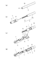
- FIG. 2 is a schematic diagram for explaining a process of crimping an electric wire with a waterproof plug inserted into a terminal.
- FIG. 2 (a) shows a state in which the end of the electric wire is cut
- FIG. FIG. 2 (c) shows a state immediately before the waterproof plug is inserted into the electric wire with the tip end portion of the core wire exposed
- FIG. 2 (c) is just before crimping the terminal (crimping the terminal) to the electric wire with the waterproof plug inserted.
- FIG. 2D shows a state where the crimping of the electric wire to the terminal is completed.
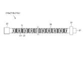
- FIG. 3 is a partial cross-sectional view of a waterproof plug magazine in which a plurality of waterproof plugs are loaded in a holder.
- FIG. 4 is a view showing a state when the waterproof plug is loaded in the holder.
- FIG. 5 is a perspective view showing the entirety of the waterproof plug feeder according to the embodiment of the present invention.
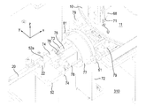
- FIG. 6 is a partially enlarged view in which the periphery of the loading mechanism in FIG. 5 is enlarged.
- FIG. 7 is a view showing an example of a waterproof plug constituting the waterproof plug magazine shown in FIG.
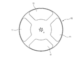
- FIG. 8 is a plan view of the component tray shown in FIG.
- FIG. 9 is a diagram in which some components are not shown in FIG. 6 in order to explain the loading mechanism.
- FIG. 9 is a diagram in which some components are not shown in FIG. 6 in order to explain the loading mechanism.
- FIG. 10 is a partially enlarged view enlarging the part moving part in FIG.
- FIG. 11 is a plan view (top view) of the waterproof plug supplier shown in FIG.
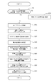
- FIG. 12 is a flowchart showing a processing flow when the waterproof plug supplier shown in FIG. 5 forms the waterproof plug magazine.
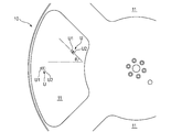
- FIG. 13 is a view for explaining the inclination ⁇ of the waterproof plug placed on the component tray.
- FIG. 14 is a view for explaining the movement of the apparatus when the waterproof plug supplier shown in FIG. 5 forms the waterproof plug magazine.
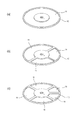
- FIG. 15 is a perspective view showing a modified example of the component tray
- FIG. 15A shows a first modified example of the component tray
- FIG. 15B shows a second modified example of the component tray
- FIG. (C) shows the 3rd modification of a component tray.
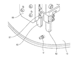
- FIG. 16 is a perspective view showing a modified example of the chuck.
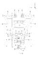
- a wire harness manufacturing system SYS including a component supply device (a supply device 200 to be described later) according to an embodiment of the present invention includes an assembly line 100 that sequentially assembles components of a wire harness, A plurality of (in this example, two) supply devices 200 that prepare the component parts so as to be supplied to the assembly line 100.
- the supply device 200 prepares component magazines 210a to 210c and 220a to 220d in which the components of the wire harness are loaded in the holder, as will be described later.
- the assembly line 100 may include a lot production line 110 and / or a set production line 120.
- the wire harness manufacturing system SYS can be applied to both the lot production line 110 and the set production line 120.
- the lot production line 110 (A line, B line and C line) manufactures three types of electric wires with different terminals for each type of waterproof plug (waterproof plugs A to C). A necessary amount is used for each of A to C), and three types of waterproof connectors A to C are manufactured independently for each type.
- the set production line 120 (D line) the required number of three types of electric wires with different terminals for each type of waterproof plugs (waterproof plugs A to C) is manufactured together.
- the waterproof connector D is manufactured by being assembled in the (housing D).
- the assembly line 100 (lot production line 110, set production line 120) shown in FIG. 1 is a part of an assembly line for manufacturing a wire harness. Therefore, the waterproof connectors A to D assembled in the assembly line 100 are sent to the next process for manufacturing the wire harness.
- the waterproof plug is a waterproof rubber plug for preventing water or the like from entering the terminal accommodating chamber of the housing.
- a process of crimping an electric wire with a waterproof plug attached (inserted) to a terminal will be briefly described with reference to FIG.
- the electric wire W in which the core wire W1 is covered with the insulating coating W2 is cut into a predetermined length (a different length depending on the specifications of the wire harness).
- the tip end portion of the core wire W1 is exposed by removing (peeling) the tip end portion of the insulating coating W2.
- the waterproof plug U is inserted in the electric wire W from which the tip end portion of the core wire W1 is exposed.
- the waterproof plug U has a stepped cylindrical shape having a small diameter portion U1 and a large diameter portion U2.
- the waterproof plug U is inserted into the electric wire W from the large diameter portion U2 side.
- the exposed core wire W1 and insulating coating W2 are covered by the small diameter portion U1 and the large diameter portion U2 of the waterproof plug U, respectively.
- the terminal T is a female terminal, the electric wire connection part T1 which receives the other male terminal (illustration omitted), and the 1st crimping
- the electric wire A, electric wire B, and electric wire C are different in type (for example, wire diameter, length, material, etc.).
- the waterproof plug A, the waterproof plug B, and the waterproof plug C are different in type (for example, the size of the diameter, the length, the surface shape, and the material).
- the housing A, the housing B, the housing C, and the housing D are different in type (for example, shape, material, type and number of electric wires with terminals to be inserted, and the like).
- the electric wire A is cut to a predetermined length, the tip end portion of the core wire of the electric wire A is exposed, and then the waterproof plug A is inserted into the electric wire A where the tip end portion of the core wire is exposed, and then the waterproof plug A terminal is crimped to the electric wire A into which A is inserted.
- the terminal is crimped after the waterproof plug B is inserted into the electric wire B, and the terminal is crimped after the waterproof plug C is inserted into the electric wire C.
- the electric wire A with the terminal crimped is assembled to the housing A (the terminal of the electric wire A is inserted into the terminal accommodating chamber of the housing A), and the waterproof connector A is manufactured.
- the electric wires A, B, and C with the terminals crimped are assembled to the housing B (the terminals of the electric wires A, B, and C are inserted into the terminal accommodating chamber of the housing B), and the waterproof connector B is manufactured.
- the electric wires B and C whose terminals are crimped are assembled into the housing C (the terminals of the electric wires B and C are inserted into the terminal accommodating chamber of the housing C), and the waterproof connector C is manufactured.
- electric wires A, B, and C whose terminals are crimped are mutually used in a plurality of A lines, B lines, and C lines.
- the assembly line 100 uses only the electric wire A with the terminal crimped in the A line, uses only the electric wire B with the terminal crimped in the B line, and the electric wire C with the terminal crimped in the C line. May be configured to use only.
- the electric wires A, B, and C are each cut to a predetermined length, and the leading ends of the core wires of the electric wires A, B, and C are exposed, and then the electric wires A and B that are exposed at the leading end of the core wire.
- C are respectively inserted into the waterproof plugs A, B, C, and then terminals are crimped to the electric wires A, B, C into which the waterproof plugs A, B, C are inserted, respectively. That is, the electric wires A, B, and C whose terminals are crimped are manufactured together.
- the electric wires A, B, C with the terminals crimped are inserted into the corresponding terminal insertion holes of the housing D, and the waterproof connector D is manufactured.
- the waterproof plug magazines 210a to 210c formed by the waterproof plug feeder 210 are supplied to the corresponding waterproof plug insertion process, respectively.
- the housing magazines 220a to 220d formed by the housing feeder 220 are respectively supplied to the terminal insertion process into the corresponding housing.
- the waterproof plug magazines 210a to 210c indicate holders in which a plurality of waterproof plugs of the same type are loaded in a row with their directions aligned in the same direction (see FIG. 3).
- the housing magazines 220a to 220d indicate holders in which a plurality of housings of the same type are loaded in a row with their directions aligned in the same direction (not shown).
- the waterproof plug magazines 210a to 210c will be briefly described with reference to FIG. 3 and FIG.
- the same kind of resin is placed in a cylindrical holder 20 having a circular cross section made of resin that can be easily deformed.
- a plurality of waterproof plugs U are loaded in a row with their directions aligned in the same direction.
- the waterproof plug magazine 210 a is configured such that each waterproof plug U is directed from the insertion port 21 (opening) on one end side of the holder 20 toward the small diameter portion U1 in the insertion direction by a waterproof plug supply unit 210 described later. In this state, it is formed by being inserted into the holder 20 sequentially.
- a fixing jig 22 is provided in the vicinity of the insertion port 21 of the holder 20. As will be described later, the fixing jig 22 is used when mounting and fixing the holder 20 to a predetermined location of the waterproof plug feeder 210 in order to form the waterproof plug magazine 210a.
- a cover 23 is provided in the opening on the other end side of the holder 20. The cover 23 has a function of preventing the waterproof plug U loaded in the holder 20 from dropping from the opening on the other end side of the holder 20.
- the waterproof plug supplier 210 forms a plurality of types of waterproof plug magazines 210a to 210c for each type of waterproof plug.
- the waterproof plug feeder 210 includes a waterproof plug magazine 210a loaded with only a plurality of waterproof plugs A, a waterproof plug magazine 210b loaded with only a plurality of waterproof plugs B, and a plurality of waterproof plugs C only.
- the loaded waterproof plug magazine 210c is formed.
- the formed waterproof plug magazines 210a to 210c are removed from the waterproof plug supply unit 210, and the corresponding line in the state of the waterproof plug magazine alone (in a state independent of both the waterproof plug supply unit 210 and the assembly line 100). Are supplied respectively.
- the waterproof plug magazine 210a is supplied to the waterproof plug insertion process of lines A and D
- the waterproof plug magazine 210b is supplied to the waterproof plug insertion process of lines B and D
- the waterproof plug magazine 210c is supplied to the lines C and D. Supplied to the waterproof plug insertion process.
- each type of waterproof plug magazine 210a to 210c formed by the waterproof plug supply unit 210 corresponds to the waterproof plug supply unit 210 in a state independent of both the assembly line 100 and the waterproof plug supply unit 210. Delivered to the corresponding process on the line. The removal of the waterproof plug from the waterproof plug magazine on each line and the supply of the waterproof plug magazine to each assembly line may be performed automatically using the device or manually. Good.
- the waterproof plug magazines 210a to 210c have been described above. However, the same applies to the housing magazines 220a to 220d. That is, the housing feeder 220 forms a plurality of types of housing magazines 220a to 220d for each type of housing.
- the housing feeder 220 includes a housing magazine 220a loaded with only a plurality of housings A, a housing magazine 220b loaded with only a plurality of housings B, a housing magazine 220c loaded with only a plurality of housings C, and A housing magazine 220d loaded with only a plurality of housings D is formed.
- Each type of formed housing magazine 220a-220d is removed from the housing feeder 220 and becomes a corresponding line in the state of the housing magazine alone (in a state independent of both the housing feeder 220 and the assembly line 100). Supplied respectively.
- the housing magazine 220a is supplied to the terminal insertion process for line A
- the housing magazine 220b is supplied to the terminal insertion process for line B
- the housing magazine 220c is supplied to the terminal insertion process for line C
- the housing magazine 220d is It is supplied to the terminal insertion process for line D.
- each type of housing magazine 220a to 220d formed by the housing feeder 220 corresponds to a corresponding line from the housing feeder 220 in a state independent of both the assembly line 100 and the housing feeder 220. Delivered to the process.
- the removal of the housing from the housing magazine on each line and the supply of the housing magazine to each assembly line may be performed automatically using an apparatus or may be performed manually.
- the waterproof plug feeder 210 can continue to form and prepare the waterproof plug magazines 210a to 210c regardless of the operation state of the assembly line 100 (whether the assembly line 100 is operating or stopped). Thus, the waterproof plug magazines 210a to 210c can be stocked during the period when the assembly line 100 is stopped due to some trouble or the like, so as to prepare for future demand for the waterproof plug magazines 210a to 210c. The same applies to the housing feeder 220.
- the waterproof plug feeder 210 corresponds to the number of consumptions per unit time in the assembly line 100 and the number of manufactured waterproof plug magazines 210a to 210c per unit time for each type of waterproof plugs A to C.
- Waterproof plug magazines 210a to 210c can be formed and prepared. As a result, the waterproof plug magazines 210a to 210c can be manufactured for each type of the waterproof plugs A to C according to the actual consumption number of the waterproof plugs A to C. The same applies to the housing feeder 220.
- the wire harness manufacturing system SYS including the component supply device 200 according to the embodiment of the present invention has been described above with reference to FIGS.
- the configuration of the waterproof plug feeder 210 will be described in detail with reference to FIGS.
- the housing supply machine 220 can be comprised similarly to the waterproof plug supply machine 210, the description is abbreviate
- the waterproof plug feeder 210 is provided on the upper surface 310 of the movable work table 300. Therefore, the waterproof plug feeder 210 can be appropriately moved with respect to the arrangement of the lines A to D.
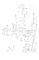
- the waterproof plug feeder 210 includes a component tray 10 on which the waterproof plug U is mounted, the above-described holder 20 (see FIGS. 3 and 4) used for forming the waterproof plug magazine, and the waterproof plug U from the component tray 10. And a loading mechanism 40 that loads the waterproof plug U disposed in the vicinity of the insertion port 21 of the holder 20 into the holder 20 to form a waterproof plug magazine.
- a loading mechanism 40 that loads the waterproof plug U disposed in the vicinity of the insertion port 21 of the holder 20 into the holder 20 to form a waterproof plug magazine.
- the component tray 10 is a disk-shaped member made of resin.
- the component tray 10 is circumferentially moved along the xy plane at a position above the upper surface 310 by a predetermined distance by a stay 51 that rises upward (z-axis positive direction) from the center portion of the upper surface 310 of the work table 300. It is fixed to be rotatable. Adjustment of the direction of the circumferential direction of the component tray 10 may be performed automatically using an apparatus, and may be performed manually.
- a plurality of grooves 11 are formed on the upper surface of the component tray 10.
- four identical grooves 11 are independently formed at equal intervals in the circumferential direction.
- a plurality of types of waterproof plugs corresponding to the specifications of the wire harness are placed in different types.
- the circumference of the component tray 10 is such that each of the four grooves 11 is located on the x-axis positive direction side, the x-axis negative direction side, the y-axis positive direction side, and the y-axis negative direction side.
- selection groove Only the waterproof plugs that have been adjusted in the direction and are placed in the groove 11 (hereinafter referred to as “selection groove” in particular) positioned on the negative side of the x-axis are used for forming the waterproof plug magazine.
- the insertion port 21 (see also FIGS. 3 and 4) of the holder 20 stands upward from the edge on the x-axis negative direction side of the upper surface 310 of the work table 300.
- the fixing jig 22 (see also FIGS. 3 and 4) described above is detachably attached to the mounting portion 52a by being inserted into a mounting portion 52a (a through hole (not shown) extending in the x-axis direction) provided on the upper surface of the stay 52. It is fixed to. Thereby, the edge part of the one end side of the holder 20 is being fixed to the attaching part 52a so that attachment or detachment is possible.
- the transport mechanism 30 includes a camera 31, a drive unit 32, and a component moving unit 33.
- the camera 31 is fixedly arranged at a position above the groove 11 (selection groove) of the component tray 10 by a stay (not shown) fixed to the upper surface 310 of the work table 300.
- the camera 31 photographs the waterproof plug U placed in the groove 11 (selection groove) from above.
- the drive unit 32 is a part related to the operation of moving a suction nozzle 68 (to be described later) for holding the waterproof plug U along the xy plane.
- a suction nozzle 68 to be described later
- a configuration related to the drive unit 32 will be described.
- a pair of first rails 54 extending in parallel with a predetermined distance from each other along the x-axis direction is a peripheral portion of the component tray 10 on the upper surface 310 of the work table 300.
- a plurality of stays 53 that rise upward from the top of the component tray 10 are fixed to a position above the component tray 10.
- the first moving body 55 is movable in the x-axis direction (corresponding to the “first direction” of the present invention) while being restrained by the pair of first rails 54. It is provided so as to straddle the rail 54.
- a second rail 56 extending in the y-axis direction (corresponding to the “second direction” of the present invention) is provided on the upper surface of the first moving body 55.
- a second moving body 57 is provided on the second rail 56 so as to be movable in the y-axis direction while being restrained by the second rail 56. As a result, the second moving body 57 can arbitrarily move along the xy plane. As will be described later, the suction nozzle 68 is indirectly fixed to the second moving body 57.
- One end portions of a pair of rod-shaped first drive arms 58 are coupled to both end portions in the y-axis direction of the second moving body 57 so as to be relatively rotatable along the xy plane.
- One end of a pair of rod-like second drive arms 59 is coupled to the other ends of the pair of first drive arms 58 so as to be relatively rotatable along the xy plane.
- a pair of electric motors 62 is fixed to stays 61 that rise upward from the edge on the x-axis positive direction side of upper surface 310 of worktable 300 so as to be arranged at predetermined intervals along the y-axis direction. .
- the motor shafts 63 of the pair of electric motors 62 protrude from the upper surface of the stay 61 toward the z-axis positive direction.
- the other end portions of the pair of second drive arms 59 are integrally connected to the pair of motor shafts 63, respectively.
- the drive unit 32 is configured as described above. As a result, by individually adjusting the rotation angles of the motor shafts 63 of the pair of electric motors 62, the second moving body 57 is driven from the pair of first drive arms 58 in the x-axis direction and the y-axis direction. A force is applied, and the position of the second moving body 57 on the xy plane can be arbitrarily adjusted.
- the component moving unit 33 is related to the operation of moving the suction nozzle 68 for holding the waterproof plug U along the z-axis direction and the operation of rotating the suction nozzle 68 extending in the z-axis direction around its axis. It is a part to do.
- a configuration related to the component moving unit 33 will be described.
- the stay 64 is fixed to the second moving body 57 so as to extend in the negative x-axis direction.
- An electric motor 65 is fixed to the stay 64.
- a motor shaft (not shown) of the electric motor 65 protrudes from the lower surface of the stay 64 in the negative z-axis direction.
- An L-shaped bracket 66 is integrally connected to the motor shaft of the electric motor 65.
- a rod-like suction nozzle 68 is provided at a hanging portion extending in the negative z-axis direction of the bracket 66 via a drive mechanism 67 so as to be relatively movable along the z-axis direction (corresponding to the “third direction” of the present invention). It has been.
- the drive mechanism 67 By controlling the drive mechanism 67, the position of the suction nozzle 68 in the z-axis direction with respect to the bracket 66 (in other words, the second moving body 57) can be adjusted.
- the axis of the suction nozzle 68 is positioned coaxially with the axis of the motor shaft of the electric motor 65. Therefore, by adjusting the rotation angle of the motor shaft of the electric motor 65, the suction nozzle 68 can be rotated around its axis (in the xy plane), and the position of the suction nozzle 68 in the rotation direction can be adjusted. It has become.
- a through hole 69 is formed along its axis.
- One end of a suction hose (not shown) is attached to the upper end of the through hole 69, and a suction vacuum pump (not shown) is connected to the other end of the hose.
- the lower end port of the through hole 69 functions as the suction port 71.
- the transport mechanism 30 has been described above. Next, a configuration related to the loading mechanism 40 will be described.
- a shaft 72 having a rectangular cross section (square) has an x-axis on a stay 72 that stands upward from a portion between the component tray 10 and the stay 52 on the upper surface 310 of the work table 300. It is fixed so as to extend in the negative direction and to be appropriately rotatable around the axis. The adjustment of the position of the shaft 73 in the rotational direction may be performed automatically using the apparatus or may be performed manually.
- FIG. 9 is a diagram in which the description of the stay 52 is omitted in FIG. 6 for convenience of explanation.
- the bracket 74 is fixed so as to extend in the negative x-axis direction at each of the four edge portions corresponding to the four sides at the tip end portion (end portion in the negative z-axis direction) of the shaft 73.
- Each bracket 74 is formed with a through-hole 75 extending in the x-axis direction at the x-axis negative direction side portion, and is continuous from the through-hole 75 in the x-axis positive direction at the x-axis positive direction side portion.
- a groove portion 76 that extends and opens upward is formed.
- the waterproof plug U carried by the suction nozzle 68 is placed in the groove 76.
- the four brackets 74 correspond to the four grooves 11 of the component tray 10, respectively. That is, the inner diameter of each through-hole 75 has a size corresponding to the maximum outer diameter of the waterproof plug U placed in the corresponding groove 11 among the four grooves 11 of the component tray 10. Therefore, in this example, the inner diameters of the through holes 75 of the four brackets are different.
- each of the four brackets 74 is positioned on the y-axis positive direction side, the y-axis negative direction side, the z-axis positive direction side, and the z-axis negative direction side.
- the position in the rotation direction is adjusted, and only the bracket 74 (hereinafter referred to as “selection bracket” in particular) located on the positive z-axis direction side is used for forming the waterproof plug magazine.
- the bracket 74 (selection bracket) is disposed close to the x-axis positive direction side of the mounting portion 52a of the stay 52 described above, and the through hole 75 of the bracket 74 (selection bracket) is provided with the mounting portion. It arrange
- a moving member 77 having an outer peripheral shape having a stepped cylindrical shape is inserted into the shaft 73 so as to be relatively movable in the x-axis direction with respect to the shaft 73 and not relatively rotatable. From the end surface of the moving member 77 on the x-axis negative direction side, the four push-in bars 78 are fixed so as to protrude in the x-axis negative direction toward the groove portions 76 of the corresponding bracket 74, respectively.
- a push bar 78 (hereinafter, particularly “selective push”) corresponding to the bracket 74 (selection bracket).
- the front end surface of the bar is called a waterproof plug U placed in the groove 76 of the bracket 74 (selection bracket) in the negative direction of the x-axis so that the waterproof plug U can be loaded into the holder 20. It has become.
- a pair of drive mechanisms 79 capable of adjusting the positions of the pair of gripping members 81 in the x-axis direction are fixed to the stay 72.
- the pair of gripping members 81 grips the flange portion on the x-axis positive direction side of the moving member 77. Therefore, by controlling the pair of drive mechanisms 79, the position of the moving member 77 in the x-axis direction can be adjusted.
- the waterproof plug U placed in the groove 76 of the bracket 74 (selection bracket) can be pushed in by the selective push bar 78 in the negative x-axis direction.
- the pair of electric motor 62, electric motor 65, drive mechanism 67, drive mechanism 79, and vacuum pump described above are controlled by a control device (microcomputer) (not shown).
- a control device microcomputer (not shown).
- the configuration of the waterproof plug feeder 210 has been described above.
- a plurality of waterproof plugs U corresponding to the waterproof plug magazine to be formed are placed in the groove 11 (selection groove) of the component tray 10, and the holder 20 and the bracket 74 ( It is necessary to switch the selection bracket and the selection push-in bar 78) to the one corresponding to the waterproof plug U of that type.
- a waterproof plug U having a stepped cylindrical shape having a small diameter portion U1 and a large diameter portion U2 is used. .
- each waterproof plug U is sequentially inserted into the holder 20 with the small diameter portion U ⁇ b> 1 side directed in the insertion direction (x-axis negative direction).
- step S5 it is determined whether or not the suction nozzle 68 is in the initial position.
- the initial position refers to a position where the suction nozzle 68 is disposed above a groove 76 (hereinafter also referred to as “magazine insertion slot”) of the bracket 74 (selected bracket) as shown in FIG.
- step S5 If the suction nozzle 68 is in the initial position (when determined “Yes” in step S5), the process proceeds directly to step S15. On the other hand, when the suction nozzle 68 is not in the initial position (when “No” is determined in Step S5), the suction nozzle 68 is moved to the initial position in Step S10, and then the process proceeds to Step S15.
- step S15 a plurality of waterproof plugs U placed in the groove 11 (selection groove) of the component tray 10 are photographed by the camera 31.
- the camera 31 is photographed when the suction nozzle 68 is in the initial position when the drive unit 32 and the component moving unit 33 are out of the photographing range of the camera 31. It is based on the fact that the drive unit 32 and the component moving unit 33 do not interfere with the photographing.
- step S20 pattern matching is performed based on the photographed image.
- pattern matching refers to an operation of specifying the positions (xy coordinates) of the plurality of waterproof plugs U placed in the groove 11 (selection groove).
- step S25 based on the pattern matching result, the waterproof plug U to be gripped is determined.
- step S30 the determined inclination ⁇ of the waterproof plug U is specified.
- the inclination ⁇ refers to the direction in which the waterproof plug U is placed in the magazine insertion slot (the direction in which the small diameter portion U1 side faces the negative x-axis direction), and the determined direction of the waterproof plug U. Refers to the angle formed by.
- step S35 the suction nozzle 68 is moved along the xy plane to the position just above the determined waterproof plug U while being rotated by an angle ⁇ (see (1) in FIG. 14). Subsequently, in step S40, the suction nozzle 68 is lowered in the negative z-axis direction (see (2) in FIG. 14). As a result, the suction port 71 of the suction nozzle 68 is positioned immediately above the determined waterproof plug U. In this state, the determined waterproof plug U is sucked into the suction port 71 of the suction nozzle 68.
- step S45 the suction nozzle 68 is moved to the initial position while being reversely rotated by the angle ⁇ (see (3) in FIG. 14).
- step S50 the suction nozzle 68 is lowered in the negative z-axis direction (see (4) in FIG. 14).
- the suction port 71 of the suction nozzle 68 is positioned immediately above the magazine insertion port (groove 76).
- the waterproof plug U adsorbed to the suction port 71 of the suction nozzle 68 is opened. Thereafter, the suction nozzle 68 is returned to the initial position.
- step S55 the waterproof plug U is loaded into the holder 20 (magazine) by pushing the waterproof plug U placed in the magazine insertion slot (groove 76) by the selection push-in bar 78.
- the predetermined number of waterproof plugs U of the same type in the holder 20 are aligned in the same direction.
- the loaded waterproof plug magazine (for example, the waterproof plug magazines 210a to 210c in FIG. 1) is completed.
- the completed waterproof plug magazine is removed from the waterproof plug feeder 210. Thereafter, in order to form the next waterproof plug magazine, the component tray 10 is rotated so that the groove 11 on which the waterproof plug U of the type corresponding to the next waterproof plug magazine is placed becomes the groove 11 (selection groove). The shaft 73 is rotated so that the bracket 74 (and the push-in bar 78) corresponding to the type of waterproof plug U becomes the bracket 74 (selection bracket and the selective push-in bar 78). A device corresponding to the type of waterproof plug U is attached to the waterproof plug feeder 210. Then, the next waterproof plug magazine is completed by performing the above-described process again.
- the camera 31 is photographed with the suction nozzle 68 in the initial position, but the drive unit 32 and the component moving unit 33 are located outside the photographing range of the camera 31 ( That is, as long as the drive unit 32 and the component moving unit 33 do not interfere with the shooting), the camera 31 may perform shooting with the suction nozzle 68 in a position other than the initial position.
- the photographing of the camera 31 (the process of step S15) may be performed in the middle of returning the suction nozzle 68 to the initial position.
- the process of step S20, S25, and S30 may be performed following the process of step S15 in the middle of the suction nozzle 68 returning to the initial position.
- the waterproof plug supply device 210 loads the waterproof plug U into the holder 20 while aligning the waterproof plug U in a predetermined direction based on the image taken by the camera 31.
- 210a to 210c can be formed.
- the waterproof plug supply unit 210 can form a plurality of types of waterproof plug magazines 210a to 210c that differ depending on the type of the waterproof plugs U as required. It is.
- the waterproof plug feeder 210 is not a dedicated device for each type of waterproof plug U, but a general-purpose device that can handle various types of waterproof plug U. That is, there is a one-to-many relationship between the type of the waterproof plug U and the waterproof plug feeder 210.
- the waterproof plug U can be supplied to the assembly line 100 of the wire harness through the waterproof plug magazine formed in this way. Therefore, compared with the conventional device described in the background art section, the number of devices can be reduced, so that the cost of the device itself can be reduced. Furthermore, since the waterproof plug magazines 210a to 210c may be used properly according to the specifications of the wire harness (without resetting the apparatus itself), the preparation cost of the assembly line 100 can be reduced. In other words, by using the waterproof plug feeder 210 and the waterproof plug magazines 210a to 210c, the assembly line 100 (and thus the entire manufacturing system) can be flexibly adapted to wire harnesses of various specifications. it can.
- the waterproof plug feeder 210 can reduce the manufacturing cost as much as possible even when various types of waterproof plug U are to be supplied to the assembly line 100.
- a component magazine is used for some components (eg, waterproof plugs and connector housings), and a device such as a conventional system supply device is used for other components (eg, terminals and clamps). You may prepare separately.
- the waterproof plug U on the tray 10 can be photographed by the camera 31 when the waterproof plug U is transported to the loading port (magazine insertion port) of the holder 20. Therefore, while placing the waterproof plug U at the magazine insertion slot, analyze the photographed image (the determination of the waterproof plug U to be transported to the magazine insertion slot and the inclination ⁇ for aligning the waterproof plug U). Etc.) can be performed. Therefore, photographing of the waterproof plug U and transportation of the waterproof plug U can be performed efficiently.
- the waterproof plug magazine is detachable from the waterproof plug supply unit 210, the waterproof plug supply unit 210 can be indirectly connected to the assembly line 100 (via the waterproof plug magazine). Therefore, compared with the case where the apparatus and the assembly line are directly connected as in the conventional apparatus, even if the malfunction occurs in one of the apparatus and the assembly line 100 and the operation stops, the other operation can be continued. In other words, the waterproof plug magazine functions as a buffer for the entire system. Therefore, the stability of the manufacturing system can be improved.
- the waterproof plug feeder 210 continues to manufacture the waterproof plug magazine regardless of whether the assembly line 100 is operating or stopped. Accordingly, the waterproof plug magazine can be stocked during the period when the assembly line 100 is stopped due to some trouble or the like, so as to prepare for future demand for the waterproof plug magazine. Therefore, the stability of the manufacturing system can be improved.
- a plurality of types of waterproof plugs may be placed on the component tray 10 in a divided manner. Furthermore, a plurality of types of waterproof plugs may be placed without being divided into areas, and the types of waterproof plugs may be identified by pattern matching based on the captured image of the camera 31.
- a plurality of grooves 11 having the same shape (same area) are formed on the upper surface of the component tray 10.
- a plurality of grooves 11 having different shapes may be formed on the upper surface of the component tray 10.
- the wire harness manufacturing system SYS includes a plurality of supply devices 200 (specifically, the waterproof plug supply device 210 and the housing supply device 220) for the assembly line 100.
- a single supply device 200 (specifically, the waterproof plug supply device 210 or the housing supply device 220) may be provided for the assembly line 100.
- one stick-shaped suction nozzle 68 is used as the component chuck.
- a pair of gripping arms 82 with adjustable intervals may be used as the component chuck.
- the drive unit 32 that moves the suction nozzle 68 along the xy plane includes the first moving body 55, the second moving body 57, the first driving arm 58, and the second driving arm 59. It consists of However, any configuration may be adopted as the drive unit 32 as long as the suction nozzle 68 can be moved along the xy plane.
- waterproof plug magazines 210a to 210c and housing magazines 220a to 220d are used as examples of the parts magazine.
- a parts magazine may be prepared using parts (for example, a clamp, a corrugated tube, etc.) other than a waterproof plug and a housing.
- the transport mechanism (30) A camera (31) for photographing the components placed on the parts tray;
- a first movable body (55) that is movable while being restrained by a first rail (54) extending in a first direction that connects the component tray (10) and the loading port (76), and that intersects the first direction.
- a second moving body (57) movable while being restrained by a second rail (56) provided on the first moving body (55) so as to extend in two directions, and the second moving body (57) Driving arms (58, 59) for applying at least one driving force in the first direction and the second direction to the second moving body (57) according to the first direction and the second direction.
- a drive unit (32) capable of being moved along a defined moving plane;
- the component parts are placed in the component tray (( 10) to the loading port (76), Parts supply device.
- the parts magazine (210a to 210c) It is detachable from the component supply device (210). Parts supply device.
- the component tray (10) A partition room (11) capable of partitioning the component parts by type is provided, and the number of the specific component parts (waterproof plugs A to C) that can be accommodated in each of the partition rooms, and the specific component parts are
- the parts magazines (210a to 210c) to be loaded are configured to correspond to the number of manufactured units per unit time, Parts supply device.
- the manufacturing cost of the wire harness can be reduced as much as possible even when various types of components are to be supplied to the assembly line.
- the present invention having this effect is useful for a component supply apparatus.
Landscapes
- Engineering & Computer Science (AREA)
- Mechanical Engineering (AREA)
- Manufacturing & Machinery (AREA)
- Automatic Assembly (AREA)
- Manufacturing Of Electrical Connectors (AREA)
- Feeding Of Articles To Conveyors (AREA)
Abstract
La présente invention concerne un dispositif d'acheminement de composants (210) qui comprend : un plateau (10) de composants sur lequel est placé un composant (U) d'un faisceau de câbles ; un porte-composants (20) dans lequel est chargé le composant ; un mécanisme de transport (30) pour le transport du composant du plateau de composants à un port de charge (76) du porte-composants ; et un mécanisme de charge (40) dans lequel le composant disposé dans le port de charge est chargé sur le porte-composant, formant un magasin de composants. Sur la base d'une image capturée par une caméra (31), le mécanisme de transport transporte le composant du plateau de composants au port de charge de telle manière que l'orientation du composant disposé sur le port de charge est alignée dans une direction préétablie.
Priority Applications (1)
| Application Number | Priority Date | Filing Date | Title |
|---|---|---|---|
| CN201780026867.6A CN109155170B (zh) | 2016-05-31 | 2017-04-28 | 部件供给装置 |
Applications Claiming Priority (2)
| Application Number | Priority Date | Filing Date | Title |
|---|---|---|---|
| JP2016-109041 | 2016-05-31 | ||
| JP2016109041A JP6367861B2 (ja) | 2016-05-31 | 2016-05-31 | 部品供給装置 |
Publications (1)
| Publication Number | Publication Date |
|---|---|
| WO2017208716A1 true WO2017208716A1 (fr) | 2017-12-07 |
Family
ID=60479270
Family Applications (1)
| Application Number | Title | Priority Date | Filing Date |
|---|---|---|---|
| PCT/JP2017/017011 Ceased WO2017208716A1 (fr) | 2016-05-31 | 2017-04-28 | Dispositif d'acheminement de composants |
Country Status (3)
| Country | Link |
|---|---|
| JP (1) | JP6367861B2 (fr) |
| CN (1) | CN109155170B (fr) |
| WO (1) | WO2017208716A1 (fr) |
Families Citing this family (4)
| Publication number | Priority date | Publication date | Assignee | Title |
|---|---|---|---|---|
| JP6499742B1 (ja) | 2017-11-09 | 2019-04-10 | 株式会社アマダホールディングス | 物品仕分け装置 |
| CN108311859B (zh) * | 2018-01-22 | 2019-12-31 | 安徽慧视金瞳科技有限公司 | 一种基于视觉检测技术的绝缘子自动装配方法 |
| CN110355547B (zh) * | 2019-07-29 | 2020-10-23 | 浙江理工大学 | 一种扭簧的分料输送机 |
| CN112573141B (zh) * | 2020-12-14 | 2022-10-11 | 无锡威孚奥特凯姆精密机械有限公司 | 一种小连接杆摆料机 |
Citations (3)
| Publication number | Priority date | Publication date | Assignee | Title |
|---|---|---|---|---|
| JPH09115640A (ja) * | 1995-10-20 | 1997-05-02 | Harness Sogo Gijutsu Kenkyusho:Kk | ワイヤーハーネスの製造におけるコネクタ供給方法及びその装置 |
| JPH10208844A (ja) * | 1997-01-28 | 1998-08-07 | Harness Sogo Gijutsu Kenkyusho:Kk | ワイヤーハーネス用コネクタ端子の実装装置 |
| JP2015076198A (ja) * | 2013-10-07 | 2015-04-20 | 矢崎総業株式会社 | ワイヤハーネス部品移送装置、端子圧着電線製造装置、ワイヤハーネス部品移送方法、端子圧着電線の製造方法 |
Family Cites Families (4)
| Publication number | Priority date | Publication date | Assignee | Title |
|---|---|---|---|---|
| JP2014077755A (ja) * | 2012-10-12 | 2014-05-01 | Murata Mfg Co Ltd | 電子部品の搬送装置および電子部品の搬送方法 |
| JP5567239B1 (ja) * | 2013-02-23 | 2014-08-06 | 古河電気工業株式会社 | 接続構造体の製造方法、及び接続構造体の製造装置 |
| JP2015043268A (ja) * | 2013-08-26 | 2015-03-05 | 住友電装株式会社 | ワイヤハーネスの製造装置及びその製造方法 |
| WO2015053284A1 (fr) * | 2013-10-07 | 2015-04-16 | 矢崎総業株式会社 | Dispositif et procédé de transport de composants de faisceau de fils, dispositif et procédé de production de cosses à sertir |
-
2016
- 2016-05-31 JP JP2016109041A patent/JP6367861B2/ja active Active
-
2017
- 2017-04-28 CN CN201780026867.6A patent/CN109155170B/zh active Active
- 2017-04-28 WO PCT/JP2017/017011 patent/WO2017208716A1/fr not_active Ceased
Patent Citations (3)
| Publication number | Priority date | Publication date | Assignee | Title |
|---|---|---|---|---|
| JPH09115640A (ja) * | 1995-10-20 | 1997-05-02 | Harness Sogo Gijutsu Kenkyusho:Kk | ワイヤーハーネスの製造におけるコネクタ供給方法及びその装置 |
| JPH10208844A (ja) * | 1997-01-28 | 1998-08-07 | Harness Sogo Gijutsu Kenkyusho:Kk | ワイヤーハーネス用コネクタ端子の実装装置 |
| JP2015076198A (ja) * | 2013-10-07 | 2015-04-20 | 矢崎総業株式会社 | ワイヤハーネス部品移送装置、端子圧着電線製造装置、ワイヤハーネス部品移送方法、端子圧着電線の製造方法 |
Also Published As
| Publication number | Publication date |
|---|---|
| JP2017216140A (ja) | 2017-12-07 |
| JP6367861B2 (ja) | 2018-08-01 |
| CN109155170B (zh) | 2020-03-17 |
| CN109155170A (zh) | 2019-01-04 |
Similar Documents
| Publication | Publication Date | Title |
|---|---|---|
| JP6475664B2 (ja) | ワイヤハーネスの製造システム、及び、ワイヤハーネスの製造方法 | |
| JP6367861B2 (ja) | 部品供給装置 | |
| CN105359639B (zh) | 元件安装装置 | |
| JP6507189B2 (ja) | 電線処理装置及び電線処理方法 | |
| KR101753018B1 (ko) | 와이어 하네스의 제조 장치 및 그 제조 방법 | |
| WO2014181729A1 (fr) | Dispositif et procédé de fabrication de fils sertis par borne | |
| CN110120620B (zh) | 线束插头自动化加工方法 | |
| WO2015053284A1 (fr) | Dispositif et procédé de transport de composants de faisceau de fils, dispositif et procédé de production de cosses à sertir | |
| CN103491760B (zh) | 元件安装装置及元件安装方法 | |
| US10039218B2 (en) | Electronic circuit component mounting system | |
| JP2921383B2 (ja) | コネクタハウジング供給装置 | |
| JP2017216141A (ja) | 部品受け渡し装置及びそれを備えるワイヤハーネスの製造装置 | |
| US20170133809A1 (en) | Device and method for automatically mounting a connector-housing | |
| JP6195468B2 (ja) | 端子圧着電線製造装置及び端子圧着電線の製造方法 | |
| JP4748065B2 (ja) | 圧着端子組付け方法および端子圧着方法並びに端子圧着設備 | |
| JP2016115667A (ja) | プラグ筐体に装着するための装置および方法 | |
| US6321445B1 (en) | Apparatus and method of manufacturing an automobile wiring harness having a predetermined wiring route | |
| JP2017204402A (ja) | ワイヤハーネスの製造ライン | |
| CN104275601B (zh) | 鼠标的电路模组的供给装置 | |
| JP6335467B2 (ja) | ワイヤハーネス部品移送装置、端子圧着電線製造装置、ワイヤハーネス部品移送方法、端子圧着電線の製造方法 | |
| CN111788881B (zh) | 安装装置以及安装装置的控制方法 | |
| JP3127808B2 (ja) | 端子付き電線の挿入装置 | |
| JP6968569B2 (ja) | 部品実装装置 | |
| JP6705697B2 (ja) | 電線付きコネクタの製造装置 | |
| CN114346696B (zh) | 长度不同的多种规格导管自动组装机 |
Legal Events
| Date | Code | Title | Description |
|---|---|---|---|
| NENP | Non-entry into the national phase |
Ref country code: DE |
|
| 121 | Ep: the epo has been informed by wipo that ep was designated in this application |
Ref document number: 17806275 Country of ref document: EP Kind code of ref document: A1 |
|
| 122 | Ep: pct application non-entry in european phase |
Ref document number: 17806275 Country of ref document: EP Kind code of ref document: A1 |