WO2017208797A1 - Système de commande de véhicule - Google Patents
Système de commande de véhicule Download PDFInfo
- Publication number
- WO2017208797A1 WO2017208797A1 PCT/JP2017/018234 JP2017018234W WO2017208797A1 WO 2017208797 A1 WO2017208797 A1 WO 2017208797A1 JP 2017018234 W JP2017018234 W JP 2017018234W WO 2017208797 A1 WO2017208797 A1 WO 2017208797A1
- Authority
- WO
- WIPO (PCT)
- Prior art keywords
- vehicle
- monitoring
- obstacle
- sensor
- speed
- Prior art date
- Legal status (The legal status is an assumption and is not a legal conclusion. Google has not performed a legal analysis and makes no representation as to the accuracy of the status listed.)
- Ceased
Links
Images




Classifications
-
- B—PERFORMING OPERATIONS; TRANSPORTING
- B61—RAILWAYS
- B61L—GUIDING RAILWAY TRAFFIC; ENSURING THE SAFETY OF RAILWAY TRAFFIC
- B61L23/00—Control, warning or like safety means along the route or between vehicles or trains
- B61L23/04—Control, warning or like safety means along the route or between vehicles or trains for monitoring the mechanical state of the route
- B61L23/041—Obstacle detection
-
- B—PERFORMING OPERATIONS; TRANSPORTING
- B60—VEHICLES IN GENERAL
- B60L—PROPULSION OF ELECTRICALLY-PROPELLED VEHICLES; SUPPLYING ELECTRIC POWER FOR AUXILIARY EQUIPMENT OF ELECTRICALLY-PROPELLED VEHICLES; ELECTRODYNAMIC BRAKE SYSTEMS FOR VEHICLES IN GENERAL; MAGNETIC SUSPENSION OR LEVITATION FOR VEHICLES; MONITORING OPERATING VARIABLES OF ELECTRICALLY-PROPELLED VEHICLES; ELECTRIC SAFETY DEVICES FOR ELECTRICALLY-PROPELLED VEHICLES
- B60L15/00—Methods, circuits, or devices for controlling the traction-motor speed of electrically-propelled vehicles
- B60L15/40—Adaptation of control equipment on vehicle for remote actuation from a stationary place
-
- B—PERFORMING OPERATIONS; TRANSPORTING
- B61—RAILWAYS
- B61L—GUIDING RAILWAY TRAFFIC; ENSURING THE SAFETY OF RAILWAY TRAFFIC
- B61L15/00—Indicators provided on the vehicle or train for signalling purposes
- B61L15/0062—On-board target speed calculation or supervision
-
- B—PERFORMING OPERATIONS; TRANSPORTING
- B61—RAILWAYS
- B61L—GUIDING RAILWAY TRAFFIC; ENSURING THE SAFETY OF RAILWAY TRAFFIC
- B61L23/00—Control, warning or like safety means along the route or between vehicles or trains
-
- B—PERFORMING OPERATIONS; TRANSPORTING
- B61—RAILWAYS
- B61L—GUIDING RAILWAY TRAFFIC; ENSURING THE SAFETY OF RAILWAY TRAFFIC
- B61L23/00—Control, warning or like safety means along the route or between vehicles or trains
- B61L23/08—Control, warning or like safety means along the route or between vehicles or trains for controlling traffic in one direction only
- B61L23/14—Control, warning or like safety means along the route or between vehicles or trains for controlling traffic in one direction only automatically operated
-
- B—PERFORMING OPERATIONS; TRANSPORTING
- B61—RAILWAYS
- B61L—GUIDING RAILWAY TRAFFIC; ENSURING THE SAFETY OF RAILWAY TRAFFIC
- B61L27/00—Central railway traffic control systems; Trackside control; Communication systems specially adapted therefor
- B61L27/20—Trackside control of safe travel of vehicle or train, e.g. braking curve calculation
Definitions
- the present invention relates to a vehicle control system, and is suitable for application to a vehicle control system that controls a vehicle traveling on a track.
- Patent Document 1 discloses an automatic train notification system that provides emergency information to passengers together with a driver in an emergency.
- the obstacle detection device detects an obstacle based on a video taken by a monitoring camera provided in the track or along the start, and receives a detection result from the obstacle detection device.
- the emergency information automatic notification device is configured to rank the urgency levels and notify the driver and passengers of emergency information according to the rank.
- patent document 2 the said train automatic notification system of patent document 1 has the subject that "it is not considered about the improvement in the safety and operation availability when the sensor laid on the ground fails."
- a vehicle control system is disclosed that can improve the safety and operation rate of a train as compared with the conventional case when a sensor laid on the ground breaks down.
- the present invention has been made in consideration of the above points, and enables vehicle control considering both safety and operation rate in vehicle operation even when the presence or absence of an obstacle on a track cannot be sufficiently detected. It intends to propose a vehicle control system.
- the present invention provides a vehicle control system for controlling the operation of the first vehicle traveling on the first track.
- This vehicle control system is a first vehicle that is installed in a first vehicle and can execute a monitoring operation for detecting the presence or absence of an obstacle at the predetermined point when the predetermined point on the first track is within the detection range.
- a sensor one or more second sensors installed at a predetermined location other than the first vehicle and capable of executing a monitoring operation for detecting the presence or absence of an obstacle at a predetermined point at a predetermined timing; and a second sensor
- a monitoring result collection unit that collects and stores the monitoring results of the monitoring operation, and a target speed of the first vehicle is determined based on the monitoring results stored in the monitoring result collection unit or the monitoring results of the monitoring operation by the first sensor
- a speed determining unit that controls the traveling speed of the first vehicle based on the target speed determined by the speed determining unit, and the speed determining unit is based on the first or second sensor.
- a risk evaluation unit that evaluates the degree of danger of existence and determines a risk rate of 1, and a speed command calculation unit that determines a target speed to be commanded to the speed control unit according to the risk rate determined by the risk evaluation unit It is characterized by having.
- FIG. (1) for demonstrating the operation example by the vehicle control system which concerns on 1st Embodiment.
- FIG. (2) for demonstrating the operation example by the vehicle control system which concerns on 1st Embodiment.
- FIG. (2) for demonstrating the operation example by the vehicle control system which concerns on 1st Embodiment.
- FIG. (2) for demonstrating the operation example by the vehicle control system which concerns on 1st Embodiment.
- FIG. (2) for demonstrating the structural example of the vehicle control system which concerns on 2nd Embodiment.
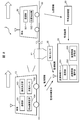
- FIG. 1 is a diagram for explaining a configuration example of a vehicle control system according to a first embodiment.
- the vehicle control system 1 according to the first embodiment as shown in FIG. 1, it is assumed that the vehicle 10 is applied to a railway transportation system that realizes transportation by traveling on a track 100 according to a predetermined operation plan. To explain.
- a vehicle 10 shown in FIG. 1 is a vehicle that travels on a track 100.
- the vehicle 10 is about to enter the section X1 of the track 100 with the direction from left to right as the traveling direction.
- the vehicle 10 includes a communication unit 101 that communicates with the outside, an in-vehicle sensor 102 that can detect the presence or absence of an obstacle within a predetermined range, and a speed for determining a target speed (details will be described later) of the vehicle 10.
- a determination unit 103 and a vehicle control device 104 that controls the traveling speed of the vehicle 10 based on the target speed are provided.
- the section X1 is an example of a “predetermined point (predetermined range)” that is a target for detecting the presence or absence of an obstacle in the present embodiment.
- the communication unit 101 can communicate data and signals with the outside of the vehicle 10 (in the case of FIG. 1, the communication unit 201 of the monitoring information server 20) by wireless communication, and is realized by a general wireless communication interface. can do.
- the in-vehicle sensor 102 is a sensor that can detect (or monitor) the presence or absence of an obstacle in a predetermined monitoring range, and a general obstacle sensor can be used. More specifically, the in-vehicle sensor 102 shown in FIG. 1 detects the presence or absence of an obstacle in the section X1 when the vehicle 10 traveling on the track 100 approaches the section X1 and the section X1 is within the monitoring range. To do. The result of detection by the in-vehicle sensor 102 is input to the speed determination unit 103 as a monitoring result.
- the timing at which a useful monitoring result can be output from the in-vehicle sensor 102 to the speed determining unit 103 is such that the vehicle 10 is sufficiently close to the section X1 and the section X1 falls within the detection distance of the in-vehicle sensor 102, and the fault in the section X1 It is after the monitoring operation for the presence or absence of objects. Therefore, even if a monitoring result is sent from the in-vehicle sensor 102 to the speed determination unit 103 at a timing before that, the content of the monitoring result is “undecided” with respect to the presence of an obstacle and the monitoring time.
- the speed determination unit 103 collects obstacle detection results (monitoring information, monitoring results) at predetermined points (for example, the section X1) by the sensors (vehicle sensor 102, ground sensor 30) included in the vehicle control system 1, and collects the collected data. Based on the information, the target speed when the vehicle 10 travels through the predetermined point can be determined.
- the speed determination unit 103 also has a function of requesting the monitoring information server 20 to provide the monitoring information stored in the monitoring information server 20 (monitoring information request).
- a speed determination unit 103 can be realized, for example, by a computer device configured with a CPU (Central Processing Unit), a memory, and the like. Details of the characteristic functional configuration of the speed determination unit 103 will be described later with reference to FIG.
- the vehicle control device 104 is a control device that controls the traveling speed of the vehicle 10, and for example, a vehicle control device that is generally used in a railway vehicle or the like can be used.
- the vehicle control device 104 can change the traveling speed of the vehicle 10 to an arbitrary speed, set an upper limit speed of the traveling speed of the vehicle 10, or stop the traveling vehicle 10 in particular.
- the traveling speed of the vehicle 10 is controlled so as not to exceed the target speed specified by the speed command (mainly deceleration control). )
- the monitoring information server 20 shown in FIG. 1 is a computer owned by an administrator of the vehicle control system 1, and is a monitoring information management that controls the communication unit 201 that performs communication with the outside and the monitoring information server 20. And a monitoring information storage unit 203 that stores monitoring information generated by the control of the monitoring information management unit 202.
- the monitoring information server 20 is installed in, for example, a vehicle control room or a station building through which the track 100 passes. Details of the control by the monitoring information management unit 202 will be described later.
- the monitoring information server 20 receives the monitoring result from the ground sensor 30, and generates and stores monitoring information based on the received monitoring result. In addition, it has a function of transmitting monitoring information to the vehicle 10 in response to a monitoring information provision request (monitoring information request) from the vehicle 10.
- the communication unit 201 can communicate data and signals with the outside of the monitoring information server 20 (in the case of FIG. 1, the communication unit 101 of the vehicle 10 and the ground sensor 30) by wireless communication or wired communication. It can be realized by a simple communication interface.
- the monitoring information management unit 202 receives a monitoring result from a sensor (ground sensor 30 in the case of FIG. 1) that monitors the presence or absence of an obstacle on the track 100 via the communication unit 201, and receives the monitoring information as monitoring information.
- a sensor ground sensor 30 in the case of FIG. 1
- the monitoring information stored in the monitoring information storage unit 203 is transmitted to the vehicle 10 via the communication unit 201.
- the monitoring information stored in the monitoring information storage unit 203 includes information indicating the presence / absence of an obstacle and information indicating the monitoring time when the monitoring is performed (refer to the monitoring information server 20 in FIG. 3 described later). .
- the monitoring information transmitted from the monitoring information server to the vehicle 10 does not have to be all the monitoring information stored in the monitoring information storage unit 203. For example, only the monitoring information related to the section X1 may be transmitted. Good. By transmitting only the necessary monitoring information in this way, an effect of shortening the time required for the process of determining the target speed by the speed determination unit 103 of the vehicle 10 can be expected.
- the monitoring information server 20 does not retransmit the monitoring information when there is monitoring information transmitted to the vehicle 10 at the time of the previous monitoring information request.
- the monitoring information stored in the information storage unit 203 only unprocessed (untransmitted) monitoring information may be transmitted to the vehicle 10.
- the monitoring information server 20 is configured to store monitoring results from a plurality of sensors as monitoring information (not shown, but a configuration in which a plurality of ground sensors 30 are installed is assumed). In this case, when unprocessed (untransmitted) monitoring information exists in a plurality of sensors, the monitoring information may be transmitted using only the monitoring result with the latest monitored time.
- the monitoring information storage unit 203 is a storage medium that stores monitoring information according to the control of the monitoring information management unit 202. When newly instructed to store monitoring information, the monitoring information storage unit 203 updates the monitoring information in such a manner that the monitoring information is added to the monitoring information stored in the past.
- An example of the monitoring information stored in the monitoring information storage unit 203 is shown in the monitoring information server 20 of FIG. 3 described later.
- a ground sensor 30 shown in FIG. 1 is a fixed sensor arranged at a predetermined point (which may be considered as a predetermined range, for example, section X1) on the trajectory 100 and can be detected at the predetermined point. It has a function of performing a monitoring operation for continuously detecting (or constantly detecting) the presence or absence of an obstacle and outputting (transmitting) the result of the monitoring operation to the monitoring information server 20 as a monitoring result.
- the monitoring information output from the ground sensor 30 to the monitoring information server 20 includes the detection result indicating the presence or absence of an obstacle and the monitoring time when the detection is performed.
- the output of the monitoring result by the ground sensor 30 is, for example, a monitoring operation that constantly detects the presence or absence of an obstacle in the section X1, and the monitoring information server 20 periodically collects the results of the monitoring operations as a monitoring result.
- a monitoring operation that periodically detects the presence or absence of an obstacle in the section X1 is performed, and a monitoring result is output to the monitoring information server 20 each time the monitoring operation is performed. There may be.
- each configuration of the vehicle control system 1 the types of obstacles monitored by the sensors (the ground sensor 30 and the vehicle-mounted sensor 102) are not particularly limited. Examples of obstacles that can be specifically monitored include falling rocks, landslides, or intrusions to railroad crossings, and these obstacles are based on environmental characteristics at the monitoring target point (section X1). The frequency of occurrence is different. Therefore, each sensor of the vehicle control system 1 may be provided with detection logic suitable for detecting the presence or absence of an obstacle that is most concerned according to the environmental characteristics of the monitored point (section X1). preferable.
- the types of obstacles as main detection targets may be dispersed by having each sensor have a different detection logic or detection mechanism. For example, if an optical sensor with a wide viewing angle is used, not only the section X1 but also other points can be monitored. Unlike the ground sensor 30 fixed on the ground, in the case of the in-vehicle sensor 102 installed in the vehicle 10, when the in-vehicle sensor 102 detects that there is an obstacle in the section X1, the vehicle 10 and the obstacle Is required to be able to sufficiently decelerate the vehicle 10 before the obstacle using the distance, the performance of the detection range (detection distance) of the in-vehicle sensor 102 is as described above. It is preferably long enough to ensure a “sufficient distance”. When the main detection targets are dispersed by the sensors in this way, it can be expected to detect various dangerous situations at the monitoring target point (section X1). Such variations can be similarly applied to other embodiments described later.
- FIG. 2 is a block diagram illustrating a main functional configuration example of the vehicle control system illustrated in FIG. 1.
- information input / output in the vehicle control system 1 shown in FIG. 1 is described, and in particular, a detailed configuration of the speed determining unit 103 is added.
- the speed determination unit 103 includes a position detection unit 105 that acquires position information of the vehicle 10, a monitoring information request unit 106 that requests the monitoring information server 20 to present monitoring information, and a predetermined point (for example, section X ⁇ b> 1). ), A risk evaluation unit 107 that determines a risk rate of the vehicle 10 and a speed command calculation unit 108 that determines a target speed (speed command value) of the vehicle 10 based on the risk rate.
- a position detection unit 105 that acquires position information of the vehicle 10
- a monitoring information request unit 106 that requests the monitoring information server 20 to present monitoring information
- a predetermined point for example, section X ⁇ b> 1
- a risk evaluation unit 107 that determines a risk rate of the vehicle 10
- a speed command calculation unit 108 that determines a target speed (speed command value) of the vehicle 10 based on the risk rate.
- the position detection unit 105 has a function of detecting the position of the vehicle 10, and outputs position information obtained by the detection to the monitoring information request unit 106. Specifically, the position detection unit 105 counts the number of rotations of wheels, for example, which is generally provided in a railway vehicle, and determines from a reference position (a position of a beacon installed on a track between stations or stations). The relative position of the vehicle 10 may be detected (calculated) by calculating the relative position of the vehicle 10, or the absolute position of the vehicle 10 may be detected (calculated) using a satellite positioning system such as GPS (Global Positioning System). ).
- GPS Global Positioning System
- the monitoring information request unit 106 receives the position information of the vehicle 10 from the position detection unit 105, and when the vehicle 10 approaches a predetermined distance from the section X1, for example, sends a monitoring information request via the communication unit 101 to the monitoring information server. 20 is notified.
- the monitoring information server 20 receives the monitoring information request, the monitoring information management unit 202 transmits the monitoring information stored in the monitoring information storage unit 203 to the vehicle 10, and the transmitted monitoring information is transmitted via the communication unit 101.
- the risk evaluation unit 107 To the risk evaluation unit 107.
- the risk evaluation unit 107 receives the monitoring information from the monitoring information server 20 and the monitoring result from the in-vehicle sensor 102, and determines the risk rate of the vehicle 10 related to the predetermined point (section X1) to be monitored.
- the “risk rate of the vehicle 10 related to the section X1” indicates the degree of risk that the passage of the vehicle 10 is hindered by an obstacle in the section X1. The higher the risk rate in the section X1, the higher the possibility that there will be an obstacle in the section X1 and hinder the passage of the vehicle 10. Details of the determination of the risk rate will be described later in (3).
- the risk rate determined by the risk evaluation unit 107 is output to the speed command calculation unit 108.
- the speed command calculation unit 108 determines a target speed corresponding to the risk rate based on the risk rate determined by the risk evaluation unit 107.
- the target speed means an upper limit target of the traveling speed allowed for the vehicle 10, and specifically corresponds to, for example, a speed command value shown in the speed command calculation unit 108 in FIG. Then, the speed command calculation unit 108 outputs a speed command to the vehicle control device 104 so that the traveling speed of the vehicle 10 does not exceed the target speed.
- the speed determination unit 103 performs the monitoring operation result (monitoring result) of each sensor (the ground sensor 30 and the vehicle-mounted sensor 102) performed on the predetermined target point (section X1) to be monitored. , Monitoring information), the risk that there is an obstacle at a predetermined point to be monitored is determined as a risk rate, a target speed corresponding to the risk rate is determined, and a speed command is issued, thereby causing an obstacle in section X1. It becomes possible to control the traveling speed of the vehicle 10 in consideration of the risk that traffic will be hindered by the presence of objects.
- FIG. 3 is a diagram for explaining a processing example related to determination of a risk rate.
- the risk rate in the present embodiment indicates the degree of risk that there is an obstacle in the section X1 and the passage of the vehicle 10 is hindered.
- FIG. 3 an example of processing for determining a risk rate, determining a target speed, and the like will be described with reference to FIG.
- the risk evaluation unit 107 receives monitoring information and a monitoring result from the monitoring information server 20 and the in-vehicle sensor 102, respectively, and based on the received monitoring information and the monitoring result, obstacle detection information and progress A monitoring information calculation process 111 for generating time information is performed.
- the monitoring information calculation process 111 refers to the obstacle presence / absence data included in the monitoring information and the obstacle presence / absence data included in the monitoring result, and indicates that there is an obstacle in either the monitoring information or the monitoring result. If there is an obstacle detection information “Obtain”, the obstacle detection information “Obtain” will be displayed. can get.
- the first risk rate calculation process 112 is performed using the obstacle detection information.
- the monitoring time data included in the monitoring information and the monitoring time data included in the monitoring result are referred to, and the difference between the newer time of the both monitoring times and the current time ( That is, the elapsed time information is obtained by calculating the “elapsed time” since the last monitoring operation of the sensors (ground sensor 30, on-vehicle sensor 102) in the vehicle control system 1.
- a second risk rate calculation process 113 is performed using the elapsed time information.
- the monitoring result from the in-vehicle sensor 102 is determined when the monitoring operation for the section X1 is performed as described above, the monitoring result is obtained until, for example, the section X1 falls within the monitoring range of the in-vehicle sensor 102. Is considered “undecided”. Such “undecided” monitoring results do not contribute to the processing results by the risk evaluation unit 107. That is, when the monitoring result from the in-vehicle sensor 102 is “undecided”, the obstacle detection information and the elapsed time information are determined only by the monitoring information from the monitoring information server 20.
- the first risk rate is calculated based on the presence or absence of an obstacle. Specifically, for example, when the obstacle detection information obtained through the monitoring information calculation process 111 is an obstacle “present”, a relatively high risk rate “S” is calculated as the first risk rate, When the obstacle detection information obtained through the monitoring information calculation processing 111 is an obstacle “none”, a risk rate “L” that is a risk rate lower than the risk rate “S” is set as the first risk rate. calculate.
- the second risk rate is calculated based on the elapsed time.
- the risk rate “L” is set as the second risk rate
- the risk is If the rate “M” is the second risk rate, and the elapsed time information elapsed time is longer than 2 minutes and less than 3 minutes, the risk rate “H” is the second risk rate, and the elapsed time information elapsed time is 3 If it is longer than minutes, the risk rate “S” is set as the second risk rate.
- the risk rate determination process 114 is performed based on the first risk rate calculated in the first risk rate calculation process 112 and the second risk rate calculated in the second risk rate calculation process 113. Determines the final risk rate. Specifically, “OR” is selected from the first risk rate (S or L in the case of FIG. 3) and the second risk rate (S, H, M, or L in the case of FIG. 3). The higher risk rate is selected (decided) as the final risk rate by performing the logical operation and selecting the higher risk rate. For example, when one risk rate is “L” and the other risk rate is “M”, a risk rate “M” with a high degree of danger is adopted.
- the risk rate with a higher degree of danger is calculated by OR logic operation from the risk levels relating to the presence or absence of obstacles calculated from the respective risk rates (first and second risk rates). By selecting, it is possible to determine a risk rate that emphasizes safety.
- the risk rate obtained in the risk rate determination process 114 is output to the speed command calculation unit 108 as the risk rate determined by the risk evaluation unit 107, and the speed command calculation unit 108 responds to the input risk rate. Determine the target speed (speed command value).
- FIG. 3 shows a specific example of the target speed (speed command value) corresponding to the risk rate in a table in the speed command calculation unit 108.
- the risk rate determination process 114 when the risk rate is “L”, “pass (maximum speed 40 km)”, and when the risk rate is “M”, “higher brake stop possible speed ( “Maximum speed 30 km / h", when the risk rate is "H”, “weaker brake stop speed (maximum speed 20 km)”, when the risk rate is "S”, “stop (0 km / h)” Determined as (target speed).
- the speed command value “stop” means that the vehicle 10 is stopped before the target predetermined point (section X1).
- the speed value of the specific target speed associated with each risk rate is only an example, and is appropriate according to the braking performance of the vehicle 10 or the maximum traveling speed allowed on the route on which the track 100 is laid. It is preferable that a simple speed value is set.
- the target speed determined in the risk rate determination process 114 is output to the vehicle control device 104 as a speed command (see FIG. 2), so that the vehicle control device 104 travels so as not to exceed the target speed. Control the speed.
- the risk rate is defined in a maximum of four stages in the order of L, H, M, and S from the lowest, but the risk rate is defined in the vehicle control system 1 according to the present embodiment. It is not something.
- the obstacle is "presence” or "absence” in the predetermined point (for example, area X1) of monitoring object.
- the processing load is small as compared with the case of defining the risk rate of three or more stages.
- the process becomes relatively complicated as the number of stages to be defined increases.
- the risk of an obstacle obstructing the passage of the vehicle 10 is a problem. Therefore, there is an advantage that a detailed risk rate (risk rating) can be determined in consideration of these detailed measures.
- a process for controlling the traveling speed of the vehicle 10 according to the risk rate will be described, but the traveling speed of the vehicle 10 can be controlled in more detail as the subdivided risk rate is used. It can be expected that both transportation safety and quick delivery will be well balanced.
- the target speed (speed command value) shown in FIG. 3 there are a plurality of “strong braking stop possible speed” with a risk rate “M” and “weak braking stop possible speed” with a risk rate “H”.
- the reason why the stoppable speed of the stage is provided is because the ride comfort and safety of the passenger of the vehicle 10 are taken into consideration.
- the risk rate “H” is determined than when the risk rate “M” is determined, an obstacle is found when the vehicle 10 reaches the predetermined point (section X1) to be monitored. There is a high possibility of being.
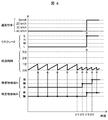
- FIG. 4 is a diagram (No. 1) for explaining an operation example by the vehicle control system according to the first embodiment.
- FIG. 4 in the vehicle control system 1 when the vehicle 10 is traveling in the direction of the section X1 on the track 100 when the monitoring operation of the ground sensor 30 and the vehicle-mounted sensor 102 is functioning normally, Whether the speed command, the risk rate, the elapsed time, and the detection result are shown is shown along with the passage of time.
- speed commands (0 km / h, 20 km / h, 30 km / h, 40 km / h) indicate speed commands input from the speed command calculation unit 108 to the vehicle control device 104.
- the value corresponds to the speed command value illustrated in FIG.
- the risk rate (S, H, M, L) of FIG. 4 has shown the risk rate input into the speed instruction
- the concrete value illustrated in FIG. Corresponds to the value of the risk rate.
- the elapsed time (3 minutes, 2 minutes, 1 minute, 0 minutes) in FIG. 4 indicates the elapsed time since the last monitoring operation was performed on the section X1, and the specific value is as follows.
- the obstacle detection A and the obstacle detection B of FIG. 4 have shown the monitoring result of the presence or absence of the obstacle with respect to the area X1 by the vehicle-mounted sensor 102 and the ground sensor 30, respectively.
- “Yes” means that an obstacle has been detected
- “No” means that no obstacle has been detected
- “Not” means that no obstacle has been detected yet.
- an arrow drawn from the points on the obstacle detection A and B with respect to the elapsed time performs a monitoring operation for detecting the presence or absence of an obstacle at the “point”, and the monitoring operation is performed. This indicates that the elapsed time is reset to “0 minutes”.
- FIG. 4 shows that each information amount (obstacle detection, elapsed time, risk rate, speed command) changes in conjunction with each other, and arrows are used to indicate the interlocking relationship. .
- processing time, transmission time, and the like occur. Therefore, the change in the information amount due to the interlocking does not occur at the same time, but the interlocking change is shown at the same time for convenience of explanation.
- the display method of FIG. 4 described above is the same as in FIGS. 5 and 7 described later, and redundant description is omitted hereinafter.
- the obstacle detection B by the ground sensor 30 periodically checks the presence or absence of an obstacle in the section X1 at intervals of 1 minute.
- the monitoring results by the obstacle detection B are all “none” until the time t11 is confirmed, and are “present” when the time t13 is confirmed.
- the presence / absence of the obstacle by the obstacle detection A by the in-vehicle sensor 102 is confirmed for the first time at time t12, and since the section X1 is not within the monitoring range of the in-vehicle sensor 102 until that time, "(Undecided).
- the monitoring result by the obstacle detection A is “none” at time t12, but “present” at time t14, which is the next confirmation timing.
- the operation of the vehicle control system 1 when such an obstacle detection monitoring result is obtained will be described in time series.
- the elapsed time is based on the monitoring result “No” by the obstacle detection B.
- the risk rate “L” having the lowest degree of danger is determined, so the target speed in the speed command is 40 km / h (pass), and the elapsed time
- the risk rate will not be upgraded because of the increase.
- a monitoring result by the obstacle detection A is also obtained at time t12. However, since the monitoring result at this time is also “none”, the risk rate and the target speed are not changed.
- the ground sensor 30 detects that there is an obstacle in the section X1
- the monitoring result “presence” by the obstacle detection B is obtained.
- the elapsed time is reset to 0 minutes because the monitoring result is obtained, while the risk rate “S” having the highest degree of danger is determined based on the monitoring result of the obstacle “present”, and the speed command
- the target speed at is 0 km / h (stop).
- the monitoring result of the obstacle “presence” is obtained even in the obstacle detection A by the in-vehicle sensor 102 at the timing of time t14 shortly after the time t13 when the monitoring result of the obstacle detection B is obtained.
- the vehicle control system 1 determines the risk rate with the higher degree of danger by the OR logical operation described above. It is possible to ensure safety by issuing a speed command to stop the vehicle 10 earlier based on the monitoring result of 30.
- FIG. 5 is a diagram (No. 2) for explaining an operation example by the vehicle control system according to the first embodiment.
- the vehicle 10 moves on the track 100 in the direction of the section X1.
- the speed control, the risk rate, the elapsed time, and the detection result displayed in the vehicle control system 1 when traveling are shown along with the passage of time.
- the in-vehicle sensor 102 can confirm the presence or absence of an obstacle in the section X1 for the first time at a later time t24, and the monitoring result by the obstacle detection A is obtained for the first time at the time t24.
- the vehicle 10 is controlled to stop.
- the time during which the presence or absence of an obstacle in the section X1 cannot be confirmed elapsed time
- the risk that the section X1 may have an obstacle increases.
- the vehicle 10 is decelerated or stopped proactively. By performing such vehicle control, the safety of the vehicle 10 can be ensured before actually entering the section X1.
- the vehicle 10 is stopped before reaching the section X1 by setting the target speed of the speed command to 0 km / h (stop) at time t23.
- the obstacle detection A by the sensor 102 obtains the monitoring result of the obstacle “none”
- the elapsed time is reset to 0 minutes and the risk rate “L” indicating the lowest degree of danger is determined. Since the risk rate “L” is determined, it is determined that a dangerous situation in which there may be an obstacle in the section X1 is avoided, so the target speed of the speed command is set to 40 km / h (pass). Returned, the vehicle 10 can pass through the section X1.
- the vehicle control system 1 controls the vehicle 10 to stop once based on the increase in the risk in the section X1
- the vehicle control system 1 subsequently enters the section X1 by the sensor. If it is confirmed that there is no obstacle, the control on the vehicle 10 can be canceled and returned to the normal traveling control without requiring on-site confirmation of the section X1 by an operator or the like.
- the fact that the vehicle control from the stop to the return of the vehicle 10 is possible without necessarily requiring confirmation by a worker or the like is particularly effective when the vehicle 10 is an unmanned driving vehicle. .
- the target speed of the speed command is set to 0 km / h (stop) at time t23 in FIG. 5, when the obstacle “A” monitoring result is obtained by the obstacle detection A at time t24, the vehicle The stop speed command for 10 is not released, and the vehicle 10 is stopped. Then, after the obstacle is removed by an operator, a driver or the like, the traveling of the vehicle 10 is resumed.
- the timing at which the vehicle-mounted sensor 102 performs the obstacle detection A monitoring operation is different from the timing at which the ground sensor 30 performs the obstacle detection B monitoring operation.
- the monitoring operation by the in-vehicle sensor 102 is set to “30 seconds”.
- the interval at which the monitoring operation is performed can be shortened by shifting the execution timing of the monitoring operation, the opportunity to reset the elapsed time increases, and the risk rate is unnecessary when no obstacle is detected in the section X1. It can also be expected to prevent the upgrade (that is, unnecessary speed limitation is not performed by the reduction of the target speed accompanying the upgrade of the risk rate). Such a shift in the timing of the monitoring operation can also be employed in second and third embodiments described later.
- the vehicle 10 traveling on the track 100 can pass safely by an obstacle that has entered a predetermined point (section X1) on the track. Is detected in the section X1 based on the information that the vehicle sensor 102 mounted on the vehicle 10 and the ground sensor 30 that can constantly monitor the section X1 monitor the presence or absence of an obstacle in the section X1.
- An obstacle that has entered the section X1 by determining the degree of danger of having an object (risk rate), determining the target speed of the speed command based on the determined risk rate, and controlling the traveling speed of the vehicle 10 Therefore, it is possible to suppress or prevent the safe passage of the vehicle 10 from being hindered.
- what target speed the vehicle 10 travels can be controlled to safely pass through the section X1 (or can it stop before reaching the section X1). Can be determined based on the elapsed time since the last monitoring of the presence or absence of obstacles in the section X1. Specifically, from the viewpoint that the longer the elapsed time, the higher the risk of being disturbed by newly entering obstacles, if there are obstacles in the section X1, manned driving while taking passenger safety into consideration Sometimes the driver (or automatic vehicle control system in the case of unmanned vehicles) controls the acceleration / deceleration of the vehicle by setting a lower target speed to make it easier to fully decelerate the vehicle before the obstacle. can do.
- the vehicle control system 1 when the control is simply performed to stop the vehicle 10 when the risk rate is high, the vehicle 10 can be operated when there is no obstacle at the predetermined point (section X1).
- the operation rate will decrease, by preparing multiple stages of risk rates corresponding to multiple stages of target speeds and determining one of them as the risk rate, the higher the risk rate, the higher the target speed.
- the risk rate is relatively low, the deceleration of the target speed can be weakened while the speed is set to low.
- the safety of the vehicle 10 and the operation rate of operation are reduced against the obstacle to the passage of the vehicle 10 due to an obstacle at a predetermined point. It is possible to realize vehicle control that is preventively handled while achieving both.
- FIG. 6 is a diagram for explaining a configuration example of a vehicle control system according to a second embodiment.
- the vehicle control system 2 according to the second embodiment includes not only the ground sensor 30 and the vehicle-mounted sensor 102 of the vehicle 10 but also the trajectory of the vehicle 10.
- the vehicle-mounted sensor 402 provided in the vehicle 40 traveling on a track 200 different from 100 also monitors whether there is an obstacle at a predetermined point (section X1).
- the configuration of the vehicle control system 2 is substantially the same as that of the vehicle control system 1 according to the first embodiment except that it is related to the vehicle 40, and the description thereof is omitted for the sake of brevity. To do.
- the vehicle 40 travels in a direction opposite to the vehicle 10 on the track 200, and approaches the section X ⁇ b> 1 from the opposite direction to the vehicle 10.
- the relationship between the track 200 and the track 100 can be regarded as a double track setting that is generally put into practical use in rail transport.
- the vehicle 40 includes a communication unit 401 that communicates with the outside, an in-vehicle sensor 402 that can detect the presence or absence of an obstacle within a predetermined range, and a position specifying unit 403 that can grasp the position of the vehicle 40.
- the section X1 is a specific example of a “predetermined point (predetermined range)” that is a target for detecting the presence or absence of an obstacle, and is considered to be the same as the section X1 in the first embodiment. good.
- the communication unit 401 can communicate data and signals with the outside of the vehicle 40 (in the case of FIG. 6, the communication unit 201 of the monitoring information server 20) by wireless communication, and is realized by a general wireless communication interface. can do.
- the in-vehicle sensor 402 is a sensor that can detect (or monitor) the presence or absence of an obstacle in a predetermined monitoring range, similar to the in-vehicle sensor 102 of the vehicle 10, and can use a general obstacle sensor. More specifically, the in-vehicle sensor 402 shown in FIG. 6 detects the presence or absence of an obstacle in the section X1 when the vehicle 40 traveling on the track 200 enters the section X1 on the track 100 in the monitoring range.
- the result of detection by the in-vehicle sensor 402 is transmitted to the monitoring information server 20 as a monitoring result.
- This monitoring result includes a detection result indicating the presence or absence of an obstacle and a monitoring time when the detection is performed.
- the timing at which the monitoring result is transmitted from the in-vehicle sensor 402 to the monitoring information server 20 may be any timing as long as the monitoring result of the section X1 can be reliably transmitted to the monitoring information server 20.
- the monitoring result may be periodically transmitted at a cycle shorter than the time required for the vehicle 40 to pass through the section X1, or the timing at which the vehicle 40 passes through the section X1. Then, the monitoring result may be transmitted. By transmitting the monitoring result at such timing, the monitoring result for the section X1 by the in-vehicle sensor 402 is reliably provided to the monitoring information server 20.
- the detection logic and detection mechanism of the in-vehicle sensor 402 are not limited to specific ones, and consider the environmental characteristics of the section X1 in the same manner as described above for each sensor of the vehicle control system 1 in the first embodiment. However, what is necessary is just to be suitable for detecting the presence or absence of an obstacle in the section X1 when the vehicle 40 approaches the section X1. In particular, in the case of the vehicle-mounted sensor 402, since the section X1 to be monitored is on a track 100 different from the track 200 on which the vehicle is traveling, it is preferable to have a long detection distance and a wide detection angle as monitoring performance. Therefore, specifically, for example, it is conceivable to use an optical sensor having a wide viewing angle.
- the position specifying unit 403 has a function of detecting the position of the vehicle 40. Specifically, for example, the position specifying unit 403 counts the number of rotations of a wheel, which is generally provided in a railway vehicle, and calculates a reference position (between stations and stations). A device for detecting the relative position of the vehicle 40 by calculating a relative position from the position of a beacon installed on the orbit), and a device for detecting the absolute position of the vehicle 40 using a satellite positioning system such as GPS. Can be realized. When the position specifying unit 403 grasps the position of the vehicle 40, the vehicle-mounted sensor 402 of the vehicle 40 can determine whether or not the section X1 is included in the monitoring range. The presence or absence can be confirmed.
- the monitoring information server 20 that receives the monitoring result of the vehicle-mounted sensor 402 of the vehicle 40, the monitoring result of the vehicle-mounted sensor 402 is stored and accumulated as monitoring information, similarly to the processing for the monitoring result of the ground sensor 30. More specifically, when the monitoring information management unit 202 stores / accumulates monitoring information in the monitoring information storage unit 203 and receives a monitoring information request from the vehicle 10 via the communication unit 201, the monitoring information storage unit The monitoring information stored in 203 is transmitted to the vehicle 10 via the communication unit 201.
- the process in the vehicle 10 is substantially the same as the process in the vehicle control system 1 of the first embodiment, detailed description is omitted.
- the monitoring information received from the monitoring information server 20 includes the monitoring result by the in-vehicle sensor 402, and therefore based on the monitoring results by the three sensors (the in-vehicle sensor 102, the ground sensor 30, and the in-vehicle sensor 402). Risk rate determination processing and target speed determination processing are performed.
- the monitoring results are obtained from more sensors than in the first embodiment, and the traveling control of the vehicle 10 is performed based on these monitoring results. Therefore, in addition to the effect obtained by the vehicle control system 1 of the first embodiment, it can be expected that the safety of the vehicle 10 and the operation operating rate are secured higher.
- FIG. 7 is a view for explaining an operation example by the vehicle control system according to the second embodiment.
- the obstacle detection A and the obstacle detection B shown in FIG. 7 are the monitoring result by the in-vehicle sensor 102 and the monitoring result by the ground sensor 30 as the obstacle detection A and the obstacle detection B shown in FIGS.
- the obstacle detection C newly shown in FIG. 7 is a monitoring result by the in-vehicle sensor 402.
- the obstacle detection B by the ground sensor 30 periodically outputs the monitoring result of the obstacle “none” for the section X1 at intervals of 1 minute until time t32, but at the timing of time t33, the obstacle sensor B outputs to the ground sensor 30.
- the monitoring results after the failure occurred are not output.
- the obstacle detection A by the in-vehicle sensor 102 is performed after the failure occurs in the in-vehicle sensor 102 at the time t31 without performing the monitoring operation for the section X1 (the monitoring result is “undecided” (undecided)).
- the monitoring result is no longer output.
- the section X1 is not within the monitoring range of the vehicle-mounted sensor 402 at the time t33 when both the obstacle detection A and the obstacle detection B monitoring results are not output. Therefore, the monitoring operation is performed on the section X1 within the monitoring range of the in-vehicle sensor 402 at the timing of time t34, and the monitoring result of the obstacle “none” is obtained. Is output.
- the vehicle-mounted sensor 102 fails at the time t31. Since the monitoring result of the obstacle detection A is “not yet” before that, in the case of FIG. 7, the monitoring result of the obstacle detection A is It does not affect the elapsed time or risk rate.
- the elapsed time is reset to 0 minutes every minute based on the monitoring result of the obstacle detection B by the ground sensor 30, so the risk rate is maintained at the lowest “L”,
- the target speed of the speed command is also maintained at 40 km / h (passing). This is the same as the situation from the start of FIG. 4 to time t11 and the situation from the start of FIG. 5 to time t21. Since the monitoring result is not output from the obstacle detection C, it becomes “not yet” and does not affect the risk rate or the like.
- the elapsed time is gradually increased since the monitoring result regarding the presence or absence of the obstacle is not output from any obstacle detection until time t34.
- the risk rate is upgraded to “M”
- the target speed of the speed command is reduced to 30 km / h (higher brake stop possible speed)
- an additional 1 minute has elapsed.
- the risk rate is upgraded to “H”
- the target speed of the speed command is reduced to 20 km / h (speed at which braking can be weakened).
- both of the sensors that can output the monitoring result have failed. Elapsed time increases without being obtained, but during this time, even if the presence or absence of an obstacle in the section X1 cannot be actually confirmed, there is an increased risk that an obstacle will exist as the elapsed time increases. Therefore, it is possible to upgrade the risk rate and decelerate the target speed of the speed command.
- the vehicle control system 2 by enabling the deceleration of the target speed, if it can be visually confirmed that there is an obstacle in the section X ⁇ b> 1, the passenger can only perform a weak brake braking. The vehicle 10 can be stopped in front of the section X1 while ensuring safety so as not to fall over.
- the risk rate “S” having the highest degree of danger is finally determined as described at time t23 in FIG.
- the target speed of the speed command is set to 0 km / h (stop), and the vehicle 10 is stopped.
- the vehicle 10 is an unmanned driving vehicle, it is necessary to restart the driving through a predetermined safety procedure after the worker has visited the section X1 of the target point and confirmed safety. Therefore, more time is required, and there is a possibility that the operation rate of operation of the vehicle 10 is significantly reduced.
- an obstacle detection C by the in-vehicle sensor 402 is prepared as an obstacle detection that can overcome such a situation. That is, even if both the in-vehicle sensor 102 and the ground sensor 30 break down, the vehicle 40 traveling from the opposite direction of the vehicle 10 approaches the section X1, and the in-vehicle sensor 402 confirms whether there is an obstacle in the section X1. By doing so, the increase in elapsed time can be reset, and the risk rate regarding the presence or absence of an obstacle in the section X1 can be recalculated.
- the obstacle detection C obtains a monitoring result of the obstacle “none”, so that the elapsed time is reset to 0 minutes, and the obstacle is also “no”. Therefore, the risk rate is downgraded to “L” with the lowest degree of danger.
- the target speed of the speed command is also restored to 40 km / h (passing), so that the traveling speed of the vehicle 10 can be restored without having to go through the safety procedure described above by a driver or a worker. Can pass the section X1.
- the risk rate is increased and the target speed of the speed command is reduced as the elapsed time increases.
- the traveling speed of the vehicle 10 can be controlled according to the degree of danger, and it is possible to deal with obstacles while ensuring the safety of passengers.
- the result of monitoring the presence or absence of an obstacle at the target point is also detected by a sensor (on-vehicle sensor 402) mounted on another vehicle 40.
- a sensor on-vehicle sensor 402 mounted on another vehicle 40.
- the target speed of the vehicle 10 is decelerated as the elapsed time increases, it is confirmed that there are no obstacles according to the newly obtained monitoring result. Since it is possible to return the vehicle 10 to normal driving without requiring on-site confirmation by a worker or the like, it is possible to perform driving control in consideration of safety of the vehicle 10 and to secure an operation rate of the vehicle 10. Can do.
- Such a vehicle control system 2 is more effective when the vehicle 10 is an unmanned driving vehicle.
- safety confirmation can only be relied on a sensor or the like.
- a sensor breaks down in the middle of a station and the presence or absence of an obstacle in the section X1 cannot be confirmed.
- safety can be confirmed because a vehicle traveling on a nearby track (for example, the vehicle 40 traveling on the track 200 in this example) can check whether there is an obstacle in the section X1.
- the vehicle 10 can be allowed to self-run in an unattended operation and arrive at the next station. In other words, it is possible to reduce and avoid the risk of time consumption and secondary damage due to the implementation of the recovery procedure of the worker, and it is possible to ensure both the safety and the operation rate of the vehicle 10 even in an unmanned driving vehicle. .
- the vehicle 40 travels in a direction opposite to the vehicle 10, but the travel direction of the vehicle 40 is not limited to this in the vehicle control system 2 according to the present embodiment.
- the present invention can also be applied to a case where the vehicle 40 travels in the same direction as the vehicle 10 on the track 200 adjacent to the track 100 of the vehicle 10, as is commonly seen on multiple railway lines.
- the vehicle 40 is the only vehicle on which the vehicle-mounted sensor is mounted in addition to the vehicle 10.
- each of a larger number of vehicles is similar to the vehicle-mounted sensor 402.
- These sensors may be provided. Specifically, for example, when two tracks are laid on both sides of the track 100, the vehicle sensor that is mounted on the vehicle traveling on each track is used to check whether there is an obstacle in the section X1. By making it possible to confirm, it is possible to collect more monitoring results in the monitoring information server 20 and to enable traveling control of the vehicle 10 with high reliability.
- FIG. 8 is a diagram for explaining a configuration example of a vehicle control system according to a third embodiment.
- the vehicle control system 3 according to the third embodiment includes a vehicle 50 that travels on the same track 100 prior to the vehicle 10, and a vehicle The vehicle tracking device 60 that can track 50 positions is further provided.
- the configuration of the vehicle control system 3 is substantially the same as that of the vehicle control system 1 according to the first embodiment except for the vehicle 50 and the vehicle tracking device 60, and description thereof is omitted for simplicity. To do.
- the vehicle control system 3 according to the third embodiment based on the traveling result of the vehicle 50 at the predetermined point (section X1), it is considered that the monitoring operation for the presence or absence of an obstacle at the predetermined point is performed. .
- the vehicle 50 travels on the same track 100 as the vehicle 10, and passes through the section X ⁇ b> 1 before the vehicle 10.
- the vehicle 50 includes a communication unit 501 that performs communication with the outside, and a position detection unit 502 that acquires position information of the vehicle 50.
- the communication unit 501 can communicate data and signals to the outside of the vehicle 50 (vehicle tracking device 60 in the case of FIG. 8) by wireless communication, and can be realized by a general wireless communication interface.
- the position detection unit 502 has a function of detecting the position of the vehicle 50, and periodically transmits position information obtained by the detection to the vehicle tracking device 60 via the communication unit 501. Although details are omitted, the position detection unit 502 can be realized by the same configuration as the position detection unit 105 described above in the first embodiment.
- the vehicle tracking device 60 is a device that can track the position of the vehicle 50 using the position information transmitted from the vehicle 50.
- the function of tracking the position of the vehicle 50 included in the vehicle tracking device 60 is a function generally used for the purpose of operation management in the railway transportation system, and is periodically transmitted from the position detection unit 502 of the vehicle 50.
- the position can be grasped based on the position information.
- the installation location of the vehicle tracking device 60 is not particularly limited.
- the vehicle tracking device 60 may be installed in a vehicle control room, or may be provided inside the monitoring information server 20.
- the vehicle tracking device 60 keeps track of the position of the vehicle 50 so as to grasp the time when the vehicle 50 passes through the section X1, and the operation of monitoring the presence or absence of an obstacle in the section X1 is performed based on the traveling result of the section X1 by the vehicle 50.
- the monitoring result of the monitoring operation (the monitoring result of the section X1 by the vehicle 50) is transmitted to the monitoring information server 20. Specifically, when the vehicle 50 passes through the section X1 safely, it means that there is no obstacle in the section X1 at the time of passage (monitoring time). The monitoring result “No” is transmitted. On the other hand, when the vehicle 50 cannot pass through the section X1 safely, a monitoring result indicating that the obstacle is “present” at the monitoring time is transmitted using the time when the vehicle 50 has reached the section X1 as the monitoring time.
- the monitoring information management unit 202 uses the vehicle 50 sent from the vehicle tracking device 60 in the same manner as the processing for the monitoring result of the section X1 by the ground sensor 30 sent from the ground sensor 30.
- the monitoring result of the section X1 is stored and accumulated in the monitoring information storage unit 203 as monitoring information.
- the monitoring information server 20 stores and accumulates the monitoring results of the section X1 by the ground sensor 30 and the monitoring results of the section X1 by the vehicle 50 as monitoring information. Monitoring information is transmitted to the vehicle 10. In the vehicle 10, the same processing as that described in the first embodiment is performed using the monitoring information and the monitoring result by the in-vehicle sensor 102. As a result, the speed determining unit 103 can determine the target speed of the speed command based on the monitoring results of the section X1 by the in-vehicle sensor 102, the ground sensor 30, and the vehicle 50, and the vehicle control device 104 can determine the determined target. The traveling speed of the vehicle 10 is controlled by the speed.
- the vehicle control system 3 when the vehicle 50 preceding the vehicle 10 on the same track 100 can safely pass through a predetermined point (section X1), Based on the idea that the passage record means that there is no obstacle in the section X1, it is treated as a monitoring result equivalent to the confirmation of the obstacle in the section X1 by the sensor. Therefore, the vehicle control system 3 collects more monitoring results than the vehicle control system 1 of the first embodiment by the amount of such monitoring results (monitoring results by the vehicle 50). In addition to the effects obtained by the vehicle control system 1 of the embodiment, it can be expected to control the operation of the vehicle 10 while ensuring more safety.
- the vehicle control system 3 according to the present embodiment is a monitoring result of the section X1 from the vehicle 40 traveling on another track 200 in the vehicle control system 2 according to the second embodiment. It can also be said that the monitoring result of the section X1 can be obtained by the passing result of the preceding vehicle 50 instead of the above. Therefore, according to the vehicle control system 3 according to the present embodiment, the same effect as that of the vehicle control system 2 according to the second embodiment can be obtained.
- a failure occurs in both the in-vehicle sensor 102 and the ground sensor 30 of the vehicle 10 so that an obstacle detection monitoring result cannot be obtained.
- the vehicle control system 3 obtains the monitoring result of the section X1 based on the passing result from the preceding vehicle 50, the elapsed time, the risk rate, Since the target speed of the speed command can be determined, the operation control of the vehicle 10 can be performed in consideration of the danger that there is an obstacle in the section X1.
- the vehicle tracking device 60 and the position detection unit 502 having functions generally used for the purpose of operation management or the like in the railway transportation system are provided. Since it can be used, monitoring of the presence or absence of an obstacle at a predetermined point without installing a new sensor in a vehicle other than the vehicle 10 to be subjected to vehicle control like the vehicle-mounted sensor 402 of the second embodiment. The result can be obtained.
- the vehicle control system 3 can make the safe passage result by the preceding vehicle 50 available as the monitoring result of the section X1, but when the actual rail transportation is assumed, the vehicle control system 3 takes precedence. Since a certain length is required for the operation interval between the vehicle 50 and the following vehicle 10, if the target speed of the vehicle 10 is determined based only on the monitoring result by the vehicle 50, Time may increase too much. If the elapsed time increases too much, a significant upgrade of the risk rate cannot be avoided, and as a result, there is a high possibility that the traveling speed (target speed) of the vehicle 10 will be significantly suppressed.
- the increase in elapsed time generally in rail transport, it is required to maintain a distance between vehicles of a predetermined level or more between the vehicle 10 and the vehicle 50 traveling on the same track 100 from the viewpoint of security. Therefore, an operation interval corresponding to at least the distance between the vehicles is generated, and the elapsed time is expected to increase due to the operation interval.
- the operation interval between the preceding vehicle 50 and the succeeding vehicle 10 is generally several minutes to several tens of minutes in the original transportation plan, the elapsed time is also several minutes to several tens of minutes. It is expected that
- a moving model such as a lightweight model vehicle (e.g., equivalent to a vehicle called "dew train" at a railroad transport site) or a small unmanned reconnaissance aircraft (e.g., a drone) flying along the track 100 may be used. .
- the vehicle control system 3 extended in this way, a vehicle left behind due to a landslide or a railroad crossing when a moving body that is a substitute for the vehicle 50 passes through the section X1 or above. Since the presence or absence of an obstacle such as can be confirmed, the monitoring result for the section X1 can be obtained. Specifically, for example, when a model vehicle or a small unmanned reconnaissance aircraft cannot pass through the section X1, the vehicle tracking device 60 recognizes that the position of the moving body stops moving from the periphery of the section X1. In such a case, the vehicle tracking device 60 can output the monitoring result for the section X1 by the mobile body by transmitting the result that there is an obstacle in the section X1 and the monitoring time thereof to the monitoring information server 20.
- the vehicle control system 3 can perform the same function as the vehicle 50 by substituting the vehicle 50 with the above moving body, and without worrying about the distance between vehicles required for security. For example, since the front near the vehicle 10 can be preceded, the problem of increase in elapsed time as described above when actual railway transportation is assumed can be solved.
- the monitoring target point for checking the presence or absence of an obstacle is limited to one section X1.
- the present invention is not limited to this, and for example, a plurality of sections to be monitored may be provided.
- the monitoring information server 20 stores and accumulates, as monitoring information, the result of confirming the presence or absence of an obstacle for each section to be monitored and its monitoring time. Then, if the monitoring information request unit 106 of the speed determination unit 103 requests the monitoring information server 20 for the monitoring information of the section that the vehicle 10 is about to reach by the monitoring information request, the section in each of the above-described embodiments.
- the same thing as that applied to X1 can be applied to each of the plurality of sections, and the speed control of the vehicle 10 can be realized based on the degree of danger of the presence or absence of obstacles in the plurality of sections.
- the present invention may be used even if a situation in which some of the monitoring results for the section to be monitored cannot be obtained due to a sensor failure or the like.
- the plurality of ground sensors 30 since it is possible to assist the determination of the degree of risk (risk rate) based on the other monitoring results obtained and to realize speed control sufficiently considering the safety of the vehicle 10, as described above, the plurality of ground sensors 30 In a situation where some of them may fail, it is expected that the number of scenes where the effects of the present invention are exhibited will increase.
- the speed determining unit 103 has been described as being mounted on the vehicle 10 (see FIGS. 1, 6, and 8).
- the invention is not limited to this.
- the invention may be arranged in a predetermined facility on the ground like the monitoring information server 20.
- the monitoring result by the vehicle-mounted sensor 102 of the vehicle 10 was demonstrated to be directly input into the speed determination part 103 (refer FIG. 2), this invention is not limited to this,
- the monitoring result by the vehicle-mounted sensor 102 is also monitoring information. It may be transmitted to the server 20 and stored / accumulated in the monitoring information storage unit 203. In such a case, since all the monitoring results are collected in the monitoring information server 20, it is also effective to perform the risk rate determination processing and the target speed determination processing in the monitoring information server 20.
- the present invention is not limited to a transportation system.
- an automobile or a vehicle may be used as long as the vehicle travels on a predetermined route and the vehicle is concerned about the contact with an obstacle that has entered the route.
- the present invention can also be applied to a transportation system using transport equipment in a factory.
- the present invention is not limited to the above-described embodiment, and includes various modifications.
- the above-described embodiment has been described in detail for easy understanding of the present invention, and is not necessarily limited to one having all the configurations described.
- a part of the configuration of an embodiment can be replaced with the configuration of another embodiment, and the configuration of another embodiment can be added to the configuration of an embodiment.
- each of the above-described configurations, functions, processing units, processing means, and the like may be realized by hardware by designing a part or all of them with, for example, an integrated circuit.
- Each of the above-described configurations, functions, and the like may be realized by software by interpreting and executing a program that realizes each function by the processor.
- Information such as programs, tables, and files for realizing each function can be stored in a recording device such as a memory, a hard disk, an SSD (Solid State Drive), or a recording medium such as an IC card, an SD card, or a DVD.
- control lines and information lines indicate what is considered necessary for explanation, and not all control lines and information lines on the product are necessarily shown. In practice, it may be considered that almost all the components are connected to each other.
- Vehicle control system 10 1, 2, 3 Vehicle control system 10, 40, 50 Vehicle 60 Vehicle tracking device 20 Monitoring information server 30 Ground sensor 100, 200 Track 101, 401, 501 Communication unit 102, 402 In-vehicle sensor 103 Speed determination unit 104 Vehicle control device 105 Position detection unit 106 Monitoring information request unit 107 Risk evaluation unit 108 Speed command calculation unit 111 Monitoring information calculation process 112 First risk rate calculation process 113 Second risk rate calculation process 114 Risk rate determination process 201 Communication unit 202 Monitoring information management Unit 203 monitoring information storage unit 403 position specifying unit 502 position detecting unit
Landscapes
- Engineering & Computer Science (AREA)
- Mechanical Engineering (AREA)
- Power Engineering (AREA)
- Transportation (AREA)
- Train Traffic Observation, Control, And Security (AREA)
- Electric Propulsion And Braking For Vehicles (AREA)
- Traffic Control Systems (AREA)
Abstract
La présente invention concerne un système de commande de véhicule (1) comprenant : un capteur embarqué (102) qui exécute une opération de surveillance pour détecter la présence d'un obstacle au niveau d'un point prescrit (section X1) d'une voie (100) et qui est installé dans un véhicule (10) se déplaçant sur la voie (100) ; un capteur de sol (30) qui exécute une opération de surveillance pour détecter la présence d'un obstacle au niveau du point prescrit (section X1) et qui est installé dans un emplacement prescrit autre que sur le véhicule (10) ; un serveur d'informations de surveillance (20) qui collecte et stocke le résultat de l'opération de surveillance exécutée par le capteur de sol (30) ; une unité de détermination de vitesse (103) qui détermine la vitesse cible du véhicule (10) sur la base des résultats de surveillance des capteurs ; et un dispositif de commande de véhicule (104) qui commande la vitesse de déplacement du véhicule (10) sur la base de la vitesse cible déterminée par l'unité de détermination de vitesse (103).
Priority Applications (2)
| Application Number | Priority Date | Filing Date | Title |
|---|---|---|---|
| EP17806355.8A EP3466793B1 (fr) | 2016-06-02 | 2017-05-15 | Système de commande de véhicule |
| CN201780031718.9A CN109153393B (zh) | 2016-06-02 | 2017-05-15 | 车辆控制系统 |
Applications Claiming Priority (2)
| Application Number | Priority Date | Filing Date | Title |
|---|---|---|---|
| JP2016-111061 | 2016-06-02 | ||
| JP2016111061A JP6633458B2 (ja) | 2016-06-02 | 2016-06-02 | 車両制御システム |
Publications (1)
| Publication Number | Publication Date |
|---|---|
| WO2017208797A1 true WO2017208797A1 (fr) | 2017-12-07 |
Family
ID=60477414
Family Applications (1)
| Application Number | Title | Priority Date | Filing Date |
|---|---|---|---|
| PCT/JP2017/018234 Ceased WO2017208797A1 (fr) | 2016-06-02 | 2017-05-15 | Système de commande de véhicule |
Country Status (4)
| Country | Link |
|---|---|
| EP (1) | EP3466793B1 (fr) |
| JP (1) | JP6633458B2 (fr) |
| CN (1) | CN109153393B (fr) |
| WO (1) | WO2017208797A1 (fr) |
Cited By (3)
| Publication number | Priority date | Publication date | Assignee | Title |
|---|---|---|---|---|
| CN110891160A (zh) * | 2018-09-10 | 2020-03-17 | 松下电器(美国)知识产权公司 | 影像传输装置、影像传输方法、以及记录介质 |
| TWI760261B (zh) * | 2021-07-14 | 2022-04-01 | 交通部臺灣鐵路管理局 | 列車速度監控系統 |
| JP2023142172A (ja) * | 2022-03-24 | 2023-10-05 | 株式会社日立製作所 | 運行計画割当装置、及び運行計画割当方法 |
Families Citing this family (7)
| Publication number | Priority date | Publication date | Assignee | Title |
|---|---|---|---|---|
| JP6843274B2 (ja) * | 2018-02-08 | 2021-03-17 | 三菱電機株式会社 | 障害物検出装置および障害物検出方法 |
| JP7269797B2 (ja) * | 2019-06-12 | 2023-05-09 | 株式会社日立製作所 | 列車制御システム及びコンピュータプログラム |
| EP3756971A1 (fr) * | 2019-06-24 | 2020-12-30 | Mitsubishi Electric R & D Centre Europe B.V. | Procédé de transmission de données d'amélioration de détection d'obstacles vers un transport de déplacement |
| CN112256052B (zh) * | 2020-09-14 | 2024-03-12 | 北京三快在线科技有限公司 | 无人机的速度控制方法、装置、无人机和存储介质 |
| CN112061179A (zh) * | 2020-09-17 | 2020-12-11 | 中车株洲电力机车有限公司 | 一种基于无人机的轨道车辆主动防碰撞装置及方法 |
| JP7406477B2 (ja) * | 2020-10-13 | 2023-12-27 | 株式会社日立製作所 | 障害物検知システム及び障害物検知方法 |
| JP7696094B2 (ja) * | 2021-07-02 | 2025-06-20 | パナソニックIpマネジメント株式会社 | 路線環境監視システムおよび路線環境監視方法 |
Citations (3)
| Publication number | Priority date | Publication date | Assignee | Title |
|---|---|---|---|---|
| JP2009202635A (ja) | 2008-02-26 | 2009-09-10 | Mitsubishi Electric Corp | 列車自動通報システム |
| JP2016043903A (ja) * | 2014-08-27 | 2016-04-04 | 株式会社日立製作所 | 障害物回避システム |
| JP2016046998A (ja) | 2014-08-27 | 2016-04-04 | 株式会社日立製作所 | 車両制御システム及び車両制御装置 |
Family Cites Families (5)
| Publication number | Priority date | Publication date | Assignee | Title |
|---|---|---|---|---|
| DE102006051241A1 (de) * | 2006-10-31 | 2008-05-08 | Engelmann, Frank | Sicherheitseinrichtung für den Transrapid und andere schienengeführte Fahrzeuge |
| CN203158028U (zh) * | 2013-04-11 | 2013-08-28 | 铁路科技(香港)有限公司 | 一种基于障碍物检测链的列车运行安全控制装置 |
| CN105636853B (zh) * | 2013-07-31 | 2018-04-24 | 铁路视像有限公司 | 用于障碍物识别和避开的系统和方法 |
| AU2015217536B2 (en) * | 2014-02-17 | 2019-05-30 | Ge Global Sourcing Llc | Video system and method for data communication |
| CN104331910B (zh) * | 2014-11-24 | 2017-06-16 | 沈阳建筑大学 | 一种基于机器视觉的轨道障碍物检测系统 |
-
2016
- 2016-06-02 JP JP2016111061A patent/JP6633458B2/ja active Active
-
2017
- 2017-05-15 WO PCT/JP2017/018234 patent/WO2017208797A1/fr not_active Ceased
- 2017-05-15 EP EP17806355.8A patent/EP3466793B1/fr active Active
- 2017-05-15 CN CN201780031718.9A patent/CN109153393B/zh active Active
Patent Citations (3)
| Publication number | Priority date | Publication date | Assignee | Title |
|---|---|---|---|---|
| JP2009202635A (ja) | 2008-02-26 | 2009-09-10 | Mitsubishi Electric Corp | 列車自動通報システム |
| JP2016043903A (ja) * | 2014-08-27 | 2016-04-04 | 株式会社日立製作所 | 障害物回避システム |
| JP2016046998A (ja) | 2014-08-27 | 2016-04-04 | 株式会社日立製作所 | 車両制御システム及び車両制御装置 |
Non-Patent Citations (1)
| Title |
|---|
| See also references of EP3466793A4 |
Cited By (4)
| Publication number | Priority date | Publication date | Assignee | Title |
|---|---|---|---|---|
| CN110891160A (zh) * | 2018-09-10 | 2020-03-17 | 松下电器(美国)知识产权公司 | 影像传输装置、影像传输方法、以及记录介质 |
| TWI760261B (zh) * | 2021-07-14 | 2022-04-01 | 交通部臺灣鐵路管理局 | 列車速度監控系統 |
| JP2023142172A (ja) * | 2022-03-24 | 2023-10-05 | 株式会社日立製作所 | 運行計画割当装置、及び運行計画割当方法 |
| JP7696854B2 (ja) | 2022-03-24 | 2025-06-23 | 株式会社日立製作所 | 運行計画割当装置、及び運行計画割当方法 |
Also Published As
| Publication number | Publication date |
|---|---|
| JP2017214041A (ja) | 2017-12-07 |
| CN109153393A (zh) | 2019-01-04 |
| EP3466793A4 (fr) | 2020-02-19 |
| JP6633458B2 (ja) | 2020-01-22 |
| EP3466793A1 (fr) | 2019-04-10 |
| CN109153393B (zh) | 2021-02-26 |
| EP3466793B1 (fr) | 2023-08-09 |
Similar Documents
| Publication | Publication Date | Title |
|---|---|---|
| JP6633458B2 (ja) | 車両制御システム | |
| US11724708B2 (en) | Fail-safe handling system for autonomous driving vehicle | |
| CN113619576B (zh) | 车辆控制方法、装置、设备、存储介质及自动驾驶车辆 | |
| CN110758484B (zh) | 列车自动驾驶方法、vobc、tias、区域控制器 | |
| KR102524297B1 (ko) | 차량용 자율 주행 장치 및 그의 자율 주행 방법과 그를 포함하는 차량 | |
| CN102616257B (zh) | 分布式列车控制 | |
| EP3577528B1 (fr) | Permettre le contrôle à distance d'un véhicule | |
| CN112622930A (zh) | 无人车的行驶控制方法、装置、设备以及自动驾驶车辆 | |
| JP5619632B2 (ja) | 移動体制御システム | |
| CA3103898C (fr) | Systeme de detection d`obstacle | |
| AU2017202545B2 (en) | Method for initializing the FS mode for the movement of a train on a railway equipped with an ERTMS/ETCS signaling system | |
| CN104969135A (zh) | 轨道交通网络中的车辆控制系统 | |
| JP2022065804A (ja) | 自律走行制御システム | |
| KR102669329B1 (ko) | 자동차용 운전자 보조 시스템을 위한 주변환경 모델링 장치 | |
| US12344291B2 (en) | System and method for monitoring failure of trains inside tunnels | |
| KR20260045736A (ko) | 차량 및 자율 주행 시스템 | |
| KR20160071645A (ko) | 열차의 분리-결합 시스템 | |
| CN112441086B (zh) | 轨道车辆及其控制方法、系统和列车控制与管理系统 | |
| JP7735243B2 (ja) | 自動運転総合制御装置 | |
| US12386369B2 (en) | System, control device, and control method for remote control of the vehicle | |
| JP7696854B2 (ja) | 運行計画割当装置、及び運行計画割当方法 | |
| JP7771997B2 (ja) | 遠隔運転システム、遠隔運転端末、及び遠隔運転のための方法 | |
| JP7482049B2 (ja) | 制御システム、車載装置、および管制装置 | |
| US20250346258A1 (en) | System and method for independent safety control | |
| US20230391384A1 (en) | Automated operation of railroad trains |
Legal Events
| Date | Code | Title | Description |
|---|---|---|---|
| 121 | Ep: the epo has been informed by wipo that ep was designated in this application |
Ref document number: 17806355 Country of ref document: EP Kind code of ref document: A1 |
|
| NENP | Non-entry into the national phase |
Ref country code: DE |
|
| ENP | Entry into the national phase |
Ref document number: 2017806355 Country of ref document: EP Effective date: 20190102 |