WO2017208881A1 - Stratifié de résine, dispositif d'affichage et polariseur - Google Patents
Stratifié de résine, dispositif d'affichage et polariseur Download PDFInfo
- Publication number
- WO2017208881A1 WO2017208881A1 PCT/JP2017/019004 JP2017019004W WO2017208881A1 WO 2017208881 A1 WO2017208881 A1 WO 2017208881A1 JP 2017019004 W JP2017019004 W JP 2017019004W WO 2017208881 A1 WO2017208881 A1 WO 2017208881A1
- Authority
- WO
- WIPO (PCT)
- Prior art keywords
- resin
- thermoplastic resin
- resin laminate
- meth
- mass
- Prior art date
- Legal status (The legal status is an assumption and is not a legal conclusion. Google has not performed a legal analysis and makes no representation as to the accuracy of the status listed.)
- Ceased
Links
Images

Classifications
-
- B—PERFORMING OPERATIONS; TRANSPORTING
- B32—LAYERED PRODUCTS
- B32B—LAYERED PRODUCTS, i.e. PRODUCTS BUILT-UP OF STRATA OF FLAT OR NON-FLAT, e.g. CELLULAR OR HONEYCOMB, FORM
- B32B27/00—Layered products comprising a layer of synthetic resin
- B32B27/30—Layered products comprising a layer of synthetic resin comprising vinyl (co)polymers; comprising acrylic (co)polymers
-
- B—PERFORMING OPERATIONS; TRANSPORTING
- B32—LAYERED PRODUCTS
- B32B—LAYERED PRODUCTS, i.e. PRODUCTS BUILT-UP OF STRATA OF FLAT OR NON-FLAT, e.g. CELLULAR OR HONEYCOMB, FORM
- B32B27/00—Layered products comprising a layer of synthetic resin
- B32B27/06—Layered products comprising a layer of synthetic resin as the main or only constituent of a layer, which is next to another layer of the same or of a different material
- B32B27/08—Layered products comprising a layer of synthetic resin as the main or only constituent of a layer, which is next to another layer of the same or of a different material of synthetic resin
-
- B—PERFORMING OPERATIONS; TRANSPORTING
- B32—LAYERED PRODUCTS
- B32B—LAYERED PRODUCTS, i.e. PRODUCTS BUILT-UP OF STRATA OF FLAT OR NON-FLAT, e.g. CELLULAR OR HONEYCOMB, FORM
- B32B27/00—Layered products comprising a layer of synthetic resin
- B32B27/18—Layered products comprising a layer of synthetic resin characterised by the use of special additives
-
- B—PERFORMING OPERATIONS; TRANSPORTING
- B32—LAYERED PRODUCTS
- B32B—LAYERED PRODUCTS, i.e. PRODUCTS BUILT-UP OF STRATA OF FLAT OR NON-FLAT, e.g. CELLULAR OR HONEYCOMB, FORM
- B32B27/00—Layered products comprising a layer of synthetic resin
- B32B27/30—Layered products comprising a layer of synthetic resin comprising vinyl (co)polymers; comprising acrylic (co)polymers
- B32B27/304—Layered products comprising a layer of synthetic resin comprising vinyl (co)polymers; comprising acrylic (co)polymers comprising vinyl halide (co)polymers, e.g. PVC, PVDC, PVF, PVDF
-
- B—PERFORMING OPERATIONS; TRANSPORTING
- B32—LAYERED PRODUCTS
- B32B—LAYERED PRODUCTS, i.e. PRODUCTS BUILT-UP OF STRATA OF FLAT OR NON-FLAT, e.g. CELLULAR OR HONEYCOMB, FORM
- B32B27/00—Layered products comprising a layer of synthetic resin
- B32B27/30—Layered products comprising a layer of synthetic resin comprising vinyl (co)polymers; comprising acrylic (co)polymers
- B32B27/308—Layered products comprising a layer of synthetic resin comprising vinyl (co)polymers; comprising acrylic (co)polymers comprising acrylic (co)polymers
-
- B—PERFORMING OPERATIONS; TRANSPORTING
- B32—LAYERED PRODUCTS
- B32B—LAYERED PRODUCTS, i.e. PRODUCTS BUILT-UP OF STRATA OF FLAT OR NON-FLAT, e.g. CELLULAR OR HONEYCOMB, FORM
- B32B27/00—Layered products comprising a layer of synthetic resin
- B32B27/36—Layered products comprising a layer of synthetic resin comprising polyesters
- B32B27/365—Layered products comprising a layer of synthetic resin comprising polyesters comprising polycarbonates
-
- B—PERFORMING OPERATIONS; TRANSPORTING
- B32—LAYERED PRODUCTS
- B32B—LAYERED PRODUCTS, i.e. PRODUCTS BUILT-UP OF STRATA OF FLAT OR NON-FLAT, e.g. CELLULAR OR HONEYCOMB, FORM
- B32B7/00—Layered products characterised by the relation between layers; Layered products characterised by the relative orientation of features between layers, or by the relative values of a measurable parameter between layers, i.e. products comprising layers having different physical, chemical or physicochemical properties; Layered products characterised by the interconnection of layers
- B32B7/02—Physical, chemical or physicochemical properties
- B32B7/022—Mechanical properties
-
- G—PHYSICS
- G02—OPTICS
- G02B—OPTICAL ELEMENTS, SYSTEMS OR APPARATUS
- G02B5/00—Optical elements other than lenses
- G02B5/30—Polarising elements
-
- G—PHYSICS
- G02—OPTICS
- G02F—OPTICAL DEVICES OR ARRANGEMENTS FOR THE CONTROL OF LIGHT BY MODIFICATION OF THE OPTICAL PROPERTIES OF THE MEDIA OF THE ELEMENTS INVOLVED THEREIN; NON-LINEAR OPTICS; FREQUENCY-CHANGING OF LIGHT; OPTICAL LOGIC ELEMENTS; OPTICAL ANALOGUE/DIGITAL CONVERTERS
- G02F1/00—Devices or arrangements for the control of the intensity, colour, phase, polarisation or direction of light arriving from an independent light source, e.g. switching, gating or modulating; Non-linear optics
- G02F1/01—Devices or arrangements for the control of the intensity, colour, phase, polarisation or direction of light arriving from an independent light source, e.g. switching, gating or modulating; Non-linear optics for the control of the intensity, phase, polarisation or colour
- G02F1/13—Devices or arrangements for the control of the intensity, colour, phase, polarisation or direction of light arriving from an independent light source, e.g. switching, gating or modulating; Non-linear optics for the control of the intensity, phase, polarisation or colour based on liquid crystals, e.g. single liquid crystal display cells
- G02F1/133—Constructional arrangements; Operation of liquid crystal cells; Circuit arrangements
- G02F1/1333—Constructional arrangements; Manufacturing methods
-
- B—PERFORMING OPERATIONS; TRANSPORTING
- B32—LAYERED PRODUCTS
- B32B—LAYERED PRODUCTS, i.e. PRODUCTS BUILT-UP OF STRATA OF FLAT OR NON-FLAT, e.g. CELLULAR OR HONEYCOMB, FORM
- B32B2307/00—Properties of the layers or laminate
- B32B2307/40—Properties of the layers or laminate having particular optical properties
- B32B2307/42—Polarizing, birefringent, filtering
-
- B—PERFORMING OPERATIONS; TRANSPORTING
- B32—LAYERED PRODUCTS
- B32B—LAYERED PRODUCTS, i.e. PRODUCTS BUILT-UP OF STRATA OF FLAT OR NON-FLAT, e.g. CELLULAR OR HONEYCOMB, FORM
- B32B2307/00—Properties of the layers or laminate
- B32B2307/70—Other properties
- B32B2307/732—Dimensional properties
-
- B—PERFORMING OPERATIONS; TRANSPORTING
- B32—LAYERED PRODUCTS
- B32B—LAYERED PRODUCTS, i.e. PRODUCTS BUILT-UP OF STRATA OF FLAT OR NON-FLAT, e.g. CELLULAR OR HONEYCOMB, FORM
- B32B2457/00—Electrical equipment
- B32B2457/20—Displays, e.g. liquid crystal displays, plasma displays
Definitions
- the present invention relates to, for example, a resin laminate suitably used in a display device, a display device including the resin laminate, and a polarizing plate with a resin laminate in which the resin laminate and a polarizing plate are laminated.
- Patent Document 1 discloses a transparent sheet containing a methacrylic resin and a vinylidene fluoride resin as a plastic sheet that is a substitute for a glass sheet.
- Display devices are used in various environments due to their high versatility.
- a display device including a plastic sheet is used in a harsh environment such as high temperature and high humidity, warping may occur as the resin expands and contracts.
- warping has become a bigger problem.
- An object of this invention is to provide the resin laminated body which is used suitably in a display apparatus and is hard to produce the curvature.
- the present inventors have studied in detail about a resin laminate suitably used in a display device, and have completed the present invention.
- the intermediate layer (A) contains 10 to 90% by mass of (meth) acrylic resin and 90 to 10% by mass of vinylidene fluoride resin based on the total resin contained in the intermediate layer (A).
- the weight average molecular weight (Mw) of the (meth) acrylic resin is 100,000 to 300,000,
- ⁇ C
- the intermediate layer (A) contains 35 to 45% by mass of (meth) acrylic resin and 65 to 55% by mass of vinylidene fluoride resin based on the total resin contained in the intermediate layer (A).
- R 1 represents a hydrogen atom or a methyl group
- R 2 represents an alkyl group having 1 to 8 carbon atoms when R 1 is a hydrogen atom
- R 2 represents an alkyl group having 2 to 2 carbon atoms when R 1 is a methyl group.
- thermoplastic resin layers (B) and (C) are a (meth) acrylic resin layer or a polycarbonate resin layer.
- thermoplastic resin layers (B) and (C) are polycarbonate resin layers, and contain 0.005 to 2.0% by mass of an ultraviolet absorber based on the total resin contained in each thermoplastic resin layer.
- thermoplastic resin layers (B) and (C) each contain 50% by mass or more (meth) acrylic resin based on the total resin contained in each thermoplastic resin layer.
- the resin laminated body in any one of.
- a display device comprising the resin laminate according to any one of [1] to [12].
- a display device comprising the polarizing plate with a resin laminate according to [14].
- the resin laminate of the present invention is less likely to warp even when used in an environment such as high temperature and high humidity, and is preferably used in a display device or the like.
- the resin laminate of the present invention has at least an intermediate layer (A) and thermoplastic resin layers (B) and (C) present on both sides of the intermediate layer (A).
- the resin laminate of the present invention has at least a configuration in which the thermoplastic resin layer (B) / intermediate layer (A) / thermoplastic resin layer (C) are laminated in this order.
- the intermediate layer (A) contains 10 to 90% by mass of (meth) acrylic resin and 90 to 10% by mass of vinylidene fluoride resin based on the total resin contained in the intermediate layer (A).
- the amount of (meth) acrylic resin is lower than the above lower limit, sufficient transparency cannot be obtained, and when the amount of (meth) acrylic resin is higher than the above upper limit, sufficient dielectric constant cannot be obtained.
- the amount of the vinylidene fluoride resin is lower than the above lower limit, a sufficient dielectric constant cannot be obtained, and when the amount of the vinylidene fluoride resin is higher than the above upper limit, durability and sufficient transparency cannot be obtained.
- the intermediate layer (A) has a (meth) acrylic resin of 30 to 60% by mass based on the total resin contained in the intermediate layer (A) from the viewpoint of easily increasing the dielectric constant and enhancing the transparency of the resin laminate. And 70 to 40% by mass of vinylidene fluoride resin, more preferably 35 to 45% by mass of (meth) acrylic resin and 65 to 55% by mass of vinylidene fluoride resin, more preferably 37 to 45% by mass. % Of (meth) acrylic resin and 63 to 55% by mass of vinylidene fluoride resin are more preferable, and 38 to 45% by mass of (meth) acrylic resin and 62 to 55% by mass of vinylidene fluoride resin are included. It is particularly preferable to include 38 to 43% by mass of (meth) acrylic resin and 62 to 57% by mass of vinylidene fluoride resin.
- Examples of the (meth) acrylic resin contained in the intermediate layer (A) of the resin laminate of the present invention include, for example, homopolymers of (meth) acrylic monomers such as (meth) acrylic acid esters and (meth) acrylonitrile, 2 types
- the copolymer of the above (meth) acryl monomer, the copolymer of monomers other than (meth) acryl monomer and (meth) acryl monomer, etc. are mentioned.
- the term “(meth) acryl” means “acryl” or “methacryl”.
- the (meth) acrylic resin is preferably a methacrylic resin from the viewpoint of easily increasing the hardness, weather resistance and transparency of the resin laminate.
- a methacrylic resin is a polymer of a monomer mainly composed of a methacrylic acid ester (also referred to as alkyl methacrylate).
- a homopolymer of a methacrylic acid ester also referred to as polyalkyl methacrylate
- two or more kinds of methacrylic acid examples thereof include a copolymer of an ester and a copolymer of 50% by mass or more of a methacrylic acid ester and a monomer other than 50% by mass of a methacrylic acid ester.
- copolymer of a methacrylic acid ester and a monomer other than the methacrylic acid ester from the viewpoint of easily improving optical properties and weather resistance, 70% by mass or more of the methacrylic acid ester and 30% with respect to the total amount of the monomers. Copolymers with other monomers of less than or equal to mass% are preferred, and copolymers of more than 90 mass% of methacrylic acid esters with other monomers of less than or equal to 10 mass% are more preferred.
- Examples of monomers other than methacrylic acid esters include acrylic acid esters and monofunctional monomers having one polymerizable carbon-carbon double bond in the molecule.
- monofunctional monomers examples include styrene monomers such as styrene, ⁇ -methylstyrene and vinyltoluene; alkenyl cyanides such as acrylonitrile and methacrylonitrile; acrylic acid; methacrylic acid; maleic anhydride; N-substituted Maleimide; and the like.
- the (meth) acrylic resin may be copolymerized with N-substituted maleimides such as phenylmaleimide, cyclohexylmaleimide and methylmaleimide, or in the molecular chain (in the main skeleton or in the polymer).
- N-substituted maleimides such as phenylmaleimide, cyclohexylmaleimide and methylmaleimide
- a lactone ring structure, a glutaric anhydride structure, a glutarimide structure, or the like may be introduced into the main chain).
- the (meth) acrylic resin is specifically, 50 to 99.9% by mass, preferably 70.0 to 99.8% by mass, based on (a1) methyl methacrylate homopolymer and / or (a2) all structural units constituting the copolymer
- each structural unit can be calculated by analyzing the obtained polymer by pyrolysis gas chromatography and measuring the peak area corresponding to each monomer.
- R 1 represents a hydrogen atom or a methyl group
- R 2 represents an alkyl group having 1 to 8 carbon atoms when R 1 is a hydrogen atom
- R 2 represents an alkyl group having 2 to 2 carbon atoms when R 1 is a methyl group. Represents an alkyl group of 8;
- R 1 represents a hydrogen atom or a methyl group
- R 2 represents an alkyl group having 1 to 8 carbon atoms
- R 2 represents the number of carbon atoms
- the alkyl group having 2 to 8 carbon atoms include ethyl group, propyl group, isopropyl group, butyl group, sec-butyl group, tert-butyl group, pentyl group, hexyl group, heptyl group, octyl group and the like.
- R 2 is preferably an alkyl group having 2 to 4 carbon atoms from the viewpoint of heat resistance, and more preferably an ethyl group.
- the weight average molecular weight of the (meth) acrylic resin contained in the intermediate layer (A) (hereinafter sometimes referred to as Mw) is 100,000 to 300,000. When Mw is lower than the above lower limit, transparency when exposed to a high temperature and high humidity environment is not sufficient, and when Mw is higher than the above upper limit, film formability when producing a resin laminate cannot be obtained. .
- the Mw of the (meth) acrylic resin is preferably 120,000 or more, and more preferably 150,000 or more, from the viewpoint of easily increasing transparency when exposed to a high temperature and high humidity environment.
- the Mw of the (meth) acrylic resin is preferably 250,000 or less, and more preferably 200,000 or less, from the viewpoint of film formability when producing a resin laminate.
- the weight average molecular weight is measured by gel permeation chromatography (GPC) measurement.
- the (meth) acrylic resin is usually 0.1 to 20 g / 10 min, preferably 0.2 to 5 g / 10 min, more preferably 0.5 to 3 g as measured under the condition of 3.8 kg load and 230 ° C. / 10 minutes melt mass flow rate (hereinafter sometimes referred to as MFR).
- MFR melt mass flow rate
- the MFR is preferably not more than the above upper limit because it is easy to increase the strength of the obtained film, and is preferably not less than the above lower limit from the viewpoint of film formability of the resin laminate.
- the MFR can be measured in accordance with a method defined in JIS K 7210: 1999 “Plastics—Test Methods for Melt Mass Flow Rate (MFR) and Melt Volume Flow Rate (MVR) of Thermoplastic Plastics”. This JIS stipulates that poly (methyl methacrylate) -based materials are measured under conditions of a temperature of 230 ° C. and a load of 3.80 kg (37.3 N).
- the (meth) acrylic resin preferably has a Vicat softening temperature (hereinafter sometimes referred to as VST) of preferably 90 ° C. or higher, more preferably 100 ° C. or higher, and even more preferably 102 ° C. or higher.
- VST Vicat softening temperature
- the upper limit of VST is not specifically limited, Usually, it is 150 degrees C or less.
- VST can be measured by the B50 method described in accordance with JIS K 7206: 1999. VST can be adjusted to the above range by adjusting the type of monomer and its ratio.
- (Meth) acrylic resin can be prepared by polymerizing the above monomers by a known method such as suspension polymerization or bulk polymerization.
- MFR, Mw, VST, etc. can be adjusted to a preferable range by adding a suitable chain transfer agent.
- the chain transfer agent an appropriate commercial product can be used. What is necessary is just to determine the addition amount of a chain transfer agent suitably according to the kind of monomer, its ratio, the characteristic to obtain
- Examples of the vinylidene fluoride resin contained in the intermediate layer (A) of the resin laminate of the present invention include vinylidene fluoride homopolymers and copolymers of vinylidene fluoride and other monomers.
- the vinylidene fluoride resin is selected from the group consisting of trifluoroethylene, tetrafluoroethylene, hexafluoropropylene, chlorotrifluoroethylene, perfluoroalkyl vinyl ether and ethylene from the viewpoint of easily increasing the transparency of the obtained resin laminate.
- It is preferably a copolymer of at least one monomer and vinylidene fluoride and / or a homopolymer of polyvinylidene fluoride (polyvinylidene fluoride), more preferably polyvinylidene fluoride.
- the weight average molecular weight (Mw) of the vinylidene fluoride resin contained in the intermediate layer (A) is preferably 100,000 to 500,000, more preferably 150,000 to 450,000, still more preferably 200,000 to 450,000, particularly preferably 350,000 to 450,000. It is easy for the transparency of the resin laminate to be increased when the resin laminate of the present invention is exposed to a high-temperature and high-humidity environment (for example, 60 ° C. and relative humidity 90%) that Mw is equal to or more than the above lower limit. preferable. Moreover, it is preferable that Mw is not more than the above upper limit because the film-forming property of the resin laminate is easily improved.
- the weight average molecular weight is measured by gel permeation chromatography (GPC) measurement.
- the vinylidene fluoride resin is preferably 0.1 to 40 g / 10 min, more preferably 0.1 to 30 g / 10 min, even more preferably 0.1, as measured under the condition of 3.8 kg load and 230 ° C. It has a melt mass flow rate (MFR) of ⁇ 25 g / 10 min.
- MFR melt mass flow rate
- the MFR is more preferably 0.2 g / 10 min or more, and even more preferably 0.5 g / 10 min or more.
- the MFR is more preferably 20 g / 10 min or less, even more preferably 5 g / 10 min or less, and particularly preferably 2 g / 10 min or less.
- MFR is not more than the above upper limit because it is easy to suppress a decrease in transparency when the resin laminate is used for a long period of time. It is preferable that the MFR is not less than the above lower limit because the film formability of the resin laminate can be easily improved.
- the MFR can be measured in accordance with a method defined in JIS K 7210: 1999 “Plastics—Test Methods for Melt Mass Flow Rate (MFR) and Melt Volume Flow Rate (MVR) of Thermoplastic Plastics”.
- the vinylidene fluoride resin is industrially produced by a suspension polymerization method or an emulsion polymerization method.
- the suspension polymerization method is carried out by using water as a medium, dispersing the monomer as droplets in the medium with a dispersant, and polymerizing an organic peroxide dissolved in the monomer as a polymerization initiator, A granular polymer of 100 to 300 ⁇ m is obtained.
- Suspension polymers are preferred because they have a simpler manufacturing process than powdered emulsions, have excellent powder handling properties, and do not contain an emulsifier or salting-out agent containing an alkali metal unlike emulsion polymers.
- a commercially available vinylidene fluoride resin may be used.
- examples of preferable commercially available products include “KF Polymer (registered trademark) T # 1300, T # 1100, T # 1000, T # 850, W # 850, W # 1000, W # 1100 and W # 1300 from Kureha Corporation.
- the intermediate layer (A) may further contain another resin different from the (meth) acrylic resin and the vinylidene fluoride resin.
- the amount of other resins is preferably 15% by mass or less, preferably 10% by mass or less, based on the total resin contained in the intermediate layer (A). Is more preferable, and it is still more preferable that it is 5 mass% or less.
- other resins include polycarbonate resin, polyamide resin, acrylonitrile-styrene copolymer, methyl methacrylate-styrene copolymer, and polyethylene terephthalate.
- the intermediate layer (A) may further contain another resin, but from the viewpoint of transparency, the amount of the other resin is preferably 1% by mass or less, and the resin contained in the intermediate layer (A) is ( More preferably, it is only a (meth) acrylic resin and a vinylidene fluoride resin.
- the content of alkali metal in the intermediate layer (A) is preferably 50 ppm or less, more preferably 30 ppm or less, even more preferably 10 ppm or less, particularly preferably 1 ppm or less, based on the total resin contained in the intermediate layer (A). It is. It is preferable that the content of alkali metal in the intermediate layer (A) is not more than the above upper limit because it is easy to suppress a decrease in transparency when the resin laminate is used for a long time in a high temperature and high humidity environment.
- the lower limit of the content of alkali metal in the intermediate layer (A) is 0, and it is extremely preferable that the content is not substantially contained from the viewpoint of easily suppressing the decrease in transparency of the resin laminate.
- the intermediate layer (A) contains, for example, 0.05 ppm or more of alkali metal such as sodium or potassium derived from the remaining emulsifier.
- alkali metal such as sodium or potassium derived from the remaining emulsifier.
- the amount of the emulsifier remaining in the resin increases, and the intermediate layer (A) The alkali metal content is also increased. From the viewpoint of easily suppressing a decrease in transparency of the resin laminate, it is preferable to use a resin having a low alkali metal content as the (meth) acrylic resin and vinylidene fluoride resin contained in the intermediate layer (A). .
- the amount of the compound containing the alkali metal is reduced during the polymerization of the resin, or the compound containing the alkali metal is increased by increasing the washing step after the polymerization. Remove it.
- the alkali metal content can be determined by, for example, inductively coupled plasma mass spectrometry (ICP / MS).
- ICP / MS inductively coupled plasma mass spectrometry
- examples of inductively coupled plasma mass spectrometry include sample pellets to be measured such as a high temperature ashing melting method, a high temperature ashing acid dissolution method, a Ca-added ashing acid dissolution method, a combustion absorption method, and a low temperature ashing acid dissolution method.
- the sample may be ashed by an appropriate method, dissolved in an acid, and the volume of the dissolved solution may be determined, and the content of alkali metal may be measured by inductively coupled plasma mass spectrometry.
- the resin laminate of the present invention has at least thermoplastic resin layers (B) and (C) present on both sides of the intermediate layer (A).
- the thermoplastic resin layer (B) and the thermoplastic resin layer (C) may be the same layer or different layers.
- the thermoplastic resin layers (B) and (C) contain at least one thermoplastic resin.
- the thermoplastic resin layers (B) and (C) are preferably 60% by mass or more, more preferably 70% by mass, based on the total resin contained in each thermoplastic resin layer, from the viewpoint of easily improving moldability. As described above, even more preferably, 80% by mass or more of the thermoplastic resin is included. The upper limit of the amount of the thermoplastic resin is 100% by mass.
- the thermoplastic resin include (meth) acrylic resin, polycarbonate resin, and cycloolefin resin.
- the thermoplastic resin is preferably a (meth) acrylic resin or a polycarbonate resin from the viewpoint of easily improving the adhesion between the thermoplastic resin layers (B) and (C) and the intermediate layer (A).
- the thermoplastic resin layers (B) and (C) may contain the same thermoplastic resin or may contain different thermoplastic resins.
- the thermoplastic resin layers (B) and (C) preferably contain the same thermoplastic resin from the viewpoint of easily suppressing
- the thermoplastic resin contained in the thermoplastic resin layers (B) and (C) is preferably 100 to 160 ° C., as measured in accordance with JIS K 7206: 1999, from the viewpoint of heat resistance of the resin laminate. Preferably it has a Vicat softening temperature of 102-155 ° C, even more preferably 102-152 ° C.
- the Vicat softening temperature is the Vicat softening temperature of the resin when the thermoplastic resin layer contains one kind of thermoplastic resin, and the thermoplastic resin layer contains two or more kinds of thermoplastic resins. Is the Vicat softening temperature of a mixture of a plurality of thermoplastic resins.
- thermoplastic resin layers (B) and (C) are provided with other resins (for example, thermosetting resins such as fillers and resin particles) other than the thermoplastic resin for the purpose of increasing the strength and elasticity of the thermoplastic resin layer. May be included.
- the amount of the other resin is preferably 40% by mass or less, more preferably 30% by mass or less, and even more preferably 20% by mass or less, based on the total resin contained in each thermoplastic resin layer. .
- the lower limit of the amount of other resins is 0% by mass.
- thermoplastic resin layers (B) and (C) satisfy the following relationship.
- ⁇ L
- ⁇ L is preferably 17 ⁇ m or less, and more preferably 15 ⁇ m or less, from the viewpoint of easily suppressing warpage of the resin laminate of the present invention.
- ⁇ L means the difference between the average values of the film thicknesses of the thermoplastic resin layers (B) and (C), and ⁇ L is adjusted by adjusting the film thicknesses of the thermoplastic resin layers (B) and (C). Can be within range.
- the film thickness of the thermoplastic resin layer is measured using a microscope (for example, a microscope manufactured by Micro Square Inc.). Let the average value of the value obtained by performing the said measurement in arbitrary 10 points
- thermoplastic resin layers (B) and (C) further satisfy the following relationship.
- ⁇ BC
- ⁇ B and ⁇ C are respectively represented by the following formulas, and in the following formula, ⁇ ′ B and ⁇ ′ C are for the thermoplastic resin layers (B) and (C) in the resin laminate, respectively.
- Measured birefringence (I) and ⁇ B and ⁇ C are resin laminates after annealing for 4 hours at a temperature 25 ° C. lower than the Vicat softening temperature of the thermoplastic resin layers (B) and (C), respectively.
- ⁇ B
- ⁇ C
- the birefringence (I) measured for the thermoplastic resin layers (B) and (C) in the resin laminate is the thermoplastic resin layer (B) in the resin laminate or
- the phase difference (R) at a wavelength of 590 nm of (C) is measured using an automatic birefringence meter (for example, “KOBRA-CCD” manufactured by Oji Scientific Co., Ltd.), and is calculated from the obtained phase difference by the following equation.
- Birefringence ( ⁇ ). ⁇ R / L [In the formula, ⁇ represents birefringence, R represents a phase difference at a wavelength of 590 nm, and L represents the length (nm) of the short side of the sample for phase difference measurement. ]
- the birefringence (II) measured for (C) is an automatic birefringence meter using the resin laminate after the annealing treatment to determine the phase difference (R) at a wavelength of 590 nm of the thermoplastic resin layer (B) or (C).
- the birefringence ( ⁇ ) calculated by the following equation from the obtained phase difference.
- the annealing treatment is a treatment in which the resin laminate is left at a temperature 25 ° C. lower than the Vicat softening temperature of the thermoplastic resin layers (B) and (C) for 4 hours, and the thermoplastic resin layers (B) and ( When the Vicat softening temperatures of C) are different from each other, annealing is performed at a temperature 25 ° C. lower than the higher Vicat softening temperature.
- ⁇ R / L [In the formula, ⁇ represents birefringence, R represents a phase difference at a wavelength of 590 nm, and L represents the length (nm) of the short side of the sample for phase difference measurement. ]
- thermoplastic resin layers (B) and (C) are (meth) acrylic resin layers
- ⁇ B and ⁇ C are each from the viewpoint of easily suppressing warpage of the resin laminate of the present invention. It is preferably 0.16 ⁇ 10 ⁇ 4 or less, and more preferably 0.15 ⁇ 10 ⁇ 4 or less.
- thermoplastic resin layers (B) and (C) are polycarbonate resin layers
- ⁇ B and ⁇ C are each 0.61 ⁇ 10 ⁇ 4 or less from the same viewpoint. Is preferably 0.60 ⁇ 10 ⁇ 4 or less.
- ⁇ B and ⁇ C are respectively obtained by applying the birefringence (I) of the thermoplastic resin layers (B) and (C) in the resin laminate and the annealing treatment to the resin laminate (B).
- (C) means the difference between the birefringence (II) of the thermoplastic resin layers (B) and (C) measured after removing the intrinsic birefringence generated during molding. A large difference indicates that the distortion of the polymer polymer array generated when molding each layer is large.
- ⁇ B and ⁇ C can be set within the above range by adjusting the cooling rate during the production of the resin laminate. Since ⁇ B and ⁇ C are absolute values, their lower limit values are zero.
- ⁇ BC is preferably 0.18 ⁇ 10 ⁇ 4 or less from the viewpoint of easily suppressing the warpage of the resin laminate of the present invention.
- ⁇ BC is obtained by subtracting the difference between birefringence (II) and birefringence (I) in the thermoplastic resin layer (C) from the difference between birefringence (II) and birefringence (I) in the thermoplastic resin layer (B).
- the absolute value which is large, indicates that the difference in the degree of distortion generated during the molding process is large between the thermoplastic resin layer (B) and the thermoplastic resin layer (C).
- ⁇ BC can be set within the above range by adjusting the type and amount of the resin contained in the thermoplastic resin layers (B) and (C) and the cooling rate. Since ⁇ BC is an absolute value, its lower limit is zero.
- the resin laminate has the thermoplastic resin layers (B) and (C) in which the distortion of the polymer arrangement is within a specific range, and the resin laminate of the present invention is used under conditions such as high temperature and high humidity. It is thought that this is one reason that warpage is unlikely to occur.
- thermoplastic resin layers (B) and (C) further satisfy the following relationship.
- ⁇ T
- ⁇ T is preferably 3 ° C. or less, more preferably 2 ° C. or less, even more preferably 1 ° C. or less, and even more preferably 0 ° C. from the viewpoint of easily suppressing warpage of the resin laminate of the present invention. It is very preferable that ⁇ T means a difference in Vicat softening temperature between the thermoplastic resin layers (B) and (C), and a large difference indicates a large difference in strain relaxation rate. ⁇ T can be set within the above range by adjusting the type and composition of the resin contained in the thermoplastic resin layers (B) and (C).
- the Vicat softening temperature of the thermoplastic resin layer is measured in accordance with the B50 method defined in JIS K 7206: 1999 “Plastics—Thermoplastic—Vicat Softening Temperature (VST) Test Method”.
- the Vicat softening temperature can be measured using a heat distortion tester (for example, “148-6 continuous type” manufactured by Yasuda Seiki Seisakusho Co., Ltd.).
- the measurement may be performed using a test piece obtained by press-molding each raw material to a thickness of 3 mm. Since ⁇ T is an absolute value, its lower limit is 0.
- thermoplastic resin layers (B) and (C) are preferably a (meth) acrylic resin layer or a polycarbonate resin layer from the viewpoint of good molding processability and easy enhancement of adhesion to the intermediate layer (A). .
- thermoplastic resin layers (B) and (C) are (meth) acrylic resin layers
- the thermoplastic resin layers (B) and (C) contain one or more (meth) acrylic resins.
- the thermoplastic resin layers (B) and (C) are preferably 50% by mass or more based on the total resin contained in each thermoplastic resin layer, more preferably 60% by mass or more, and even more, from the viewpoint of surface hardness. Preferably 70 mass% or more of (meth) acrylic resin is included.
- Examples of the (meth) acrylic resin include the resins described for the (meth) acrylic resin contained in the intermediate layer (A). Unless it mentions specially, the preferable (meth) acrylic resin described about the intermediate
- the (meth) acrylic resin contained in the thermoplastic resin layers (B) and (C) and the (meth) acrylic resin contained in the intermediate layer (A) may be the same or different.
- the weight average molecular weight (Mw) of the (meth) acrylic resin is preferably 50,000 to 300,000, more preferably 70,000 to 250, from the viewpoint of good moldability and easy increase in mechanical strength. 1,000.
- the weight average molecular weight is measured by gel permeation chromatography (GPC) measurement.
- the thermoplastic resin layers (B) and (C) may further contain a thermoplastic resin other than one or more (meth) acrylic resins.
- a thermoplastic resin compatible with the (meth) acrylic resin is preferable.
- methyl methacrylate-styrene-maleic anhydride copolymer for example, “Resphi” manufactured by Denki Kagaku Kogyo
- methyl methacrylate-methacrylic acid copolymer for example, “Altglass HT121” manufactured by Arkema
- polycarbonate resin Is mentioned.
- the thermoplastic resin other than the (meth) acrylic resin is preferably 115 ° C.
- thermoplastic resin layer (B) and (C) does not contain a vinylidene fluoride resin substantially from a viewpoint of heat resistance and surface hardness.
- the pencil hardness of the thermoplastic resin layers (B) and (C) is preferably HB or more, more preferably F or more, and more preferably H or more, from the viewpoint of enhancing scratch resistance. Is even more preferred.
- thermoplastic resin layers (B) and (C) are polycarbonate resin layers
- the thermoplastic resin layers (B) and (C) contain one or more polycarbonate resins.
- the thermoplastic resin layers (B) and (C) are preferably 60% by mass or more, more preferably 70% by mass or more based on the total resin contained in each thermoplastic resin layer, from the viewpoint of impact resistance. More preferably, 80% by mass or more of polycarbonate resin is included.
- polycarbonate resin examples include polymers obtained by a phosgene method in which various dihydroxydiaryl compounds and phosgene are reacted, or a transesterification method in which a dihydroxydiaryl compound and a carbonic ester such as diphenyl carbonate are reacted.
- a polycarbonate resin produced from 2,2-bis (4-hydroxyphenyl) propane (commonly called bisphenol A) can be mentioned.
- dihydroxydiaryl compound examples include bisphenol 4-, bis (4-hydroxyphenyl) methane, 1,1-bis (4-hydroxyphenyl) ethane, 2,2-bis (4-hydroxyphenyl) butane, 2, 2-bis (4-hydroxyphenyl) octane, bis (4-hydroxyphenyl) phenylmethane, 2,2-bis (4-hydroxyphenyl-3-methylphenyl) propane, 1,1-bis (4-hydroxy-3) -Tert-butylphenyl) propane, 2,2-bis (4-hydroxy-3-bromophenyl) propane, 2,2-bis (4-hydroxy-3,5-dibromophenyl) propane, 2,2-bis ( Bis (hydroxyaryl) alkanes such as 4-hydroxy-3,5-dichlorophenyl) propane, 1,1 Bis (hydroxyaryl) cycloalkanes such as bis (4-hydroxyphenyl) cyclopentane, 1,1-bis (4-hydroxyphenyl) cyclohexane, 4,4
- Trihydric or higher phenols include phloroglucin, 4,6-dimethyl-2,4,6-tri- (4-hydroxyphenyl) -heptene, 2,4,6-dimethyl-2,4,6-tri- (4 -Hydroxyphenyl) -heptane, 1,3,5-tri- (4-hydroxyphenyl) -benzol, 1,1,1-tri- (4-hydroxyphenyl) -ethane and 2,2-bis- [4 4- (4,4'-dihydroxydiphenyl) -cyclohexyl] -propane and the like.
- Polycarbonate resins other than the above polycarbonate resins include polycarbonates synthesized from isosorbite and aromatic diols.
- An example of the polycarbonate is “DURABIO (registered trademark)” manufactured by Mitsubishi Chemical Corporation.
- polycarbonate resin Commercially available products may be used as the polycarbonate resin.
- the weight average molecular weight (Mw) of the polycarbonate resin is preferably 20,000 to 70,000, more preferably 25,000 to 60,000, from the viewpoint of easily improving impact resistance and moldability. It is.
- the weight average molecular weight is measured by gel permeation chromatography (GPC) measurement.
- MVR melt volume rate
- MVR melt volume rate
- the thermoplastic resin layers (B) and (C) may further contain a thermoplastic resin other than one or more polycarbonate resins.
- a thermoplastic resin compatible with the polycarbonate resin is preferable, a (meth) acrylic resin is more preferable, and a methacrylic resin having an aromatic ring or a cycloolefin in the structure is still more preferable.
- the thermoplastic resin layers (B) and (C) contain a polycarbonate resin and the above (meth) acrylic resin, the surface hardness of the thermoplastic resin layers (B) and (C) includes only the polycarbonate resin. It is preferable because it can be made higher than that.
- At least one of the intermediate layer (A), the thermoplastic resin layer (B), and (C) in the resin laminate of the present invention is a variety of commonly used additives as long as the effects of the present invention are not impaired. May further be included.
- additives include stabilizers, antioxidants, ultraviolet absorbers, light stabilizers, foaming agents, lubricants, mold release agents, antistatic agents, flame retardants, mold release agents, polymerization inhibitors, and flame retardant aids.
- coloring agents such as reinforcing agents, nucleating agents, and bluing agents.
- Examples of the colorant include compounds having an anthraquinone skeleton, compounds having a phthalocyanine skeleton, and the like. Among these, a compound having an anthraquinone skeleton is preferable from the viewpoint of heat resistance.
- the content of the colorant in each layer is appropriately determined according to the purpose, the type of the colorant, and the like. You can choose.
- a bluing agent used as the colorant, the content thereof can be about 0.01 to 10 ppm based on the total resin contained in each layer containing the bluing agent. This content is preferably 0.01 ppm or more, more preferably 0.05 ppm or more, even more preferably 0.1 ppm or more, and preferably 7 ppm or less, more preferably 5 ppm or less, even more preferably 4 ppm or less, Especially preferably, it is 3 ppm or less.
- Known bluing agents can be used as appropriate.
- Macrolex (registered trademark) Blue RR manufactured by Bayer
- Macrolex (registered trademark) Blue 3R manufactured by Bayer
- Sumiplast registered trademark
- Viloet B manufactured by Sumika Chemtex Co., Ltd.
- Polycinslen registered trademark
- Blue RLS manufactured by Clariant
- Dialesin Violet D Dialesin Blue G
- Dialesin Blue N aboveve, manufactured by Mitsubishi Chemical Corporation
- the ultraviolet absorber is not particularly limited, and various conventionally known ultraviolet absorbers may be used.
- an ultraviolet absorber having an absorption maximum at 200 to 320 nm or 320 to 400 nm can be mentioned. Specific examples include triazine ultraviolet absorbers, benzophenone ultraviolet absorbers, benzotriazole ultraviolet absorbers, benzoate ultraviolet absorbers, and cyanoacrylate ultraviolet absorbers.
- an ultraviolet absorber you may use 1 type of these ultraviolet absorbers individually or in combination of 2 or more types.
- Use of at least one ultraviolet absorber having an absorption maximum at 200 to 320 nm and at least one ultraviolet absorber having an absorption maximum at 320 to 400 nm in combination can more effectively prevent damage from ultraviolet rays To preferred.
- UV absorber such as “Kemisorb 102” (2,4-bis (2,4-dimethylphenyl) -6- (2-hydroxy-4-N-octyl) manufactured by Chemipro Kasei Co., Ltd.
- Oxyphenyl) -1,3,5-triazine) (absorbance 0.1), “ADEKA STAB LA-F70” (2,4,6-tris (2-hydroxy-4-hexyloxy-3-methyl) manufactured by ADEKA Corporation Phenyl) -1,3,5-triazine) (absorbance 0.6), “Adekastab LA-31, LA-31RG, LA-31G” (2,2′-methylenebis (4- (1,1,3,3 -Tetramethylbutyl) -6- (2H-benzotriazol-2-yl) phenol) (absorbance 0.2), “ADEKA STAB LA-46” (2- (4,6) manufactured by ADEKA Corporation Diphenyl-1,3,5-triazin-2-yl) -5- (2- (2-ethylhexanoyloxy) ethoxy) phenol) (absorbance 0.05) or “TINUVIN 1577” manufactured by BASF Japan Ltd.
- the absorbance of the exemplified ultraviolet absorber is at 380 nm. This is absorbance, which can be measured using a spectrophotometer (for example, a spectrophotometer U-4100 manufactured by HITACHI) after dissolving an ultraviolet absorber in chloroform at a concentration of 10 mg / L.
- a spectrophotometer for example, a spectrophotometer U-4100 manufactured by HITACHI
- the content of the UV absorber in each layer depends on the purpose, the type of the UV absorber, etc. You may select suitably according to it.
- the content of the ultraviolet absorber can be about 0.005 to 2.0% by mass based on the total resin contained in each layer containing the ultraviolet absorber.
- the content of the ultraviolet absorber is preferably 0.01% by mass or more, more preferably 0.02% by mass or more, and even more preferably 0.03% by mass or more. Further, the content of the ultraviolet absorber is preferably 1.5% by mass or less, more preferably 1.0% by mass or less.
- the content of the ultraviolet absorber is not less than the above lower limit from the viewpoint of easily enhancing the ultraviolet absorption effect, and being not more than the above upper limit prevents a change in the color (for example, yellowness YI) of the resin laminate. It is preferable because it is easy to do. For example, it is preferable to use the above-mentioned commercially available “ADK STAB LA-31, LA-31RG, LA-31G” in the above amounts.
- thermoplastic resin layers (B) and (C) are polycarbonate resin layers, and 0.005 to 2.0 mass% based on the total resin contained in each thermoplastic resin layer. It is preferable to contain a UV absorber because it is easy to obtain a resin laminate having excellent light resistance.
- the average value of the film thickness of the resin laminate is 100 to 2000 ⁇ m, and the average value of the film thickness of the thermoplastic resin layers (B) and (C) is 10 to 200 ⁇ m, respectively. From the viewpoint of easily suppressing warpage of the resin laminate of the present invention.
- the average value of the film thickness of the resin laminate of the present invention is preferably 100 ⁇ m or more, more preferably 200 ⁇ m or more, and even more preferably 300 ⁇ m or more, from the viewpoint of the rigidity of the resin laminate. Moreover, from a viewpoint of transparency, Preferably it is 2000 micrometers or less, More preferably, it is 1500 micrometers or less, More preferably, it is 1000 micrometers or less.
- the film thickness of the resin laminate is measured with a digital micrometer. Let the average value which performed the said measurement in 10 points
- the average values of the film thicknesses of the thermoplastic resin layers (B) and (C) are each preferably 10 ⁇ m or more, more preferably 30 ⁇ m or more, and even more, from the viewpoint of easily increasing the surface hardness. Preferably it is 50 micrometers or more. From the viewpoint of dielectric constant, each is preferably 200 ⁇ m or less, more preferably 175 ⁇ m or less, and even more preferably 150 ⁇ m or less.
- the measuring method of the average value of the film thickness of the thermoplastic resin layer is as described above.
- the average value of the film thickness of the intermediate layer (A) is preferably 100 ⁇ m or more, more preferably 200 ⁇ m or more, and even more preferably 300 ⁇ m or more, from the viewpoint of dielectric constant. Moreover, from a viewpoint of transparency, Preferably it is 1500 micrometers or less, More preferably, it is 1200 micrometers or less, More preferably, it is 1000 micrometers or less.
- the average value of the film thickness of the intermediate layer (A) can be measured by the same method as the measurement of the average value of the film thickness of the thermoplastic resin layer.
- the resin laminate of the present invention is preferably a dielectric of 3.5 or more, more preferably 4.0 or more, and even more preferably 4.1 or more, from the viewpoint of obtaining a function sufficient for use in a display device such as a touch panel.
- the upper limit value of the dielectric constant is not particularly limited, but is usually 20.
- the dielectric constant can be adjusted by adjusting the kind and amount of the vinylidene fluoride resin contained in the intermediate layer (A) of the resin laminate of the present invention, or by adding a high dielectric constant compound such as ethylene carbonate or propylene carbonate. Can be adjusted within the range.
- the dielectric constant is in accordance with JIS K 6911: 1995, and the resin laminate of the present invention is allowed to stand for 24 hours in an environment with a relative humidity of 50% at 23 ° C., and in this environment, 3 V , Measured at 100 kHz.
- a commercially available instrument may be used, for example, “precision LCR meter HP4284A” manufactured by Agilent Technologies, Inc. may be used.
- the resin laminate of the present invention is preferably transparent when visually observed.
- the resin laminate of the present invention is preferably 85% or more, more preferably 88% or more, and even more preferably 90% or more of the total light transmittance as measured in accordance with JIS K7361-1: 1997. Has a rate (Tt).
- the upper limit of the total light transmittance is 100%. It is preferable that the resin laminate after exposure for 120 hours at 60 ° C. in an environment with a relative humidity of 90% still has a total light transmittance in the above range.
- the resin laminate of the present invention is measured in accordance with JIS K7136: 2000 using a resin laminate after 120 hours of exposure at 60 ° C. in an environment with a relative humidity of 90%, and preferably 2.0% or less. More preferably, the haze (haze value) is 1.8% or less, and even more preferably 1.5% or less.
- the resin laminate of the present invention is measured according to JIS Z 8722: 2009 using the resin laminate after exposure for 120 hours in an environment of 90% relative humidity at 60 ° C., preferably 1.5 or less. More preferably, it has a yellowness (Yellow Index: YI value) of 1.4 or less, and even more preferably 1.3 or less.
- the resin laminate of the present invention having the above-described haze and yellowness is not easily warped even when used in an environment such as high temperature and high humidity, and maintains transparency and easily suppresses yellowing. To preferred.
- the resin laminate of the present invention may further include at least one functional layer in addition to the intermediate layer (A), the thermoplastic resin layer (B), and (C).
- the functional layer is preferably present on the surface of the thermoplastic resin layer (B) and / or (C) opposite to the intermediate layer (A).
- Examples of the functional layer include a hard coat layer, an antireflection layer, an antiglare layer, an antistatic layer, and an anti-fingerprint layer.
- These functional layers may be laminated on the resin laminate of the present invention via an adhesive layer, or may be a coating layer laminated by coating.
- a cured film described in JP 2013-86273 A may be used as the functional layer.
- the functional layer is, for example, coated on one side or both sides of at least one functional layer selected from the group consisting of a hard coat layer, an antiglare layer, an antistatic layer, and an anti-fingerprint layer by a coating method, a sputtering method, a vacuum deposition method, etc.
- the antireflection layer may be a further coated layer, or may be a layer in which an antireflection sheet is bonded to one side or both sides of the at least one functional layer.
- the thickness of the functional layer may be appropriately selected according to the purpose of each functional layer, but is preferably 1 ⁇ m or more, more preferably 3 ⁇ m or more, and even more preferably 5 ⁇ m or more from the viewpoint of easily expressing the function. From the viewpoint of easily preventing cracking, the thickness is preferably 100 ⁇ m or less, more preferably 80 ⁇ m or less, and even more preferably 70 ⁇ m or less.
- the resin laminate of the present invention is produced from the resin composition (A) that gives the intermediate layer (A), and the resin compositions (B) and (C) that give the thermoplastic resin layers (B) and (C), respectively. Can do.
- the resin compositions (B) and (C) need only contain at least a resin that gives the thermoplastic resin layers (B) and (C).
- a composition containing more than one kind of component may be used, or a single type of resin may be used.
- Resin composition (A) is usually obtained by kneading (meth) acrylic resin and vinylidene fluoride resin.
- the kneading can be performed, for example, by a method including a step of melt kneading at a temperature of 150 to 350 ° C. at a shear rate of 10 to 1000 / sec.
- the temperature at the time of melt kneading is preferably 150 ° C. or higher because the resin can be sufficiently melted, and is preferably 350 ° C. or lower because it is easy to suppress thermal decomposition of the resin. Furthermore, it is preferable that the shear rate at the time of melt-kneading is 10 / second or more because the resin can be sufficiently kneaded, and it is preferably 1000 / second or less because the decomposition of the resin is easily suppressed.
- the melt-kneading is preferably performed at a temperature of 180 to 300 ° C., more preferably 200 to 300 ° C., preferably 20 to 700 / second, and more. Preferably, it is carried out at a shear rate of 30 to 500 / sec.
- an ordinary mixer or kneader can be used as an apparatus used for melt kneading.
- Specific examples include a single-screw kneader, a twin-screw kneader, another-screw extruder, a Henschel mixer, a Banbury mixer, a kneader, and a roll mill.
- a high shearing device or the like may be used.
- Resin compositions (B) and (C) can also be produced in the same manner as resin composition (A), for example, by melt kneading under the above temperature and shear rate. Further, for example, when the thermoplastic resin layers (B) and (C) contain one kind of thermoplastic resin, a resin laminate may be manufactured by performing melt extrusion described later without melt-kneading in advance.
- the additives may be included in advance in the resin contained in each layer, and are added when the resin is melt-kneaded. Alternatively, the resin may be added after melt-kneading, or may be added when a resin laminate is produced using the resin composition.
- the resin laminate of the present invention having at least the intermediate layer (A) and the thermoplastic resin layers (B) and (C) present on both sides of the intermediate layer (A) can be produced by, for example, melt extrusion molding, solution casting
- Each layer (A) to (C) is produced separately from the resin composition (A) to (C) by a film forming method, a hot press method, an injection molding method, etc., and these are applied via, for example, an adhesive or an adhesive.
- the resin compositions (A) to (C) may be laminated and integrated by melt coextrusion molding.
- the resin laminate of the present invention can be produced by melt coextrusion molding of the resin compositions (A) to (C), which is usually secondary molding as compared with the resin laminate produced by bonding. This is preferable because a resin laminate that can be easily processed is obtained.
- the resin composition (A) and the resin compositions (B) and (C) are separately fed into two or three uniaxial or biaxial extruders and melted respectively.
- the intermediate layer (A) formed from the resin composition (A) and the thermoplastic resin layers (B) and (C) are laminated and integrated through a feed block die, a multi-manifold die, and the like. This is a molding method.
- the resin compositions (B) and (C) are the same composition, one composition melt-kneaded in one extruder is divided into two via a feed block die and the thermoplastic resin layer (B) and (C) may be formed.
- the obtained resin laminate is preferably cooled and solidified by, for example, a roll unit.
- the resin laminate of the present invention is distributed in the form of a resin laminate having a size of, for example, a width of 500 to 3000 mm and a length of 500 to 3000 mm obtained by cutting out from the laminate produced as described above.
- a display device is a device having a display element and includes a light-emitting element or a light-emitting device as a light-emitting source.
- a liquid crystal display device an organic electroluminescence (EL) display device, an inorganic electroluminescence (EL) display device, a touch panel display device, an electron emission display device (for example, a field emission display device (FED), a surface field emission display device) (SED)), electronic paper (display device using electronic ink or electrophoretic element), plasma display device, projection display device (for example, a grating light valve (GLV) display device, a display having a digital micromirror device (DMD)) Apparatus) and a piezoelectric ceramic display.
- GLV grating light valve
- DMD digital micromirror device
- the liquid crystal display device includes any of a transmissive liquid crystal display device, a transflective liquid crystal display device, a reflective liquid crystal display device, a direct view liquid crystal display device, a projection liquid crystal display device, and the like. These display devices may be a display device that displays a two-dimensional image, or may be a stereoscopic display device that displays a three-dimensional image.
- the resin laminate of the present invention is suitably used in these display devices, for example, as a front plate or a transparent electrode.
- a transparent conductive film is produced by forming a transparent conductive film on at least one surface of the resin laminate of the present invention, and the transparent electrode is formed from the transparent conductive sheet. Can be manufactured.
- the transparent conductive film may be directly formed on the surface of the resin laminate of the present invention, or a transparent conductive film is previously formed.
- a plastic film may be laminated on the surface of the resin laminate of the present invention.
- the film base material of the plastic film on which the transparent conductive film is formed in advance is not particularly limited as long as it is a transparent film and can form a transparent conductive film.
- a transparent film for example, polyethylene terephthalate, polyethylene naphthalate , Polycarbonate, acrylic resin, polyamide, a mixture or laminate thereof.
- the film may be coated for the purpose of improving surface hardness, preventing Newton's ring, imparting antistatic properties, and the like.
- the method of laminating a film, on which a transparent conductive film has been formed in advance, on the surface of the resin laminate of the present invention may be any method as long as it is free from bubbles and can provide a uniform and transparent sheet.
- a method of laminating using an adhesive that is cured by normal temperature, heating, ultraviolet light, or visible light may be used, or a transparent adhesive tape may be used for bonding.
- a vacuum deposition method As a method for forming a transparent conductive film, a vacuum deposition method, a sputtering method, a CVD method, an ion plating method, a spray method, and the like are known, and these methods are appropriately used depending on a required film thickness. Can do.
- the sputtering method for example, a normal sputtering method using an oxide target, a reactive sputtering method using a metal target, or the like is used. At this time, oxygen, nitrogen, or the like may be introduced as a reactive gas, or means such as ozone addition, plasma irradiation, or ion assist may be used in combination. If necessary, a bias such as direct current, alternating current, and high frequency may be applied to the substrate.
- the transparent conductive metal oxide used for the transparent conductive film is indium oxide, tin oxide, zinc oxide, indium-tin composite oxide, tin-antimony composite oxide, zinc-aluminum composite oxide, indium-zinc composite. An oxide etc. are mentioned. Of these, indium-tin composite oxide (ITO) is preferable from the viewpoint of environmental stability and circuit processability.
- a coating agent containing various conductive polymers capable of forming a transparent conductive film is applied to the surface of the resin laminate of the present invention, and ionization such as heat or ultraviolet rays is performed. A method of curing the coating by irradiating with radiation can also be applied.
- the conductive polymer polythiophene, polyaniline, polypyrrole, and the like are known, and these conductive polymers can be used.
- the thickness of the transparent conductive film is not particularly limited, but when a transparent conductive metal oxide is used, it is usually 50 to 2000 mm, preferably 70 to 000 mm. If it is this range, it will be excellent in both electroconductivity and transparency.
- the thickness of the transparent conductive sheet is not particularly limited, and an optimum thickness can be selected according to the demand for the product specifications of the display.
- the touch sensor panel can be manufactured by using the resin laminate of the present invention as a display panel face plate and using the transparent conductive sheet manufactured from the resin laminate of the present invention as a transparent electrode such as a touch screen.
- the resin laminate of the present invention can be used as a touch screen window sheet, and the transparent conductive sheet can be used as an electrode substrate for a resistive film type or capacitive type touch screen.
- An external touch sensor panel having a touch screen function can be obtained by arranging the touch screen on the front surface of a liquid crystal display device, an organic EL display device or the like.
- the present invention also provides a display device including the resin laminate of the present invention.
- the display device of the present invention can be, for example, the display device described above.
- the present invention also provides a polarizing plate with a resin laminate in which the resin laminate of the present invention and a polarizing plate are laminated, and a display device including the polarizing plate with a resin laminate.
- the resin laminate of the present invention is laminated on the polarizing plate via an optical adhesive such as an adhesive and a pressure-sensitive adhesive.
- an optical adhesive such as an adhesive and a pressure-sensitive adhesive.
- the adhesive or pressure-sensitive adhesive a known one may be used as appropriate.
- FIG. 2 is a schematic cross-sectional view showing a preferred embodiment of a liquid crystal display device including the resin laminate of the present invention.
- the resin laminate 10 of the present invention is laminated on the polarizing plate 11 via the optical adhesive layer 12, and this laminate can be disposed on the viewing side of the liquid crystal cell 13.
- a polarizing plate 11 is usually disposed on the back side of the liquid crystal cell 13.
- the liquid crystal display device 14 is composed of such members.
- FIG. 2 is an example of a liquid crystal display device, and the display device of the present invention is not limited to this configuration.
- VST Vinyl softening Temperature
- MFR melt mass flow rate
- MVR melt volume flow rate
- the film thickness of the resin laminate was measured with a digital micrometer.
- the average value obtained by performing the above measurement at 10 points was defined as the average value of the film thickness of the resin laminate.
- the thickness of each layer of the intermediate layer (A), the thermoplastic resin layer (B) and (C) is measured after cutting the resin laminate perpendicularly to the surface direction and polishing the cross section with sandpaper It was measured by observing with a microscope manufactured by Micro Square.
- the average value obtained by performing the above measurement at 10 points was defined as the average value of the film thickness of each layer.
- the birefringence (birefringence I) of the thermoplastic resin layers (B) and (C) in the resin laminate The resin laminate was cut in a direction perpendicular to the laminate surface to obtain a rectangular parallelepiped having a size of a short side of 600 ⁇ m and a long side of 8 mm on the surface of the thermoplastic resin layer and having a thickness that is the film thickness of the resin laminate. This was fixed on the glass so that the cross section faced upward, and a sample for phase difference measurement was obtained. Fixing was performed using an epoxy adhesive.
- the obtained sample is set in an automatic birefringence meter (“KOBRA-CCD” manufactured by Oji Scientific Co., Ltd.) so that the layer to be measured is directed to the incident side of the measurement light, and the temperature is 23 ⁇ 2 ° C. and the humidity is 50 ⁇ 5%.
- the phase difference (R) at a wavelength of 590 nm was measured.
- Birefringence ( ⁇ ) was calculated from the following equation using the obtained phase difference.
- the birefringence calculated in this way is defined as birefringence (I).
- ⁇ R / L [In the formula, ⁇ represents birefringence, R represents a phase difference, and L represents the length (nm) of the short side of the sample for phase difference measurement. ]
- the birefringence birefringence of the thermoplastic resin layers (B) and (C) in the resin laminate after annealing for 4 hours at a temperature 25 ° C. lower than the Vicat softening temperature of the thermoplastic resin layers (B) and (C)) II)
- the resin laminate is left for 4 hours in an oven set at a temperature 25 ° C. lower than the Vicat softening temperature of the thermoplastic resin layers (B) and (C) and annealed.
- a resin laminate for birefringence (II) measurement from which distortion during molding was removed was obtained.
- birefringence (II) the phase difference was measured by the same method as the measurement of the birefringence (I), and the birefringence was calculated by substituting it into the above formula.
- the birefringence calculated in this way is defined as birefringence (II).
- annealing treatment was performed at a temperature 25 ° C. lower than the higher Vicat softening temperature.
- the prepared sheet-shaped resin laminate was cut into a size of 100 ⁇ 56 mm to prepare a sample for warpage evaluation.
- the sample was allowed to stand in a thermo-hygrostat with a temperature of 60 ° C. and a relative humidity of 90% for 120 hours, and the change in warpage was evaluated before and after that.
- the evaluation was performed by observing the four ends of the sample with a high-precision CCD micrometer manufactured by Keyence Co., Ltd., measuring the height of the generated warp, and calculating the average value of the height of the warp at the four ends.
- the obtained pellet-like methacrylic resin composition was analyzed by pyrolysis gas chromatography under the following conditions, and each peak area corresponding to methyl methacrylate and acrylate ester was measured.
- the structural unit derived from methyl methacrylate was 97.0% by mass
- the structural unit derived from methyl acrylate was 3.0% by mass.
- a standard product of a methacrylic resin having a weight ratio of acrylic ester units to methyl methacrylate units of W 0 (known) is pyrolyzed under the above pyrolysis conditions, and the generated decomposition product is subjected to the above gas chromatography analysis conditions.
- a pellet-like methacrylic resin (ii) was prepared in the same manner as in Production Example 1 except that 98.9 parts by weight of methyl methacrylate, 1.1 parts by weight of methyl acrylate, and 0.16 parts by weight of the chain transfer agent were changed. And the content of the structural unit was measured.
- the structural unit derived from methyl methacrylate was 97.5% by mass, and the structural unit derived from methyl acrylate was 2.5% by mass.
- Acrylic rubber particles having a spherical three-layer structure and an average particle diameter of 0.22 ⁇ m were produced according to Example 3 of JP-B-55-27576 and used as acrylic rubber particles (i).
- the acrylic rubber particles (i) are an innermost layer which is a hard polymer obtained by polymerization using methyl methacrylate and a small amount of allyl methacrylate, butyl acrylate as a main component, and further using styrene and a small amount of allyl methacrylate. It had an intermediate layer which was a polymerized elastic polymer, and an outermost layer which was a hard polymer polymerized using methyl methacrylate and a small amount of methyl acrylate.
- the average particle diameter of the acrylic rubber particles (i) is obtained by mixing the acrylic rubber particles with a methacrylic resin to form a film, and dyeing the elastic polymer (intermediate layer) with ruthenium oxide in the film cross section. The diameter of the stained part was measured and determined. 65 parts of methacrylic resin (i) pellets and 35 parts of the acrylic rubber particles (i) were mixed with a super mixer, and melt-kneaded with a twin screw extruder to obtain pellets.
- Table 1 shows the physical properties of the methacrylic resins (i) to (iii) obtained in Production Examples 1 to 3.
- the weight average molecular weight (Mw) of the vinylidene fluoride resin was measured by gel permeation chromatography (GPC). Using polystyrene as a standard reagent, a calibration curve was created from the elution time and molecular weight, and the weight average molecular weight of each resin was measured. Specifically, 40 mg of resin was dissolved in 20 ml of N-methylpyrrolidone (NMP) solvent to prepare a measurement sample. As a measuring device, two columns “TSKgel SuperHM-H”, which is a column manufactured by Tosoh Corporation, and one “SuperH2500” were arranged in series, and an RI detector was used as a detector.
- NMP N-methylpyrrolidone
- the weight average molecular weight of the polycarbonate resin was measured by GPC.
- a methacrylic resin manufactured by Showa Denko KK with a narrow molecular weight distribution and known molecular weight was used as a standard reagent, a calibration curve was created from the elution time and molecular weight, and the weight average molecular weight was measured.
- 40 mg of resin was dissolved in 20 ml of tetrahydrofuran (THF) solvent to prepare a measurement sample.
- THF tetrahydrofuran
- two columns “TSKgel SuperHM-H”, which is a column manufactured by Tosoh Corporation, and one “SuperH2500” were arranged in series, and an RI detector was used as a detector.
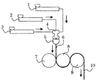
- the resin composition (A) is 65 mm ⁇ single screw extruder 2 (manufactured by Toshiba Machine Co., Ltd.), and the resin compositions (B) and (C) are 45 mm ⁇ single screw extruders 1 and 3 (manufactured by Hitachi Zosen Corporation). ] To melt each. Next, these are supplied to a three-type three-layer distribution type feed block 4 having a set temperature of 230 to 270 ° C.
- the film-like molten resin 6 was obtained by extruding from [Distribution] and laminating so as to have a structure represented by B layer / A layer / C layer.
- the obtained film-shaped molten resin 6 is sandwiched between a first cooling roll 7 (diameter 350 mm) and a second cooling roll 8 (diameter 450 mm) arranged opposite to each other, and is then wound around the second roll 8 while being wound around the second cooling roll 8.
- each layer has an average value of film thicknesses shown in Table 4
- the resin laminate 10 was obtained.
- Each of the obtained resin laminates 10 had a total film thickness of about 800 ⁇ m, and was visually transparent when visually observed.
- Table 5 shows the temperature of each cooling roll at the time of preparing the resin laminate, the take-off speed, and the discharged resin temperature measured with a non-contact thermometer for the resin discharged from the die.
- Table 6 shows the results of measuring ⁇ L, ⁇ B , ⁇ C , ⁇ BC and ⁇ T for the thermoplastic resin layers (B) and (C) of the resin laminates of Examples 1 to 3 and Comparative Examples 1 to 5. Shown in
- the alkali metal (Na and K) content in the intermediate layer (A) is 0.3 ppm in Examples 1 and 2 and Comparative Examples 1 to 5. In Example 3, it was 100 ppm.
- the dielectric constants of the resin laminates of Examples 1 to 3 and Comparative Examples 1 to 5 are 5.2 in Example 1 and Comparative Examples 2, 3, and 5, 5.3 in Example 2, and in Comparative Examples 1 and 4. 5.1, and in Example 3, it was 4.9. It was confirmed that any of the resin laminates has a dielectric constant sufficient for use in a display device such as a touch panel.
Landscapes
- Physics & Mathematics (AREA)
- Nonlinear Science (AREA)
- General Physics & Mathematics (AREA)
- Optics & Photonics (AREA)
- Mathematical Physics (AREA)
- Chemical & Material Sciences (AREA)
- Crystallography & Structural Chemistry (AREA)
- Engineering & Computer Science (AREA)
- Mechanical Engineering (AREA)
- Laminated Bodies (AREA)
- Polarising Elements (AREA)
Abstract
L'invention concerne un stratifié de résine qui est utilisé avantageusement dans un dispositif d'affichage et qui n'est pas susceptible de se déformer. Ce stratifié de résine comprend au moins une couche intermédiaire (A) et des couches de résine thermoplastique (B) et (C) qui sont présentes des deux côtés de la couche intermédiaire (A), la couche intermédiaire (A) contenant 10 à 90 % en masse d'une résine (méth)acrylique et de 90 à 10 % en masse d'une résine de fluorure de vinylidène sur la base de toutes les résines comprises dans la couche intermédiaire (A), la masse moléculaire moyenne en poids de la résine (méth)acrylique étant de 100 000 à 300 000, et les couches de résine thermoplastique (B) et (C) satisfaisant une relation particulière.
Priority Applications (2)
| Application Number | Priority Date | Filing Date | Title |
|---|---|---|---|
| KR1020187037736A KR102008473B1 (ko) | 2016-05-30 | 2017-05-22 | 수지 적층체, 표시 장치 및 편광판 |
| CN201780032646.XA CN109153245B (zh) | 2016-05-30 | 2017-05-22 | 树脂层叠体、显示装置及偏光板 |
Applications Claiming Priority (2)
| Application Number | Priority Date | Filing Date | Title |
|---|---|---|---|
| JP2016-107817 | 2016-05-30 | ||
| JP2016107817 | 2016-05-30 |
Publications (1)
| Publication Number | Publication Date |
|---|---|
| WO2017208881A1 true WO2017208881A1 (fr) | 2017-12-07 |
Family
ID=60477451
Family Applications (1)
| Application Number | Title | Priority Date | Filing Date |
|---|---|---|---|
| PCT/JP2017/019004 Ceased WO2017208881A1 (fr) | 2016-05-30 | 2017-05-22 | Stratifié de résine, dispositif d'affichage et polariseur |
Country Status (5)
| Country | Link |
|---|---|
| JP (1) | JP6503410B2 (fr) |
| KR (1) | KR102008473B1 (fr) |
| CN (1) | CN109153245B (fr) |
| TW (1) | TW201808638A (fr) |
| WO (1) | WO2017208881A1 (fr) |
Cited By (1)
| Publication number | Priority date | Publication date | Assignee | Title |
|---|---|---|---|---|
| WO2020071371A1 (fr) * | 2018-10-01 | 2020-04-09 | 大日本印刷株式会社 | Substrat transparent et élément de réglage de lumière |
Families Citing this family (1)
| Publication number | Priority date | Publication date | Assignee | Title |
|---|---|---|---|---|
| JP7497153B2 (ja) * | 2019-12-13 | 2024-06-10 | 日東電工株式会社 | 液晶パネル |
Citations (4)
| Publication number | Priority date | Publication date | Assignee | Title |
|---|---|---|---|---|
| JP2008535700A (ja) * | 2005-04-13 | 2008-09-04 | バイエル・マテリアルサイエンス・アクチェンゲゼルシャフト | 紫外線安定化成形ポリカーボネート製品 |
| WO2011142453A1 (fr) * | 2010-05-14 | 2011-11-17 | 三菱レイヨン株式会社 | Film, procédé pour produire celui-ci, film ou feuille stratifié(e), et stratifié |
| JP2012051311A (ja) * | 2010-09-03 | 2012-03-15 | Sumitomo Chemical Co Ltd | 熱可塑性樹脂押出板 |
| JP2013244604A (ja) * | 2012-05-23 | 2013-12-09 | Meihan Shinku Kogyo Kk | タッチスクリーン用透明シート、透明導電シート及びタッチスクリーン |
Family Cites Families (6)
| Publication number | Priority date | Publication date | Assignee | Title |
|---|---|---|---|---|
| JP2788756B2 (ja) * | 1989-06-15 | 1998-08-20 | 電気化学工業株式会社 | フッ素樹脂系着色フイルムとその製造方法 |
| JP2006305870A (ja) * | 2005-04-28 | 2006-11-09 | Teijin Dupont Films Japan Ltd | 二軸配向ポリエステルフィルム |
| JP5876207B2 (ja) * | 2009-12-16 | 2016-03-02 | エルジー ディスプレイ カンパニー リミテッド | タッチパネル装置およびタッチパネルのタッチ検出方法 |
| JP2014061705A (ja) * | 2012-08-31 | 2014-04-10 | Mitsubishi Rayon Co Ltd | 樹脂積層透明フィルム及び積層成形品 |
| US20160200884A1 (en) * | 2013-08-14 | 2016-07-14 | Mitsubishi Rayon Co., Ltd. | Film comprising vinylidene fluoride resin, laminated film, and laminate |
| WO2016042727A1 (fr) * | 2014-09-18 | 2016-03-24 | 株式会社クラレ | Procédé de production de feuille de résine extrudée et feuille de résine extrudée |
-
2017
- 2017-05-22 WO PCT/JP2017/019004 patent/WO2017208881A1/fr not_active Ceased
- 2017-05-22 CN CN201780032646.XA patent/CN109153245B/zh not_active Expired - Fee Related
- 2017-05-22 JP JP2017100895A patent/JP6503410B2/ja not_active Expired - Fee Related
- 2017-05-22 KR KR1020187037736A patent/KR102008473B1/ko not_active Expired - Fee Related
- 2017-05-24 TW TW106117157A patent/TW201808638A/zh unknown
Patent Citations (4)
| Publication number | Priority date | Publication date | Assignee | Title |
|---|---|---|---|---|
| JP2008535700A (ja) * | 2005-04-13 | 2008-09-04 | バイエル・マテリアルサイエンス・アクチェンゲゼルシャフト | 紫外線安定化成形ポリカーボネート製品 |
| WO2011142453A1 (fr) * | 2010-05-14 | 2011-11-17 | 三菱レイヨン株式会社 | Film, procédé pour produire celui-ci, film ou feuille stratifié(e), et stratifié |
| JP2012051311A (ja) * | 2010-09-03 | 2012-03-15 | Sumitomo Chemical Co Ltd | 熱可塑性樹脂押出板 |
| JP2013244604A (ja) * | 2012-05-23 | 2013-12-09 | Meihan Shinku Kogyo Kk | タッチスクリーン用透明シート、透明導電シート及びタッチスクリーン |
Cited By (2)
| Publication number | Priority date | Publication date | Assignee | Title |
|---|---|---|---|---|
| WO2020071371A1 (fr) * | 2018-10-01 | 2020-04-09 | 大日本印刷株式会社 | Substrat transparent et élément de réglage de lumière |
| JP6711473B1 (ja) * | 2018-10-01 | 2020-06-17 | 大日本印刷株式会社 | 透明基材、調光部材 |
Also Published As
| Publication number | Publication date |
|---|---|
| KR102008473B1 (ko) | 2019-08-07 |
| CN109153245B (zh) | 2020-05-05 |
| KR20190007071A (ko) | 2019-01-21 |
| CN109153245A (zh) | 2019-01-04 |
| JP2017213879A (ja) | 2017-12-07 |
| JP6503410B2 (ja) | 2019-04-17 |
| TW201808638A (zh) | 2018-03-16 |
Similar Documents
| Publication | Publication Date | Title |
|---|---|---|
| JP6395899B2 (ja) | 樹脂積層体の製造方法 | |
| JP6337974B2 (ja) | 樹脂組成物、膜及び表示装置 | |
| JP6395898B2 (ja) | 保護フィルム付き樹脂積層体 | |
| JP6591492B2 (ja) | 樹脂積層体の製造方法 | |
| JP6407918B2 (ja) | 樹脂積層体、表示装置及び偏光板 | |
| JP6420925B1 (ja) | 曲面状樹脂積層体 | |
| JP6461065B2 (ja) | 樹脂積層体及びその製造方法 | |
| JP6503410B2 (ja) | 樹脂積層体、表示装置及び偏光板 | |
| JP6360630B2 (ja) | 樹脂組成物、膜、タッチセンサーパネル及び表示装置 | |
| WO2016199829A1 (fr) | Composition de résine, film, écran tactile et dispositif d'affichage |
Legal Events
| Date | Code | Title | Description |
|---|---|---|---|
| 121 | Ep: the epo has been informed by wipo that ep was designated in this application |
Ref document number: 17806438 Country of ref document: EP Kind code of ref document: A1 |
|
| NENP | Non-entry into the national phase |
Ref country code: DE |
|
| ENP | Entry into the national phase |
Ref document number: 20187037736 Country of ref document: KR Kind code of ref document: A |
|
| 122 | Ep: pct application non-entry in european phase |
Ref document number: 17806438 Country of ref document: EP Kind code of ref document: A1 |