WO2017209032A1 - Réfrigérateur - Google Patents
Réfrigérateur Download PDFInfo
- Publication number
- WO2017209032A1 WO2017209032A1 PCT/JP2017/019871 JP2017019871W WO2017209032A1 WO 2017209032 A1 WO2017209032 A1 WO 2017209032A1 JP 2017019871 W JP2017019871 W JP 2017019871W WO 2017209032 A1 WO2017209032 A1 WO 2017209032A1
- Authority
- WO
- WIPO (PCT)
- Prior art keywords
- compartment
- refrigerator
- chamber
- cold air
- duct
- Prior art date
- Legal status (The legal status is an assumption and is not a legal conclusion. Google has not performed a legal analysis and makes no representation as to the accuracy of the status listed.)
- Ceased
Links
Images











Classifications
-
- F—MECHANICAL ENGINEERING; LIGHTING; HEATING; WEAPONS; BLASTING
- F25—REFRIGERATION OR COOLING; COMBINED HEATING AND REFRIGERATION SYSTEMS; HEAT PUMP SYSTEMS; MANUFACTURE OR STORAGE OF ICE; LIQUEFACTION SOLIDIFICATION OF GASES
- F25D—REFRIGERATORS; COLD ROOMS; ICE-BOXES; COOLING OR FREEZING APPARATUS NOT OTHERWISE PROVIDED FOR
- F25D17/00—Arrangements for circulating cooling fluids; Arrangements for circulating gas, e.g. air, within refrigerated spaces
- F25D17/04—Arrangements for circulating cooling fluids; Arrangements for circulating gas, e.g. air, within refrigerated spaces for circulating air, e.g. by convection
- F25D17/06—Arrangements for circulating cooling fluids; Arrangements for circulating gas, e.g. air, within refrigerated spaces for circulating air, e.g. by convection by forced circulation
- F25D17/08—Arrangements for circulating cooling fluids; Arrangements for circulating gas, e.g. air, within refrigerated spaces for circulating air, e.g. by convection by forced circulation using ducts
Definitions
- This disclosure relates to a refrigerator including a vegetable room damper.
- a refrigerator cold air is generated in a cooling chamber on the back of the refrigerator body, and the cold air is circulated to a refrigerator compartment, a freezer compartment, a vegetable compartment, etc. by a blower (for example, a cooling fan), and food in each room is cooled. It is comprised so that.
- a refrigerator that is equipped with a refrigeration room damper that controls the amount of cold air circulation to the refrigeration room and a vegetable room damper that controls the amount of cold air circulation to the vegetable room so that the vegetable room can be cooled efficiently.
- a refrigeration room damper that controls the amount of cold air circulation to the refrigeration room
- a vegetable room damper that controls the amount of cold air circulation to the vegetable room so that the vegetable room can be cooled efficiently.
- FIG. 32 shows the refrigerator described in Patent Document 1.
- the cooling chamber 101 is disposed on the back surface of the freezing chamber 102, and cold air is generated in the cooling chamber 101.
- the cold air generated in the cooling chamber 101 is supplied from the cold air passage portion 105 to the refrigerating chamber 103 via the refrigerating chamber duct 106.
- the cool air passage portion 105 is provided in a portion of the partition plate 104 that partitions the refrigerator compartment 103 and the freezer compartment 102, facing the upper surface of the cooling chamber 101.
- the cold air is supplied to the vegetable compartment 108 through the vegetable compartment duct 107 branched from the middle of the cold air passage section 105.
- a refrigerator compartment damper 109 is incorporated in a connection portion of the refrigerator compartment duct 106 to the partition plate 104.
- a vegetable compartment damper 110 is incorporated in a branch portion of the cold air passage 105 to the vegetable compartment duct 107 formed in the partition plate 104. With such a configuration, the amount of cold air supplied to the refrigerator compartment 103 and the vegetable compartment 108 is controlled.
- a cooling fan 111 and a cooler 112 are arranged in the cooling chamber 101.
- the amount of cold air supplied to the vegetable compartment 108 can be controlled independently of the supply of cold air to the refrigerator compartment 103. For this reason, there is an advantage that the inside of the vegetable compartment 108 can be effectively cooled without being overcooled or dried.
- the cold air is branched and supplied to the vegetable compartment 108 from the middle of the cold air passage portion 105 that supplies the cold air from the cooling chamber 101 to the refrigerator compartment 103.
- opening and closing of the vegetable compartment damper 110 changes the amount of cold air supplied to the refrigerating chamber 103, resulting in variations in the cooling performance of the refrigerating chamber 103.
- the vegetable compartment damper 110 when the vegetable compartment damper 110 is closed, the entire amount of cold air from the cooling chamber 101 supplied through the cold air passage portion 105 is supplied to the refrigerator compartment 103. However, when the vegetable compartment damper 110 is opened, a part of the cold air from the cooling chamber 101 supplied through the cold air passage portion 105 branches to the vegetable compartment duct 110 and flows into the vegetable compartment 108, and accordingly. The amount of cold air to the refrigerator compartment 103 decreases, and the cooling performance of the refrigerator compartment 103 varies.
- the cold air from the cooling chamber 101 to the vegetable chamber 108 is blown up to a branch portion provided in the cold air passage portion 105 of the partition plate 104 above the cooling chamber 101 and then supplied to the vegetable chamber 108 below the cooling chamber 101. Is done. Therefore, the vegetable compartment duct 107 has a long overall length and a large passage resistance. For this reason, in such a conventional refrigerator 100, when the vegetable compartment damper 110 is opened and the vegetable compartment 108 is cooled, the whole cold air circulation amount falls and there exists a subject that cooling capacity falls.
- the refrigerator is provided with a freezer damper that adjusts the amount of cold air circulation to the freezer room and a freezer compartment damper that controls the amount of cold air circulation to the freezer room, so that the refrigerator room and freezer room can be efficiently cooled.
- a freezer damper that adjusts the amount of cold air circulation to the freezer room
- a freezer compartment damper that controls the amount of cold air circulation to the freezer room, so that the refrigerator room and freezer room can be efficiently cooled.
- some refrigerators are provided at the lower part of the refrigerating room, have a container and a top plate, and have a low temperature room set in a temperature zone lower than that of the refrigerating room (see, for example, Patent Document 3).
- the air that has cooled the refrigerator compartment flows into the container of the cold room from the gap between the lower part of the container of the cold room and the bottom of the refrigerator room, or the gap between the container of the cold room and the top plate, After flowing through the container of the low greenhouse, it flows to the back of the low temperature chamber and returns to the cooling chamber from the return air passage on the back of the partition at the bottom of the refrigerator compartment.
- the flow area of the refrigerator compartment duct is: It is comprised so that the downstream side may become wider than the upstream side of cold air (for example, refer patent document 4).
- This disclosure provides a refrigerator that stabilizes the amount of cold air supplied to the refrigerator compartment and improves the cooling performance of the refrigerator compartment regardless of whether the vegetable compartment damper is opened or closed.
- a refrigerator includes a refrigerator body, a refrigerator room, a freezer room and a vegetable room arranged in the refrigerator body, a rear part of the freezer room, the refrigerator room, the freezer room A cooling room for generating cold air to be supplied to each of the vegetable rooms, a cold room duct for guiding the cold air from the cooling room to the cold room, and a vegetable room duct for guiding the cold air from the cooling room to the vegetable room .
- the refrigerator compartment duct is provided with a refrigerator compartment damper
- the vegetable compartment duct is provided with a vegetable compartment damper.
- a refrigerator is configured such that the amount of cold air supplied to the refrigerator compartment and the vegetable compartment can be controlled by opening and closing each damper (refrigerator compartment damper and vegetable compartment damper). Further, the refrigerator compartment duct provided with the refrigerator compartment damper and the vegetable compartment duct provided with the vegetable compartment damper are connected to the cooling chambers independently of each other at different positions of the cooling chamber.
- the cold air from the cooling room is supplied to the refrigerating room duct and the vegetable room duct in an independent manner.
- the amount of cold air supplied to the refrigerator compartment duct is not affected by the opening and closing, and the cooling air supply amount to the refrigerator compartment is stabilized and the cooling performance is improved. be able to.
- the vegetable compartment duct may be connected to the cooling room within the rear projection plane of the freezing room located in front of the cooling room.
- the vegetable compartment duct does not pass through the partition plate portion that partitions the refrigerator compartment and freezer compartment above the cooling compartment. Therefore, with such a configuration, the length of the vegetable compartment duct can be shortened and the passage resistance can be reduced. Thereby, the amount of cold air circulation can be increased and the cooling performance can be improved.
- the refrigerator may be configured such that the vegetable room damper is incorporated in the vegetable room duct and is located in the rear projection plane of the freezer room together with the vegetable room duct. .
- the vegetable compartment damper can also be incorporated into the refrigerator body simply by installing the vegetable compartment duct in the refrigerator body, and a location different from the vegetable compartment duct, for example, between the refrigerator compartment and the freezer compartment.
- Productivity can be greatly improved compared with the case where a vegetable compartment damper is separately incorporated in the partition plate.
- the vegetable compartment duct is connected to the cooling chamber within the rear projection plane of the freezing compartment located in front of the cooling compartment, the length of the vegetable compartment duct can be shortened and the passage resistance can be reduced. The amount of cold air circulation can be increased, and the cooling performance can be improved.
- the cooling chamber includes a cooler and a cooling fan positioned above the cooler, and the vegetable chamber damper is provided at a height that overlaps the cooling fan. It may be done.
- the vegetable compartment duct can be shortened by a length that passes through the partition plate above the cooling chamber that partitions the refrigerator compartment and the freezer compartment, reduces passage resistance, and cool air circulation rate.
- the cooling performance can be improved.
- the distance from the vegetable compartment to the vegetable compartment damper can be ensured by the height of the cooler.
- the vegetable compartment duct may be disposed so as to overlap with the refrigerator compartment return duct from the refrigerator compartment to the refrigerator compartment in the front-rear direction.
- the vegetable compartment duct and the refrigeration compartment return duct may each be formed of an elastic material.
- the refrigerator by an example of embodiment of this indication may be comprised so that a vegetable compartment damper may be clamped with a vegetable compartment duct and a refrigerator compartment return duct.
- the vegetable room damper can be rationally incorporated into the vegetable room duct using the refrigeration room return duct. Furthermore, the elastic force of the vegetable room duct and the refrigeration room return duct can ensure airtightness, does not require a sealing member for ensuring airtightness when separately incorporated in the partition plate, and simplifies the configuration. Productivity can be improved.
- the present disclosure also provides a refrigerator that can suppress the space around the cooler storage chamber (cooling chamber) and increase the internal volume efficiency.
- the refrigerator includes a refrigerator compartment, a freezer compartment, a cooling chamber disposed behind the freezer compartment, and a supply amount of cold air supplied from the refrigerator compartment to the refrigerator compartment. And a freezer compartment damper provided in a cool air return passage portion through which cool air supplied to the freezer chamber is returned to the cooler chamber.
- the refrigerator according to an example of the embodiment of the present disclosure is configured such that a damper is not provided in the cold air discharge passage supplied from the cooling chamber to the freezing chamber, and the cooling chamber and the freezing chamber are maintained in a communication state. Yes.
- the space around the cooler storage chamber (cooling chamber) can be suppressed without increasing the space of the cool air discharge air passage, and the volumetric efficiency in the refrigerator can be reduced. Can be increased.
- a freezer compartment damper may be disposed on a partition plate (freezer compartment back plate) that partitions the freezer compartment and the cooling compartment.
- the freezer compartment damper includes a frame body, a drive device, and a flap, and the freezer compartment damper is rotated toward the cooling chamber by the drive device. It may be configured as follows. With such a configuration, the space around the cooler storage chamber can be further suppressed, and the internal volumetric efficiency can be increased.
- the freezer compartment damper may include a plurality of flaps, and the plurality of flaps may be opened and closed by a driving device.
- the freezer damper is arranged such that the frame body and the flap are inclined toward the cooling chamber with reference to a vertical plane parallel to the front surface or the back surface of the refrigerator. May be.
- drainage performance such as defrost water adhering to the freezer compartment damper can be improved, and the reliability of the freezer compartment damper can be improved.
- the refrigerator according to an example of the embodiment of the present disclosure may further include a refrigeration room return duct for returning the cold air supplied to the refrigeration room to the cooling room at the side of the cooler.
- the drive unit and the flap of the freezer compartment damper are provided side by side, and the drive unit may be disposed on the refrigerator return duct side when viewed from the front of the refrigerator. Good. With such a configuration, the left-right bias of the freezer damper with respect to the cooler can be improved, and the cooling efficiency can be increased.
- the refrigerator according to an example of the embodiment of the present disclosure may further include a glass tube heater provided below the cooling chamber.
- the outer shell (frame body) of the freezer compartment damper may be made of a heat-resistant material that can withstand the heat from the glass tube heater.
- the refrigerator according to an example of the embodiment of the present disclosure may further include a heater cover provided above the glass tube heater.
- a part of the heater cover may be interposed between the glass tube heater and the freezer damper.
- the present disclosure also provides a refrigerator that is not easily affected by load fluctuations in the refrigerator compartment and can stably maintain the temperature in the low-temperature compartment at a predetermined temperature.
- a refrigerator includes a refrigerator compartment, a freezer compartment, a partition plate that partitions the refrigerator compartment and the freezer compartment, a cooling compartment disposed behind the freezer compartment, and a refrigerator.
- a low-temperature chamber (for example, a partial chamber) provided in the lower part of the chamber, and a refrigerating chamber duct for supplying cold air to the refrigerating chamber and the low-temperature chamber respectively.
- the low greenhouse is partitioned by a ceiling plate in the refrigerating room, has a container inside, and is maintained in a temperature range lower than that of the refrigerating room.
- the refrigerator includes a cold air return port (first cold air return port and second cold air return port) provided in each of the partition plate and the ceiling plate, and cold air returning from the refrigerator compartment to the cooling chamber. And a cold air return passage portion through which the air passes.
- the cool air returning from the refrigerator compartment to the cool chamber is returned from the cool air return port (first cold air return port) provided in the ceiling plate to the cooler return space provided in the space outside the container in the low temperature chamber and the partition plate. It is configured so as to be returned to the cooling chamber through the mouth (second cold air return port).
- air having a relatively high temperature after cooling the refrigerating room flows outside the container in the low temperature room, and is not easily affected by load fluctuations in the refrigerating room, and is stably in the low temperature room.
- the temperature can be maintained at a predetermined temperature.
- the cold air return port provided in the ceiling plate and the cold air return port provided in the partition plate are shifted from each other in the left-right direction when viewed from the front of the refrigerator. It may be arranged. With such a configuration, dust or the like that has entered the cold air return port provided on the ceiling plate from the refrigerator compartment does not directly drop into the cold air return port provided on the partition plate, and the dust or the like can enter the cold air return port. Adverse effects can be reduced and stable cooling capacity of the refrigerator compartment can be secured.
- a refrigerator includes a cold room damper that controls supply of cold air to the cold room, a cold room temperature sensor, a low temperature room damper that controls supply of cold air to the low temperature room, and a low temperature room. And a temperature sensor.
- the refrigerating room temperature sensor and the low temperature room temperature sensor may be disposed in the refrigerating room duct. With such a configuration, the assembly process can be simplified.
- the refrigerator temperature sensor and the cold room temperature sensor may be arranged to face each other in the left-right direction of the refrigerator compartment duct.
- the temperature in the refrigerator compartment is controlled by detecting the return air from the refrigerator compartment. Therefore, the low temperature chamber temperature sensor is less affected by the return air from the refrigerator compartment and is more stable.
- the temperature in the low temperature chamber can be maintained at a predetermined temperature.
- the present disclosure provides a design of a cold room duct while appropriately setting an aspect ratio (long side / short side) represented by a ratio between a long side and a short side in a horizontal section of the air path of the cold room duct.
- a refrigerator capable of ensuring cooling performance without impairing the performance is also provided.
- a refrigerator includes a freezer compartment, a refrigerator compartment disposed at the top of the freezer compartment, a cooling compartment disposed behind the freezer compartment, and a refrigerator compartment rear surface.
- a cold room duct and a cold room damper, and a low temperature room disposed in a lower part of the cold room and maintained in a temperature range lower than that of the cold room.
- the aspect ratio (long side / short side) represented by the ratio of the long side to the short side in the horizontal cross section of the air path of the cold room duct has the cold room damper portion.
- the low temperature chamber portion and the refrigeration chamber portion are set to increase in order.
- the effective internal volume of the refrigerator can be increased while appropriately setting the aspect ratio of the refrigerator compartment duct, and the cooling performance can be ensured without impairing the design of the refrigerator compartment duct.
- the refrigerator compartment duct may have a discharge port on a side surface and a rib that covers the discharge port on a front side portion.
- the lower surface of the discharge port may have an inclined surface that is upward with respect to the flow of cold air.
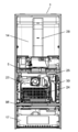
- FIG. 1 is a top view of the appearance seen from the front of the refrigerator of an embodiment of this indication.
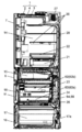
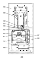
- FIG. 2 is a plan view of the inside of the refrigerator according to the embodiment of the present disclosure as viewed from the front.
- Drawing 3 is a sectional view which looked at the section cut in the up-and-down direction of the refrigerator of an embodiment of this indication from the side.
- FIG. 4 is a diagram for explaining a cold air flow of the refrigerator according to the embodiment of the present disclosure.
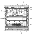
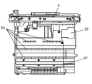
- FIG. 5 is a plan view of the freezer compartment portion of the refrigerator according to the embodiment of the present disclosure as viewed from the front.
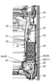
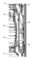
- 6 is a cross-sectional view of the refrigerator according to the embodiment of the present disclosure, as viewed from the side, in the cooling chamber section cut along the line 6-6 in FIG.
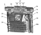
- FIG. 7 is a cross-sectional view of the refrigerator of the embodiment of the present disclosure as viewed from the side of the vegetable compartment duct portion and the refrigeration compartment return duct portion cut in the vertical direction along line 7-7 in FIG.
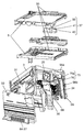
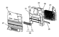
- FIG. 8 is an exploded perspective view illustrating a cooling chamber portion of the refrigerator according to the embodiment of the present disclosure.
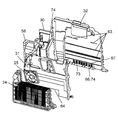
- FIG. 9 is an exploded perspective view of the cooling chamber portion of the refrigerator according to the embodiment of the present disclosure as viewed from the cooling chamber side.
- FIG. 10 is a perspective view of the cooling chamber in a state where a part of the cooling chamber forming plate of the refrigerator according to the embodiment of the present disclosure remains from the cooling chamber side.
- FIG. 11 is a plan view of the relationship between the cooling chamber forming plate and the vegetable compartment duct of the refrigerator according to the embodiment of the present disclosure as viewed from the freezer compartment side.
- FIG. 12 is a perspective view illustrating the relationship between the cooling chamber forming plate and the vegetable chamber duct of the refrigerator according to the embodiment of the present disclosure as viewed from the freezer compartment side.
- FIG. 13 is a perspective view illustrating the refrigerator compartment of the refrigerator according to the embodiment of the present disclosure.
- FIG. 14A is a cross-sectional view illustrating a cross-section cut in the vertical direction of the refrigerator compartment portion of the refrigerator according to the embodiment of the present disclosure.
- FIGS. 14A to 14C are diagrams schematically showing cross sections cut in the horizontal direction of A part, B part, and C part of FIG.
- FIG. 14A is a cross-sectional view showing a cross section cut in the horizontal direction of the refrigerator compartment duct of the refrigerator according to the embodiment of the present disclosure.
- FIG. 14D is a diagram for describing a structure and a function of a discharge port of the refrigerator compartment duct of the refrigerator according to the embodiment of the present disclosure.
- FIG. 15 is an essential part enlarged cross-sectional view showing the refrigerator compartment of the refrigerator according to the embodiment of the present disclosure.
- FIG. 16 is a plan view when the refrigerator compartment of the refrigerator according to the embodiment of the present disclosure is viewed from the front of the refrigerator.
- FIG. 17 is an enlarged front view illustrating a main part of the refrigerator compartment of the refrigerator according to the embodiment of the present disclosure.
- FIG. 18 is an exploded perspective view illustrating the refrigerator compartment of the refrigerator according to the embodiment of the present disclosure.
- FIG. 19 is a perspective view of the rear part of the partial chamber in the refrigerator compartment of the refrigerator according to the embodiment of the present disclosure as viewed from the back side of the refrigerator.
- FIG. 20 is an enlarged perspective view of a rear portion of the partial chamber in the refrigerator compartment of the refrigerator according to the embodiment of the present disclosure as viewed from the back side of the refrigerator.
- FIG. 21 is another enlarged perspective view of the rear portion of the partial chamber in the refrigerator compartment of the refrigerator according to the embodiment of the present disclosure as viewed from the back side of the refrigerator.
- FIG. 19 is a perspective view of the rear part of the partial chamber in the refrigerator compartment of the refrigerator according to the embodiment of the present disclosure as viewed from the back side of the refrigerator.
- FIG. 20 is an enlarged perspective view of a rear portion of the partial chamber in the refrigerator compartment of the refrigerator according to the embodiment of the present disclosure as viewed from the back side of the refrigerator.
- FIG. 22 is an enlarged side view showing a deodorizing unit mounting portion at the rear of the partial chamber in the refrigerator compartment of the refrigerator according to the embodiment of the present disclosure.
- FIG. 23 is an enlarged perspective view illustrating a deodorizing unit mounting portion at the rear of the partial chamber in the refrigerator compartment of the refrigerator according to the embodiment of the present disclosure.
- FIG. 24 is a perspective view of the cooling chamber viewed from the back side with the refrigerator cooler of the embodiment of the present disclosure removed.
- FIG. 25 is a plan view of the cooling chamber viewed from the back side with the refrigerator cooler of the embodiment of the present disclosure removed.
- FIG. 26 is a plan view of the back plate of the freezer compartment of the refrigerator according to the embodiment of the present disclosure as viewed from the front.
- FIG. 27 is an exploded perspective view of the cooling chamber components of the refrigerator according to the embodiment of the present disclosure.
- FIG. 28 is a perspective view of the cooling chamber of the refrigerator according to the embodiment of the present disclosure as viewed obliquely from the upper front.
- FIG. 29 is an enlarged cross-sectional view illustrating a main part of the cooling chamber of the refrigerator according to the embodiment of the present disclosure.
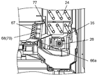
- FIG. 30 is an enlarged cross-sectional view of another example illustrating the main part of the cooling chamber of the refrigerator according to the embodiment of the present disclosure.
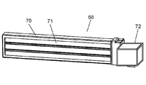
- FIG. 31A is a perspective view illustrating the freezer damper of the refrigerator according to the embodiment of the present disclosure.
- FIG. 31B is a cross-sectional view of the freezer compartment damper of the refrigerator according to the embodiment of the present disclosure.
- FIG. 32 is a diagram for explaining a cold air flow of a conventional refrigerator.
- FIG. 1 to 4 are diagrams for describing the overall configuration of the refrigerator according to the embodiment of the present disclosure.
- FIG. 5 to FIG. 12 are diagrams for explaining a structure for supplying cold air from the cooling chamber of the refrigerator according to the embodiment of the present disclosure to the vegetable compartment.
- 13 to 23 are diagrams for describing the refrigerator compartment configuration of the refrigerator according to the embodiment of the present disclosure.
- FIGS. 24 to 31 are diagrams for describing a configuration of a portion extending from the freezer compartment to the cooling compartment of the refrigerator according to the embodiment of the present disclosure.
- the front means the front direction of the refrigerator
- the rear means the rear direction of the refrigerator
- the upper direction means the top direction of the refrigerator
- FIG. 1 is a plan view of the appearance of a refrigerator according to an embodiment of the present disclosure as viewed from the front.
- FIG. 2 is a plan view of the inside of the refrigerator according to the embodiment of the present disclosure as viewed from the front.
- Drawing 3 is a sectional view which looked at the section cut in the up-and-down direction of the refrigerator of an embodiment of this indication from the side.
- FIG. 4 is a diagram for explaining a cold air flow of the refrigerator according to the embodiment of the present disclosure.
- a refrigerator 90 according to an example of the embodiment of the present disclosure includes a refrigerator body 1 having an opening at the front.
- the refrigerator main body 1 includes a metal outer box 2, a hard resin inner box 3, and a foam insulation 4 filled between the outer box 2 and the inner box 3.
- the inside of the refrigerator body 1 is partitioned by partition plates 5, 96 and the like, and a plurality of storage rooms are formed.
- Each storage chamber of the refrigerator body 1 is configured to be openable and closable by a pivotable door 97 and drawer-type doors 8, 9, 10, and 11 adopting the same heat insulation structure as the refrigerator body 1.
- the plurality of storage chambers formed in the refrigerator main body 1 are provided next to the uppermost refrigeration chamber 14, a switching chamber 15 provided under the refrigeration chamber 14 and capable of switching a temperature zone, and the switching chamber 15.
- the ice making room 16, the switching room 15, the ice making room 16, and the freezing room 18 provided between the lowermost vegetable room 17 and the lowermost vegetable room 17 are configured.
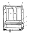
- the refrigerator compartment 14 is provided with a plurality of shelf boards 20. In the lower part of the refrigerator compartment 14, a partial chamber 21 and a chilled chamber 22 having different cooling temperature zones are provided so as to be stacked in two upper and lower stages.
- the refrigerated room 14 is a storage room for refrigerated storage of foods and the like, and is set at a low temperature such that the foods and the like are not frozen, specifically, usually set to 1 to 5 ° C. and cooled.
- the partial chamber 21 provided in the refrigerator compartment 14 is set to a temperature suitable for micro freezing storage, for example, ⁇ 2 to ⁇ 3 ° C.
- the chilled chamber 22 is set to a temperature lower than the refrigerated chamber 14 and higher than the partial chamber 21, for example, around 1 ° C., and is cooled.
- the vegetable room 17 is a storage room that is set to a temperature that is equal to or slightly higher than that of the refrigerator room 14, and is specifically set to 2 to 7 ° C. and cooled. Since the vegetable compartment 17 becomes high humidity due to moisture emitted from stored foods such as vegetables, condensation may occur if it is locally cooled. For this reason, the vegetable compartment 17 is configured to reduce the amount of cooling by being set at a relatively high temperature and to suppress the occurrence of condensation due to local overcooling.
- the freezing room 18 is a storage room set in a freezing temperature zone, and is specifically set to ⁇ 22 to ⁇ 18 ° C. and cooled. However, in order to improve the frozen storage state, the temperature may be set to a low temperature such as ⁇ 30 ° C. or ⁇ 25 ° C. and cooled.
- the switching chamber 15 is a storage chamber in which the temperature in the warehouse can be changed, and is configured to be switched from a refrigeration temperature zone to a freezing temperature zone according to the application.
- a cooling chamber 23 is provided on the back of the freezing chamber 18.
- the cooling chamber 23 is provided with a cooler 24 that generates cool air and a cooling fan 25 that supplies the cool air to each chamber.
- a defrosting section hereinafter referred to as a glass tube heater 26 composed of a glass tube heater or the like is provided below the cooler 24.
- the cooler 24 includes a compressor 27, a condenser (not shown), a heat radiating pipe (not shown), and a capillary tube (not shown) connected in a ring shape to form a refrigeration cycle. Then, cooling is performed by circulation of the refrigerant compressed by the compressor 27.
- the cooling fan 25 is provided above the cooler 24.
- the cooling fan 25 cools the refrigerator compartment 14, the refrigerator compartment 18, the vegetable compartment 17, and the like through the refrigerator compartment duct 28, the freezer compartment duct 29 (FIG. 6), and the vegetable compartment duct 30 that are connected to the downstream side of the cooling fan 25. To cool each of these chambers.
- each of the cooling chamber 23, the refrigerator compartment 14, the freezer compartment 18, and the vegetable compartment 17, and the cooling configuration of each chamber will be described.
- Cooling chamber and cool air supply configuration The cooling chamber 23 and the cold air supply configuration will be described with reference to FIGS. 3, 5 to 11 and FIG.
- FIG. 5 is a plan view of the freezer compartment portion of the refrigerator according to the embodiment of the present disclosure as viewed from the front.
- 6 is a cross-sectional view of the refrigerator according to the embodiment of the present disclosure, as viewed from the side, in the cooling chamber section cut along the line 6-6 in FIG.
- FIG. 7 is a cross-sectional view of the refrigerator of the embodiment of the present disclosure as viewed from the side of the vegetable compartment duct portion and the refrigeration compartment return duct portion cut in the vertical direction along line 7-7 in FIG.
- FIG. 8 is an exploded perspective view illustrating a cooling chamber portion of the refrigerator according to the embodiment of the present disclosure.
- FIG. 9 is an exploded perspective view of the cooling chamber portion of the refrigerator according to the embodiment of the present disclosure as viewed from the cooling chamber side.
- FIG. 10 is a perspective view of the cooling chamber in a state where a part of the cooling chamber forming plate of the refrigerator according to the embodiment of the present disclosure remains from the cooling chamber side.
- FIG. 11 is a plan view of the relationship between the cooling chamber forming plate and the vegetable compartment duct of the refrigerator according to the embodiment of the present disclosure as viewed from the freezer compartment side.
- FIG. 12 is a perspective view illustrating the relationship between the cooling chamber forming plate and the vegetable chamber duct of the refrigerator according to the embodiment of the present disclosure as viewed from the freezer compartment side.
- the cooling chamber 23 is provided on the back surface of the freezing chamber 18 and includes a cooling chamber forming plate 31 and an inner box 3.
- a cooling fan 25 is mounted on the upper part of the cooling chamber forming plate 31, and the cooling fan 25 is disposed above the cooler 24.
- a freezer compartment back plate (partition plate) 32 is mounted on the front side of the cooling chamber forming plate 31, and the freezer compartment back plate 32 is disposed so as to cover the downstream side of the cooling fan 25.
- a freezer compartment duct 29 that communicates with the downstream side of the cooling fan 25 is formed between the freezer compartment back plate 32 and the cooling compartment 23.
- the refrigerator compartment duct 28 of the refrigerator compartment 14 and the vegetable compartment duct 30 of the vegetable compartment 17 are connected to the cooling compartment 23 separately at different positions.
- the upper surface of the cooling chamber 23 on the downstream side of the cooling fan 25 is, as shown in FIG. 4 and the like, the first cold air supply provided in the partition plate 5 that partitions the refrigerator compartment 14 and the freezer compartment 18. It is connected to the refrigerator compartment duct 28 through the port 33.
- a second cold air supply port 34 is provided on the downstream side of the cooling fan 25 and on the side of the cooling chamber 23.
- the vegetable compartment duct 30 is connected to the That is, the refrigerator compartment duct 28 and the vegetable compartment duct 30 are connected to each other at different positions in the cooling chamber 23 in a mutually independent manner.
- the cold air generated by the cooler 24 is supplied to the first cold air supply port 33 and the second cold air supply port 34 by the cooling fan 25 in a separate and independent manner, and the cold room duct 28 and the vegetable room duct 30 are supplied. Supplied to each.
- a heater cover 35 having an umbrella-like cross section that covers the glass tube heater 26 is installed, and defrost water is placed outside on the bottom surface of the cooling chamber 23.
- a drain port 36 for discharging is provided.
- FIG. 13 is a perspective view showing the refrigerator compartment of the refrigerator according to the embodiment of the present disclosure.
- FIG. 14A is a cross-sectional view illustrating a cross-section cut in the vertical direction of the refrigerator compartment portion of the refrigerator according to the embodiment of the present disclosure.
- FIG. 14B is a diagram schematically illustrating a cross section cut in a horizontal direction of a portion A in FIG. 14A according to the embodiment of the present disclosure.
- FIG. 14B is a diagram schematically illustrating a cross section cut in a horizontal direction with a portion B in FIG. 14A according to the embodiment of the present disclosure.
- FIG. 14B (c) is a diagram schematically showing a cross section cut in a horizontal direction of a portion C in FIG. 14A according to the embodiment of the present disclosure.
- FIG. 14A is a cross-sectional view illustrating a cross-section cut in the vertical direction of the refrigerator compartment portion of the refrigerator according to the embodiment of the present disclosure.
- FIG. 14B is a diagram schematically
- FIG. 14C is a cross-sectional view showing a cross section cut in the horizontal direction of the refrigerator compartment duct of the refrigerator according to the embodiment of the present disclosure.
- FIG. 14D is a diagram for describing a discharge port of the refrigerator compartment duct of the refrigerator according to the embodiment of the present disclosure.
- FIG. 15 is an essential part enlarged cross-sectional view showing the refrigerator compartment of the refrigerator according to the embodiment of the present disclosure.
- FIG. 16 is a front view illustrating the inside of the refrigerator compartment of the refrigerator according to the embodiment of the present disclosure.
- FIG. 17 is an enlarged front view illustrating a main part of the refrigerator compartment of the refrigerator according to the embodiment of the present disclosure.
- FIG. 18 is an exploded perspective view illustrating a storage room of the refrigerator according to the embodiment of the present disclosure.
- FIG. 19 is a perspective view of the rear portion of the partial chamber in the storage chamber of the refrigerator according to the embodiment of the present disclosure as viewed from the back.
- FIG. 20 is an enlarged perspective view of a rear portion of the partial chamber in the storage chamber of the refrigerator according to the embodiment of the present disclosure as viewed from the back.
- FIG. 21 is an enlarged perspective view of the rear portion of the partial chamber in the storage chamber of the refrigerator according to the embodiment of the present disclosure as viewed from the front-side back portion.
- FIG. 22 is an enlarged side view showing a deodorizing unit mounting portion at the rear of the partial chamber in the refrigerator storage chamber according to the embodiment of the present disclosure.
- the refrigerator compartment 14 is located at the uppermost part of the refrigerator main body 1 and has a plurality of shelf boards 20 as shown in FIGS. 3 and 14A to 14D.
- a refrigerator compartment duct 28 is provided on the back of the refrigerator compartment 14.
- the refrigerator compartment duct 28 is composed of a duct member 28a and a duct cover 28b. Specifically, as shown in FIG. 18, the refrigerator compartment duct 28 is configured by covering the refrigerator compartment side surface of a duct member 28a made of foamed polystyrene with a resin duct cover 28b. Further, as shown in FIGS. 3 and 4, the refrigerator compartment duct 28 is provided on the back of the refrigerator compartment 14 so as to cover the first cold air supply port 33 of the partition plate 5 that partitions the refrigerator compartment 14 and the freezer compartment 18. It is mounted and communicates with the cooling chamber 23. As shown in FIG. 4, a cold room damper 37 is incorporated in the first cold air supply port 33.
- the refrigerator 90 is configured such that the amount of cold air supplied from the cooling chamber 23 to the refrigerator compartment 14 is controlled by opening and closing the refrigerator compartment damper 37.
- the refrigerating room damper 37 is fixed to the first cold air supply port 33 by a damper fixing frame 38 as shown in FIG.
- the refrigerating room damper 37 includes a double damper having a refrigerating room damper unit 39 that controls the amount of cold air supplied to the refrigerating room 14 and a partial room damper unit 40 that controls the amount of cold air supplied to the partial room 21. It consists of The refrigeration chamber damper 37 is configured to be driven by one refrigeration and partial motor (not shown) in the refrigeration damper driving motor unit 41.
- the chilled chamber 22 positioned above is a ceiling plate that serves as the lowest shelf as shown in FIGS. 14A and 15. 43 and the partial chamber 21 located below the chilled chamber 22.
- the chilled chamber 22 is preferably formed to fill the width of the refrigerator compartment 14.
- a chilled chamber container 44 is provided in the chilled chamber 22 so as to be freely inserted and removed.
- the refrigerator 90 is provided with a cold air inlet 22a communicating with the downstream side of the cold room damper portion 39 (see FIG. 10) of the cold room duct 28 at the rear of the chilled chamber 22, and cold air is taken in from the cold air inlet 22a.
- the chamber 22 is configured to be cooled.
- the chilled chamber 22 is provided with a slit-shaped cold air return port (chilled side) (first cold air return port) 45 at the rear of the ceiling plate 43, and at the rear of the chilled chamber container 44.
- a cold air return passage portion (chilled side) 46 connected to the refrigerator compartment 14 is provided through a cold air return port (chilled side) 45.
- an opening 48 connected to the inside of the refrigerator compartment 14 is provided.
- the refrigerator 90 passes through a gap (not shown) on the outer periphery of the chilled chamber container 44 together with the cooled chilled chamber 22 where the chilled air in the refrigerated chamber 14 overflows from the chilled chamber container 44, and returns to the cold air return passage (chilled). Side) 46.
- a temperature adjusting heater 49 is laid on the ceiling plate member 50 of the partial chamber 21 below the chilled chamber container 44.
- the refrigerator 90 is energized by the temperature adjusting heater 49 so as to maintain the set temperature. It is configured.
- the temperature adjusting heater 49 is configured to be controlled by a chilled chamber temperature sensor (not shown) provided at an appropriate position in the chilled chamber 22.
- the partial chamber 21 located below the chilled chamber 22 includes an inner wall surface of the inner box 3 of the refrigerator main body 1, a water tank chamber forming plate (not shown), and a chilled chamber 22. It is comprised with the ceiling board member 50 used also as a bottom face.
- the partial chamber 21 is partitioned on the side of the water storage tank chamber.
- the partial chamber 21 has a front opening portion, and is configured to be opened and closed by a partial chamber door 51 provided in the front opening portion.
- a partial chamber container 52 is provided inside the partial chamber 21 so as to be freely inserted and removed.
- a heat insulating material 53 made of foamed polystyrene or the like is incorporated in the ceiling plate member 50 constituting the partial chamber 21.
- the heat insulating material 53 is formed with a partial cold air passage 54 communicating with the downstream side of the partial chamber damper portion 40 of the refrigeration chamber duct 28 described above, so that cold air is supplied into the partial chamber 21 and the partial chamber 21 is cooled. Has been.
- the partial chamber 21 has a slit-like cold air return port (partial side) 55 at the rear of the ceiling plate member 50, as in the chilled chamber 22. Is provided. Further, in the partial chamber 21, a space portion is provided behind the partial chamber container 52, and a cool air return passage portion (partial side) 56 is formed.
- the refrigerator 90 is configured such that the cold room cold air and the chilled room cold air in the cold air return passage portion (chilled side) 46 behind the chilled chamber 22 flow to the cold air return passage portion (partial side) 56.
- a cold air confluence return port (second cold air return port) 57 that communicates with the cold air return passage portion (partial side) 56 is provided at the rear portion of the partition plate 5 that also serves as the bottom surface. It has been.
- a cold room return duct 58 is connected to the cold air confluence return port 57 (see FIG. 7), and the cold air that has cooled the cold room 14 and the chilled room 22 overflows from the partial room container 52. And are returned to the cooling chamber 23.
- a duct portion for returning the cold air in the refrigerator compartment 14, the chilled chamber 22 and the partial chamber 21 to the cooling chamber 23 is formed using the rear space of the chilled chamber 22 and the partial chamber 21.
- the cold air return port (chilled side) 45 and the cold air return port (partial side) 55 are provided at positions vertically opposite to each other, and the cold air return port (partial side) 55 and the cold air merge return port 57 are provided vertically. The positions are not shifted from each other, that is, shifted in the left-right direction.
- the refrigeration chamber return duct 58 for returning the cold air to the cooling chamber 23 is installed on the side (side) of the cooling chamber 23, and By opening the lower end side portion on the lower side surface of the cooling chamber 23, the cool air is returned to the cooling chamber 23.
- the refrigerating room return duct 58 is provided with a concave groove 58b on the rear surface.
- the concave groove 58b is pressed against the inner wall surface of the back surface of the inner box 3, and a duct passage portion is formed between the refrigerator return duct 58 and the inner surface of the rear wall.
- FIGS. 20 a portion (see FIG. 20) between the cold air return port (partial side) 55 of the cold air return passage portion (partial side) 56 and the cold air merging return port 57 (see FIG. 20) is shown in FIGS.
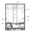
- a refrigerator temperature sensor 59 is provided for detecting the temperature of the refrigerator compartment 14 and controlling the damper portion 39 for the refrigerator compartment.
- a partial chamber temperature sensor 60 for detecting the temperature of the partial chamber 21 and controlling the partial chamber damper section 40 is provided at the opposite diagonal portion across the refrigerator compartment temperature sensor 59 and the refrigerator compartment duct 28. Yes.
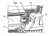
- a deodorizing unit 61 disposed in the detachable unit is detachably provided.
- the deodorizing unit 61, the refrigerator temperature sensor 59, and the partial chamber temperature sensor 60 are all provided in a part of the duct cover 28b that constitutes the refrigerator return duct 58, and the mounting portion 28bb (the refrigerator temperature sensor 59 and the refrigerator compartment temperature sensor 59).
- a mounting portion for the partial chamber temperature sensor 60 is attached and integrated (not shown) (see FIGS. 19 to 23).
- FIG. 14B is a cross-sectional view taken along a horizontal direction of a portion A (refrigeration chamber damper portion) in the refrigerating chamber duct 28 of FIG. 14A of the refrigerator according to the embodiment of the present disclosure; Sectional drawing cut
- the W / D (hereinafter referred to as the aspect ratio) represented by the ratio of the long side W to the short side D of the cross section in the horizontal direction of the duct member 28a in the refrigerator compartment duct 28.
- a part aspect ratio W1 / D1
- B part aspect ratio W2 / D2
- C part aspect ratio W3 / D3.
- a part aspect ratio ⁇ B part aspect ratio ⁇ C part aspect ratio have.
- FIG. 14C is a cross-sectional view cut in the horizontal direction of the refrigerator compartment duct of the refrigerator according to the embodiment of the present disclosure.
- FIG. 14D is a diagram for describing a discharge port of the refrigerator compartment duct of the refrigerator according to the embodiment of the present disclosure.
- the duct cover 28b covering the surface of the duct member 28a on the refrigerator compartment 14 side is provided with extending ribs 28c on both the left and right sides of the duct cover 28b.
- the extending rib 28c extends from the duct cover 28b to the left and right and is integrally formed with the duct cover 28b. Note that the extending rib 28c does not necessarily have to be integrally formed with the duct cover 28b, but may be formed as a separate part and attached to the duct cover 28b.
- the extending rib 28c has an inclined surface that is inclined to the back side (the back side of the refrigerator 90), and the end portion extends further to the back side with a larger angle (that is, The angle of the duct cover 28b that is bent from the surface on the refrigerator compartment 14 side to the back side is further increased).
- the extension rib 28c is provided to extend from the duct cover 28b to the left and right so that the side discharge port 28d provided in the duct member 28a is not directly visible when the user views the refrigerator compartment 14 from the front. .
- the lower surface of the side discharge port 28d has an inclined surface (an inclined surface inclined so that the cold air flows upward) with respect to the flow of the cold air.
- FIG. 24 is a perspective view of the cooling chamber from which the cooler of the refrigerator according to the embodiment of the present disclosure is removed as viewed from the back side.
- FIG. 25 is a plan view of the cooling chamber from which the cooler of the refrigerator according to the embodiment of the present disclosure is removed as viewed from the back side.
- FIG. 26 is a plan view illustrating a back plate of the freezer compartment of the refrigerator according to the embodiment of the present disclosure.
- FIG. 27 is an exploded perspective view of the cooling chamber components of the refrigerator according to the embodiment of the present disclosure.
- FIG. 28 is a perspective view of the cooling chamber of the refrigerator according to the embodiment of the present disclosure as viewed obliquely from the upper front.
- FIG. 29 is an enlarged cross-sectional view illustrating a main part of the cooling chamber of the refrigerator according to the embodiment of the present disclosure.
- FIG. 30 is an enlarged cross-sectional view of another example illustrating the main part of the cooling chamber of the refrigerator according to the embodiment of the present disclosure.
- FIG. 31A is a perspective view illustrating the freezer damper of the refrigerator according to the embodiment of the present disclosure.
- FIG. 31B is a cross-sectional view of the freezer compartment damper according to the embodiment of the present disclosure.
- the freezer compartment 18 is disposed below the refrigerator compartment 14 and in front of the cooling compartment 23.
- a freezer compartment 62 is provided so that it can be freely put in and out by opening and closing the door 11.
- the freezer compartment 62 includes a lower container 62a and an upper container 62b placed above the lower container 62a.
- the freezer compartment back plate 32 is disposed between the freezer compartment 18 and the cooling chamber 23, and between the freezer compartment back plate 32 and the cooling chamber forming plate 31, the cooling fan 25 downstream side of the cooling compartment 23.
- a freezer compartment duct 29 is formed in communication (see FIG. 6).
- the freezer compartment back plate 32 is provided with a cold air outlet 63 across a plurality of upper and lower stages as shown in FIG.
- the uppermost cold air outlet 63 supplies cold air to the ice making chamber 16 and the switching chamber 15, and the middle cold air outlet 63 supplies cold air to the upper container 62 b of the freezer compartment 62, and the lowermost cold air outlet 63 is configured to supply cold air to the lower container 62a.
- the freezer compartment 18 is provided with a freezer cold air return port 64 communicating with the lower portion of the cooler chamber 23 at the lower portion of the freezer rear plate (partition plate) 32.
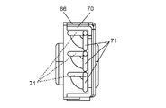
- the refrigerated cold air return port 64 is composed of a freezer compartment side frame portion 65 and a cooling compartment side mouth frame portion 66.
- the freezer compartment side rim portion 65 and the cooling compartment side rim portion 66 are inclined further toward the rear, that is, toward the cooling chamber 23 as they approach the upper end.
- the freezing cold air return port 64 is provided with a grill 67 on the freezing chamber side opening frame portion 65, and a freezing chamber damper 68 is provided on the cooling chamber side opening frame portion 66.
- the grill 67 provided in the freezer compartment side frame portion 65 rectifies the cold air flowing from the freezer compartment 18 to the cooling chamber 23, and each of the plurality of grill pieces 69 of the grill 67 has an end portion on the cooling compartment side, It inclines so that it may be located upwards from the freezer compartment side edge part.
- the grill piece 69 of the grill 67 is configured so that the front and rear lengths of the grill piece 69 positioned downward are longer and are arranged along the rear surface of the freezer compartment container 62 in the freezer compartment 18. ing.
- the freezer compartment damper 68 provided in the cooling room side opening frame portion 66 controls opening and closing of the cold air supplied to the freezer compartment 18.
- the freezer compartment damper 68 is formed of a similar heat resistant resin on a damper frame (frame body) 70 formed of a heat resistant resin, for example, polyphenylene sulfide resin (PPS resin).
- a plurality of flaps 71 are provided in the freezer compartment damper 68.
- the cooling chamber side end of each of the plurality of flaps 71 is pivotally supported by the damper frame body 70, and as shown in FIG.
- the flap 71 is provided on the cooling chamber 23 side opposite to the freezer compartment 18. Is configured to open. Further, the freezer damper 68 is configured to be driven by a freezing damper driving motor unit 72 fixed to one end of the damper frame 70. In FIG. 31B, a solid lead line indicates when the flap 71 is closed, and a broken lead line indicates when the flap 71 is open.
- the freezer compartment damper 68 includes a damper frame body 70 in a state in which the freezer damper driving motor unit 72 is fixed to a claw piece 73 provided in the cooling chamber side opening frame portion 66. By engaging (ballistic engagement), the freezer compartment back plate 32 is attached and unitized.
- the freezer compartment damper 68 is provided so as to be inclined along the inclination of the cooling chamber side opening frame portion 66 so that the cooling chamber side of the freezer compartment damper 68 is located below the freezer compartment side. That is, the damper frame of the freezer compartment damper 68 so that the cooling chamber side (end portion) of each of the damper frame 70 and the flap 71 of the freezer compartment damper 68 is located below the freezer compartment side (end portion).
- the body 70 and the flap 71 are provided to be inclined toward the cooling chamber 23 with reference to a vertical plane parallel to the front surface or the back surface of the refrigerator 90 (see FIG. 29).
- the freezer compartment damper 68 is provided so that the cold air flowing to the cooling chamber 23 along each of the plurality of flaps 71 flows to the lower edge of the cooler 24.
- the freezer compartment damper 68 has an upper portion (an upper piece portion of the damper frame 70) positioned above the lower end edge of the cooler 24 and a lower portion (damper frame body). 70 (lower side portion) is provided below the lower end of the cooler 24. With such a configuration, the cool air flows from the lower end edge of the cooler 24 to the lower part.
- the freezer compartment damper 68 is provided such that the lower portion (the lower side portion of the damper frame 70) is located above the glass tube heater 26 (FIG. 24). Moreover, the freezer compartment damper 68 is set so that the hot and cold air heated by the glass tube heater 26 is surely touched during defrosting.
- the lower side 66a (FIG. 29) of the cooling chamber side frame portion 66 that supports the freezer compartment damper 68 has a double wall, and the lower surface of the lower side 66a projects into the cooling chamber 23 in an arc shape. It is formed in a shape (a shape protruding from the bottom surface 23a of the cooling chamber 23 toward the glass tube heater 26).
- the cooling chamber side frame portion 66 is configured to prevent the radiant heat from the glass tube heater 26 from directly irradiating the freezing chamber damper 68.
- the gap portion 66b of the double wall portion of the lower side 66a of the cooling chamber side opening frame portion 66 is opened facing the freezer compartment 18 and is cooled by the freezer compartment cold air. It is configured so that an excessive temperature rise is suppressed by the radiant heat from.
- the freezer damper 68 is configured so that the freezing damper driving motor unit 72 is disposed from the heater portion 26 a so as not to face the heater portion 26 a of the glass tube heater 26 in the longitudinal direction of the glass tube heater 26. It is arranged so that it is located in a place shifted outward.
- the refrigeration damper driving motor unit 72 is located on the refrigerator compartment return duct 58 side beside the cooling chamber 23. By disposing at this position, the refrigeration damper driving motor unit 72 is positioned outside the heater portion 26 a, and the plurality of flaps 71 of the freezer compartment damper 68 are located on the left and right sides of the cooler 24. It arrange
- the freezer compartment damper 68 is provided only in the freezer cold air return port 64, and no damper is provided in the cold air discharge passage from the cooling chamber 23 to the cold air outlet 63.
- the freezer compartment 18 is kept in communication.
- the vegetable compartment 17 is arrange
- the vegetable room duct 30 for supplying cold air to the vegetable room 17 is arranged on the front side of the refrigeration room return duct 58 next to the cooling room 23 (adjacent in the front-rear direction). Yes.
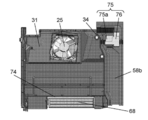
- the upper part of the vegetable compartment duct 30 is connected to the 2nd cold air supply port 34 provided in the cooling chamber 23, as shown in FIG.4 and FIG.10.
- the second cold air supply port 34 is formed independently of the first cold air supply port 33 serving as the cold air supply port to the refrigerator compartment 14 (see FIG. 10). That is, the second cold air supply port 34 is provided below the partition plate 5 that partitions the refrigerator compartment 14 located above the cooling chamber 23 and the freezer compartment 18. More specifically, the second cold air supply port 34 is provided in the rear projection surface of the freezer compartment 18 and at the downstream side portion of the cooling fan 25 substantially the same height as the cooling fan 25. .
- the lower end of the vegetable compartment duct 30 connected to the second cold air supply port 34 opens to the upper portion of the vegetable compartment 17 and is configured to supply cold air to the vegetable compartment 17.
- the vegetable compartment duct 30 has an opening 74 on the side of its upper end, and the opening 74 and the second cold air supply port 34 are abutted and connected.
- a vegetable room damper 75 is incorporated in the vicinity of the connection portion between the vegetable room duct 30 and the second cold air supply port 34, specifically, at substantially the same height as the cooling fan 25 (the height range of the cooling fan 25). ing.
- the vegetable compartment damper 75 is fitted into a concave groove 58b which becomes a vegetable compartment duct passage portion formed on the front surface of the refrigerator compartment return duct 58.
- the vegetable compartment damper 75 is placed between the refrigerator compartment return duct 58 and the vegetable compartment duct 30. It is pinched and fixed.
- the vegetable compartment duct 30 and the refrigeration compartment return duct 58 are formed of a material having elastic force such as styrofoam. The elastic force ensures airtightness between the two, and at the same time, the airtightness of the vegetable compartment damper 75. Is also secured.
- the vegetable compartment damper 75 has a vegetable damper driving motor unit 76 and a damper piece 75a driven by the vegetable damper driving motor unit 76.
- the vegetable compartment damper 75 is configured such that the damper piece 75a opens in the direction opposite to the flow of the cold air flowing through the vegetable compartment duct 30 (upward in the present embodiment).
- the direction in which the damper piece 75a of the vegetable compartment damper 75 opens is opposite to the direction in which the damper opening of the refrigerator compartment duct 28 opens.
- the cold air after cooling the vegetable compartment 17 returns to the cooling compartment 23 through a vegetable compartment return duct (not shown) provided on the ceiling surface of the vegetable compartment 17 (see FIG. 3).
- the compressor 27 and the cooling fan 25 are driven, and the cold air generated by the cooler 24 is sent to the downstream side of the cooling fan 25. Supply (see FIGS. 2 to 4).
- the cold air supplied to the downstream side of the cooling fan 25 passes through the cold room damper 37 from the first cold air supply port 33 that opens to the upper surface of the cooling chamber 23 on the downstream side of the cooling fan 25, and passes through the cold room damper 37. 28, and is blown out into the refrigerator compartment 14 from the cold air outlets (not shown) opened on the left and right side surfaces of the refrigerator compartment duct 28 to cool the inside of the refrigerator compartment 14 (see FIG. 4).
- the cold air supplied to the downstream side of the cooling fan 25 is also supplied to the vegetable compartment duct 30 through the vegetable compartment damper 75 from the second cold air supply port 34 opened on the upper side surface on the downstream side of the cooling fan 25.
- the vegetable compartment 17 is supplied from the lower end opening of the vegetable compartment duct 30 to cool the inside of the vegetable compartment 17.
- the vegetable compartment damper 75 When the temperature of the vegetable compartment 17 set higher than the refrigerator compartment 14 reaches the preset temperature, the vegetable compartment damper 75 is closed, the supply of cold air to the vegetable compartment 17 is stopped, and the vegetable compartment 17 is kept at the preset temperature. Be drunk.
- the second cold air supply port 34 that supplies cold air to the vegetable compartment 17 and the first cold air supply port 33 that supplies cold air to the refrigerating chamber 14 include the cooling chamber 23.
- the cooling chamber 23 are separately provided independently, and are configured such that cold air is independently supplied directly from the cooling chamber 23 to the vegetable compartment duct 30.
- the cooling of the refrigerator compartment 14 can be performed at the same level as when the cold air is supplied to the vegetable compartment 17, and can be stably performed without being affected by the opening and closing of the vegetable compartment damper 75. .
- the first cold air supply port 33 is provided on the upper surface of the cooling chamber 23 on the downstream side of the cooling fan 25, while the second cold air supply port 34 is provided on the cooling fan 25. It is provided on the side surface of the cooling chamber 23 in the upper part on the downstream side.
- the refrigerator 90 according to the present embodiment opens the refrigerator compartment duct 28 and the vegetable compartment duct 30 on different surfaces of the cooling compartment 23, so that the refrigerator compartment duct 28 and the vegetable compartment duct 30 are separately provided.
- the cooling chamber 23 is configured to open independently.
- the refrigerator 90 is not limited to such a configuration, and the first cold air supply port 33 and the second cold air supply port 34 are formed on the same surface of the cooling chamber 23, for example, the upper surface of the cooling chamber 23 on the downstream side of the cooling fan 25. And may be provided independently of each other. In this case, the first cold air supply port 33 and the second cold air supply port 34 and the first cold air supply port 34 and the first cold air supply port 33 and the first cold air supply port 33 and the second cold air supply port 34 are not affected by the opening / closing of the refrigerator compartment damper 37 or the vegetable compartment damper 75. Two cold air supply ports 34 may be provided apart from each other.
- the vegetable compartment duct 30 is directly connected to the downstream side of the cooling fan 25 of the cooling chamber 23 and is connected to the cooling chamber 23 in the rear projection plane of the freezer compartment 18 located in front of the cooling chamber 23.
- the vegetable compartment duct 30 is connected to the cooling chamber 23 at a position lower than the top surface of the freezer compartment 18 and above the bottom surface of the freezer compartment 10.
- the cooling performance can be improved by at least the amount of the cool air circulation increased.
- the vegetable compartment damper 75 has a height that overlaps the cooling fan 25 of the cooling chamber 23 (so that at least a part of each of the cooling fan 25 and the vegetable compartment damper 75 is located at the same height in the vertical direction). Therefore, the reliability of the refrigerator can be ensured by preventing malfunctions while utilizing the effect of improving the cooling performance.
- the vegetable compartment 17 is set to a relatively high temperature and has a high humidity. For this reason, when the vegetable compartment damper 75 is closed and the cold air circulation is stopped, the hot and cold air with high humidity may flow backward from the vegetable compartment 17 into the vegetable compartment duct 30.
- hot and cold air with high humidity touches the vegetable room damper 75, the moisture is condensed, and when the vegetable room 17 resumes cooling, the condensed water is frozen by the cold air supplied to the vegetable room 17, and the vegetable room damper 75 opens and closes. It may become defective.
- the vegetable compartment damper 75 is provided at a height that overlaps the cooling fan 25. With such a configuration, a distance from the vegetable compartment 17 to the vegetable compartment damper 75 can be secured, and the vegetable compartment damper 75 can be separated upward from the vegetable compartment 17 by the height dimension of the cooler 24. . Thereby, when the cold air circulation is stopped, it is possible to prevent the hot and cold air with high humidity in the vegetable compartment 17 from rising into the vegetable compartment duct 30 and reaching the vegetable compartment damper 75, and the vegetable compartment damper 75 being condensed.
- the vegetable compartment duct 30 is connected to the cooling compartment 23 in the rear projection plane of the freezing compartment 18 located in front of the cooling compartment 23, and the vegetable compartment damper 75 is By being incorporated in the vegetable compartment duct 30 at a height that overlaps with the cooling fan 25 (see FIGS. 7 and 8), the cooling performance is improved while the malfunction of the vegetable compartment damper 75 is suppressed, and the reliability of the refrigerator is improved. Sex can be secured.
- the vegetable compartment damper 75 is provided in the vegetable compartment duct 30, it is a partition plate which partitions the space between the refrigerator compartment 14 and the freezer compartment 18 in a place different from the vegetable compartment duct 30, for example, as in the past. 5, the vegetable room damper 75 can be easily incorporated as compared with a case where a vegetable room damper is separately incorporated. Therefore, with such a configuration, productivity can be significantly improved.
- the vegetable compartment damper 75 of the refrigerator 90 of the present embodiment can be separately incorporated into the vegetable compartment duct 30 outside the refrigerator body 1. Therefore, the vegetable compartment damper 75 can be incorporated into the refrigerator main body 1 only by incorporating the vegetable compartment duct 30 in which the vegetable compartment damper 75 is incorporated beside the cooling chamber 23. Thereby, the incorporation into the refrigerator main body 1 of the vegetable compartment damper 75 becomes easy.
- the vegetable compartment damper 75 can be attached and detached together with the vegetable compartment duct 30 simply by attaching and detaching the freezer compartment back plate 32 (see FIGS. 6 and 8) on the front side of the cooling compartment 23, which facilitates maintenance and convenience. Can also be improved.
- the vegetable compartment duct 30 is superposed on the refrigerator compartment return duct 58 from the refrigerator compartment 14 to the refrigerator compartment 23 (adjacent to each other in the front-rear direction of the refrigerator 90). Are arranged).
- the vegetable compartment duct 30 and the refrigerated compartment return duct 58 are each formed of an elastic material such as polystyrene foam.
- the vegetable compartment damper 75 is sandwiched between the vegetable compartment duct 30 and the refrigerator compartment return duct 58. With such a configuration, productivity can be further improved.
- the vegetable room damper 75 is sandwiched between the vegetable room duct 30 and the refrigeration room return duct 58, first, outside the refrigerator body 1, between the vegetable room duct 30 and the refrigeration room return duct 58, The vegetable room damper 75 is incorporated.
- the vegetable room duct 30, the refrigeration room return duct 58, and the vegetable room damper 75 can be simply assembled by installing a set of the vegetable room duct 30 and the refrigeration room return duct 58 next to the cooling room 23. It can be incorporated into the refrigerator body 1. Thereby, productivity can be improved.
- the vegetable compartment duct 30 and the refrigeration compartment return duct 58 are both made of a material such as polystyrene foam and have an elastic force.
- the vegetable compartment damper 75 can be incorporated in the refrigerator main body 1 in an airtight state without using a seal member or the like by the elastic force of the vegetable compartment duct 30 and the refrigerator compartment return duct 58. Therefore, there is no need to use a separate sealing member for ensuring airtightness as in the case of incorporating a conventional vegetable compartment damper into the partition plate, and the configuration can be simplified and the process can be shortened, further improving productivity. Can be realized.
- the vegetable compartment damper 75 is elastically supported by the vegetable compartment duct 30 and the refrigerator compartment return duct 58. With such a configuration, it is possible to suppress the generation of noise due to micro-vibration that tends to occur during an opening / closing operation or the like, and it is possible to provide a refrigerator with high quietness.
- the refrigerator compartment 14 is cooled by supplying cold air through the refrigerator compartment duct 28 (see FIG. 4). At this time, a part of the cold air supplied to the refrigerator compartment duct 28 is also supplied to the partial chamber 21 and the chilled chamber 22 provided in the lower part of the refrigerator compartment 14, and the partial chamber 21 and the chilled chamber 22 are also cooled (FIG. 3).
- the cooling of the refrigerating room 14 is controlled by opening and closing the refrigerating room damper unit 39 (see FIG. 8) that operates based on the output from the refrigerating room temperature sensor 59 (see FIG. 16), and is maintained at the set temperature.
- the chilled chamber 22, together with the refrigerated chamber 14, is controlled by the opening and closing of the refrigerated chamber damper 39, and the chilled chamber 22 is lower than the refrigerated chamber 14 by the cold radiation from the partial chamber 21 located below the chilled chamber 22. Maintained at a temperature of
- the chilled chamber 22 may be in a state where the cold radiation from the partial chamber 21 is strong and falls below the set temperature, that is, it is too cold.
- a chilled chamber temperature sensor (not shown).
- the temperature adjusting heater 49 (see FIG. 14A) laid on the bottom of the chilled chamber 22 generates heat based on the output from the chilled chamber 22, and the chilled chamber 22 is maintained at the set temperature.
- the indoor cooling is controlled and maintained at the set temperature by opening and closing the partial chamber damper 40 (see FIG. 8) that operates based on the output from the partial chamber temperature sensor 60 (see FIG. 16).
- the refrigerator 90 can control the cooling of the chilled chamber 22 and the partial chamber 21 provided in the lower part of the refrigerator compartment 14 in different temperature zones, thereby improving usability. .
- the refrigerator 90 of the present embodiment even if the vegetable compartment damper 75 is opened and closed to control the cooling of the vegetable compartment 17, the amount of cold air supplied to the refrigerator compartment 14 does not change, Since a constant and stable amount of cool air is supplied to the refrigerator compartment 14, the temperature accuracy of the chilled chamber 22 and the partial chamber 21 that require high control accuracy can be increased as desired. The preservation quality of the ingredients at can be improved.
- W represented by the ratio of the long side W and the short side D of the duct member 28a in the refrigerator compartment duct 28.
- ribs 28c that extend left and right and are integrally formed with the duct cover 28b (FIG. 14C). reference).
- the lower surface of the side discharge port 28d has an inclined surface that directs the flow of cold air upward.
- the cold air that has cooled the refrigerator compartment 14 is first supplied to the cold air return port (chilled side) 45 at the rear of the ceiling surface of the chilled chamber 22, the opening 48 below the chilled chamber door / handle portion 47, and the chilled chamber. It flows to the cold air return passage portion (chilled side) 46 behind the chilled chamber 22 through a gap with the outer peripheral portion of the container 44 (see FIG. 14A).
- the cold air flowing to the cold air return passage portion (chilled side) 46 at the rear of the chilled chamber 22 flows from the cold air return port (partial side) 55 provided in the ceiling plate member 50 of the partial chamber 21 to the cold air return passage behind the partial chamber 21.
- the cold air that has flowed to the cold air return passage portion (partial side) 56 behind the partial chamber 21 is cooled through the cold chamber return duct 58 from the cold air confluence return port 57 provided in the partition plate 5 serving as the bottom surface of the partial chamber 21. Return to chamber 23.
- the cold air that has cooled the chilled chamber 22 overflows from the chilled chamber container 44, and merges with the cold air from the refrigerator compartment 14 in the cold air return passage portion (chilled side) 46 in the chilled chamber 22.
- the cold air in the partial chamber 21 overflows from the partial chamber container 52, flows to the cold air return passage portion (partial side) 56 behind the partial chamber 21, and merges with the cold air from the refrigerator compartment 14 and the chilled chamber 22.
- the cooling air return port 57 returns to the cooling chamber 23 via the refrigerator return duct 58.
- the refrigerator 90 of the present embodiment includes the cold air return port (chilled side) 45, the cold air return passage portion (chilled side) 46 provided behind the chilled chamber 22 in the refrigerator compartment 14, and the cold air return.
- the cold air in the partial chamber 21 can be returned to the cooling chamber 23. Therefore, it is not necessary to separately provide a duct portion for returning the cool air of each chamber (the chilled chamber 22 and the partial chamber 21) to the cooling chamber 23 in the refrigerator compartment 14 along the refrigerator compartment duct 28. Therefore, the internal volume of the refrigerator compartment 14 can be increased as much as it is not necessary to provide a separate duct, and more food can be stored in a cold state.
- the main flow of cold air in the cold air return passage portion (partial side) 56 that flows from the refrigerator compartment 14 to the cold air merge return port 57 via the chilled chamber 22 is returned to the cold air return port (partial side) 55 and the cold air merge return. It is on the line connecting the mouth 57.
- This cold air includes cold air from the chilled chamber 22 and cold air from the partial chamber 21, most of which is cold air from the refrigerator compartment 14.
- a refrigerator temperature sensor 59 (see FIGS. 16 and 17) is provided between a cold air return port (partial side) 55 through which mainstream cold air flows and a cold air merging return port 57. Therefore, the temperature of the refrigerator compartment 14 can be detected accurately. Therefore, the temperature of the refrigerator compartment 14 can be accurately controlled to the set temperature.
- the partial chamber temperature sensor (cold chamber temperature sensor) 60 includes a cold air return port (partial side) 55 in which the cold air flow in the cold air return passage portion (partial side) 56 in the partial chamber 21 is mainstream, and a cold air confluence return port.
- the refrigerator temperature sensor 59 when viewed from the front, is in the left-right direction across the refrigerator compartment duct 28. In the opposite diagonal portion.
- the temperature of the partial chamber 21 can also be accurately detected and controlled with high accuracy. That is, the diagonal part opposite to the cold room temperature sensor 59 across the cold room duct 28 has little cold in the cold room 14, and most of the cold air flowing through this part is the cold air in the partial chamber 21. In this part, the cold in the partial chamber 21 is drifting. Therefore, with such a configuration, the temperature in the partial chamber 21 can be accurately detected, and highly accurate temperature control can be performed.
- the chilled chamber 22 is cooled to a temperature lower than the refrigerating chamber temperature by receiving the cold radiation from the partial chamber 21, but when the cooling temperature of the partial chamber 21 is changed, the influence thereof is reduced. In response, the temperature of the chilled chamber 22 tends to change.
- the temperature adjusting heater 49 on the bottom surface of the chilled chamber 22 can be turned on / off to control the set temperature. Temperature control can also be performed with high accuracy.
- the temperature control of the chilled chamber 22 can be performed by supplying a cooler to the chilled chamber 22 by providing a damper and opening and closing the damper in the same manner as the refrigerator chamber 14 and the partial chamber 21. Therefore, the refrigerator compartment volume is reduced, or the refrigerator is enlarged.
- the heater system is used as in the present embodiment, it is possible to control the temperature of the chilled chamber 22 without requiring a space and a passage structure for providing a damper and easily and without reducing the volume of the refrigerator compartment. .
- the refrigerator compartment temperature sensor 59 and the partial compartment temperature sensor 60 are attached to the duct cover 28b of the refrigerator compartment duct 28, they can be incorporated at predetermined positions by mounting the duct cover 28b in the refrigerator compartment. Therefore, compared with the case where the duct cover 28b and each sensor (refrigeration room temperature sensor 59 and partial room temperature sensor 60) are incorporated separately, the workability is greatly improved and the productivity can be increased.
- the deodorizing unit 61 in the refrigerator 90 of the present embodiment, since the deodorizing unit 61 is attached to the duct cover 28b, the deodorizing unit 61 can be easily incorporated, and the productivity is further improved. Can be improved. Furthermore, by providing the deodorizing unit 61, it is possible to remove the odor in the cold air transferred from the food in the refrigerator compartment 14, and a sanitary refrigerator can be obtained.
- the cold air return port (chilled side) 45 (see FIG. 15) and the cold air return port (partial side) 55 and the cold air merging return port 57 constituting the cold air return passage in the refrigerator compartment 14 are connected to the front of the refrigerator 90.
- the positions are shifted in the left-right direction when viewed from the side. Therefore, even if debris such as food is dropped from the cold air return port (chilled side) 45 or the cold air return port (partial side) 55 through the cold air return port (chilled side) 45, this is the cold air confluence. It can prevent falling on the return port 57 and clogging the cold air merging return port 57 or reducing the opening area of the cold air merging return port 57, and can maintain good cold air return performance over a long period of time. .
- the cold air from the downstream side of the cooling fan 25 is supplied from the cold air outlet 63 of the freezer compartment back plate 32 and cooled.
- the cold air from the uppermost left air outlet 63 is supplied to the ice making chamber 16, and the cold air from the uppermost right air outlet 63 is supplied to the switching chamber 15 to cool each chamber.
- the cool air that has cooled the freezer compartment 18, the ice making chamber 16, and the switching chamber 15 returns to the cooler chamber 23 from the freezer cold air return port 64 provided at the lower portion of the freezer compartment 18.
- the freezer cold air return port 64 of the freezer compartment 18 is provided with the freezer compartment damper 68, it is supplied to the freezer compartment 18.
- the amount of cold air to be controlled can be controlled by opening and closing the freezer damper 68. Therefore, although the freezer compartment 18 is at the set temperature, the temperature of the refrigerator compartment 14 is high, the compressor 27 and the cooling fan 25 are driven, and the cold air is supplied to the freezer compartment 18 and is excessively cooled. Can be prevented, and good frozen storage can be realized.
- the freezer compartment damper 68 is provided not on the cold air outlet 63 side of the freezer compartment 18 but on the freezer cold air return port 64 side below the freezer compartment 18, thus simplifying the configuration.
- a stable damper operation can be obtained, the temperature control accuracy of the freezer compartment 18 can be improved, and the reliability can be increased.
- the freezer compartment 18 is provided adjacent to the front surface of the cooling chamber 23 (see FIG. 6), and the cold air outlet 63 provided in the upper portion of the freezer compartment 18 is connected to the downstream side of the cooling fan 25 of the cooling chamber 23. It communicates (see FIG. 5).
- the high-humidity warm air after defrosting moves up the cooling chamber 23 by the draft and reaches the cold air outlet 63.
- the freezer compartment damper 68 is provided on the cold air outlet 63 side, the hot and cold air at high temperature and high humidity will contact the freezer compartment damper 68 to form dew and freeze when the cooling operation is resumed after the completion of the defrosting operation. There is a risk of it happening.
- the refrigerator 90 of the present embodiment by providing the freezer cooler 68 at the freezer cold air return port 64 below the cooler chamber 23, most of the high-humidity warm air generated during defrosting is a draft. Therefore, the warm and cool air that comes into contact with the freezer compartment damper 68 is very small and has a low humidity, and the ice formed by condensation is also minimal. Therefore, the operation of the freezer damper 68 can be performed stably.
- icing can be prevented by residual heat from the glass tube heater 26 for defrosting. With such a configuration, a heater for exclusive use of defrosting or the like is not required, and the configuration can be simplified. That is, it is possible to improve the temperature control accuracy and at the same time improve the reliability.
- the freezer compartment damper 68 is configured by a combination of a plurality of flaps 71. Therefore, the front-rear width dimension when each of the plurality of flaps 71 is opened is one sheet. Compared with the front-rear width dimension of the damper constituted by the flap, it can be significantly reduced. Therefore, the freezer compartment damper 68 itself can be made compact, and at the same time, the space for installing the freezer compartment damper 68 can be greatly reduced, and the volume in the freezer compartment 18 can be increased accordingly.
- each of the plurality of flaps 71 of the freezer compartment damper 68 is provided so as to open toward the cooling chamber 23 side. Also with such a configuration, the volume in the freezer compartment 18 can be increased. That is, when the freezer compartment damper 68 is configured such that each of the plurality of flaps 71 opens toward the freezer compartment 18 side, each of the plurality of flaps 71 protrudes toward the freezer compartment 18 side. Therefore, the freezer compartment container 62 must be positioned forward, and the volume of the freezer compartment container 62, that is, the volume of the freezer compartment 18 must be reduced. However, such a configuration as the refrigerator 90 of the present embodiment can eliminate such a situation and increase the volume of the freezer compartment 18.
- the cooling chamber side frame portion 66 of the refrigerated cold air return port 64 to which the freezing chamber damper 68 is attached is positioned rearward, that is, on the cooling chamber 23 side as it goes upward with respect to the vertical line. That is, the end of the freezer compartment damper 68 mounted on the cooling chamber side opening frame portion 66 on the side of the cooling chamber 23 is inclined below the end of the freezer compartment 18 side. Is provided.
- the freezer compartment damper 68 is closed, and it is comprised so that the warm air in the cooling chamber 23 may not enter into the freezer compartment 18.
- the freezer compartment damper 68 is provided close to the glass tube heater 26 below the cooling chamber 23, so that the temperature rises during the defrosting operation.
- the damper frame 70 and the plurality of flaps 71 and the like constituting the freezer damper 68 are formed of a heat-resistant material, thermal deformation and the like can be prevented, and the damper operation and the good operation over a long period of time can be prevented. The action can be secured.
- the freezer compartment damper 68 is provided such that the lower portion (the lower side portion of the damper frame 70) is positioned not above the glass tube heater 26 but above it. Therefore, it becomes the form which leaves
- the warm and cool air heated by the glass tube heater 26 reliably touches the freezer damper 68, and even if the freezer damper 68 is frosted, the damper is reliably defrosted. Operation is good.
- the lower side 66a of the cooling chamber side opening frame 66 that supports the lower portion of the freezer damper 68 that has a short distance from the glass tube heater 26 protrudes into the cooling chamber 23 (the glass tube heater from the bottom surface 23a of the cooling chamber 23). 26 (see FIG. 29).
- the lower side 66 a of the cooling chamber side opening frame portion 66 is formed of a double wall, and the gap portion 66 b of the double wall has a shape that opens toward the freezer compartment 18.
- the direct heat influence by irradiation of the radiant heat ray from the glass tube heater 26 is provided with a heat shield plate 77 on the heater cover 35 above the glass tube heater 26, or the heater cover 35.
- the freezer compartment damper 68 is located at a position where the motor unit 72 for driving the freezer damper does not face the heater portion 26a of the glass tube heater 26, for example, in the present embodiment, refrigeration beside the cooling compartment 23. Since it is provided on the side of the room return duct 58 and the vegetable room duct 30 (see FIG. 7), the direct thermal effect of the radiant heat radiation from the glass tube heater 26 on the motor unit 72 for driving the refrigeration damper can be reduced. Can do. Thereby, the extreme temperature rise of the refrigeration damper driving motor unit 72, which includes a plurality of gears and the like and is a precision component, can be prevented, and a stable damper operation can be ensured.
- the freezing chamber damper 68 has the refrigeration damper driving motor unit 72 positioned beside the cooling chamber 23. It arrange
- the plurality of flaps 71 that open and close the cool air flow path are positioned closer to the center line of the cooler 24, and the cool air returning to the cooling chamber 23 is efficiently contacted with the cooler 24. Will be able to. Thereby, the cooler 24 can fully exhibit the original cooling performance of the cooler 24 itself, and can greatly improve the cooling performance.
- the freezer compartment damper 68 has an upper portion (an upper piece portion of the damper frame 70) located above the lower end edge of the cooler 24 and a lower portion (the damper frame 70).
- the lower side 66a portion) is provided below the lower end of the cooler 24.
- the freezer damper 68 is unitized by elastically engaging with the cooling chamber side opening frame 66 provided on the freezer back plate 32 (see FIGS. 29, 31A and 31B). With such a configuration, the freezer compartment damper 68 can be easily incorporated into the freezer compartment 18 by mounting the freezer compartment back plate 32, and productivity can be improved.
- a grill 67 is attached to the freezing / cooling air return port 64 on the freezing chamber 18 side of the freezing chamber damper 68.
- the grill 67 has a plurality of grill pieces 69.
- the grill 67 is provided so as to be inclined so that the cooling chamber side end portion of each grill piece 69 is positioned above the refrigeration chamber side end portion.
- the plurality of grill pieces 69 of the grill 67 are formed such that the front and rear lengths of the lower grill pieces 69 are longer, and have a shape along the rear surface of the freezer compartment container 62 in the freezer compartment 18. With such a configuration, the flow of cool air in the freezer compartment 18 can be made smooth, and the cooling performance can be improved.
- the refrigerator 90 is provided in the refrigerator main body 1 in which the refrigerator compartment 14, the freezer compartment 18 and the vegetable compartment 17 are disposed, and behind the refrigerator compartment 18. 18 and the vegetable compartment 17, respectively, a cooling chamber 23 for generating cold air to be supplied, a refrigerator compartment duct for guiding the cold air from the cooling compartment 23 to the refrigerator compartment, and the cold air from the cooling compartment 23 is guided to the vegetable compartment 17.
- a vegetable compartment duct 30 is provided.
- the refrigerator compartment duct 28 is provided with a refrigerator compartment damper 37
- the vegetable compartment duct 30 is provided with a vegetable compartment damper 75.
- the refrigerator 90 of the present embodiment is configured such that the amount of cold air supplied to the refrigerator compartment 14 and the vegetable compartment 17 can be controlled by opening and closing each damper (the refrigerator compartment damper 37 and the vegetable compartment damper 75).
- the refrigerator compartment duct 28 provided with the refrigerator compartment damper 37 and the vegetable compartment duct 30 provided with the vegetable compartment damper 75 are separately made independent of each other at different positions with respect to the cooling chamber 23. It is connected to the chamber 23.
- the cold air from the cooling chamber 23 is supplied to the refrigerator compartment duct 28 and the vegetable compartment duct 30 in an independent manner.
- the amount of cold air supplied to the refrigerator compartment duct 28 is not affected by the opening and closing, and the amount of cold air supplied to the refrigerator compartment 14 is stabilized and the cooling performance is stabilized. Can be improved.
- the vegetable compartment duct 30 may be connected to the cooling chamber 23 within the rear projection plane of the freezing compartment 18 located in front of the cooling compartment 23.
- the vegetable compartment duct 30 does not pass through the partition plate 5 that partitions the refrigerator compartment 14 and the freezer compartment 18 above the cooling compartment 23. Therefore, with such a configuration, the length of the vegetable compartment duct 30 can be shortened and the passage resistance can be reduced. Thereby, the amount of cold air circulation can be increased and the cooling performance can be improved.
- the refrigerator 90 is configured such that the vegetable compartment damper 75 is incorporated in the vegetable compartment duct 30 and is located in the rear projection plane of the freezer compartment 18 together with the vegetable compartment duct 30. Good.
- the vegetable room damper 75 can also be incorporated into the refrigerator body 1 simply by installing the vegetable room duct 30 in the refrigerator body 1.
- Productivity can be greatly improved compared with the case where the vegetable compartment damper 75 is separately incorporated in the partition plate 5 which partitions between the freezer compartment 18.
- the vegetable chamber duct 30 is connected to the cooling chamber 23 in the rear projection plane of the freezing chamber 18 located in front of the cooling chamber 23, thereby reducing the length of the vegetable chamber duct 30 and reducing the passage resistance. Therefore, the amount of cold air circulation can be increased and the cooling performance can be improved.
- the cooling chamber 23 has the cooler 24 and the cooling fan 25 located above it, and the vegetable compartment damper 75 is the position of the height which overlaps with the cooling fan 25. May be provided.
- the vegetable compartment duct 30 can be shortened by a length that partitions the space between the refrigerator compartment 14 and the freezer compartment 18 and passes through the partition plate 5 above the cooling compartment 23, thereby reducing passage resistance.
- the cooling performance can be improved by increasing the amount of cool air circulation.
- the distance from the vegetable compartment 17 to the vegetable compartment damper 75 can be ensured by the height of the cooler 24.
- the vegetable compartment duct 30 is arranged so as to overlap the refrigerator compartment return duct 58 from the refrigerator compartment 14 to the refrigerator compartment 23 (adjacent in the front-rear direction of the refrigerator 90). Also good.
- the vegetable compartment duct 30 and the refrigerator compartment return duct 58 may each be formed with the material which has elasticity. With such a configuration, the hermeticity can be ensured by the elastic force of the vegetable compartment duct 30 and the refrigerator compartment return duct 58, and a seal member or the like for securing the airtightness when separately incorporated in the partition plate 5 is required. Therefore, the configuration can be simplified and the productivity can be improved.
- the refrigerator 90 of this Embodiment may be comprised so that the vegetable compartment damper 75 may be clamped with the vegetable compartment duct 30 and the refrigerator compartment return duct 58.
- the vegetable compartment damper 75 can be rationally incorporated into the vegetable compartment duct 30 by using the refrigerator compartment return duct 58.
- the refrigerator 90 according to an example of the embodiment of the present disclosure also provides a refrigerator that can suppress the space around the cooler storage chamber (the cooling chamber 23, the same applies hereinafter) and increase the internal volume efficiency.
- the refrigerator 90 includes a refrigerating chamber 14, a freezing chamber 18, a cooling chamber 23 disposed behind the freezing chamber 18, and the cooling chamber 23 to the refrigerating chamber 14.
- a refrigeration room damper 37 that controls the amount of supplied cold air, and a freezing room damper 68 provided at the freezing cold air return port through which the cold air supplied to the freezing room 18 is returned to the cooling room 23 are provided.
- no damper is provided in the cool air discharge passage supplied from the cooling chamber 23 to the freezing chamber 18, and the cooling chamber 23 and the freezing chamber 18 are kept in communication with each other. It is configured to be.
- the space around the cooler storage chamber can be suppressed without increasing the space of the cool air discharge air passage, and the internal volume efficiency can be increased.
- the freezer compartment damper 68 may be disposed on a partition plate (the freezer compartment back plate 32) that partitions the freezer compartment 18 and the cooling compartment 23. With such a configuration, the space around the cooler storage chamber can be further suppressed, and the internal volumetric efficiency can be increased.
- the freezer compartment damper 68 includes a frame body (damper frame body) 70, a driving device (a motor unit for driving the freezing damper) 72, and a flap 71. It may be. Moreover, the freezer compartment damper 68 may be configured such that the flap 71 is rotated toward the cooling chamber 23 by the drive device 72. With such a configuration, the space around the cooler storage chamber can be further suppressed, and the internal volumetric efficiency can be increased.
- the freezer damper 68 may include a plurality of flaps 71, and the plurality of flaps 71 may be configured to be opened and closed by the driving device 72. With such a configuration, a space related to the operation of the flap 71 can be suppressed, and the internal volume efficiency can be increased.
- the freezer compartment damper 68 has the frame body 70 and the flap 71 inclined toward the cooling chamber 23 side with respect to a vertical plane parallel to the front surface or the back surface of the refrigerator 90. May be provided. With such a configuration, drainage performance such as defrost water adhering to the freezer compartment damper 68 is improved, and the reliability of the freezer compartment damper 68 can be enhanced.
- the refrigerator 90 may further include a refrigeration chamber return duct 58 on the side of the cooler 24 for returning the cold air supplied to the refrigeration chamber 14 to the cooling chamber 23.
- the freezer damper 68 includes the drive device 72 and the flap 71 that are provided side by side, and the drive device 72 is viewed from the front of the refrigerator 90 and the refrigerator return duct. It may be arranged on the 58 side. With such a configuration, the left-right bias of the freezer damper 68 with respect to the cooler 24 can be improved, and the cooling efficiency can be increased.
- the refrigerator 90 may further include a glass tube heater 26 provided below the cooling chamber 23.
- the outer shell (damper frame body 70) of the freezer damper 68 is made of a heat-resistant material that can withstand the heat from the glass tube heater 26.
- the refrigerator 90 may further include a heater cover 35 provided above the glass tube heater 26.
- a part of the heater cover 35 may be interposed between the glass tube heater 26 and the freezer damper 68.
- the present disclosure also provides a refrigerator 90 that is less susceptible to load fluctuations in the refrigerator compartment 14 and can stably maintain the temperature in the low-temperature compartment at a predetermined temperature.
- the refrigerator 90 is disposed behind the freezer compartment 18, the freezer compartment 18, the partition plate 5 that partitions the refrigerator compartment 14 and the freezer compartment 18, and the freezer compartment 18.
- a low temperature chamber (at least one of the chilled chamber 22 and the partial chamber 21, the same shall apply hereinafter), a cold room 14, and a low temperature chamber provided in the cold room 14 at the lower part of the cooling room 23.
- a refrigerator compartment duct 28 for supplying cold air to each is provided.
- the low greenhouse is partitioned by the ceiling plate 43 in the refrigerating chamber 14 and has a container (at least one of the chilled chamber container 44 and the partial chamber container 52) inside, and a temperature lower than that of the refrigerating chamber 14. Maintained in the belt.
- the refrigerator 90 includes a cold air return port (cold air return port 57) (second cold air return port) provided in the partition plate 5 and a cold air return provided in the ceiling plate 43.
- the cool air return passage section (chilled side) 46 is configured so that the cool air returning from the refrigerator compartment 14 to the cooling chamber 23 is supplied from the cool air return port (chilled side) 45 provided in the ceiling plate 43 to the space outside the container in the low temperature chamber and the partition plate. 5 is configured to be returned to the cooling chamber 23 via a cold air return port (cold air merging return port 57) provided in 5.
- the refrigerator 90 includes a cold air return port (chilled side) 45 provided in the ceiling plate 43, and a cold air return port (cold air merging return port 57) provided in the partition plate 5. May be arranged so as to be shifted from each other in the left-right direction as viewed from the front of the refrigerator 90.
- a cold air return port (chilled side) 45 provided in the ceiling plate 43 from the refrigerator compartment 14
- the refrigerator 90 includes a cold room damper 37 that controls supply of cold air to the cold room 14, a cold room temperature sensor 59, and a low temperature room damper that controls supply of cold air to the low temperature room.
- a cold room damper 37 that controls supply of cold air to the cold room 14
- a cold room temperature sensor 59 that controls supply of cold air to the low temperature room.
- a low temperature room damper that controls supply of cold air to the low temperature room.
- Partial chamber damper 40 and a low temperature chamber temperature sensor (partial chamber temperature sensor 60) may be provided.
- the refrigerating room temperature sensor 59 and the low temperature room temperature sensor may be disposed in the refrigerating room duct 28. With such a configuration, the assembly process can be simplified.
- the refrigerating room temperature sensor 59 and the low temperature room temperature sensor may be arranged to face each other in the left-right direction of the refrigerating room duct 28.
- the temperature in the refrigerator compartment 14 is controlled by detecting the return air from the refrigerator compartment 14, so the low temperature chamber temperature sensor is less susceptible to the return air from the refrigerator compartment 14,
- the temperature in the low temperature chamber (partial chamber 21 in this example) can be maintained at a predetermined temperature more stably.
- the present disclosure provides a refrigerator compartment duct while appropriately setting an aspect ratio (long side / short side) represented by a ratio between a long side and a short side in a horizontal section of the air passage of the refrigerator compartment 28.
- the refrigerator which can ensure cooling performance is provided, without impairing the designability of 28.
- the refrigerator 90 includes a freezer compartment 18, a refrigerator compartment 14 arranged at the top of the freezer compartment 18, and a cooling compartment 23 arranged behind the freezer compartment 18.
- the refrigerating room duct 28 and the refrigerating room damper 37 disposed on the back of the refrigerating room 14, and the low temperature room disposed in the lower part of the refrigerating room 14 and maintained in a temperature zone lower than the refrigerating room 14.
- the aspect ratio (long side / short side) represented by the ratio of the long side to the short side in the horizontal cross section of the air path of the refrigerator compartment duct 28 is the refrigerator compartment.
- the damper 37 portion, the low temperature chamber portion, and the refrigerator compartment 14 portion are set so as to increase in order.
- the effective internal volume of the refrigerator 90 can be increased while appropriately setting the aspect ratio of the refrigerator compartment duct 28, and the cooling performance can be ensured without impairing the design of the refrigerator compartment duct 28. .
- the refrigerator compartment duct 28 has a discharge port (side discharge port 28d) on the side surface and a rib (extension rib 28c) that covers the discharge port on the front side portion. May be provided.
- the lower surface of the discharge port may have an inclined surface that is upward with respect to the flow of cold air.
- the present disclosure can stabilize the amount of cold air supplied to the refrigerating room and improve the cooling performance of the refrigerating room regardless of whether the vegetable room damper is opened or closed. It can be widely applied to refrigerators of various types and sizes.
Landscapes
- Engineering & Computer Science (AREA)
- Chemical & Material Sciences (AREA)
- Combustion & Propulsion (AREA)
- Physics & Mathematics (AREA)
- Mechanical Engineering (AREA)
- Thermal Sciences (AREA)
- General Engineering & Computer Science (AREA)
- Cold Air Circulating Systems And Constructional Details In Refrigerators (AREA)
Abstract
Réfrigérateur comportant un conduit (28) de compartiment de réfrigération dans lequel un registre (37) de compartiment de réfrigération est disposé, et un conduit (30) de compartiment à légumes dans lequel un conduit (75) de compartiment à légumes (75) est disposé. Le conduit (28) de compartiment de réfrigération et le conduit (30) de compartiment à légumes sont reliés à un compartiment de refroidissement (23) séparément et indépendamment, dans des positions respectives différentes par rapport au compartiment de refroidissement (23).
Priority Applications (1)
| Application Number | Priority Date | Filing Date | Title |
|---|---|---|---|
| CN201780033004.1A CN109196290B (zh) | 2016-06-01 | 2017-05-29 | 冷藏库 |
Applications Claiming Priority (10)
| Application Number | Priority Date | Filing Date | Title |
|---|---|---|---|
| JP2016109776A JP6670994B2 (ja) | 2016-06-01 | 2016-06-01 | 冷蔵庫 |
| JP2016-109776 | 2016-06-01 | ||
| JP2016-110603 | 2016-06-02 | ||
| JP2016-110605 | 2016-06-02 | ||
| JP2016-110602 | 2016-06-02 | ||
| JP2016110602A JP2017215117A (ja) | 2016-06-02 | 2016-06-02 | 冷蔵庫 |
| JP2016110603A JP2017215118A (ja) | 2016-06-02 | 2016-06-02 | 冷蔵庫 |
| JP2016110605A JP2017215120A (ja) | 2016-06-02 | 2016-06-02 | 冷蔵庫 |
| JP2016-110604 | 2016-06-02 | ||
| JP2016110604A JP2017215119A (ja) | 2016-06-02 | 2016-06-02 | 冷蔵庫 |
Publications (1)
| Publication Number | Publication Date |
|---|---|
| WO2017209032A1 true WO2017209032A1 (fr) | 2017-12-07 |
Family
ID=60477736
Family Applications (1)
| Application Number | Title | Priority Date | Filing Date |
|---|---|---|---|
| PCT/JP2017/019871 Ceased WO2017209032A1 (fr) | 2016-06-01 | 2017-05-29 | Réfrigérateur |
Country Status (2)
| Country | Link |
|---|---|
| CN (1) | CN109196290B (fr) |
| WO (1) | WO2017209032A1 (fr) |
Cited By (3)
| Publication number | Priority date | Publication date | Assignee | Title |
|---|---|---|---|---|
| WO2018123529A1 (fr) * | 2016-12-28 | 2018-07-05 | パナソニックIpマネジメント株式会社 | Réfrigérateur |
| JP2018109499A (ja) * | 2016-12-28 | 2018-07-12 | パナソニックIpマネジメント株式会社 | 冷蔵庫 |
| US20240183600A1 (en) * | 2022-12-05 | 2024-06-06 | BSH Hausgeräte GmbH | Airflow method and airflow system for temperature control in a refrigeration appliance |
Families Citing this family (1)
| Publication number | Priority date | Publication date | Assignee | Title |
|---|---|---|---|---|
| CN110849067A (zh) * | 2019-09-16 | 2020-02-28 | 长虹美菱股份有限公司 | 一种具有冰温保鲜功能冰箱的控制方法 |
Citations (6)
| Publication number | Priority date | Publication date | Assignee | Title |
|---|---|---|---|---|
| JP2009121803A (ja) * | 2007-10-25 | 2009-06-04 | Sharp Corp | 冷蔵庫 |
| JP2012092986A (ja) * | 2010-10-25 | 2012-05-17 | Hitachi Appliances Inc | 冷蔵庫 |
| JP2015021654A (ja) * | 2013-07-18 | 2015-02-02 | 日立アプライアンス株式会社 | 冷凍冷蔵庫 |
| JP2015025588A (ja) * | 2013-07-25 | 2015-02-05 | パナソニック株式会社 | 冷蔵庫 |
| JP2015045480A (ja) * | 2013-08-29 | 2015-03-12 | ハイアールアジアインターナショナル株式会社 | 冷蔵庫 |
| JP2016035335A (ja) * | 2014-08-01 | 2016-03-17 | 日立アプライアンス株式会社 | 冷蔵庫 |
Family Cites Families (4)
| Publication number | Priority date | Publication date | Assignee | Title |
|---|---|---|---|---|
| US6629429B1 (en) * | 1999-03-12 | 2003-10-07 | Matsushita Refrigeration Company | Refrigerator |
| JP5556208B2 (ja) * | 2010-02-04 | 2014-07-23 | 富士電機株式会社 | ショーケース |
| CN104567187B (zh) * | 2014-11-26 | 2016-07-06 | 青岛海尔股份有限公司 | 风冷冰箱及其控制方法 |
| CN104729196B (zh) * | 2015-03-30 | 2017-03-08 | 青岛海尔股份有限公司 | 用于风冷冰箱的间室风道构件及风冷冰箱 |
-
2017
- 2017-05-29 CN CN201780033004.1A patent/CN109196290B/zh not_active Expired - Fee Related
- 2017-05-29 WO PCT/JP2017/019871 patent/WO2017209032A1/fr not_active Ceased
Patent Citations (6)
| Publication number | Priority date | Publication date | Assignee | Title |
|---|---|---|---|---|
| JP2009121803A (ja) * | 2007-10-25 | 2009-06-04 | Sharp Corp | 冷蔵庫 |
| JP2012092986A (ja) * | 2010-10-25 | 2012-05-17 | Hitachi Appliances Inc | 冷蔵庫 |
| JP2015021654A (ja) * | 2013-07-18 | 2015-02-02 | 日立アプライアンス株式会社 | 冷凍冷蔵庫 |
| JP2015025588A (ja) * | 2013-07-25 | 2015-02-05 | パナソニック株式会社 | 冷蔵庫 |
| JP2015045480A (ja) * | 2013-08-29 | 2015-03-12 | ハイアールアジアインターナショナル株式会社 | 冷蔵庫 |
| JP2016035335A (ja) * | 2014-08-01 | 2016-03-17 | 日立アプライアンス株式会社 | 冷蔵庫 |
Cited By (3)
| Publication number | Priority date | Publication date | Assignee | Title |
|---|---|---|---|---|
| WO2018123529A1 (fr) * | 2016-12-28 | 2018-07-05 | パナソニックIpマネジメント株式会社 | Réfrigérateur |
| JP2018109499A (ja) * | 2016-12-28 | 2018-07-12 | パナソニックIpマネジメント株式会社 | 冷蔵庫 |
| US20240183600A1 (en) * | 2022-12-05 | 2024-06-06 | BSH Hausgeräte GmbH | Airflow method and airflow system for temperature control in a refrigeration appliance |
Also Published As
| Publication number | Publication date |
|---|---|
| CN109196290A (zh) | 2019-01-11 |
| CN109196290B (zh) | 2020-09-15 |
Similar Documents
| Publication | Publication Date | Title |
|---|---|---|
| CA3083017C (fr) | Refrigerateur a machine a glacons integree | |
| JP2017072336A (ja) | 冷蔵庫 | |
| WO2017209032A1 (fr) | Réfrigérateur | |
| TWI716636B (zh) | 冰箱 | |
| JP7140547B2 (ja) | 冷蔵庫 | |
| CN102345959B (zh) | 冰箱 | |
| JP5254578B2 (ja) | 冷蔵庫 | |
| JP5404549B2 (ja) | 冷凍冷蔵庫 | |
| JP5317924B2 (ja) | 冷凍冷蔵庫 | |
| JP2017215119A (ja) | 冷蔵庫 | |
| JP2017215117A (ja) | 冷蔵庫 | |
| JP2021009019A (ja) | 冷蔵庫 | |
| CN112013605B (zh) | 冰箱 | |
| JP6670994B2 (ja) | 冷蔵庫 | |
| JP2017215120A (ja) | 冷蔵庫 | |
| JP2018109501A (ja) | 冷蔵庫 | |
| CN102937353B (zh) | 冰箱 | |
| WO2018123529A1 (fr) | Réfrigérateur | |
| JP6975735B2 (ja) | 冷蔵庫 | |
| CN209910241U (zh) | 冰箱 | |
| JP6796750B2 (ja) | 冷蔵庫 | |
| JP2022038574A (ja) | 冷蔵庫 | |
| JP2018138829A (ja) | 冷蔵庫 | |
| JP6876901B2 (ja) | ダンパ装置およびそれを用いた冷蔵庫 | |
| JP2017215118A (ja) | 冷蔵庫 |
Legal Events
| Date | Code | Title | Description |
|---|---|---|---|
| 121 | Ep: the epo has been informed by wipo that ep was designated in this application |
Ref document number: 17806587 Country of ref document: EP Kind code of ref document: A1 |
|
| NENP | Non-entry into the national phase |
Ref country code: DE |
|
| 122 | Ep: pct application non-entry in european phase |
Ref document number: 17806587 Country of ref document: EP Kind code of ref document: A1 |