WO2017209058A1 - 作業車両および作業車両の制御方法 - Google Patents
作業車両および作業車両の制御方法 Download PDFInfo
- Publication number
- WO2017209058A1 WO2017209058A1 PCT/JP2017/019935 JP2017019935W WO2017209058A1 WO 2017209058 A1 WO2017209058 A1 WO 2017209058A1 JP 2017019935 W JP2017019935 W JP 2017019935W WO 2017209058 A1 WO2017209058 A1 WO 2017209058A1
- Authority
- WO
- WIPO (PCT)
- Prior art keywords
- force
- joystick lever
- steering
- assist torque
- work vehicle
- Prior art date
- Legal status (The legal status is an assumption and is not a legal conclusion. Google has not performed a legal analysis and makes no representation as to the accuracy of the status listed.)
- Ceased
Links
Images










Classifications
-
- B—PERFORMING OPERATIONS; TRANSPORTING
- B62—LAND VEHICLES FOR TRAVELLING OTHERWISE THAN ON RAILS
- B62D—MOTOR VEHICLES; TRAILERS
- B62D5/00—Power-assisted or power-driven steering
- B62D5/06—Power-assisted or power-driven steering fluid, i.e. using a pressurised fluid for most or all the force required for steering a vehicle
- B62D5/09—Power-assisted or power-driven steering fluid, i.e. using a pressurised fluid for most or all the force required for steering a vehicle characterised by means for actuating valves
-
- B—PERFORMING OPERATIONS; TRANSPORTING
- B62—LAND VEHICLES FOR TRAVELLING OTHERWISE THAN ON RAILS
- B62D—MOTOR VEHICLES; TRAILERS
- B62D5/00—Power-assisted or power-driven steering
- B62D5/06—Power-assisted or power-driven steering fluid, i.e. using a pressurised fluid for most or all the force required for steering a vehicle
- B62D5/09—Power-assisted or power-driven steering fluid, i.e. using a pressurised fluid for most or all the force required for steering a vehicle characterised by means for actuating valves
- B62D5/091—Hydraulic steer-by-wire systems, e.g. the valve being actuated by an electric motor
-
- B—PERFORMING OPERATIONS; TRANSPORTING
- B62—LAND VEHICLES FOR TRAVELLING OTHERWISE THAN ON RAILS
- B62D—MOTOR VEHICLES; TRAILERS
- B62D1/00—Steering controls, i.e. means for initiating a change of direction of the vehicle
- B62D1/02—Steering controls, i.e. means for initiating a change of direction of the vehicle vehicle-mounted
- B62D1/12—Hand levers
-
- B—PERFORMING OPERATIONS; TRANSPORTING
- B62—LAND VEHICLES FOR TRAVELLING OTHERWISE THAN ON RAILS
- B62D—MOTOR VEHICLES; TRAILERS
- B62D12/00—Steering specially adapted for vehicles operating in tandem or having pivotally connected frames
-
- B—PERFORMING OPERATIONS; TRANSPORTING
- B62—LAND VEHICLES FOR TRAVELLING OTHERWISE THAN ON RAILS
- B62D—MOTOR VEHICLES; TRAILERS
- B62D5/00—Power-assisted or power-driven steering
- B62D5/06—Power-assisted or power-driven steering fluid, i.e. using a pressurised fluid for most or all the force required for steering a vehicle
- B62D5/20—Power-assisted or power-driven steering fluid, i.e. using a pressurised fluid for most or all the force required for steering a vehicle specially adapted for particular type of steering gear or particular application
- B62D5/28—Power-assisted or power-driven steering fluid, i.e. using a pressurised fluid for most or all the force required for steering a vehicle specially adapted for particular type of steering gear or particular application for pivoted bogies
-
- B—PERFORMING OPERATIONS; TRANSPORTING
- B62—LAND VEHICLES FOR TRAVELLING OTHERWISE THAN ON RAILS
- B62D—MOTOR VEHICLES; TRAILERS
- B62D6/00—Arrangements for automatically controlling steering depending on driving conditions sensed and responded to, e.g. control circuits
- B62D6/008—Control of feed-back to the steering input member, e.g. simulating road feel in steer-by-wire applications
-
- E—FIXED CONSTRUCTIONS
- E02—HYDRAULIC ENGINEERING; FOUNDATIONS; SOIL SHIFTING
- E02F—DREDGING; SOIL-SHIFTING
- E02F9/00—Component parts of dredgers or soil-shifting machines, not restricted to one of the kinds covered by groups E02F3/00 - E02F7/00
- E02F9/08—Superstructures; Supports for superstructures
-
- E—FIXED CONSTRUCTIONS
- E02—HYDRAULIC ENGINEERING; FOUNDATIONS; SOIL SHIFTING
- E02F—DREDGING; SOIL-SHIFTING
- E02F9/00—Component parts of dredgers or soil-shifting machines, not restricted to one of the kinds covered by groups E02F3/00 - E02F7/00
- E02F9/08—Superstructures; Supports for superstructures
- E02F9/0841—Articulated frame, i.e. having at least one pivot point between two travelling gear units
-
- E—FIXED CONSTRUCTIONS
- E02—HYDRAULIC ENGINEERING; FOUNDATIONS; SOIL SHIFTING
- E02F—DREDGING; SOIL-SHIFTING
- E02F9/00—Component parts of dredgers or soil-shifting machines, not restricted to one of the kinds covered by groups E02F3/00 - E02F7/00
- E02F9/20—Drives; Control devices
- E02F9/2004—Control mechanisms, e.g. control levers
-
- E—FIXED CONSTRUCTIONS
- E02—HYDRAULIC ENGINEERING; FOUNDATIONS; SOIL SHIFTING
- E02F—DREDGING; SOIL-SHIFTING
- E02F9/00—Component parts of dredgers or soil-shifting machines, not restricted to one of the kinds covered by groups E02F3/00 - E02F7/00
- E02F9/20—Drives; Control devices
- E02F9/22—Hydraulic or pneumatic drives
- E02F9/225—Control of steering, e.g. for hydraulic motors driving the vehicle tracks
-
- G—PHYSICS
- G01—MEASURING; TESTING
- G01L—MEASURING FORCE, STRESS, TORQUE, WORK, MECHANICAL POWER, MECHANICAL EFFICIENCY, OR FLUID PRESSURE
- G01L5/00—Apparatus for, or methods of, measuring force, work, mechanical power, or torque, specially adapted for specific purposes
- G01L5/22—Apparatus for, or methods of, measuring force, work, mechanical power, or torque, specially adapted for specific purposes for measuring the force applied to control members, e.g. control members of vehicles, triggers
- G01L5/223—Apparatus for, or methods of, measuring force, work, mechanical power, or torque, specially adapted for specific purposes for measuring the force applied to control members, e.g. control members of vehicles, triggers to joystick controls
-
- B—PERFORMING OPERATIONS; TRANSPORTING
- B62—LAND VEHICLES FOR TRAVELLING OTHERWISE THAN ON RAILS
- B62D—MOTOR VEHICLES; TRAILERS
- B62D12/00—Steering specially adapted for vehicles operating in tandem or having pivotally connected frames
- B62D12/02—Steering specially adapted for vehicles operating in tandem or having pivotally connected frames for vehicles operating in tandem
-
- B—PERFORMING OPERATIONS; TRANSPORTING
- B62—LAND VEHICLES FOR TRAVELLING OTHERWISE THAN ON RAILS
- B62D—MOTOR VEHICLES; TRAILERS
- B62D6/00—Arrangements for automatically controlling steering depending on driving conditions sensed and responded to, e.g. control circuits
- B62D6/08—Arrangements for automatically controlling steering depending on driving conditions sensed and responded to, e.g. control circuits responsive only to driver input torque
- B62D6/10—Arrangements for automatically controlling steering depending on driving conditions sensed and responded to, e.g. control circuits responsive only to driver input torque characterised by means for sensing or determining torque
Definitions
- the present invention relates to a work vehicle and a work vehicle control method.
- Patent Documents 1 and 2 As an articulated work vehicle, a configuration is disclosed in which a steering angle is changed by controlling a flow rate of oil supplied to a hydraulic actuator disposed between a front frame and a rear frame (for example, Patent Documents). 1 and 2).
- the work vehicles shown in Patent Documents 1 and 2 are provided with a steering valve that adjusts the flow rate of oil supplied to the hydraulic actuator in accordance with the input pilot pressure, and a pilot valve that adjusts the pilot pressure supplied to the steering valve. ing.
- the pilot valve is provided with an operation input shaft and a feedback input shaft that are relatively rotatable.
- the operation input shaft is connected to the joystick lever and rotates according to the rotation angle of the joystick lever.
- the feedback input shaft is connected to the front frame by a link mechanism, and rotates according to a change in the steering angle.
- Such a pilot valve adjusts the pilot pressure input to the steering valve in accordance with the difference between the rotation angle of the operation input shaft and the rotation angle of the feedback input shaft.
- the flow rate of oil supplied from the steering valve to the hydraulic actuator is changed according to the adjusted pilot pressure, and the steering angle is changed. Since the steering angle is changed by hydraulic pressure in this way, the operator can change the steering angle only by applying a light operating force necessary for changing the open / close state of the pilot valve port to the joystick lever.
- a work vehicle is an articulated work vehicle in which a front frame and a rear frame are connected, and includes a joystick lever, a hydraulic actuator, a control valve, a force applying unit, a control unit, Prepare.
- the joystick lever is operated by an operator, and a target steering angle can be set.
- the hydraulic actuator is driven by hydraulic pressure and performs an articulating operation that changes the actual steering angle of the front frame relative to the rear frame in accordance with the operation of the joystick lever.
- the control valve controls the flow rate of oil supplied to the hydraulic actuator so that the actual steering angle matches the target steering angle.
- the force applying unit applies an assisting force or a reaction force to the operation of the joystick lever.
- the control unit controls the force applying unit to generate a resistance to the operation of the joystick lever based on the start timing of the articulating operation.
- the operator can feel the start of bending of the work vehicle by hand. As a result, the vehicle body can be bent slightly, and fine manipulation can be facilitated.
- the resistance to the joystick lever may be generated at the start timing of the articulating operation, or may be before the start timing or after the start timing.
- a work vehicle is the work vehicle according to the first aspect of the present invention, in which the control unit starts the articulation from the first position of the joystick lever in a state where the deviation angle between the target steering angle and the actual steering angle is zero.
- the force applying unit is controlled so as to generate a resistance to the operation of the joystick lever until the second position of the joystick lever where the curating operation starts.
- the operator can feel the start timing of the articulating operation by hand. Therefore, by slightly moving the joystick lever from the position where the resistance is felt, the vehicle body can be bent slightly, and the fine manipulation can be facilitated. Note that the deviation angle is zero includes an error range.
- a work vehicle is the work vehicle according to the first aspect of the present invention, wherein the control unit generates resistance against the operation of the joystick lever by decreasing the auxiliary force or increasing the reaction force. . Thereby, resistance can be generated while applying an assisting force or a reaction force to the operation of the joystick lever.
- a work vehicle is the work vehicle according to the first aspect of the present invention, further comprising a steering valve that adjusts a flow rate of oil supplied to the hydraulic actuator based on a pilot pressure input from the control valve. .
- the control valve controls the flow rate of oil supplied from the steering valve to the hydraulic actuator by adjusting the pilot pressure.
- the control unit controls the force applying unit so that the opening timing of the steering valve is located in a period in which the resistance is increased.
- a work vehicle according to a fifth invention is the work vehicle according to the first invention, and the control valve includes a first input member, a second input member, and an urging portion.
- the first input member is displaced according to the target steering angle.
- the second input member is displaced according to the actual steering angle.
- the biasing unit biases the first input member so that the displacement amount of the first input member matches the displacement amount of the second input member.
- the difference between the displacement amount of the first input member and the displacement amount of the second input member corresponds to the deviation angle between the target steering angle and the actual steering angle.
- the joystick lever is operated against the urging force of the urging unit.
- the control valve is in the neutral position.
- the control valve is provided with the urging unit in this way, and the operator operates the joystick lever with an operation force that opposes the urging force by the urging unit.
- the force application unit is controlled so as to generate a resistance to an operation that opposes the urging force.
- a work vehicle is the work vehicle according to the first aspect of the present invention, comprising a timing detection unit that detects a timing for starting the generation of resistance, which is preset based on the start timing of the articulating operation.
- the control unit controls the force applying unit to start the generation of resistance to the operation of the joystick lever. As a result, the start of the articulate operation can be felt by hand.
- a work vehicle is the work vehicle according to the sixth aspect of the present invention, wherein the timing detection unit is a target steering angle detection unit that detects a target steering angle, and an actual steering angle detection that detects an actual steering angle.
- the control unit is configured so that the deviation angle calculated from the detection value of the target steering angle detection unit and the detection value of the actual steering angle detection unit reaches a predetermined value set in advance based on the start timing of the articulation operation.
- the force applying unit is controlled so as to start the generation of resistance to the operation of the lever.
- resistance can be generated with respect to the operation of the joystick lever in the vicinity of the articulate operation start timing by the deviation angle. For this reason, the operator can feel the start of the articulate operation and can easily perform fine operations.
- a work vehicle is the work vehicle according to the sixth aspect of the present invention, further comprising a steering valve that adjusts a flow rate of oil supplied to the hydraulic actuator based on a pilot pressure input from the control valve. .
- the control valve controls the flow rate of oil supplied from the steering valve to the hydraulic actuator by adjusting the pilot pressure. In this way, the articulating operation can be started by adjusting the pilot pressure by moving the control valve by operating the joystick lever.
- a work vehicle is the work vehicle according to the eighth aspect, wherein the timing detector detects the position of the valve body of the steering valve.
- the control unit starts generating resistance to the operation of the joystick lever at a timing when the position of the valve body detected by the timing detection unit reaches a predetermined value set in advance based on the start timing of the articulating operation.
- the force applying unit is controlled as described above.
- resistance can be generated with respect to the operation of the joystick lever in the vicinity of the articulating operation starting timing depending on the valve body position. For this reason, the operator can feel the start of the articulate operation and can easily perform fine operations.
- a work vehicle is the work vehicle according to the eighth aspect of the present invention, wherein the timing detection unit detects the pilot pressure.
- the control unit starts generating the resistance to the operation of the joystick lever at a timing when the pilot pressure detected by the timing detection unit reaches a predetermined value set in advance based on the start timing of the articulating operation.
- Control the force applying unit by setting the predetermined value based on the timing at which the articulate operation starts, resistance can be generated against the operation of the joystick lever in the vicinity of the articulate operation start timing by the pilot pressure. For this reason, the operator can feel the start of the articulate operation and can easily perform fine operations.
- a work vehicle is the work vehicle according to the eighth aspect of the invention, further comprising a pump that supplies oil to the hydraulic actuator via a steering valve.
- the timing detection unit detects the load pressure of the pump.
- the control unit starts generating resistance to the operation of the joystick lever at a timing when the load pressure of the pump detected by the timing detection unit reaches a predetermined value set in advance based on the start timing of the articulating operation.
- the force application unit is controlled to do so.
- resistance can be generated against the operation of the joystick lever in the vicinity of the articulate operation start timing by the pump load pressure. For this reason, the operator can feel the start of the articulate operation and can easily perform fine operations.
- a work vehicle is the work vehicle according to the first aspect of the present invention, further comprising a torque detector that detects torque generated by operation of the joystick lever.
- the force applying unit has an electric motor as a drive source.
- the control unit controls the force applying unit based on the detection value of the torque detecting unit.
- a force can be applied according to the torque applied to the joystick lever by the operator. For example, when the torque applied to the joystick lever by the operator is large, the assisting force applied by the force applying unit can be increased, and when the torque is small, the magnitude of the applying force can be controlled to decrease the assisting force.
- a work vehicle is the work vehicle according to the seventh aspect of the present invention, further comprising a torque detector that detects torque generated by operation of the joystick lever.
- the force applying unit has an electric motor as a drive source.
- the control unit includes a calculation unit and an operation control unit.
- the calculation unit calculates a force to be applied to the operation of the joystick lever by combining a predetermined application force with respect to the detected torque and a predetermined application force with respect to the deviation angle. .
- the operation control unit operates the force applying unit to apply the calculated force. Thereby, resistance can be generated with respect to the operation of the joystick lever based on the start timing of the articulating operation while applying an assisting force or a reaction force to the operation of the joystick lever by the force applying unit.
- a work vehicle is the work vehicle according to the ninth aspect of the present invention, further comprising a torque detector that detects torque generated by operation of the joystick lever.
- the force applying unit has an electric motor as a drive source.
- the control unit includes a calculation unit and an operation control unit.
- the calculation unit calculates the force to be applied to the operation of the joystick lever by combining the applying force set in advance with respect to the torque and the applying force set in advance with respect to the position of the valve body.
- the operation control unit operates the force applying unit to apply the calculated force. Thereby, resistance can be generated with respect to the operation of the joystick lever based on the start timing of the articulating operation while applying an assisting force or a reaction force to the operation of the joystick lever by the force applying unit.
- a work vehicle is the work vehicle according to the tenth aspect of the present invention, further comprising a torque detector that detects torque generated by operation of the joystick lever.
- the force applying unit has an electric motor as a drive source.
- the control unit includes a calculation unit and an operation control unit.
- the calculation unit calculates the force to be applied to the operation of the joystick lever by combining the application force preset for the torque and the application force preset for the pilot pressure.
- the operation control unit operates the force applying unit to apply the calculated force. Thereby, resistance can be generated with respect to the operation of the joystick lever based on the start timing of the articulating operation while applying an assisting force or a reaction force to the operation of the joystick lever by the force applying unit.
- a work vehicle is the work vehicle according to the eleventh aspect of the present invention, further comprising a torque detector that detects torque generated by operation of the joystick lever.
- the force applying unit has an electric motor as a drive source.
- the control unit includes a calculation unit and an operation control unit.
- the calculation unit calculates the force to be applied to the operation of the joystick lever by combining the applying force set in advance with respect to the torque and the applying force set in advance with respect to the load pressure of the pump.
- the operation control unit operates the force applying unit to apply the calculated force. Thereby, resistance can be generated with respect to the operation of the joystick lever based on the start timing of the articulating operation while applying an assisting force or a reaction force to the operation of the joystick lever by the force applying unit.
- a work vehicle according to a seventeenth aspect of the present invention is the work vehicle according to any one of the fourteenth to sixteenth aspects of the present invention, further comprising a speed detection unit that detects the speed of the work vehicle.
- the applied force set in advance for the torque is changed based on the speed detected by the speed detector. Accordingly, the force applied to the operation of the joystick lever by the force applying unit according to the torque can be changed depending on the speed of the vehicle. Resistance can be generated.
- a work vehicle according to an eighteenth aspect of the present invention is the work vehicle according to any one of the first to seventeenth aspects of the present invention, wherein the control valve is coupled to the joystick lever. Thereby, the operation of the joystick lever is transmitted to the control valve.
- a work vehicle control method is an articulated work vehicle control method in which a front frame and a rear frame are connected, and includes a first acquisition step, a generation step, and a transmission step.
- the first acquisition step the first signal is acquired from the timing detection unit that detects the start timing of the articulate operation.
- the generating step a second signal for generating a resistance to the operation of the joystick lever is generated based on the first signal.
- the transmitting step the second signal is transmitted to a force applying unit that applies an assisting force or a reaction force to the operation of the joystick lever.
- the operator can feel the start of bending of the work vehicle by hand. As a result, the vehicle body can be bent slightly, and fine manipulation can be facilitated.
- the resistance to the joystick lever may be generated at the start timing of the articulating operation, or may be before the start timing or after the start timing.
- a work vehicle control method is the work vehicle control method according to the nineteenth aspect of the present invention, further comprising a second acquisition step.
- a third signal is acquired from a torque detector that detects torque generated by operation of the joystick lever.
- the generation step includes a first determination operation, a second determination operation, and a calculation operation.
- the first determination operation determines a reaction force to be applied to the operation of the joystick lever based on the first signal and outputs a fourth signal.
- the assisting force or reaction force applied to the operation of the joystick lever is determined based on the third signal, and the fifth signal is output.
- the second signal is generated by adding the reaction force indicated by the fourth signal and the auxiliary force or reaction force indicated by the fifth signal.
- resistance can be generated with respect to the operation of the joystick lever based on the start timing of the articulating operation while applying an assisting force or a reaction force to the operation of the joystick lever by the force applying unit.
- FIG. 1 The side view of the wheel loader of Embodiment 1 which concerns on this invention.
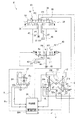
- the hydraulic circuit diagram which shows the structure of the steering operation apparatus of the wheel loader of FIG.
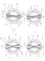
- the cross-sectional block diagram which shows the pilot valve of FIG. (A) (b) Arrow sectional drawing between AA 'of FIG. 3, (c) (d) Arrow sectional drawing between BB' of FIG.
- the side view which shows the connection part and link mechanism of FIG.
- 3A is a schematic diagram of the pilot valve of FIG. 3
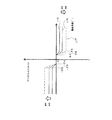
- FIG. 7B is a diagram showing the relationship between the vehicle body-lever deviation angle and the lever reaction force in the pilot valve of FIG. 7A, and FIG.
- FIG.9 The figure which shows the lever reaction force with respect to the vehicle body-lever deviation angle when not applying the assist torque based on the one assist torque information.
- A The figure which shows the 2nd assist torque information (Assist torque given with respect to a vehicle body-lever deviation angle) memorize
- the 2nd assist torque information of Fig.11 (a) The lever reaction force with respect to the vehicle body-lever deviation angle when the assist torque is applied based on FIG.
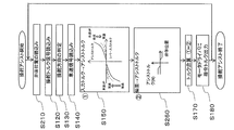
- the flowchart which shows the control method of the wheel loader of Embodiment 1 concerning this invention.
- the figure which shows the 2nd assist torque information (Assist torque given with respect to a valve body position) memorize
- the block diagram which shows the structure of the control part of FIG. The figure which shows the 2nd assist torque information (Assist torque provided with respect to a differential pressure) memorize
- the block diagram which shows the steering operation apparatus in the modification of embodiment concerning this invention.
- FIG. 1 is a schematic diagram showing a configuration of a wheel loader 1 according to the present embodiment.
- the wheel loader 1 according to the present embodiment includes a body frame 2, a work implement 3, a pair of front tires 4, a cab 5, an engine room 6, a pair of rear tires 7, and a steering operation device 8 (see FIG. 2 described later). And.
- the wheel loader 1 performs an earth and sand loading operation using the working machine 3.
- the body frame 2 is a so-called articulate type, and includes a front frame 11, a rear frame 12, and a connecting shaft portion 13.
- the front frame 11 is disposed in front of the rear frame 12.
- the connecting shaft portion 13 is provided at the center in the vehicle width direction, and connects the front frame 11 and the rear frame 12 so as to be swingable.
- the pair of front tires 4 are attached to the left and right of the front frame 11.
- the pair of rear tires 7 are attached to the left and right of the rear frame 12.
- the work machine 3 is driven by hydraulic oil from a work machine pump (not shown).
- the work machine 3 includes a boom 14, a bucket 15, a lift cylinder 16, and a bucket cylinder 17.
- the boom 14 is attached to the front frame 11.
- the bucket 15 is attached to the tip of the boom 14.
- the lift cylinder 16 and the bucket cylinder 17 are hydraulic cylinders.
- One end of the lift cylinder 16 is attached to the front frame 11, and the other end of the lift cylinder 16 is attached to the boom 14.
- the boom 14 swings up and down by the expansion and contraction of the lift cylinder 16.
- One end of the bucket cylinder 17 is attached to the front frame 11, and the other end of the bucket cylinder 17 is attached to the bucket 15 via a bell crank 18. As the bucket cylinder 17 expands and contracts, the bucket 15 swings up and down.
- the cab 5 is placed on the rear frame 12 and includes a handle for steering operation, a joystick lever 24 (see FIG. 2 described later), a lever for operating the work machine 3, and various displays. Devices etc. are arranged.
- the engine room 6 is disposed on the rear frame 12 on the rear side of the cab 5 and houses the engine.
- the steering operation device 8 has steering cylinders 21 and 22, and the steering angle of the front frame 11 with respect to the rear frame 12 is changed by changing the flow rate of oil supplied to the steering cylinders 21 and 22. And the traveling direction of the wheel loader 1 is changed.
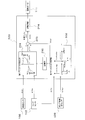
- FIG. 2 is a hydraulic circuit diagram showing the configuration of the steering operation device 8.
- the steering operation device 8 includes a pair of steering cylinders 21 and 22, a steering hydraulic circuit 23, a joystick lever 24, a connecting portion 25, a link mechanism 26, a force applying portion 27, and a control portion 28. And a timing detection unit 29.
- the pair of steering cylinders 21 and 22 are driven by hydraulic pressure.
- the pair of steering cylinders 21 and 22 are arranged side by side on the left and right sides in the vehicle width direction with the connecting shaft portion 13 interposed therebetween.
- the steering cylinder 21 is disposed on the left side of the connecting shaft portion 13 (see FIG. 1).
- the steering cylinder 22 is disposed on the right side of the connecting shaft portion 13.
- One end of each of the steering cylinders 21 and 22 is attached to the front frame 11, and the other end is attached to the rear frame 12.
- the steering cylinder 21 is provided with an extension port 21a and a contraction port 21b
- the steering cylinder 22 is provided with an extension port 22a and a contraction port 22b.
- the steering cylinder 21 when oil is supplied to the contraction port 21b of the steering cylinder 21 and the extension port 22a of the steering cylinder 22, and the oil is discharged from the extension port 21a of the steering cylinder 21 and the contraction port 22b of the steering cylinder 22, the steering cylinder 21 is The steering cylinder 22 expands and contracts. As a result, the steering angle ⁇ s changes and the vehicle turns to the left.
- a steering angle detector 104 that detects the steering angle ⁇ s is provided in the vicinity of the connecting shaft portion 13 disposed between the steering cylinders 21 and 22.
- the steering angle detection unit 104 is configured by, for example, a potentiometer, and the detected steering angle ⁇ s is sent to the control unit 28 as a detection signal.
- the steering cylinder 21 is provided with a cylinder stroke sensor 106 for detecting the cylinder stroke
- the steering cylinder 22 is provided with a cylinder stroke sensor 107 for detecting the cylinder stroke.
- the detection values of the cylinder stroke sensors 106 and 107 may be sent to the control unit 28 to detect the steering angle ⁇ s.
- the steering hydraulic circuit 23 is a hydraulic circuit for adjusting the flow rate of oil supplied to the steering cylinders 21 and 22.
- the steering hydraulic circuit 23 includes a main hydraulic circuit 30 and a pilot hydraulic circuit 40.
- the main hydraulic circuit 30 is a circuit that supplies oil from the main hydraulic source 31 to the steering cylinders 21 and 22 and includes a steering valve 32.
- the main hydraulic power source 31 includes a hydraulic pump and a relief valve.
- the steering valve 32 is a spool type valve, and is a flow rate adjusting valve that adjusts the flow rate of oil supplied to the steering cylinders 21 and 22 in accordance with the input pilot pressure.
- the steering valve 32 has a main pump port P1, a main drain port P2, a first steering port P3, and a second steering port P4.
- the main pump port P1 is connected to the main hydraulic pressure source 31 via the main hydraulic line 36.
- the main drain port P ⁇ b> 2 is connected to a drain tank DT that collects oil via a main drain pipe line 37.
- the first steering port P3 is connected to the contraction port 21b of the steering cylinder 21 and the extension port 22a of the steering cylinder 22 via the first steering pipe line 38.
- the second steering port P4 is connected to the extension port 21a of the steering cylinder 21 and the contraction port 22b of the steering cylinder 22 via the second steering conduit 39.
- the steering valve 32 has a valve body 33 that can move to a neutral position Ns, a left steering position Ls, and a right steering position Rs.
- the valve element 33 When the valve element 33 is disposed at the neutral position Ns, the main pump port P1 and the main drain port P2 communicate with each other. In this case, the first steering port P3 and the second steering port P4 are not in communication with either port.
- the valve element 33 When the valve element 33 is disposed at the left steering position Ls, the main pump port P1 and the first steering port P3 communicate with each other, and the main drain port P2 and the second steering port P4 communicate with each other.
- the valve element 33 When the valve element 33 is disposed at the right steering position Rs, the main pump port P1 and the second steering port P4 communicate with each other, and the main drain port P2 and the first steering port P3 communicate with each other.
- the steering valve 32 has a first pilot chamber 34 and a second pilot chamber 35.
- the valve element 33 When the pilot pressure is not supplied to the first pilot chamber 34 and the second pilot chamber 35 and when the same pilot pressure is supplied to the first pilot chamber 34 and the second pilot chamber 35, the valve element 33 is in the neutral position. Located in Ns. In a state where the pilot pressure is supplied only to the first pilot chamber 34, the valve element 33 is positioned at the left steering position Ls. In a state where the pilot pressure is supplied only to the second pilot chamber 35, the valve element 33 is positioned at the right steering position Rs. When the valve body 33 is located at the left steering position Ls and the right steering position Rs, the steering valve 32 changes the opening area through which oil from the main hydraulic power source 31 passes according to the supplied pilot pressure. . Thereby, the steering valve 32 controls the flow rate of the oil supplied to the steering cylinder 21 or the steering cylinder 22 according to the pilot pressure.
- the pilot hydraulic circuit 40 is a circuit for supplying oil from the pilot hydraulic power source 43 to the first pilot chamber 34 and the second pilot chamber 35 of the steering valve 32.
- the pilot hydraulic circuit 40 includes a variable pressure reducing unit 41 and a pilot valve 42.
- (I) Variable decompression unit The variable decompression unit 41 reduces and adjusts the hydraulic pressure sent from the pilot hydraulic source 43 to the pilot valve 42.
- the variable pressure reducing unit 41 incorporates an electromagnetic pressure reducing valve, and controls the hydraulic pressure in response to a command signal from the control unit 28.
- the pilot valve 42 is a rotary valve that adjusts the pilot pressure input from the pilot hydraulic power source 43 to the steering valve 32.
- the rotary pilot valve 42 has a pilot pump port P5, a pilot drain port P6, a first pilot port P7, and a second pilot port P8.
- the pilot pump port P ⁇ b> 5 is connected to the variable pressure reducing unit 41 through the pilot hydraulic line 44, and the variable pressure reducing unit 41 is connected to the pilot hydraulic pressure source 43.
- the pilot drain port P6 is connected to a drain tank DT that collects oil via a pilot drain pipe line 45.
- the first pilot port P ⁇ b> 7 is connected to the first pilot chamber 34 of the steering valve 32 via the first pilot pipeline 46.
- the second pilot port P8 is connected to the second pilot chamber 35 of the steering valve 32 via the second pilot pipe line 47.
- the pilot valve 42 has a valve body 60 including an operation spool 71 and an operation sleeve 72. With the operation sleeve 72 as a reference, the operation spool 71 has a neutral position Np, a left pilot position Lp, and a right pilot position Rp. Can be moved to. When the operation spool 71 is in the neutral position Np with respect to the operation sleeve 72, the pilot pump port P5, the pilot drain port P6, the first pilot port P7, and the second pilot port P8 communicate with each other.
- FIG. 3 is a cross-sectional configuration diagram of the pilot valve 42.
- the pilot valve 42 mainly includes a valve body portion 60, an operation input shaft 61, a feedback input shaft 62, a housing 63, a first spring 64, a second spring 65, and a feedback portion 66.
- the operation input shaft 61 is rotatably provided around the central axis O and is inserted into the housing 63.
- the operation input shaft 61 is connected to a joystick lever 24 (described later) via a connecting portion 25.
- the operation input shaft 61 rotates at the same rotation angle as the left / right rotation angle ⁇ in of the joystick lever 24.
- the feedback input shaft 62 is arranged coaxially with the operation input shaft 61 and is provided to be rotatable around the central axis O.
- the feedback input shaft 62 is inserted into the housing 63 so as to face the operation input shaft 61.
- the feedback input shaft 62 is connected to the front frame 11 via a link mechanism 26 described later, and rotates at the same rotation angle as the steering angle ⁇ s of the front frame 11 with respect to the rear frame 12.
- the housing 63 accommodates a valve body 60 and a feedback unit 66, and a pilot pump port P5, a pilot drain port P6, a first pilot port P7, and a second pilot port P8 are formed.
- the valve body 60 has an operation spool 71 and an operation sleeve 72, and when the operation spool 71 rotates with respect to the operation sleeve 72, the neutral position Np, the left pilot position Lp, and the right pilot position Rp are obtained.
- the operation spool 71 has a substantially cylindrical shape, is disposed coaxially with the operation input shaft 61, and is connected to the operation input shaft 61.
- the joystick lever 24 is connected to the operation input shaft 61 via a connecting portion 25 described later. When the operator operates the joystick lever 24 to the right of the rotation angle ⁇ in, the operation input shaft 61 and the operation spool 71 are also centered on the central axis O.
- slits 71a and 71b are formed along the circumferential direction at two positions opposed so as to sandwich the central axis O therebetween.
- the operation sleeve 72 is substantially cylindrical, and is disposed outside the operation spool 71 and inside the housing 63 so as to be rotatable with respect to the operation spool 71 and the housing 63.
- right rotation and left rotation indicate rotation directions when viewed from above.
- FIG. 4A is an arrow cross-sectional view taken along AA ′ perpendicular to the central axis O.
- FIG. 4 (a) the operation spool 71 is provided with square holes 71c and 71d on the opposing walls in the diameter direction.
- rectangular grooves 72c and 72d are formed in the diametrically opposed walls at the end of the operation sleeve 72 on the operation input shaft 61 side.
- the first spring 64 is formed of two sets of leaf spring portions 64a in which a plurality of convex leaf springs are overlapped.
- the two sets of leaf spring portions 64a are arranged so that the protrusions face each other so as to be X-shaped in FIG.
- the two sets of leaf spring portions 64 a pass through the holes 71 c and 71 d of the operation spool 71, and both ends are inserted into the grooves 72 c and 72 d of the operation sleeve 72.
- the operation spool 71 and the operation sleeve 72 are connected by the first spring 64.
- the positions in the circumferential direction of the hole 71c and the groove 72c substantially coincide with each other, and the positions in the circumferential direction of the hole 71d and the groove 72d substantially coincide with each other. It is in a position.
- the operation spool 71 rotates with respect to the operation sleeve 72, and the operation spool 71 moves with respect to the operation sleeve 72 in the left pilot position Lp or the right pilot. Move to position Rp.
- the operation spool 71 rotates to the right with respect to the operation sleeve 72 and moves to the right pilot position Rp.
- the operation spool 71 rotates to the left with respect to the operation sleeve 72 and moves to the left pilot position Lp.
- the first spring 64 biases the operation spool 71 so as to be positioned at the neutral position Np with respect to the operation sleeve 72.
- the feedback unit 66 feeds back the steering angle ⁇ s of the front frame 11 with respect to the rear frame 12 to the valve body 60.
- the feedback portion 66 mainly includes a feedback spool 73, a feedback sleeve 74, a drive shaft 75, a first center pin 76, and a restriction portion 78.
- the drive shaft 75 is disposed between the operation input shaft 61 and the feedback input shaft 62 and coaxially with the operation input shaft 61 and the feedback input shaft 62 (center axis O).
- the drive shaft 75 is disposed inside the operation spool 71.
- a first center pin 76 is disposed perpendicular to the center axis O at the end of the drive shaft 75 on the operation input shaft 61 side. Both ends of the first center pin 76 pass through the slits 71 a and 71 b and are fixed to the operation sleeve 72.
- the rotation angle of the operation spool 71 with respect to the operation sleeve 72 is restricted to an angle within a predetermined range by the first center pin 76 and the slits 71a and 71b. Further, since the first center pin 76 is fixed to the operation sleeve 72 and the drive shaft 75, when the drive shaft 75 rotates, the operation sleeve 72 integrated with the drive shaft 75 also rotates.
- the feedback spool 73 has a substantially cylindrical shape, is disposed coaxially with the feedback input shaft 62, and is connected to the feedback input shaft 62. Near the feedback input shaft 62 of the feedback spool 73, slits 73a and 73b are formed along the circumferential direction at two positions facing each other so as to sandwich the central axis O therebetween. A drive shaft 75 is disposed inside the feedback spool 73.
- the feedback input shaft 62 is connected to the front frame 11 via a link mechanism 26 described later. When the front frame 11 rotates to the right of the steering angle ⁇ s with respect to the rear frame 12, the feedback input shaft 62 and the feedback spool 73 are also It rotates to the right of the same rotation angle ⁇ s as the steering angle ⁇ s.
- the feedback sleeve 74 has a substantially cylindrical shape, and is disposed outside the feedback spool 73 and inside the housing 63 so as to be rotatable with respect to the feedback spool 73 and the housing 63.
- the restricting portion 78 restricts the rotation of the feedback sleeve 74 with respect to the feedback spool 73 to an angle within a predetermined range.
- the restricting portion 78 includes a second center pin 77 and wall portions 73ae and 73be (see FIG. 7 described later) at both ends in the circumferential direction of the slits 73a and 73b.
- the second center pin 77 is arranged perpendicular to the center axis O at the end of the drive shaft 75 on the feedback input shaft 62 side. Both ends of the second center pin 77 are fixed to the feedback sleeve 74 through the slits 73a and 73b. The rotation of the feedback sleeve 74 relative to the feedback spool 73 is restricted to an angle within a predetermined range by the second center pin 77 and the slits 73a and 73b. Further, since the second center pin 77 is fixed to the feedback sleeve 74 and the drive shaft 75, when the feedback sleeve 74 rotates, the drive shaft 75 integrated with the feedback sleeve 74 also rotates. With the rotation of the drive shaft 75, the operation sleeve 72 fixed to the drive shaft 75 by the first center pin 76 rotates.
- FIG. 4C is a cross-sectional view taken along the line BB ′ in FIG.
- the feedback spool 73 is provided with square holes 73c and 73d in each of the opposing walls in the diameter direction.
- the second spring 65 is formed of two sets of leaf spring portions 65a obtained by superimposing a plurality of convex leaf springs.
- the two sets of leaf spring portions 65a are arranged so that the protrusions face each other so as to be X-shaped in FIG.
- the two sets of leaf spring portions 65 a pass through the holes 73 c and 73 d of the feedback spool 73, and both ends are inserted into the grooves 74 c and 74 d of the feedback sleeve 74.
- the feedback spool 73 and the feedback sleeve 74 are connected by the second spring 65.
- the hole 73c and the groove 74c are aligned in the circumferential direction
- the hole 73d and the groove 74d are aligned in the circumferential direction.
- the feedback sleeve 74 is urged by the second spring 65 so that the circumferential positions of the grooves 74 c and 74 d are aligned with the circumferential positions of the holes 73 c and 73 d of the feedback spool 73.
- the first spring 64 bends until the operation spool 71 is restricted with respect to the operation sleeve 72, but the first spring 64 starts to bend by applying a force greater than the reaction force generated in the first spring 64 until the operation spool 71 is restricted.
- Two springs 65 are set. Although details will be described later with reference to FIG. 7, when the operation spool 71 rotates to an angle regulated with respect to the operation sleeve 72 and further the joystick lever 24 is operated, as shown in FIG.
- the second spring 65 is bent and the feedback sleeve 74 rotates with respect to the feedback spool 73.
- FIG. 4D is a cross-sectional view taken along the line BB ′ in FIG. 3 and is viewed from below, so that the arrow in the rotation direction is opposite to that in FIG. 4B. .
- the operation sleeve 72 fixed via the feedback sleeve 74, the second center pin 77, the drive shaft 75, and the first center pin 76 rotates, and a change occurs in the difference between the rotation angles of the operation spool 71 and the operation sleeve 72.
- the pilot pressure is changed.
- the position of the operation spool 71 with respect to the operation sleeve 72 depends on the difference ⁇ between the rotation angle ⁇ in of the operation input shaft 61 and the rotation angle fb of the feedback input shaft 62 (which coincides with the steering angle ⁇ s). , Move to the neutral position Np, the left pilot position Lp, or the right pilot position Rp. When the rotation angle difference ⁇ is zero, the operation spool 71 is positioned at the neutral position Np with respect to the operation sleeve 72.
- the pilot valve 42 passes oil from the pilot hydraulic power source 43 according to the rotation angle difference ⁇ .
- the opening area to be changed is changed.
- the pilot pressure sent from the pilot valve 42 to the steering valve 32 is adjusted according to the rotation angle difference ⁇ .
- the operation input shaft 61 is provided with a first rotation angle detection unit 101 configured by, for example, a rotary sensor.
- the first rotation angle detection unit 101 detects the rotation angle ⁇ in of the operation input shaft 61.
- the feedback input shaft 62 is provided with a second rotation angle detection unit 102 configured by, for example, a rotary sensor.
- the rotation angles ⁇ in and ⁇ fb detected by the first rotation angle detection unit 101 and the second rotation angle detection unit 102 are sent to the control unit 28 as detection signals.
- the steering angle detection unit 104 detects the steering angle ⁇ s in the connecting shaft unit 13 as well, but the rotation angle ⁇ fb of the feedback input shaft 62 coincides with the steering angle ⁇ s.
- the portion 104 may not be provided.
- FIG. 5 is a side view showing the configuration inside the cab 5.
- a driver's seat 5a on which an operator is seated is provided in the cab 5.
- a steering box 80 is disposed on the left side of the driver seat 5a in the vehicle width direction.
- the joystick lever 24 is disposed to project obliquely upward from the steering box 80 toward the front.
- the connecting portion 25 connects the joystick lever 24 and the pilot valve 42.
- the connecting portion 25 mainly has a steering operation shaft 81, a connecting bar 82, and a universal joint portion 83.
- the steering operation shaft 81 is disposed in the vertical direction, and is supported by the steering box 80 so as to be rotatable about its central axis E.
- the connection bar 82 is disposed in the steering box 80 and connects the joystick lever 24 and the steering operation shaft 81.
- the steering operation shaft 81 is configured by sequentially connecting a lever side shaft portion 81a, an input shaft portion 81b, and a valve side shaft portion 81c (see FIG. 8 described later). That is, one end of the lever side shaft portion 81a is connected to the connecting bar 82, and the other end of the lever side shaft portion 81a is connected to one end of the input shaft portion 81b.
- the other end of the input shaft portion 81 b is connected to one end of the valve side shaft portion 81 c, and the other end of the valve side shaft portion 81 c is connected to the universal joint portion 83.
- Auxiliary force or reaction force from a force applying unit 27 described later is input to the input shaft portion 81b.
- the universal joint 83 connects the steering operation shaft 81 and the operation input shaft 61 of the pilot valve 42 disposed in the vicinity of the driver's seat 5a.
- the universal joint part 83 has a center part 83a that can be expanded and contracted, and joint parts 83b and 83c that are arranged at both ends of the center part 83a.
- the joint portion 83 b is connected to the steering operation shaft 81.
- the joint portion 83 c is connected to the operation input shaft 61.
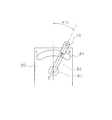
- FIG. 6 is a plan view of the vicinity of the joystick lever 24 as viewed from above.
- the joystick lever 24 is formed to project obliquely upward from an arc-shaped hole 84 formed on the upper surface of the steering box 80.
- the joystick lever 24 can turn in the horizontal direction about the steering operation shaft 81 (specifically, the central axis E). Further, an R mark is formed on the right edge of the hole 84 of the steering box 80, and an L mark is formed on the left edge.
- the steering operation shaft 81 when the operator rotates the joystick lever 24 from the center position to the right by the rotation angle ⁇ in, the steering operation shaft 81 also rotates to the right by the rotation angle ⁇ in.
- the rotation of the rotation angle ⁇ in of the steering operation shaft 81 is transmitted to the operation input shaft 61 via the universal joint portion 83, and the operation input shaft 61 also rotates clockwise to the rotation angle ⁇ in.
- the joystick lever 24 is rotated counterclockwise.
- the link mechanism 26 includes a follow-up lever 91, a follow-up link 92, and a bracket 93.
- the follow-up link 92 is fixed to the feedback input shaft 62 of the pilot valve 42.
- the bracket 93 is fixed to the front frame 11.
- the follow-up link 92 connects the follow-up lever 91 and the bracket 93.
- the pilot valve 42 arranged in the rear frame 12 and the front frame 11 are linked.
- the link mechanism 26 the steering angle ⁇ s of the front frame 11 with respect to the rear frame 12 and the rotation angle ⁇ fb of the feedback input shaft 62 become the same angle. That is, when the front frame 11 rotates to the right of the steering angle ⁇ s about the connecting shaft portion 13 with respect to the rear frame 12, the feedback input shaft 62 also rotates to the right of the rotation angle ⁇ s via the link mechanism 26, and the steering When the angle ⁇ s rotates to the left, the feedback input shaft 62 also rotates counterclockwise by the rotation angle ⁇ s via the link mechanism 26.
- FIG. 7A schematically shows the pilot valve 42.
- FIG. 7B is a diagram showing the relationship between the vehicle body-lever deviation angle and the lever reaction force.
- FIG. 7C is a cross-sectional view taken along arrows CC ′, DD ′, EE ′, and FF ′ of FIG. 7A when the deviation angle ⁇ is zero.
- FIG. 7D is a cross-sectional view taken along arrows CC ′, DD ′, EE ′, and FF ′ in FIG. 7A when the deviation angle ⁇ is ⁇ 2.
- FIG. 7E is an arrow cross-sectional view between CC ′, DD ′, EE ′, and FF ′ in FIG. 7A when the deviation angle ⁇ is ⁇ 3.
- the cross-sectional views between CC ′, DD ′, EE ′, and FF ′ are all viewed from above.
- play of the joystick lever 24 is not taken into consideration for easy understanding of the explanation.
- the operation input shaft 61 When the operator rotates the joystick lever 24 from the center position at the rotation angle ⁇ in, the operation input shaft 61 also rotates at the rotation angle ⁇ in.
- the steering angle ⁇ s gradually increases following the rotation angle ⁇ in.
- the rotation angle ⁇ in of the joystick lever 24 indicates a target steering angle, and the steering angle ⁇ s indicates an actual actual steering angle.
- the feedback input shaft 62 In response to the change in the steering angle ⁇ s, the feedback input shaft 62 also rotates at the same rotation angle ⁇ s as the steering angle ⁇ s. Then, the feedback spool 73 is rotated together with the feedback input shaft 62, and the feedback sleeve 74 connected through the second spring 65 is also rotated by the rotation.
- the operation sleeve 72 is also rotated by the rotation of the feedback sleeve 74. That is, the difference between the rotation angles of the operation spool 71 and the operation sleeve 72 corresponds to the deviation angle ⁇ (see FIG. 4B).
- the first spring 64 urges the operation spool 71 to the neutral position Np with respect to the operation sleeve 72, in order to increase the deviation angle ⁇ , the first spring 64 is against the urging force of the first spring 64. It is necessary to operate the joystick lever 24.
- the first spring 64 has a spring characteristic S1 shown in FIG. In the spring characteristic S1 of the first spring 64, in order to rotate the operation input shaft 61, it is necessary to operate the joystick lever 24 with a force greater than or equal to the initial reaction force F1 (a force necessary to start bending the first spring 64). There is. In the spring characteristic S1 of the first spring 64, the lever reaction force increases as the deviation angle ⁇ increases. That is, as the deviation angle ⁇ increases, the force required to operate the joystick lever 24 increases.
- the first center pin 76 is disposed at the center of the slits 71a and 71b of the operation spool 71 at the neutral position Np where the deviation angle ⁇ is zero.
- the second center pin 77 is disposed at the center of the slits 73 a and 73 b of the feedback spool 73. Then, the deviation angle ⁇ is increased by rotating the joystick lever 24 to the right side, for example, and when the deviation angle ⁇ reaches the angle ⁇ 2, the first center pin 76 moves in the circumferential direction of the slit 71a as shown in FIG.
- the second center pin 77 is disposed at the center of the slits 73 a and 73 b of the feedback spool 73. If the reaction force by the first spring 64 when the deviation angle ⁇ is the angle ⁇ 2 is F2, the initial reaction force (because the second spring 65 starts to bend as shown in the spring characteristic S2 of the second spring 65). This is because the necessary force is set to F2. Note that the initial reaction force of the second spring 65 may be set to be larger than F2, or may be F2 or more.
- the second center pin 77 When the deviation angle ⁇ reaches ⁇ 3, the second center pin 77 is formed in the circumferential direction of the slit 73b and the wall portion 73ae formed in the circumferential direction of the slit 73a as shown in FIG. It contacts the wall portion 73be. As described above, the second center pin 77 is rotatable by an angle ( ⁇ 3- ⁇ 2). That is, the pilot valve 42 is configured so that the deviation angle ⁇ cannot be larger than the angle ⁇ 3. For this reason, as shown in FIG. 7B, the lever reaction force rises linearly at an angle ⁇ 3. When the second center pin 77 abuts against the wall portions 73ae and 73be vigorously, a sudden recoil occurs, causing a burden on the operator's wrist. This angle ⁇ 3 is also called a catch-up angle.
- the deviation angle ⁇ is a negative value.
- the first center pin 76 contacts the wall portions 71ae and 71be at - ⁇ 2
- the second center pin 77 contacts the wall portions 73ae and 73be at - ⁇ 3.
- the pilot valve 42 is configured so that the absolute value of the deviation angle ⁇ does not become larger than the angle ⁇ 3.
- FIG. 8 is a perspective view showing the force applying unit 27.
- the force applying unit 27 applies an assisting force or a reaction force to the operation of the joystick lever 24.
- the force applying unit 27 includes an electric motor 111 and a worm gear 112.
- the worm gear 112 has a cylindrical worm 112a and a worm wheel 112b.
- the worm wheel 112b is provided around the input shaft portion 81b described above, and meshes with the cylindrical worm 112a.
- the output shaft of the electric motor 111 is connected to the cylindrical worm 112a, and rotates the cylindrical worm 112a around its central axis.
- the electric motor 111 is driven based on a command from the drive circuit 204 provided in the control unit 28.
- the first end 81b1 of the input shaft portion 81b is connected to the lever side shaft portion 81a, and the second end 81b2 is connected to the valve side shaft portion 81c.
- the electric motor 111 is driven, the cylindrical worm 112a is rotated, the worm wheel 112b is rotated by the rotation, and a rotational force is also generated in the input shaft portion 81b fixed to the worm wheel 112b.
- a rotational force is also generated in the input shaft portion 81b fixed to the worm wheel 112b.
- an auxiliary force is applied to the operation of the joystick lever 24 by applying a force in the clockwise direction to the input shaft portion 81b.
- a reaction force is applied to the operation of the joystick lever 24 by applying a force in the left rotation direction to the input shaft portion 81b.
- the torque sensor 103 is provided in the input shaft portion 81b.
- the torque sensor 103 detects torque generated in the input shaft portion 81b when the operator applies the joystick lever 24.
- the torque sensor 103 according to the present embodiment detects, for example, the rotation direction of the input shaft portion 81b and the torque generated in the input shaft portion 81b by detecting torsion of the torsion bar with a coil. The detected rotation direction and torque T are output to the control unit 28 as a steering torque signal.
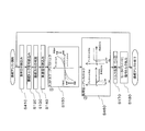
- FIG. 9 is a block diagram illustrating a configuration of the control unit 28.
- the control unit 28 includes a storage unit 200, a first assist torque determination unit 201, a second assist torque determination unit 202, a calculation unit 203, and a drive circuit 204.
- the first assist torque determination unit 201, the second assist torque determination unit 202, and the calculation unit 203 are executed by an arithmetic device such as a CPU.
- the storage unit 200 stores a relationship of assist torque to be applied to lever input torque (first assist torque information) for each speed. In addition, the storage unit 200 stores a relationship of assist torque to be applied to the deviation angle ⁇ (second assist torque information).
- the first assist torque information and the second assist torque information are set in advance. The first assist torque information and the second assist torque information will be described in detail later.
- the storage unit 200 may be provided in the control unit 28 or may be provided outside the control unit 28.
- the storage unit 200 is configured by a RAM, a ROM, an HDD, or the like.
- the first assist torque determination unit 201 receives a steering torque signal (S (T0) shown in FIG. 9) from the torque sensor 103 and a speed signal (S (V) shown in FIG. 9) from the vehicle speed sensor 105. Then, the first assist torque determination unit 201 calculates the first assist torque from the steering torque signal from the torque sensor 103 and the speed signal from the vehicle speed sensor 105 based on the first assist torque information stored in the storage unit 200. decide. The first assist torque determination unit 201 outputs the determined first assist torque as a first assist torque signal (S (T1) shown in FIG. 9).
- the second assist torque determination unit 202 uses a first rotation angle signal (S ( ⁇ in) shown in FIG. 9) indicating the rotation angle ⁇ in detected by the first rotation angle detection unit 101 and the second rotation angle detection unit 102.
- the second assist torque determination unit 202 calculates the difference between the rotation angle ⁇ in and the rotation angle ⁇ fb to calculate the deviation angle ⁇ ( ⁇ in ⁇ fb).
- the second assist torque determination unit 202 determines the second assist torque from the deviation angle ⁇ based on the second assist torque information stored in the storage unit 200.
- the second assist torque information is used to sensuously notice the timing at which the tilting operation (articulating operation) of the front frame 11 relative to the rear frame 12 starts when the joystick lever 24 is operated. , Set to generate resistance to operation.
- the second assist torque determination unit 202 outputs the determined second assist torque as a second assist torque signal (S (T2) shown in FIG. 9).
- the calculation unit 203 calculates the sum of the first assist torque determined by the first assist torque determination unit 201 and the second assist torque determined by the second assist torque determination unit 202, and applies the sum to the input shaft unit 81b. A target assist torque is calculated.
- the calculation unit 203 outputs the calculated target assist torque to the drive circuit 204 as a target assist torque signal (S (T3) shown in FIG. 9).
- the drive circuit 204 drives the electric motor 111 based on the calculated target assist torque.
- the control unit 28 can apply an assisting force or a reaction force to the operator's operation of the joystick lever 24 based on the torque T, the deviation angle ⁇ , and the speed V.
- the control of the electric motor 111 and the variable pressure reducing unit 41 by the control unit 28 may be performed by wire or may be performed by radio.
- the timing detection unit 29 detects the timing at which resistance is generated with respect to the operation of the joystick lever 24 in order to make the operator feel the start timing of the articulating operation.
- the timing detection unit 29 includes the first rotation angle detection unit 101 and the second rotation angle detection unit 102 described above.
- the first rotation angle detection unit 101 is provided on the operation input shaft 61 and detects the rotation angle ⁇ in of the operation input shaft 61.
- the operation spool 71 is located at the neutral position Np shown in FIG.
- the pilot pressures of the first pilot chamber 34 and the second pilot chamber 35 of the steering valve 32 are the same, and the valve body 33 of the steering valve 32 is also in the neutral position Ns.
- the operator applies an operating force Fin to rotate the joystick lever 24 from the center position to the right as shown in FIG.
- the operating force Fin exceeds F1 of the first spring 64
- the operation input shaft 61 rotates to the right in the same manner as the joystick lever 24, and the rotation angle ⁇ in of the operation input shaft 61 increases.
- the operation spool 71 rotates clockwise with respect to the operation sleeve 72 as the operation input shaft 61 rotates.
- the operation sleeve 72 is integrated with the feedback sleeve 74, and the feedback sleeve 74 is connected to the feedback spool 73 by the second spring 65.
- the initial reaction force F2 of the 2nd spring 65 is more than the reaction force of the spring characteristic S1 of the 1st spring 64 shown in FIG.7 (b). Therefore, the operation sleeve 72 does not rotate with the operation spool 71, and the operation spool 71 rotates clockwise with respect to the operation sleeve 72.
- the operation spool 71 rotates clockwise with respect to the operation sleeve 72 and moves to the right pilot position Rp, where pilot pressure is supplied to the second pilot port P8 and pilot pressure is supplied to the second pilot chamber 35. .
- the valve element 33 of the steering valve 32 moves to the right steering position Rs, oil is supplied to the extension port 21a of the steering cylinder 21 and the contraction port 22b of the steering cylinder 22, and the contraction port 21b of the steering cylinder 21 and Oil is discharged from the extension port 22 a of the steering cylinder 22.
- the articulating operation starts, the steering angle ⁇ s gradually increases, and the front frame 11 is directed to the right with respect to the rear frame 12 (see R in FIG. 2).
- the change in the steering angle ⁇ s is transmitted to the feedback input shaft 62 by the link mechanism 26, and the feedback input shaft 62 rotates at the rotation angle ⁇ s.
- the operation input shaft 61 When the operator stops the joystick lever 24 at a predetermined rotation angle ⁇ 1, the operation input shaft 61 also stops at the rotation angle ⁇ 1. On the other hand, since the steering angle ⁇ s gradually increases, the rotation angle ⁇ s of the feedback input shaft 62 also increases.
- the feedback spool 73 rotates together with the feedback input shaft 62, and the feedback sleeve 74 connected to the feedback spool 73 via the second spring 65 also rotates. Since the feedback sleeve 74 is integrated with the operation sleeve 72 via the first center pin 76, the second center pin 77, and the drive shaft 75, the operation sleeve 72 rotates as the feedback sleeve 74 rotates.
- the rotation angle of the operation sleeve 72 and the operation spool 71 (deviation angle ⁇ ) is reduced by the rotation of the operation sleeve 72.
- the deviation angle ⁇ becomes zero.
- the operation spool 71 of the pilot valve 42 is located at the neutral position Np with respect to the operation sleeve 72.
- the pilot pressure in the first pilot chamber 34 and the second pilot chamber 35 of the steering valve 32 is the same, and the steering valve 32 is also in the neutral position Ns. For this reason, oil is not supplied to or discharged from the left and right steering cylinders 21 and 22, and the steering angle ⁇ s is maintained at the rotation angle ⁇ 1.
- the steering angle ⁇ s is also maintained at the same rotation angle ⁇ 1.
- the front frame 11 is maintained to the right with respect to the rear frame 12 in the direction of the rotation angle ⁇ 1.
- the operation input shaft 61 rotates in the same manner, and the rotation angle ⁇ in of the operation input shaft 61 decreases.
- the operation spool 71 rotates left with respect to the operation sleeve 72 and moves to the left pilot position Lp, and the pilot pressure is supplied to the first pilot port P7.
- the valve element 33 of the steering valve 32 moves to the left steering position Ls, oil is supplied to the contraction port 21b of the steering cylinder 21 and the extension port 22a of the steering cylinder 22, and the extension port 21a of the steering cylinder 21 and Oil is discharged from the contraction port 22 b of the steering cylinder 22.
- the steering angle ⁇ s gradually decreases from the rotation angle ⁇ 1.
- the change in the steering angle ⁇ s is transmitted to the feedback input shaft 62 by the link mechanism 26, and the feedback input shaft 62 rotates with the same change in the rotation angle as the change in the steering angle ⁇ s.
- the pilot pressures of the first pilot chamber 34 and the second pilot chamber 35 of the steering valve 32 are the same, and the steering valve 32 is also in the neutral position Ns. For this reason, oil is not supplied to or discharged from the left and right steering cylinders 21 and 22, and the steering angle ⁇ s is also returned to zero and maintained. Thereby, the front frame 11 is returned to the direction along the front-rear direction with respect to the rear frame 12.
- the wheel loader 1 of the present embodiment changes the assist torque to be applied to the operation of the joystick lever 24 according to the torque and speed based on the first assist torque information. Furthermore, the wheel loader 1 of the present embodiment determines the timing at which the tilting operation (articulating operation) of the front frame 11 with respect to the rear frame 12 starts when the joystick lever 24 is operated based on the second assist torque information. It is set to generate a resistance to the operation in order to notice it sensuously. First, the first assist torque information and the second assist torque information will be described.
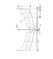
- FIG. 10A is a diagram illustrating assist torque (first assist torque information) for each vehicle speed applied to the input torque.
- a solid line L1 indicates assist torque information when the vehicle speed is 0 km / h
- a dotted line L2 indicates assist torque information when the vehicle speed is 25 km / h
- a one-dot chain line L3 indicates a vehicle speed of 40 km / h. Assist torque information at.
- the positive lever input torque indicates the torque generated by the rotation of the joystick lever 24 to the right side
- the negative lever input torque is generated by the rotation of the joystick lever 24 to the left side. Torque is shown.
- a case where a positive assist torque applies a force to the input shaft portion 81b in a clockwise rotation and a case where a negative assist torque applies a force to the input shaft portion 81b in a counterclockwise rotation are shown.
- L1a indicates the assist torque when the joystick lever 24 is rotated to the right when the vehicle speed is 0 km / h
- L1b rotates the joystick lever 24 to the left when the vehicle speed is 0 km / h
- Assist torque when L2a indicates assist torque when the joystick lever 24 is rotated to the right when the vehicle speed is 25 km / h
- L2b rotates the joystick lever 24 to the left when the vehicle speed is 25 km / h.
- L1a, L2a, and L3a indicate a case where the joystick lever 24 is rotated to the right.
- the assist torque is a positive value
- a force is applied to the input shaft portion 81b in the clockwise rotation.
- L1b, L2b, and L3b indicate the case where the joystick lever 24 is rotated to the left.
- the assist torque is a negative value
- a force is applied to the input shaft portion 81b for counterclockwise rotation. In this way, an auxiliary force is added to the operation of the joystick lever 24.
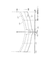
- FIG. 10B is a diagram showing a lever reaction force with respect to the vehicle body-lever deviation angle when the assist torque shown in FIG. 10A is applied and when the assist torque is not applied.
- FIG. 10B shows a case where the positive deviation angle ⁇ moves the joystick lever 24 to the right side, and a negative deviation angle ⁇ shows the case where the joystick lever 24 moves to the left side. That is, as shown in FIG.
- the angle ⁇ 3 indicates an angle at which the operation is restricted when the joystick lever 24 is rotated to the right, and the angle ⁇ 3 is when the joystick lever 24 is rotated to the left. Indicates the angle at which the operation is restricted.
- the angle ⁇ 2 indicates an angle at which the first center pin 76 contacts the wall portions 71ae and 71be when the joystick lever 24 is rotated clockwise, and the angle ⁇ 2 indicates the joystick lever. The angle at which the first center pin 76 abuts against the wall portions 71ae and 71be when 24 is rotated counterclockwise is shown.
- the solid line L4 indicates the lever reaction force with respect to the deviation angle when the vehicle speed is 0 km / h
- the dotted line L5 indicates the lever reaction force with respect to the deviation angle when the vehicle speed is 25 km / h
- the alternate long and short dash line L6 indicates that the vehicle speed is 40 km.
- the lever reaction force with respect to the deviation angle in the case of / h is shown.
- FIG. 10B the case where the assist torque is not applied is indicated by a two-dot chain line L7.
- FIG. 10 (b) shows the same state as FIG. 7 (b).
- L4 to L7 are line symmetric with respect to the vertical axis, respectively.
- an assist force is applied symmetrically to the left and right operations, and the assist torque is increased.
- the lever reaction force is smaller than when not applied (L7).
- the lever reaction force is set to increase as the speed increases. Thereby, both operability at low speed and running stability at high speed can be achieved.
- the first assist torque determining unit 201 determines the first assist torque from the stored assist torque information of the three vehicle speeds based on the detected value of the vehicle speed sensor 105, but the detected value from the vehicle speed sensor 105 is 3 When the speed is between two speeds (for example, 12 km / h), the assist torque at the vehicle speed is calculated by interpolation calculation. Thus, by calculating the first assist torque by interpolation calculation, the assist torque can be continuously changed according to the speed change.
- the second assist torque information indicates the assist torque that is applied to generate resistance to the operation of the joystick lever 24 before the articulate operation starts when the joystick lever 24 is operated.
- FIG. 11A is a diagram showing assist torque (second assist torque information) with respect to the vehicle body-lever deviation angle ( ⁇ ). Also in FIG. 11A, a positive vehicle body-lever deviation angle ⁇ ( ⁇ in ⁇ s) shows a case where the joystick lever 24 is operated to the right side, and a negative vehicle body-lever deviation angle ⁇ is operated to the left side. Indicates when to do. In addition, a case where a positive assist torque applies a force to the input shaft portion 81b in a clockwise rotation and a case where a negative assist torque applies a force to the input shaft portion 81b in a counterclockwise rotation are shown.
- a reaction force is generated when the deviation angle ⁇ becomes an angle ⁇ ⁇ 4, and the assist torque is set so that the reaction force increases until the deviation angle becomes ⁇ ⁇ 5. Yes.
- the input shaft portion 81b is forced in the counterclockwise direction until the deviation angle ⁇ becomes + ⁇ 5. Is added.
- This force in the counterclockwise direction is set so that the resistance increases with a constant slope from + ⁇ 4 to + ⁇ 5. After the deviation angle reaches + ⁇ 5, the counterclockwise force applied to the input shaft portion 81b is constant.
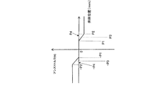
- FIG. 11B is a diagram showing the lever reaction force with respect to the vehicle body-lever deviation angle when the assist torque is applied based on the second assist torque information shown in FIG. 11A and when the assist torque is not applied.
- a solid line L8 indicates a case where the assist torque is applied
- a two-dot chain line L9 indicates a case where the assist torque is not applied.
- L9 is the same graph as L7 in FIG. 10B and FIG. 7B.
- a graph indicating the opening area of the steering valve 32 with respect to the deviation angle ⁇ is indicated by a one-dot chain line L10.
- L10 the vertical axis is the opening area.
- the opening area of the steering valve 32 is also increased, the deviation angle reaches a maximum value near ⁇ 2, and thereafter the opening area is increased even if the absolute value of the deviation angle increases. It is constant.
- the articulate operation start timing is slightly delayed from ⁇ ⁇ 6 that is the opening timing of the steering valve 32, and is indicated by ⁇ ⁇ 7.
- ⁇ 7 to + ⁇ 7 correspond to the play angle of the joystick lever 24.
- the angle ⁇ 4 is smaller than the angle ⁇ 2 shown in FIGS. 7B and 10B, and the angle ⁇ 4 is set to a value larger than ⁇ 2.
- the opening angle + ⁇ 6 is set between + ⁇ 4 and + ⁇ 5, and the opening angle ⁇ 6 is set between ⁇ 5 and ⁇ 4.
- resistance is generated with respect to the operation of the joystick lever 24 before the start of the articulate operation.
- L8 when the operator operates the joystick lever 24, the inclination from the neutral position to the deviation angle ⁇ 4 (increase in lever reaction force with respect to the deviation angle ⁇ ) is due to the elastic force of the first spring 64.
- the inclination from + ⁇ 4 to + ⁇ 5 is due to the increase in resistance due to the second assist torque and the elastic force of the first spring 64 shown in FIG.
- the slope of the graph which is the rate of increase of the lever reaction force with respect to the absolute value of the deviation angle when the absolute value of the deviation angle is between ⁇ 4 and ⁇ 5, is the deviation angle. Is larger than the slope up to ⁇ 4. As a result, the operator can feel the timing at which the articulate operation starts as resistance, and therefore, it is easy to perform a fine operation that performs the articulate operation only slightly.
- FIG. 12 is a flowchart showing the control operation of the force applying unit 27.
- the second assist torque determination unit 202 of the control unit 28 receives the first rotation angle signal (S ( ⁇ 1) shown in FIG. 9) from the first rotation angle detection unit 101.
- the second rotation angle signal (S ( ⁇ 2) shown in FIG. 9) is received from the second rotation angle detection unit 102.
- the first assist torque determination unit 201 of the control unit 28 receives a steering torque signal (S (T0) shown in FIG. 9) from the torque sensor 103.
- the steering torque signal includes information on the magnitude of the torque and the rotation direction. For example, in the case of a positive torque value, the torque is generated by the right rotation of the input shaft portion 81b. In the case of a negative torque value, the torque generated by the left rotation of the input shaft portion 81b is used. And information about the direction of rotation.
- step S130 the control unit 28 determines the steering direction of the joystick lever 24 based on the steering torque signal. This steering direction determines the direction of rotation of the electric motor 111 when the force is applied.
- step S140 the first assist torque determination unit 201 of the control unit 28 acquires a vehicle speed V signal (S (V) shown in FIG. 9) from the vehicle speed sensor 105.
- step S ⁇ b> 150 the first assist torque determination unit 201 determines the first assist torque based on the first assist information stored in the storage unit 200. Then, the first assist torque determining unit 201 outputs the determined first assist torque as a first assist torque signal (S (T1) shown in FIG. 9).
- the control unit 28 stores three pieces of first assist torque information shown in FIG. 10 (when the vehicle speed is 0 km / h, 25 km / h, and 40 km / h).
- the control unit 28 calculates the assist torque at the vehicle speed by interpolation calculation. As described above, the control unit 28 determines the first assist torque by the interpolation calculation. Note that by calculating the first assist torque by interpolation calculation, the assist torque can be continuously changed according to the speed change.
- step S160 the second assist torque determination unit 202 determines the second assist torque based on the second assist torque information shown in FIG. 11A from the deviation angle ⁇ calculated in step S110. Then, the second assist torque determination unit 202 outputs the determined second assist torque as a second assist torque signal (S (T2) shown in FIG. 9).
- step S170 the calculation unit 203 adds the first assist torque and the second assist torque, calculates the target assist torque, and uses the calculated target assist torque as a target assist torque signal (S (T3 shown in FIG. 9). )) To the drive circuit 204.
- the target assist torque is a positive / negative value and includes information on the rotation direction. For example, when rotating to the right, the assist force is applied in the first assist torque information shown in FIG. 10A, but the deviation angle ⁇ exceeds the angle ⁇ 4 in the second assist torque information shown in FIG. And reaction force is given.
- the target assist torque becomes a negative value.
- the force of the magnitude of subtracting is applied to the left rotation.
- the target assist torque will be a positive value, and the force that is the magnitude of the absolute value of the assist force minus the absolute value of the reaction force Given to rotation.
- FIG. 13 is a diagram showing a lever reaction force with respect to a deviation angle when the assist torque synthesized by the calculation unit 203 is applied to the operation of the joystick lever 24.
- the solid line L11 indicates the lever reaction force with respect to the deviation angle when the vehicle speed is 0 km / h
- the dotted line L12 indicates the lever reaction force with respect to the deviation angle when the vehicle speed is 25 km / h
- the alternate long and short dash line L13 indicates that the vehicle speed is 40 km.
- the lever reaction force with respect to the deviation angle in the case of / h is shown.
- the case where the assist torque is not applied is indicated by a two-dot chain line L14.
- L14 is the same graph as L9 and L7.
- the lever reaction force is set to increase as the speed increases. Thereby, both operability at low speed and running stability at high speed can be achieved. Further, for each speed (solid line L11, dotted line L12, and alternate long and short dash line L13), the increase rate (slope) of the lever reaction force with respect to the deviation angle is steep when the absolute value of the deviation angle is between ⁇ 4 and ⁇ 5. Can feel the start of articulation.
- the assist force applied by the first assist torque information is small at high speed, and the reaction force is increased by applying the reaction force by the second assist torque information, compared to the case where no assist torque is applied. That is, in a region where the absolute value of the deviation angle is larger than the intersecting angle ⁇ 8, a reaction force is applied to the operation of the joystick lever 24.
- step S180 the calculation unit 203 outputs a command torque signal to the drive circuit 204 based on the determined target assist torque.
- the electric motor 111 is driven, and a force is applied to the operation of the joystick lever 24 via the connecting portion 25.
- Embodiment 2 Next, the wheel loader 1 in Embodiment 2 concerning this invention is demonstrated.
- the timing for generating resistance to the operation of the joystick lever 24 is determined based on the deviation angle ⁇ .
- the timing for generating the resistance is determined by detecting the position of the valve element 33 of the steering valve 32.
- the difference from the configuration of the first embodiment will be mainly described.
- symbol is attached
- FIG. 14 is a diagram illustrating the steering operation device 308 of the wheel loader 1 according to the second embodiment.
- the steering operation device 308 of the second embodiment is a valve body position detection sensor that detects the position of the valve body 33 of the steering valve 32 as compared with the steering operation device 8 of the first embodiment. 309.
- the control unit 328 receives the detection value of the valve body position detection sensor 309.
- FIG. 15 is a block diagram illustrating a configuration of the control unit 328 according to the second embodiment.
- the control unit 328 has a second assist torque determination unit 302.
- the second assist torque determination unit 302 receives a valve body position signal (S (Vp) shown in FIG. 15) related to the valve body position detected by the valve body position detection sensor 309. Then, the second assist torque determination unit 302 determines the second assist torque based on the second assist torque information stored in the storage unit 200 from the valve body position, and the determined second assist torque is determined as the second assist torque. It outputs as a signal (S (T2) shown in FIG. 15).
- S (Vp) valve body position signal
- FIG. 16 is a diagram showing second assist torque information in the second embodiment.
- the state in which the valve element 33 of the steering valve 32 is disposed at the neutral position Ns is set to 0
- the state in which the valve element 33 is moved to the right steering position Rs is defined as the plus on the horizontal axis, and the valve element 33 is moved to the left.
- the state of moving to the steering position Ls side is represented as a minus on the horizontal axis.
- a case where a positive assist torque applies a force to the input shaft portion 81b in a clockwise rotation is shown
- a case where a negative assist torque applies a force to the input shaft portion 81b in a counterclockwise rotation is shown.
- positions ⁇ P1, ⁇ P2 are set based on the opening timing of the steering valve 32 or the start timing of the articulating operation.
- the opening position of the steering valve 32 is indicated by a position ⁇ P3.
- the position P1 and the position P2 are set in advance so as to include the position P3 between them. Further, the position -P1 and the position -P2 are set in advance so as to include the position -P3 between them.
- the position of the valve body 33 when the articulate operation starts is indicated by P4.
- the position P4 is slightly larger than the position P3, and the position ⁇ P4 is slightly smaller than the position ⁇ P3. ing.
- the position P4 is smaller than the position P2, and the position ⁇ P4 is larger than the position ⁇ P2.
- the position P4 is larger than the position P2 depending on the rise (inclination) of the assist torque.
- the position ⁇ P4 may be smaller than the position ⁇ P2.
- FIG. 17 is a flowchart showing the control operation of the force applying unit.
- the control unit 328 receives a valve body position signal (S (Vp) shown in FIG. 15) from the valve body position detection sensor 309, and acquires information on the position of the valve body 33. To do.
- S (Vp) valve body position signal
- step S ⁇ b> 120 the first assist torque determination unit 201 of the control unit 328 receives a steering torque signal from the torque sensor 103.
- the steering torque signal includes information on the magnitude of the torque and the rotation direction.
- step S130 the control unit 328 determines the steering direction of the joystick lever 24 based on the steering torque signal. This steering direction determines the direction of rotation of the electric motor 111 when the force is applied.
- step S140 the first assist torque determination unit 201 of the control unit 328 acquires a vehicle speed V signal (S (V) shown in FIG. 15) from the vehicle speed sensor 105.
- step S ⁇ b> 150 the first assist torque determination unit 201 determines the first assist torque based on the first assist information stored in the storage unit 200. Then, the first assist torque determination unit 201 outputs the determined first assist torque as a first assist torque signal (S (T1) shown in FIG. 15).
- step S260 the second assist torque determination unit 302 determines the second assist torque based on the second assist torque information shown in FIG. 16 from the valve element position calculated in step S210. Then, the second assist torque determining unit 202 outputs the determined second assist torque as a second assist torque signal (S (T2) shown in FIG. 15).
- step S170 the calculation unit 203 adds the first assist torque and the second assist torque to calculate a target assist torque, and calculates the calculated target assist torque as a target assist torque signal (S (T3 shown in FIG. 15). )) To the drive circuit 204.
- Embodiment 3 Next, the wheel loader 1 in Embodiment 3 concerning this invention is demonstrated.
- the timing of generating resistance to the operation of the joystick lever 24 is determined by detecting the position of the valve element 33 of the steering valve 32.
- the pilot is piloted.
- the timing for generating the resistance is determined by detecting the pressure.
- the difference from the configuration of the second embodiment will be mainly described.
- symbol is attached
- FIG. 18 is a diagram illustrating the steering operation device 408 of the wheel loader 1 according to the third embodiment. As shown in FIG. 18, the steering operation device 408 of the third embodiment is not provided with the valve body position detection sensor 309 and detects the pilot pressure as compared with the steering operation device 308 of the second embodiment. Pilot pressure detection sensors 409a and 409b.
- the pilot pressure detection sensor 409a is provided in the first pilot pipeline 46, and detects the pilot pressure supplied to the first pilot pipeline 46 from the pilot hydraulic source 43 via the pilot valve 42.
- the pilot pressure detection sensor 409 b is provided in the second pilot pipeline 47 and detects the pilot pressure supplied from the pilot hydraulic power source 43 to the second pilot pipeline 47 via the pilot valve 42.
- the control unit 428 receives the detection values of the pilot pressure detection sensors 409a and 409b.
- FIG. 19 is a block diagram illustrating a configuration of the control unit 428 according to the third embodiment.
- the control unit 428 has a second assist torque determination unit 402.
- the second assist torque determination unit 402 receives pilot pressure signals (S (Ppa), S (Ppb) shown in FIG. 19) relating to detection values detected by the pilot pressure detection sensors 409a and 409b. Then, the second assist torque determining unit 402 obtains a differential pressure from the detection values detected by the pilot pressure detection sensors 409a and 409b, and based on the second assist torque information stored in the storage unit 200 from the differential pressure. 2 Determine the assist torque. Next, the second assist torque determination unit 402 outputs the determined second assist torque as a second assist torque signal (S (T2) shown in FIG. 19).
- S (T2) second assist torque signal
- FIG. 20 is a diagram showing second assist torque information in the third embodiment.
- FIG. 20 shows a case where a positive assist torque applies a force to the input shaft portion 81b in a clockwise rotation, and a case where a negative assist torque applies a force to the input shaft portion 81b in a counterclockwise rotation.
- a state where there is no difference between the hydraulic pressure of the first pilot pipeline 46 and the hydraulic pressure of the second pilot pipeline 47 is set to zero.
- a case where the hydraulic pressure of the second pilot pipe line 47 is higher than the hydraulic pressure of the first pilot pipe line 46 is regarded as plus on the horizontal axis, and a case where the hydraulic pressure of the second pilot pipe line 47 is lower than the hydraulic pressure of the first pilot pipe line 46.
- the horizontal axis is negative.
- the second assist torque information when the joystick lever 24 is rotated to the right and the differential pressure reaches Q1, a force is applied to the input shaft portion 81b in the left rotation direction. Then, the force in the counterclockwise direction increases (resistance increases) with a constant inclination until the differential pressure reaches Q2. After the differential pressure reaches Q2, the counterclockwise force applied to the input shaft portion 81b is constant.
- the second assist torque information when the joystick lever 24 is rotated to the left and the differential pressure reaches ⁇ Q1, a force is applied to the input shaft portion 81b in the clockwise direction. Then, the force in the clockwise direction increases (resistance increases) with a constant inclination until the differential pressure becomes ⁇ Q2. After the differential pressure reaches ⁇ Q2, the counterclockwise force applied to the input shaft portion 81b is constant.
- differential pressure ⁇ Q1 and differential pressure ⁇ Q2 are set based on the timing when the steering valve 32 opens or the timing when the articulate operation starts.
- the differential pressure when the steering valve 32 opens is indicated by ⁇ Q3.
- the differential pressure Q1 and the position Q2 are set in advance so as to include the differential pressure Q3 between them.
- the differential pressure -Q1 and the differential pressure device -Q2 are set in advance so as to include the differential pressure -Q3 between them.
- the differential pressure when the articulate operation starts is indicated by ⁇ Q4.
- the differential pressure Q4 is slightly larger than the differential pressure Q3, and the differential pressure -Q4 is greater than the differential pressure -Q3. It is slightly smaller.
- the differential pressure Q4 is smaller than the differential pressure Q2, and the differential pressure -Q4 is larger than the differential pressure -Q2.
- the differential pressure Q4 is The pressure difference may be greater than the differential pressure Q2, and the pressure difference -Q4 may be smaller than the pressure difference -Q2.
- FIG. 21 is a flowchart showing the control operation of the force applying unit.
- the control unit 428 receives pilot pressure signals (S (Ppa) and S (Ppb) shown in FIG. 19) from the pilot pressure detection sensors 409a and 409b, and the pilot pressure detection sensor. The detection values of 409a and 409b are read.
- Steps S120 to S150 are the same as in the second embodiment.
- the second assist torque determination unit 402 calculates a differential pressure obtained by subtracting the hydraulic pressure of the first pilot pipeline 46 from the hydraulic pressure of the second pilot pipeline 47, and is stored in the storage unit 200. The second assist torque is calculated from the two assist torque information (see FIG. 20).
- the second assist torque determination unit 402 outputs the determined second assist torque as a second assist torque signal (S (T2) shown in FIG. 19).
- step S170 the calculation unit 203 calculates the target assist torque by adding the first assist torque and the second assist torque.
- step S180 the calculation unit 203 sends a command torque signal (S (shown in FIG. 19) to the drive circuit 204. T3)) is output.
- S shown in FIG. 19
- T3 a command torque signal
- the joystick lever is triggered by this.
- the force applying unit 27 is controlled so that resistance is generated with respect to 24 operations.
- Embodiment 4 Next, the wheel loader 1 in Embodiment 4 concerning this invention is demonstrated.
- the timing for generating the resistance to the operation of the joystick lever 24 is determined by detecting the position of the valve element 33 of the steering valve 32.
- the timing for generating the resistance is determined by detecting the load pressure of the pump of the hydraulic source 31.
- the difference from the configuration of the second embodiment will be mainly described.
- symbol is attached
- FIG. 22 is a diagram illustrating the steering operation device 508 of the wheel loader 1 according to the fourth embodiment.
- the steering operation device 508 of the fourth embodiment does not have the valve body position detection sensor 309 and detects the pump load pressure as compared with the steering operation device 308 of the second embodiment.
- a sensor 509 is included.
- the pump load pressure detection sensor 509 is provided in the main hydraulic line 36 and detects the load pressure of the main hydraulic source 31 by detecting the pressure in the main hydraulic line 36.
- the control unit 528 receives the detection value of the pump load pressure detection sensor 509.
- FIG. 23 is a block diagram showing a configuration of the control unit 528 of the fourth embodiment.
- the control unit 528 has a second assist torque determination unit 502.
- the second assist torque determination unit 502 receives a pump load pressure signal (S (Pp) shown in FIG. 23) related to a detection value detected by the pump load pressure detection sensor 509. Then, the second assist torque determination unit 502 determines the second assist torque based on the second assist torque information stored in the storage unit 200 from the detected value, and uses the determined second assist torque as the second assist torque signal. (S (T2) shown in FIG. 23) is output.
- S (Pp) pump load pressure signal
- T2 shown in FIG. 23
- FIGS. 24A and 24B are diagrams showing second assist torque information in the fourth embodiment.
- FIG. 24A shows second assist torque information applied when the torque sensor 103 detects that the joystick lever 24 is moved to the right side.
- FIG. 24B shows second assist torque information applied when the torque sensor 103 detects that the joystick lever 24 has been moved to the left side.
- the load pressure in a state where the valve element 33 of the steering valve 32 is disposed at the neutral position Np is zero.
- the second assist torque determination unit 502 detects the operation direction of the joystick lever 24 based on the detection value from the torque sensor 103, and the second assist torque determination unit 502 shown in FIG. Apply assist torque information.
- the second assist torque information shown in FIG. 24A when the pump load pressure by the main hydraulic pressure source 31 reaches R1, a force is applied to the input shaft portion 81b in the left rotation direction. Then, the force in the counterclockwise direction increases (resistance increases) with a constant inclination until the pump load pressure reaches R2. After the pump load pressure reaches R2, the counterclockwise force applied to the input shaft portion 81b is constant.
- the second assist torque determination unit 502 detects the operation direction of the joystick lever 24 based on the detection value from the torque sensor 103, and the result is shown in FIG. The second assist torque information is applied.
- the second assist torque information shown in FIG. 24B when the joystick lever 24 is rotated to the left and the load pressure reaches R1, a force is applied to the input shaft portion 81b in the clockwise direction. Then, the force in the clockwise direction increases (resistance increases) with a constant inclination until the load pressure reaches R2. After the load pressure reaches ⁇ R2, the force in the clockwise direction applied to the input shaft portion 81b is constant.
- load pressures R1 and R2 are set based on the timing at which the steering valve 32 opens or the timing at which the articulate operation starts. In the second assist torque information shown in FIGS. 24A and 24B, the load pressure when the steering valve 32 opens is indicated by R3.
- the load pressure R1 and the load pressure R2 are set in advance so as to include the load pressure R3 between them.
- the load pressure when the articulate operation starts is indicated by R4.
- the load pressure R4 is larger than the load pressure R3.
- the load pressure R4 may be larger than the load pressure R2 depending on the rising (inclination) of the assist torque, and the load pressure ⁇ R4 is It may be smaller than the load pressure -R2.
- FIG. 25 is a flowchart showing the control operation of the force applying unit.
- the control unit 428 receives a pump load pressure signal (S (Pp) shown in FIG. 23) from the pump load pressure detection sensor 509, and a detection value of the pump load pressure detection sensor 509. Is read.
- S (Pp) pump load pressure signal
- Steps S120 to S150 are the same as in the second embodiment.
- the second assist torque determination unit 402 detects the operation direction of the joystick lever 24 from the detection value of the torque sensor 103, and two types of second assist information (FIG. 24) stored in the storage unit 200. One second assist information is applied from (a) and FIG. 24 (b)). Then, the second assist torque determination unit 402 calculates the second assist torque from the applied second assist torque information based on the detection value of the pump load pressure detection sensor 509. Next, the second assist torque determination unit 402 outputs the determined second assist torque as a second assist torque signal (S (T2) shown in FIG. 23).
- S (T2) second assist torque signal
- step S170 the calculation unit 203 calculates the target assist torque by adding the first assist torque and the second assist torque.
- step S180 the calculation unit 203 sends a command torque signal (S ( T3)) is output.
- S ( T3) a command torque signal
- the force applying unit 27 is controlled so that resistance is generated with respect to the operation of the joystick lever 24 using the trigger as a trigger. Done.
- the wheel loader 1 (an example of a work vehicle) according to the first to fourth embodiments is an articulated type in which a front frame 11 and a rear frame 12 are connected.
- the wheel loader 1 includes a joystick lever 24, steering cylinders 21 and 22 (an example of a hydraulic actuator), a pilot valve 42 (an example of a control valve), a force applying unit 27, and control units 28, 328, 428, and 528.
- the joystick lever 24 is operated by an operator and can set a rotation angle ⁇ in (an example of a target steering angle).
- the steering cylinders 21 and 22 are driven by hydraulic pressure, and perform an articulating operation that changes the steering angle ⁇ s (an example of an actual steering angle) of the front frame 11 with respect to the rear frame 12 according to the operation of the joystick lever 24.
- the pilot valve 42 controls the flow rate of oil supplied to the steering cylinders 21 and 22 so that the steering angle ⁇ s matches the rotation angle ⁇ in.
- the force applying unit 27 applies an assisting force or a reaction force to the operation of the joystick lever 24.
- the control units 28, 328, 428, and 528 provide resistance to the operation of the joystick lever based on the deviation angle ⁇ ⁇ 7, the position ⁇ P4, the differential pressure ⁇ Q4, or the load pressure R4 (articulate operation start timing).
- the force application unit 27 is controlled so as to be generated.
- the resistance to the joystick lever 24 is generated at the start timing of the articulating operation, but may be before the start timing or after the start timing. In the case of before the start timing, it is preferable immediately before the start timing, and in the case of after the start timing, immediately after the start timing.
- the control units 28, 328, 428, and 528 have the deviation angle 0, the neutral position Ns of the valve body 33, and the pilot valve 42 at the neutral position Np.
- Deviation at which the articulating operation starts from the differential pressure or the load pressure at the neutral position Ns of the valve body 33 (an example of the first position of the joystick lever in which the deviation angle between the target steering angle and the actual steering angle is zero)
- the force applying unit 27 generates resistance against the operation of the joystick lever 24 until the angle ⁇ ⁇ 7, the position ⁇ P4, the differential pressure ⁇ Q4, or the load pressure R4 (an example of the second position of the joystick lever 24).
- the operator can feel the start of the articulating operation by hand. Therefore, by slightly moving the joystick lever 24 from the position where the resistance is felt, it is easy to bend the vehicle body slightly and to facilitate fine manipulation. Note that the interval from the first position to the second position includes the second position.
- control units 28, 328, 428, and 528 reduce the auxiliary force or increase the reaction force, thereby controlling the operation of the joystick lever 24.
- resistance can be generated while applying an assisting force or a reaction force to the operation of the joystick lever 24.
- the wheel loader 1 (an example of a work vehicle) according to the first to fourth embodiments supplies the steering cylinders 21 and 22 (an example of a hydraulic actuator) based on a pilot pressure input from a pilot valve 42 (an example of a control valve). Further, a steering valve 32 for adjusting the flow rate of the oil is provided.
- the pilot valve 42 controls the flow rate of oil supplied from the steering valve 32 to the steering cylinders 21 and 22 by adjusting the pilot pressure.
- the control units 28, 328, 428, and 528 are located in a period in which the deviation angle ⁇ ⁇ 7, the position ⁇ P4, the differential pressure ⁇ Q4, or the load pressure R4 (an example of the opening timing of the steering valve 32) increases the resistance.
- the force applying unit 27 is controlled. Thereby, the operator can perceive the opening timing of the steering valve 32 for driving the steering cylinders 21 and 22 by the resistance generated in the joystick lever 24, and it is easy to perform a fine operation.
- the pilot valve 42 (an example of a control valve) includes an operation input shaft 61 (an example of a first input member) and a feedback input shaft 62 (a first input member). 2 input members), a first spring 64 (an example of an urging portion), and a second spring 65 (an example of an urging portion).
- the operation input shaft 61 is displaced according to the rotation angle ⁇ in (an example of a target steering angle).
- the feedback input shaft 62 is displaced according to the steering angle ⁇ s (an example of the actual steering angle).
- the input shaft 61 is energized.
- the joystick lever 24 is operated against the urging force of the first spring 64 and the second spring 65.
- the pilot valve 42 becomes the neutral position Np. Further, the pilot valve 42 is thus provided with the first spring 64 and the second spring 65, and the operator operates the joystick lever 24 with an operating force that opposes the urging force of the first spring 64 and the second spring 65. To do. In contrast to the operation against the urging force, the assisting force can be decreased or the reaction force can be increased before the operation is restricted to increase the operating force required for operating the joystick lever 24.
- the wheel loader 1 (an example of a work vehicle) according to the first to fourth embodiments is based on a deviation angle ⁇ ⁇ 7, a position ⁇ P4, a differential pressure ⁇ Q4, or a load pressure R4 (an example of the start timing of the articulating operation).
- a pump load pressure detection sensor 509 (an example of a timing detection unit) is further provided.
- the control units 28, 328, 428, and 528 operate the joystick lever 24.
- the force applying unit 27 is controlled so as to start the generation of resistance. As a result, the start of the articulate operation can be felt by hand.
- a wheel loader 1 (an example of a work vehicle) according to the first embodiment includes a first rotation angle detection unit 101 (an example of a target steering angle detection unit) that detects a rotation angle ⁇ in (an example of a target steering angle), and a steering angle. a second rotation angle detector 102 (an example of an actual steering angle detector) that detects ⁇ s (an example of an actual steering angle).
- the control unit 28 determines that the deviation angle ⁇ (an example of the deviation angle) calculated from the detection value of the first rotation angle detection unit 101 and the detection value of the second rotation angle detection unit 102 is a deviation angle ⁇ ⁇ 7 (articulate operation).
- the force applying unit 27 is controlled to start the generation of resistance in response to the operation of the joystick lever 24 at a timing at which a deviation angle ⁇ ⁇ 6 (an example of a predetermined value) set in advance based on the example of the start timing is reached.
- a deviation angle ⁇ ⁇ 6 an example of a predetermined value
- resistance is generated with respect to the operation of the joystick lever 24 before the articulating operation starting position based on the deviation angle ⁇ . be able to. For this reason, the operator can feel the start of the articulate operation and can easily perform fine operations.
- the wheel loader 1 (an example of a work vehicle) according to the first to fourth embodiments supplies the steering cylinders 21 and 22 (an example of a hydraulic actuator) based on a pilot pressure input from a pilot valve 42 (an example of a control valve). Further, a steering valve 32 for adjusting the flow rate of the oil is provided. The pilot valve 42 controls the flow rate of oil supplied from the steering valve 32 to the steering cylinders 21 and 22 by adjusting the pilot pressure. Thus, the articulating operation can be started by operating the joystick lever 24 and moving the pilot valve 42 to adjust the pilot pressure.
- the valve body position detection sensor 309 detects the position of the valve body 33 of the steering valve 32.
- the control unit 328 is configured such that the position of the valve body 33 detected by the valve body position detection sensor 309 is a position ⁇ P3 (an example of a predetermined value) set in advance based on the position ⁇ P4 (an example of the start timing of the articulate operation). ),
- the force applying unit 27 is controlled so as to start generating resistance in response to the operation of the joystick lever 24.
- the position ⁇ P3 (an example of the predetermined value) is set to a value before the start of the articulate operation, so that the joystick is positioned before the articulate operation start position based on the position of the valve element 33 of the steering valve 32. Resistance can be generated against the operation of the lever 24. For this reason, the operator can feel the start of the articulate operation and can easily perform fine operations.
- pilot pressure detection sensors 409a and 409b detect pilot pressure.
- the control unit 428 determines when the pilot pressure detected by the pilot pressure detection sensors 409a and 409b reaches ⁇ Q3 (an example of a predetermined value) set in advance based on ⁇ Q4 (an example of the start timing of the articulate operation).
- ⁇ Q3 an example of a predetermined value
- ⁇ Q4 an example of the start timing of the articulate operation.
- ⁇ Q3 an example of the predetermined value
- the wheel loader 1 (an example of a work vehicle) according to the fourth embodiment further includes a main hydraulic power source 31 (an example of a pump) that supplies oil to the steering cylinders 21 and 22 (an example of a hydraulic actuator) via a steering valve 32.
- a pump load pressure detection sensor 509 (an example of a timing detection unit) detects the load pressure of the main hydraulic pressure source 31.
- the controller 528 is configured such that the pump load pressure detected by the pump load pressure detection sensor 509 is a load pressure R3 (an example of a predetermined value) that is set in advance based on the load pressure R4 (an example of the start timing of the articulate operation).
- the force applying unit 27 is controlled so as to start the generation of resistance with respect to the operation of the joystick lever 24 at the timing of reaching.
- the joystick lever 24 is positioned before the articulating operation start position based on the load pressure of the main hydraulic power source 31. Resistance can be generated against the operation. For this reason, the operator can feel the start of the articulate operation and can easily perform fine operations.
- the wheel loader 1 (an example of a work vehicle) according to the first to fourth embodiments further includes a torque sensor 103 (an example of a torque detection unit) that detects torque generated by operating the joystick lever 24.
- the force application unit 27 includes an electric motor 111 as a drive source.
- the control units 28, 328, 428, and 528 control the force applying unit 27 based on the detection value of the torque sensor 103.
- a force can be applied according to the torque applied to the joystick lever 24 by the operator. For example, when the torque applied to the joystick lever 24 by the operator is large, the assisting force applied by the force applying unit 27 is increased, and when the torque is small, the magnitude of the applying force is controlled so as to decrease the assisting force. it can.
- the wheel loader 1 (an example of a work vehicle) according to the first embodiment further includes a torque sensor 103 (an example of a torque detection unit) that detects torque generated by operating the joystick lever 24.
- the force application unit 27 includes an electric motor 111 as a drive source.
- the control unit 28 includes a calculation unit 203 and a drive circuit 204 (an example of an operation control unit).
- the calculation unit 203 operates the joystick lever 24 by combining a preset application force with respect to the detected torque and a preset application force with respect to the deviation angle ⁇ (an example of the deviation angle).
- the force to be applied to is calculated.
- the drive circuit 204 operates the force applying unit 27 so as to apply the calculated force. Thereby, resistance can be generated with respect to the operation of the joystick lever 24 before the articulating operation is started while the auxiliary force or the reaction force is applied to the operation of the joystick lever 24 by the force applying unit 27. .
- the wheel loader 1 (an example of a work vehicle) according to the second embodiment further includes a torque sensor 103 (an example of a torque detection unit) that detects torque generated by the operation of the joystick lever 24.
- the force application unit 27 includes an electric motor 111 as a drive source.
- the control unit 328 includes a calculation unit 203 and a drive circuit 204 (an example of an operation control unit).
- the calculation unit 203 applies the operation to the joystick lever 24 by combining the application force preset for the detected torque and the application force preset for the position of the valve body 33. Calculate the force to do.
- the drive circuit 204 operates the force applying unit 27 so as to apply the calculated force. Thereby, resistance can be generated with respect to the operation of the joystick lever 24 before the articulating operation is started while the auxiliary force or the reaction force is applied to the operation of the joystick lever 24 by the force applying unit 27. .
- the wheel loader 1 (an example of a work vehicle) according to the third embodiment further includes a torque sensor 103 (an example of a torque detection unit) that detects torque generated by operating the joystick lever 24.
- the force application unit 27 includes an electric motor 111 as a drive source.
- the control unit 428 includes a calculation unit 203 and a drive circuit 204 (an example of an operation control unit).
- the calculation unit 203 applies the operation to the joystick lever 24 by combining the application force preset for the detected torque and the application force preset for the pilot pressure position. Calculate the force.
- the drive circuit 204 operates the force applying unit 27 so as to apply the calculated force. Thereby, resistance can be generated with respect to the operation of the joystick lever 24 before the articulating operation is started while the auxiliary force or the reaction force is applied to the operation of the joystick lever 24 by the force applying unit 27. .
- the wheel loader 1 (an example of a work vehicle) according to the fourth embodiment further includes a torque sensor 103 (an example of a torque detection unit) that detects torque generated by operating the joystick lever 24.
- the force application unit 27 includes an electric motor 111 as a drive source.
- the control unit 528 includes a calculation unit 203 and a drive circuit 204 (an example of an operation control unit).
- the calculation unit 203 matches the applied force set in advance with respect to the detected torque and the applied force set in advance with respect to the load pressure of the main hydraulic power source 31 (an example of a pump), thereby obtaining a joystick lever.
- the force applied to 24 operations is calculated.
- the drive circuit 204 operates the force applying unit 27 so as to apply the calculated force. Thereby, resistance can be generated with respect to the operation of the joystick lever 24 before the articulating operation is started while the auxiliary force or the reaction force is applied to the operation of the joystick lever 24 by the force applying unit 27. .
- the wheel loader 1 (an example of a work vehicle) according to the first to fourth embodiments further includes a vehicle speed sensor 105 (an example of a speed detection unit) that detects the speed of the work vehicle.
- the pre-set application force for the torque is changed based on the speed detected by the vehicle speed sensor 105. Accordingly, the force applied to the operation of the joystick lever 24 by the force applying unit 27 according to the torque can be changed also by the speed of the vehicle, and further, the operation of the joystick lever 24 can be performed before the articulate operation starts. A resistance can be generated.
- a pilot valve 42 (an example of a control valve) is connected to a joystick lever 24. Thereby, the operation of the joystick lever 24 is transmitted to the pilot valve 42.
- the method for controlling the wheel loader 1 is a method for controlling the articulated wheel loader 1 (an example of a work vehicle) in which the front frame 11 and the rear frame 12 are coupled, and includes step S110, S210, S310, S410 (an example of a first acquisition step), steps S150, S160, S260, S360, S460, S170 (an example of a generation step), and step S180 (an example of a transmission step).
- Steps S160, S260, S360, and S460 are a first rotation angle detection unit 101 and a second rotation angle detection unit 102 that detect the start timing of the articulating operation, a valve body position detection sensor 309, a pilot pressure, and the like.
- S (Vp), pilot pressure signal S (Pa), S (Pb), or pump load pressure signal S (Pp) is acquired.
- Steps S160, S260, S360, and S460 include a first rotation angle signal S ( ⁇ in), a second rotation angle signal S ( ⁇ s), a valve body position signal S (Vp), and a pilot pressure signal S ( Pa), S (Pb), or pump load pressure signal S (Pp) (an example of the first signal), a target assist torque signal S (T3) (first) that generates resistance against the operation of the joystick lever 24.
- a target assist torque signal S (T3) an example of the second signal
- the target assist torque signal S (T3) is transmitted to the force applying unit 27 that applies an assisting force or a reaction force to the operation of the joystick lever 24.
- the resistance to the joystick lever 24 is generated at the start timing of the articulating operation, but may be before the start timing or after the start timing. In the case of before the start timing, it is preferable immediately before the start timing, and in the case of after the start timing, immediately after the start timing.
- the method for controlling the wheel loader 1 of the first to fourth embodiments further includes step S120 (an example of a second acquisition step).
- Step S120 acquires a steering torque signal S (T0) (an example of a third signal) from a torque sensor 103 (an example of a torque detection unit) that detects torque generated by the operation of the joystick lever 24. To do.
- Steps S150, S160, S260, S360, S460, and S170 are steps S160, S260, S360, and S460 (an example of a first determination operation), and a step S150 (an example of a second determination operation) Step S170 (an example of a calculation operation).
- Steps S160, S260, S360, and S460 are the first rotation angle signal S ( ⁇ in), the second rotation angle signal S ( ⁇ s), the valve body position signal S (Vp), and the pilot pressure.
- Step S150 determines an auxiliary force or a reaction force to be applied to the operation of the joystick lever 24 based on the steering torque signal S (T0) (an example of the third signal).
- 1 assist torque signal S (T1) (an example of a fifth signal) is output.
- Step S170 (an example of a calculation operation) generates a target assist torque signal S (T3) (an example of a second signal) by adding the assist force or reaction force indicated by the second assist torque signal S (T2). .
- the force application unit 27 is controlled to assist the operation of the joystick lever 24 in the first assist torque information.
- the present invention is not limited to this.
- a reaction force may be applied to the operation of the joystick lever 24 at a high speed as indicated by a one-dot chain line L3 ′ shown in FIG.
- a one-dot chain line L3 ′ illustrated in FIG. 26 indicates assist torque information at a high speed.
- the L3 ′ deviation angle indicates the assist torque information so that the force applying unit 27 applies a force to the left rotation side in response to the operation of the joystick lever 24 to the right rotation. Is set. Further, as shown in the negative portion L3′b, the deviation angle of L3 ′ is such that the assisting torque is applied so that the force applying portion 27 applies a force to the right rotation side in response to the left rotation of the joystick lever 24. Information is set.
- FIG. 27 shows a state in which the target assist torque obtained by adding the first assist torque information shown in FIG. 26 and the second assist torque information shown in FIG. 11A is applied to the operation of the joystick lever 24 in the first embodiment.
- FIG. The lever operating force at high speed shown in FIG. 27 is set so that the operating force of the joystick lever 24 becomes heavier in the entire region as compared with the case where the assist torque is not applied (two-dot chain line L14).
- the deviation angle ⁇ 4 is reached, the reaction force is further increased to cause resistance to the joystick lever 24 and make the operator feel the start of the articulating operation.
- the graph L13 ′′ may be set so that the lever reaction force is smaller than the graph (two-dot chain line L14) that does not apply the assist torque in the entire region.
- the deviation angle ⁇ 4 when the deviation angle ⁇ 4 is reached, resistance is generated in the joystick lever 24 by reducing the auxiliary force, and the operator can feel the start of the articulating operation.
- the control unit 28 stores the first assist torque information of three speeds (0 km / h, 25 km / h, 40 km / h), but is not limited to these speeds. Also, the first assist torque information is not limited to three, and two or four or more may be provided. When the assist torque is smoothly changed according to the speed, it is preferable that three or more assist torques are provided.
- the control unit 28 stores three pieces of first assist torque information, and the assist torque is continuously changed according to the speed by interpolation calculation, but may be changed stepwise.
- the first assist torque information at low speed is the solid line L1 in FIG. 10A
- the first assist torque information at medium speed is the dotted line L2 in FIG. 10A
- the first assist torque information at high speed is shown in FIG. a) A one-dot chain line L3.
- the low speed is set to a speed of 15 km / hour
- the medium speed is set to a speed of 15 km / hour to less than 25 km / hour
- the high speed is set to a speed of 25 km / hour to 40 km / hour.
- 15 km / hour can be set as the first threshold
- 25 km / hour can be set as the second threshold.
- the control unit 28 compares the speed detected by the vehicle speed sensor 105 with the first threshold value and the second threshold value, and the vehicle speed is low, medium, and high. It is judged whether it corresponds to either. Then, the first assist torque is determined from the steering torque signal using the first assist torque information of the determined speed. In addition, it may be divided not only in 3 steps but only in 2 steps, and may be divided more finely than 3 steps.
- the first assist torque information is provided for each speed, but may not be provided for each speed. That is, the first assist torque may be determined based only on the detection value from the torque sensor 103.
- the operation direction of the joystick lever 24 is detected by the torque sensor 103. However, the operation is performed using the vehicle body-lever deviation angle ⁇ detected in step S110. The direction may be detected.
- the vehicle body-lever deviation angle ⁇ does not use the value detected by the second rotation angle detection unit 102, and the steering angle ⁇ s detected by the steering angle detection unit 104 and the rotation detected by the first rotation angle detection unit 101. It may be calculated from the angle ⁇ in. Further, the vehicle body-lever deviation angle ⁇ may be calculated from the steering angle ⁇ s calculated from the detection values of the cylinder stroke sensors 106 and 107 and the rotation angle ⁇ in detected by the first rotation angle detection unit 101.
- the second assist torque information (FIG. 11 (a)) and the first assist torque information (FIG. 10 (a)) are added to obtain the target assist torque for driving the electric motor 111.
- the assist torque may be applied using only the second assist torque information without using the assist torque information.
- force is applied from the force applying unit 27 to the operation of the joystick lever 24 until the deviation angle ⁇ reaches the angle ⁇ ⁇ 4.
- the absolute value of the deviation angle ⁇ is between ⁇ 4 and ⁇ 5 and the absolute value of the deviation angle ⁇ is larger than ⁇ 5, a constant reaction force is applied.
- the second assist torque is the same even if the vehicle speed is different.
- the second assist torque may be varied based on the vehicle speed.
- the first embodiment will be described as an example. Even if assist torque information for the low speed (solid line L15), medium speed (dotted line L16), and high speed (one-dot chain line L17) as shown in FIG. 29 is provided. Good. In FIG. 29, the resistance is set to increase as the vehicle speed increases.
- the second assist torque determination unit 202 determines the second assist torque based on the deviation angle ⁇ and the value of the vehicle speed sensor 105.
- the second assist torque determination unit 202 determines the second assist torque from the stored assist torque information of the three vehicle speeds. If the detected value from the vehicle speed sensor 105 is between the three speeds, The assist torque at the vehicle speed is calculated by interpolation calculation.
- the second assist torque is determined based on the difference between the hydraulic pressure of the first pilot pipeline 46 and the hydraulic pressure of the second pilot pipeline 47 in the second assist torque information.
- the second assist torque may be determined on the basis of the hydraulic pressure for each pipeline without calculating. For example, based on the amount of change from the pressure of the second pilot line 47 when the pilot valve 42 is in the neutral position Np and the amount of change from the pressure of the first pilot line 46 when the pilot valve 42 is in the neutral position Np. Then, the second assist torque may be determined.
- a force is applied to the left rotation side by the force applying unit 27, and the force is applied when the change amount of the first pilot pipeline 46 reaches a predetermined amount.
- a force may be applied to the right rotation side by the applying unit 27.
- the joystick lever 24 and the pilot valve 42 are mechanically connected by the connecting portion 25, but the present invention is not limited to this.
- the joystick lever 24 and the pilot valve may not be mechanically connected, and the operation of the joystick lever 24 may be electrically transmitted to the pilot valve to operate the pilot valve.
- FIG. 30 is a diagram showing a steering operation device 8 ′ as an example of a configuration for electrically transmitting the operation of the joystick lever 24 to the pilot valve 42 ′.
- a steering operation device 8 ′ shown in FIG. 30 is a modification of the first embodiment described above.
- the pilot valve 42 'shown in FIG. 30 is not a rotary type as in the above embodiment, but a spool type.
- the pilot valve 42 ′ has a valve body 60 ′ including a spool 71 ′ and a sleeve (not shown), and the spool 71 ′ is in the neutral position Np, left by a signal from the control unit 28 with the sleeve as a reference. It can move to the pilot position Lp and the right pilot position Rp.
- the universal joint portion 83 as shown in FIG. 5 is not provided.
- the joystick lever 24 is connected to the steering operation shaft 81.
- the steering operation shaft 81 is not connected to the pilot valve.
- the force applying unit 27 applies an assisting force or a reaction force to the steering operation shaft 81.
- the first rotation angle detection unit 101 detects the rotation angle ⁇ in of the steering operation shaft 81 and transmits it to the control unit 28.
- the steering operation device 8 ' is not provided with a link mechanism 26 for linking the pilot valve and the front frame 11 as shown in FIG.
- the steering angle detection unit 104 detects the steering angle ⁇ s of the front frame 11 with respect to the rear frame 12, and transmits it to the control unit 28. Based on the received information on the rotation angle ⁇ in and the steering angle ⁇ s, the control unit 28 transmits a command to the pilot valve 42 ′ and controls the movement of the spool 71 ′ of the pilot valve 42 ′. Due to the movement of the spool 71 ′, the pilot pressure supplied from the pilot valve 42 ′ to the steering valve 32 changes, and the amount of oil supplied from the steering valve 32 to the steering cylinders 21 and 22 changes. Thereby, a steering operation is performed. At this time, the control unit 28 may control the pilot angle so that the difference between ⁇ in and ⁇ s becomes small, so that the rotation angle ⁇ in and the steering angle ⁇ s coincide with each other.
- the force of the electric motor 111 is transmitted to the steering operation shaft 81 by the worm gear 112.
- the reduction device such as the worm gear 112 is not used.
- the rotating shaft of the electric motor 111 may be directly connected to the steering operation shaft 81.
- the joystick lever 24 itself can be rotated inward or outward of the driver's seat around the vertical axis.
- the joystick lever 24 itself of the steering operation device 8 ′ shown in FIG. 30 may be configured to be rotatable inward or outward of the driver's seat around a horizontal axis. In short, any configuration may be employed as long as the pilot valve 42 ′ operates based on the operation of the joystick lever 24 and the force from the force applying unit 27 can be transmitted to the joystick lever 24.
- the deviation angle ⁇ is calculated based on the detected value ⁇ s from the steering angle detection unit 104 instead of the second rotation angle detection unit 102 shown in FIG. 202 may determine the second assist torque.
- a sensor for detecting the position of the spool 71 ' is provided in the spool type pilot valve 42', and the second assist torque is determined from the position of the spool 71 'as in the second embodiment. May be. Electrical transmission may be performed by either wired or wireless means.
- the steering operation device 8 ′ is described as an example of the configuration of the modification of the first embodiment. However, in the second, third, and fourth embodiments, the operation of the joystick lever 24 is electrically controlled by a pilot valve. A configuration (configuration shown in FIG. 30) that is transmitted to the network may be applied.
- the two springs of the first spring 64 and the second spring 65 are provided, but the second spring 65 may not be provided.
- the feedback spool 73 and the feedback sleeve 74 may be fixed.
- the supply amount of oil supplied from the steering valve 32 to the steering cylinders 21 and 22 is controlled according to the pilot pressure input from the pilot valve 42 which is an example of the control valve.
- the pilot valve 42 which is an example of the control valve.
- a configuration in which oil from the pilot valve 42 is directly supplied to the steering cylinders 21 and 22 may be employed.
- the force is generated by the electric motor 111.
- the present invention is not limited to the electric motor, and may be a hydraulic motor or the like as long as it is an actuator that can generate the force to be applied.
- the drive circuit 204 is included in the control unit 28, but it is not included in the control unit 28, and only the drive circuit 204 may be mounted alone. Furthermore, the drive circuit 204 may be mounted on an electric motor.
- the wheel loader 1 is described as an example of a work vehicle. However, the wheel loader 1 is not limited to the wheel loader, and may be an articulated dump truck, a motor grader, or the like. Any work vehicle may be used.
- the work vehicle and the work vehicle control method of the present invention have the effect of facilitating fine operations, and are useful as wheel loaders and the like.
Landscapes
- Engineering & Computer Science (AREA)
- Chemical & Material Sciences (AREA)
- Mechanical Engineering (AREA)
- Transportation (AREA)
- Combustion & Propulsion (AREA)
- General Engineering & Computer Science (AREA)
- Structural Engineering (AREA)
- Civil Engineering (AREA)
- Mining & Mineral Resources (AREA)
- Physics & Mathematics (AREA)
- General Physics & Mathematics (AREA)
- Steering Control In Accordance With Driving Conditions (AREA)
- Power Steering Mechanism (AREA)
- Operation Control Of Excavators (AREA)
- Steering Controls (AREA)
Abstract
Description
特許文献1、2に示す作業車両には、入力されるパイロット圧に応じて油圧アクチュエータに供給する油の流量を調整するステアリング弁と、ステアリング弁に供給するパイロット圧を調整するパイロット弁が設けられている。
このように油圧によってステアリング角を変更するため、オペレータは、パイロット弁のポートの開閉状態を変更するために必要な軽い操作力をジョイスティックレバーに加えるだけでステアリング角を変更できる。
すなわち、パイロット弁の遊びおよびステアリング弁の中立位置付近の特性により、ジョイスティックレバーには遊び角度が設けられている。このため、遊びの角度範囲ではジョイスティックレバーを動かしても車体は屈曲せず、遊び角度を超えるとステアリング弁のスプールが開口し車体が屈曲し始める。
本発明は、微操作を行い易い作業車両および作業車両の制御方法を提供することを目的とする。
第1の発明に係る作業車両は、フロントフレームとリアフレームが連結されたアーティキュレート式の作業車両であって、ジョイスティックレバーと、油圧アクチュエータと、制御弁と、力付与部と、制御部と、備える。ジョイスティックレバーは、オペレータによって操作され、目標ステアリング角を設定可能である。油圧アクチュエータは、油圧によって駆動され、ジョイスティックレバーの操作に応じてリアフレームに対するフロントフレームの実ステアリング角を変更するアーティキュレート動作を行う。制御弁は、実ステアリング角を目標ステアリング角に一致させるように油圧アクチュエータに供給される油の流量を制御する。力付与部は、ジョイスティックレバーの操作に対して補助力または反力を付与する。制御部は、アーティキュレート動作の開始タイミングに基づいて、ジョイスティックレバーの操作に対して抵抗を発生させるように力付与部を制御する。
なお、ジョイスティックレバーに対する抵抗は、アーティキュレート動作の開始タイミングに発生させてもよいし、開始タイミングの前、もしくは開始タイミングの後であってもよい。
そのため、抵抗を感じた位置から少しだけジョイスティックレバーを移動させることによって、車体を少しだけ屈曲させることができ、微操作を行い易くすることができる。
なお、偏差角度がゼロであるとは、誤差範囲を含む。
これにより、ジョイスティックレバーの操作に対して補助力または反力を付与しながら抵抗を発生することができる。
これにより、油圧アクチュエータを駆動するステアリング弁の開口タイミングをジョイスティックレバーに生じる抵抗によりオペレータは感じ取ることができ、微操作を行い易い。
また、このように制御弁には付勢部が設けられており、オペレータは付勢部による付勢力に対抗する操作力でジョイスティックレバーを操作する。この付勢力に対抗する操作に対して、抵抗を発生するように力付与部が制御される。
これにより、アーティキュレート動作の開始を手で感じ取ることができる。
ここで、所定値を、アーティキュレート動作が開始するタイミングに基づいて設定することで、偏差角度によってアーティキュレート動作開始タイミングの近傍においてジョイスティックレバーの操作に対して抵抗を発生することができる。このため、オペレータがアーティキュレート動作の開始を感じ取ることができ、微操作を行い易くできる。
このように、ジョイスティックレバーを操作することにより制御弁を動かしてパイロット圧を調整することにより、アーティキュレート動作を開始することができる。
ここで、所定値を、アーティキュレート動作が開始するタイミングに基づいて設定することで、弁体位置によってアーティキュレート動作開始タイミングの近傍においてジョイスティックレバーの操作に対して抵抗を発生することができる。このため、オペレータがアーティキュレート動作の開始を感じ取ることができ、微操作を行い易くできる。
ここで、所定値を、アーティキュレート動作が開始するタイミングに基づいて設定することで、パイロット圧によってアーティキュレート動作開始タイミングの近傍においてジョイスティックレバーの操作に対して抵抗を発生することができる。このため、オペレータがアーティキュレート動作の開始を感じ取ることができ、微操作を行い易くできる。
ここで、所定値を、アーティキュレート動作が開始するタイミングに基づいて設定することで、ポンプ負荷圧によってアーティキュレート動作開始タイミングの近傍においてジョイスティックレバーの操作に対して抵抗を発生することができる。このため、オペレータがアーティキュレート動作の開始を感じ取ることができ、微操作を行い易くできる。
これにより、オペレータがジョイスティックレバーに加えたトルクに応じて力を付与できる。例えば、オペレータがジョイスティックレバーに加えたトルクが大きいときには、力付与部によって付与する補助力を大きくし、トルクが小さいときには補助力を小さくするように付与する力の大きさを制御することができる。
これにより、ジョイスティックレバーの操作に対して力付与部によって補助力または反力を付与しながら、アーティキュレート動作開始のタイミングに基づいて、ジョイスティックレバーの操作に対して抵抗を発生することができる。
これにより、ジョイスティックレバーの操作に対して力付与部によって補助力または反力を付与しながら、アーティキュレート動作開始のタイミングに基づいて、ジョイスティックレバーの操作に対して抵抗を発生することができる。
これにより、ジョイスティックレバーの操作に対して力付与部によって補助力または反力を付与しながら、アーティキュレート動作開始のタイミングに基づいて、ジョイスティックレバーの操作に対して抵抗を発生することができる。
これにより、ジョイスティックレバーの操作に対して力付与部によって補助力または反力を付与しながら、アーティキュレート動作開始のタイミングに基づいて、ジョイスティックレバーの操作に対して抵抗を発生することができる。
これにより、トルクに応じて力付与部によってジョイスティックレバーの操作に対して付与する力を、車両の速度によっても変更でき、更に、アーティキュレート動作開始のタイミングに基づいて、ジョイスティックレバーの操作に対して抵抗を発生することができる。
これにより、ジョイスティックレバーの操作が制御弁に伝達される。
なお、ジョイスティックレバーに対する抵抗は、アーティキュレート動作の開始タイミングに発生させてもよいし、開始タイミングの前、もしくは開始タイミングの後であってもよい。
生成ステップは、第1決定動作と、第2決定動作と、演算動作と、を有する。第1決定動作は、第1信号に基づいて、ジョイスティックレバーの操作に対して付与する反力を決定して第4信号を出力する。第2決定動作は、第3信号に基づいて、ジョイスティックレバーの操作に対して付与する補助力または反力を決定して第5信号を出力する。演算動作は、第4信号で示される反力と、第5信号で示される補助力または反力とを足し合わせて第2信号を生成する。
これにより、ジョイスティックレバーの操作に対して力付与部によって補助力または反力を付与しながら、アーティキュレート動作開始のタイミングに基づいて、ジョイスティックレバーの操作に対して抵抗を発生することができる。
本発明によれば、微操作を行い易い作業車両および作業車両の制御方法を提供することができる。
(実施の形態1)
<1.構成>
(1-1.ホイールローダの構成の概要)
図1は、本実施の形態のホイールローダ1の構成を示す模式図である。本実施の形態のホイールローダ1は、車体フレーム2と、作業機3と、一対のフロントタイヤ4、キャブ5、エンジンルーム6、一対のリアタイヤ7、およびステアリング操作装置8(後述する図2参照)と、を備えている。
車体フレーム2は、いわゆるアーティキュレート式であり、フロントフレーム11とリアフレーム12と、連結軸部13と、を有している。フロントフレーム11は、リアフレーム12の前方に配置されている。連結軸部13は、車幅方向の中央に設けられており、フロントフレーム11とリアフレーム12を互いに揺動可能に連結する。一対のフロントタイヤ4は、フロントフレーム11の左右に取り付けられている。また、一対のリアタイヤ7は、リアフレーム12の左右に取り付けられている。
リフトシリンダ16およびバケットシリンダ17は、油圧シリンダである。リフトシリンダ16の一端はフロントフレーム11に取り付けられており、リフトシリンダ16の他端はブーム14に取り付けられている。リフトシリンダ16の伸縮により、ブーム14が上下に揺動する。バケットシリンダ17の一端はフロントフレーム11に取り付けられており、バケットシリンダ17の他端はベルクランク18を介してバケット15に取り付けられている。バケットシリンダ17が伸縮することによって、バケット15が上下に揺動する。
ステアリング操作装置8は、詳しくは後述するが、ステアリングシリンダ21、22を有しており、ステアリングシリンダ21、22に供給する油の流量を変更することによって、フロントフレーム11のリアフレーム12に対するステアリング角を変更し、ホイールローダ1の進行方向を変更する。
図2は、ステアリング操作装置8の構成を示す油圧回路図である。本実施の形態のステアリング操作装置8は、一対のステアリングシリンダ21,22と、ステアリング油圧回路23と、ジョイスティックレバー24と、連結部25と、リンク機構26と、力付与部27と、制御部28と、タイミング検出部29と、を主に有する。
一対のステアリングシリンダ21、22は、油圧によって駆動される。一対のステアリングシリンダ21、22は、連結軸部13を挟んで車幅方向の左右側に並んで配置されている。ステアリングシリンダ21は、連結軸部13の左側に配置されている(図1参照)。ステアリングシリンダ22は、連結軸部13の右側に配置されている。ステアリングシリンダ21、22は、それぞれの一端がフロントフレーム11に取り付けられており、それぞれの他端が、リアフレーム12に取り付けられている。
ステアリングシリンダ21の伸長ポート21aおよびステアリングシリンダ22の収縮ポート22bに油が供給され、ステアリングシリンダ21の収縮ポート21bおよびステアリングシリンダ22の伸長ポート22aから油が排出されると、ステアリングシリンダ21が伸長し、ステアリングシリンダ22が収縮する。これによってステアリング角θsが変化し車両は右に曲がる。また、ステアリングシリンダ21の収縮ポート21bおよびステアリングシリンダ22の伸長ポート22aに油が供給され、ステアリングシリンダ21の伸長ポート21aおよびステアリングシリンダ22の収縮ポート22bから油が排出されると、ステアリングシリンダ21が収縮し、ステアリングシリンダ22が伸長する。これによってステアリング角θsが変化し車両は左に曲がる。
また、ステアリングシリンダ21には、シリンダのストロークを検出するシリンダストロークセンサ106が設けられており、ステアリングシリンダ22には、シリンダのストロークを検出するシリンダストロークセンサ107が設けられている。これらシリンダストロークセンサ106、107の検出値が制御部28に送られ、ステアリング角θsが検出されてもよい。
ステアリング油圧回路23は、ステアリングシリンダ21、22に供給する油の流量を調整するための油圧回路である。ステアリング油圧回路23は、メイン油圧回路30と、パイロット油圧回路40と、を有する。
(a)メイン油圧経路
メイン油圧回路30は、メイン油圧源31からの油をステアリングシリンダ21、22に供給する回路であり、ステアリング弁32を有している。メイン油圧源31は、油圧ポンプおよびリリーフ弁等から構成される。
パイロット油圧回路40は、パイロット油圧源43からの油をステアリング弁32の第1パイロット室34と第2パイロット室35に供給するための回路である。
パイロット油圧回路40は、可変減圧部41と、パイロット弁42とを有する。
(i)可変減圧部
可変減圧部41は、パイロット油圧源43からパイロット弁42に送られる油圧を減圧して調整する。可変減圧部41は、電磁式減圧弁を内蔵し、制御部28からの指令信号を受けて油圧の制御を行う。
パイロット弁42は、パイロット油圧源43からステアリング弁32に入力されるパイロット圧を調整するロータリー式の弁である。
(パイロット弁の構成概要)
ロータリー式のパイロット弁42は、パイロットポンプポートP5、パイロットドレンポートP6、第1パイロットポートP7、第2パイロットポートP8を有する。パイロットポンプポートP5は、パイロット油圧管路44を介して可変減圧部41と繋がっており、可変減圧部41がパイロット油圧源43に繋がっている。パイロットドレンポートP6は、パイロットドレン管路45を介して油を回収するドレンタンクDTに接続されている。第1パイロットポートP7は、第1パイロット管路46を介して、ステアリング弁32の第1パイロット室34に接続されている。第2パイロットポートP8は、第2パイロット管路47を介して、ステアリング弁32の第2パイロット室35に接続されている。
操作スプール71が操作スリーブ72に対して中立位置Npにある場合は、パイロットポンプポートP5、パイロットドレンポートP6、第1パイロットポートP7、および第2パイロットポートP8がそれぞれ連通する。操作スプール71が操作スリーブ72に対して左パイロット位置Lpに配置されている場合には、パイロットポンプポートP5と第1パイロットポートP7が連通し、パイロットドレンポートP6と第2パイロットポートP8が連通する。また、操作スプール71が操作スリーブ72に対して右パイロット位置Rpに配置されている場合には、パイロットポンプポートP5と第2パイロットポートP8が連通し、パイロットドレンポートP6と第1パイロットポートP7が連通する。
図3は、パイロット弁42の断面構成図である。
パイロット弁42は、弁体部60と、操作入力軸61と、フィードバック入力軸62と、ハウジング63と、第1スプリング64と、第2スプリング65と、フィードバック部66と、を主に有する。
操作入力軸61は、その中心軸O周りに回転可能に設けられており、ハウジング63に挿入されている。操作入力軸61は、後述するジョイスティックレバー24と連結部25を介して連結されている。操作入力軸61は、ジョイスティックレバー24の左右への回転角θinと同じ回転角で回転する。
フィードバック入力軸62は、操作入力軸61と同軸上に配置されており、中心軸O周りに回転可能に設けられている。フィードバック入力軸62は、操作入力軸61と対向するようにハウジング63に挿入されている。フィードバック入力軸62は、後述するリンク機構26を介してフロントフレーム11と連結されており、フロントフレーム11のリアフレーム12に対するステアリング角θsと同じ回転角で回転する。
ハウジング63には、略円筒状の空間が形成されており、上述したように操作入力軸61およびフィードバック入力軸62が挿入されている。ハウジング63には、弁体部60およびフィードバック部66が収納されており、パイロットポンプポートP5、パイロットドレンポートP6、第1パイロットポートP7、および第2パイロットポートP8が形成されている。
弁体部60は、操作スプール71と、操作スリーブ72とを有し、操作スプール71が操作スリーブ72に対して回転することにより、中立位置Np、左パイロット位置Lp、および右パイロット位置Rpをとる。
操作スプール71は、略円筒状であって操作入力軸61と同軸上に配置されており、操作入力軸61と接続されている。ジョイスティックレバー24は、後述する連結部25を介して操作入力軸61と繋がっており、オペレータがジョイスティックレバー24を回転角θin右側に操作すると、操作入力軸61および操作スプール71も中心軸Oを中心に回転角θin右回転する。また、操作スプール71の操作入力軸61寄りには、中心軸Oを挟むように対向する2か所の位置に周方向に沿ってスリット71a、71bが形成されている。
なお、本明細書において右回転および左回転とは、上方から見た場合の回転方向を示す。
第1スプリング64は、互いに回転可能な操作スプール71と操作スリーブ72の間に挿入されており、互いの回転角の差に応じた反力を発生させる。
図4(a)は、中心軸Oに対して垂直なAA´間の矢示断面図である。図4(a)に示すように、操作スプール71には、方形状の孔71c、71dが、直径方向の対向壁のそれぞれに設けられている。また、操作スリーブ72の操作入力軸61側の端には、直径方向の対向壁のそれぞれに矩形状の溝72c、72dが形成されている。第1スプリング64は、複数枚の凸形状の板バネを重ね合わせた2組の板バネ部64aから形成される。2組の板バネ部64aは、図4(a)においてX型になるように、凸同士を対向させるように配置されている。2組の板バネ部64aは、操作スプール71の孔71c、71dを貫通して、両端が操作スリーブ72の溝72c、72dに貫入されている。このように第1スプリング64によって操作スプール71と操作スリーブ72は連結されている。
また、ジョイスティックレバー24を操作することによって、図4(b)に示すように操作スプール71が操作スリーブ72に対して回転し、操作スプール71は操作スリーブ72に対して左パイロット位置Lpまたは右パイロット位置Rpに移動する。ジョイスティックレバー24を右側に回転操作すると、操作スプール71は操作スリーブ72に対して右側に回転し右パイロット位置Rpに移動する。また、ジョイスティックレバー24を左側に回転操作すると、操作スプール71は操作スリーブ72に対して左側に回転し左パイロット位置Lpに移動する。
なお、この移動の際には、オペレータは第1スプリング64のバネ力に逆らってジョイスティックレバー24を移動させるため、ジョイスティックレバー24にはレバー反力が生じる。いいかえると、第1スプリング64は、操作スリーブ72に対して中立位置Npに位置するように操作スプール71を付勢する。
一方、フィードバック部66は、リアフレーム12に対するフロントフレーム11のステアリング角θsを弁体部60にフィードバックする。フィードバック部66は、フィードバックスプール73と、フィードバックスリーブ74と、ドライブシャフト75と、第1センタピン76と、規制部78と、を主に有する。
規制部78は、フィードバックスリーブ74のフィードバックスプール73に対する回転を所定範囲内の角度に規制する。規制部78は、第2センタピン77と、スリット73a、73bの周方向の両端の壁部73ae、73be(後述する図7参照)によって構成される。
第2スプリング65は、互いに回転可能なフィードバックスプール73とフィードバックスリーブ74の間に挿入されており、互いの回転差に応じた反力を発生させる。図4(c)は、図23のBB´間の矢示断面図である。
図4(c)に示すように、フィードバックスプール73には、方形状の孔73c、73dが、直径方向の対向壁のそれぞれに設けられている。
詳しくは図7を用いて後述するが、操作スプール71が操作スリーブ72に対して規制される角度まで回転し、更に、ジョイスティックレバー24を操作した場合に、図4(d)に示すように、第2スプリング65が撓んでフィードバックスリーブ74はフィードバックスプール73に対して回転する。尚、図4(d)は、図3のBB´間の矢示断面図であり、下方から視ているため、図4(b)と比較して回転方向の矢印が逆向きになっている。
上記フィードバック部66の構成によって、ステアリング角の変化に応じてフィードバック入力軸62が回転するとフィードバックスプール73が回転し、フィードバックスプール73と第2スプリング65を介して連結しているフィードバックスリーブ74も回転する。そして、フィードバックスリーブ74と、第2センタピン77、ドライブシャフト75および第1センタピン76を介して固定されている操作スリーブ72が回転し、操作スプール71と操作スリーブ72の回転角の差に変化が生じパイロット圧が変更される。
図5は、キャブ5内の構成を示す側面図である。キャブ5内には、オペレータが着座する運転席5aが設けられている。運転席5aの車幅方向左側にはステアリングボックス80が配置されている。
ジョイスティックレバー24は、ステアリングボックス80から前に向かって斜め上方に突出して配置されている。
連結部25は、ジョイスティックレバー24とパイロット弁42とを連結する。連結部25は、ステアリング操作軸81と、連結バー82と、ユニバーサルジョイント部83と、を主に有している。
ステアリング操作軸81は、詳細には、レバー側軸部81aと、入力軸部81bと、弁側軸部81cが順に繋がって構成されている(後述の図8参照)。すなわち、レバー側軸部81aの一端は連結バー82に連結されており、レバー側軸部81aの他端は入力軸部81bの一端に繋がっている。また、入力軸部81bの他端は、弁側軸部81cの一端に繋がっており、弁側軸部81cの他端は、ユニバーサルジョイント部83に繋がっている。入力軸部81bには、後述する力付与部27からの補助力または反力が入力される。
リンク機構26は、フォローアップレバー91と、フォローアップリンク92と、ブラケット93とを有する。
フォローアップリンク92は、パイロット弁42のフィードバック入力軸62に固定されている。ブラケット93は、フロントフレーム11に固定されている。フォローアップリンク92は、フォローアップレバー91とブラケット93とを連結している。
リンク機構26によってリアフレーム12に対するフロントフレーム11のステアリング角θsと、フィードバック入力軸62の回転角θfbは、同じ角度となる。
すなわち、フロントフレーム11がリアフレーム12に対して連結軸部13を中心にしてステアリング角θs右側に回転した場合には、リンク機構26を介してフィードバック入力軸62も回転角θs右回転し、ステアリング角θs左側に回転した場合には、リンク機構26を介してフィードバック入力軸62も回転角θs左回転する。
次に、ジョイスティックレバー24を操作する際に第1スプリング64および第2スプリング65によって生じるレバー反力について説明する。
図7(a)は、パイロット弁42を模式的に示した図である。図7(b)は、車体-レバー偏差角度とレバー反力の関係を示す図である。なお、車体-レバー偏差角度αは、ジョイスティックレバー24の回転角θinと、フロントフレーム11のリアフレーム12に対するステアリング角θs(=θfb)の差(θin―θfb)である。また、図7(c)は、偏差角度αがゼロのときにおける図7(a)のCC´間、DD´間、EE´間およびFF´間の矢示断面図である。図7(d)は、偏差角度αがθ2のときにおける図7(a)のCC´間、DD´間、EE´間およびFF´間の矢示断面図である。図7(e)は、偏差角度αがθ3のときにおける図7(a)のCC´間、DD´間、EE´間およびFF´間の矢示断面図である。図7(a)に示すように、CC´間、DD´間、EE´間およびFF´間の断面図は、いずれも上方から視た図である。尚、図7(b)では、説明を分かり易くするためジョイスティックレバー24の遊びは考慮していない。
すなわち、操作スプール71の回転角と操作スリーブ72の回転角の間に生じた回転角の差が、偏差角度αに対応する(図4(b)参照)。
第1スプリング64は、図7(b)に示すバネ特性S1を有している。第1スプリング64のバネ特性S1では、操作入力軸61を回転させるためには初期反力F1(第1スプリング64を撓ませ始めるために必要な力)以上の力でジョイスティックレバー24を操作する必要がある。また、第1スプリング64のバネ特性S1では、偏差角度αが大きくなるに従ってレバー反力が大きくなる。すなわち、偏差角度αが大きくなるに従って、ジョイスティックレバー24の操作に必要な力が大きくなる。
そして、ジョイスティックレバー24を例えば右側に回転操作して偏差角度αを大きくし、偏差角度αが角度θ2に達すると、図7(d)に示すように、第1センタピン76がスリット71aの周方向に形成されている壁部71aeと、スリット71bの周方向に形成されている壁部71beに当接する。このとき、第2センタピン77は、フィードバックスプール73のスリット73a、73bの中央に配置されている。これは、偏差角度αが角度θ2のときの第1スプリング64による反力をF2とすると、第2スプリング65のバネ特性S2に示すように初期反力(第2スプリング65を撓ませ始めるために必要な力)がF2に設定されているためである。なお、第2スプリング65の初期反力は、F2より大きく設定されていてもよく、F2以上であればよい。
図8は、力付与部27を示す斜視図である。
力付与部27は、ジョイスティックレバー24の操作に対して補助力または反力を付与する。力付与部27は、電動モータ111と、ウォームギア112と、を有する。ウォームギア112は、円筒ウォーム112aとウォームホイール112bを持つ。ウォームホイール112bは、上述した入力軸部81bの周囲に設けられており、円筒ウォーム112aと噛み合っている。電動モータ111の出力軸は、円筒ウォーム112aに接続されており、円筒ウォーム112aを、その中心軸周りに回転させる。電動モータ111は、制御部28に設けられている駆動回路204からの指令に基づいて駆動する。
電動モータ111が駆動されると、円筒ウォーム112aが回転し、その回転によってウォームホイール112bが回転し、ウォームホイール112bと固定されている入力軸部81bにも回転力が生じる。円筒ウォーム112aの回転方向を変えることによって、入力軸部81bに左回転および右回転のいずれの方向にも回転力を加えることができる。
図9は、制御部28の構成を示すブロック図である。図9に示すように、制御部28は、記憶部200と、第1アシストトルク決定部201と、第2アシストトルク決定部202と、算出部203と、駆動回路204とを備える。第1アシストトルク決定部201、第2アシストトルク決定部202、および算出部203は、CPU等の演算装置によって実行される。
このように、制御部28は、トルクT、偏差角度α、および速度Vに基づいて、オペレータのジョイスティックレバー24の操作に対して補助力または反力を付与できる。
なお、制御部28は、回転角θin、回転角θfb(=θs)、および車速Vに基づいて、図2に示すように可変減圧部41も制御する。これにより、左右のステアリングシリンダ21、22への油の流量が急減に変化しないように、パイロット弁42に送られるパイロット圧の元圧を制御できる。
また、制御部28による電動モータ111および可変減圧部41の制御は、有線で行われてもよいし、無線によって行われても良い。
タイミング検出部29は、オペレータにアーティキュレート動作の開始タイミングを感じ取らせるためにジョイスティックレバー24の操作に対して抵抗を発生させるタイミングを検出する。タイミング検出部29は、上述した第1回転角検出部101と、第2回転角検出部102と、を有する。第1回転角検出部101は、操作入力軸61に設けられ、操作入力軸61の回転角θinを検出する。第2回転角検出部102は、フィードバック入力軸62に設けられ、フィードバック入力軸62の回転角θfb(=θs)を検出する。
以下に、本実施の形態のホイールローダ1のステアリング動作について説明する。
(2-1.ステアリング操作)
ジョイスティックレバー24が中央位置にある場合、操作入力軸61は所定の初期位置に位置しており、操作入力軸61による回転角θinはゼロである。また、ステアリング角θsもゼロであるため、フィードバック入力軸62も所定の初期位置に位置している。なお、本実施の形態では、ステアリング角θsは、図7(a)に示すように、リアフレーム12に対して前後方向に沿った状態をゼロとして、その状態からの角度を示す。また、回転角θinは、図6に示すように、ジョイスティックレバー24の中央位置からの回転角を示す。また、偏差角度を求める際には、例えば、右方向への回転をプラスの角度、左方向への回転をマイナスの角度として演算しても良い。
これにより、ステアリング弁32の弁体33が右ステアリング位置Rsに移動し、ステアリングシリンダ21の伸長ポート21aおよびステアリングシリンダ22の収縮ポート22bに油が供給されるとともに、ステアリングシリンダ21の収縮ポート21bおよびステアリングシリンダ22の伸長ポート22aから油が排出される。これにより、アーティキュレート動作が開始し、ステアリング角θsが除々に増大し、フロントフレーム11がリアフレーム12に対して右方向に向けられる(図2のR参照)。このステアリング角θsの変化は、リンク機構26によってフィードバック入力軸62へと伝達され、フィードバック入力軸62は回転角θsで回転する。
次に、オペレータがジョイスティックレバー24を右側位置から中央位置に向けて戻すと、操作入力軸61も同様に回転して操作入力軸61の回転角θinが減少する。このとき、左右のステアリングシリンダ21、22の反応の遅れのために、ステアリング角θsはまだ回転角θ1の状態である。このため、回転角の差α(=θin―θs)はゼロから減少してマイナスになる。すると、操作スプール71が操作スリーブ72に対して左回転して左パイロット位置Lpに移動し、第1パイロットポートP7にパイロット圧が供給される。これにより、ステアリング弁32の弁体33が左ステアリング位置Lsに移動し、ステアリングシリンダ21の収縮ポート21bおよびステアリングシリンダ22の伸長ポート22aに油が供給されるとともに、ステアリングシリンダ21の伸長ポート21aおよびステアリングシリンダ22の収縮ポート22bから油が排出される。これによりステアリング角θsが回転角θ1から除々に減少する。このステアリング角θsの変化は、リンク機構26によってフィードバック入力軸62へと伝達され、フィードバック入力軸62はステアリング角θsの変化と同じ回転角の変化で回転する。
次に、上述したようなジョイスティックレバー24の操作が行われた際の力付与部27の制御について説明する。
本実施の形態のホイールローダ1は、第1アシストトルク情報に基づいて、トルクおよび速度に応じてジョイスティックレバー24の操作に対して付与するアシストトルクを変更する。
さらに、本実施の形態のホイールローダ1は、第2アシストトルク情報に基づいて、ジョイスティックレバー24を操作するときに、フロントフレーム11のリアフレーム12に対する傾斜動作(アーティキュレート動作)が開始するタイミングを感覚的に気付かせるために、操作に対して抵抗を発生させるように設定されている。
はじめに、第1アシストトルク情報および第2アシストトルク情報について説明する。
図10(a)は、入力トルクに対して付与する車速ごとのアシストトルク(第1アシストトルク情報)を示す図である。図10(a)において、実線L1は、車両速度が0km/hにおけるアシストトルク情報を示し、点線L2は車両速度が25km/hにおけるアシストトルク情報を示し、一点鎖線L3は車両速度が40km/hにおけるアシストトルク情報を示す。
図10(b)は、図10(a)に示すアシストトルクを付与した場合および付与しない場合における車体-レバー偏差角度に対するレバー反力を示す図である。図10(b)では、正の偏差角度αがジョイスティックレバー24を右側に移動した場合を示し、負の偏差角度αがジョイスティックレバー24を左側に移動した場合を示す。すなわち、角度θ3は、図7(e)に示すように、ジョイスティックレバー24を右回転させたときに操作が規制される角度を示し、角度-θ3は、ジョイスティックレバー24を左回転させたときに操作が規制される角度を示す。また、角度θ2は、図7(d)に示すように、ジョイスティックレバー24を右回転させたときに第1センタピン76が壁部71ae、71beに当接する角度を示し、角度-θ2は、ジョイスティックレバー24を左回転させたときに第1センタピン76が壁部71ae、71beに当接する角度を示す。
また、速度が上がるに応じて、レバー反力が大きくなるように設定されている。これにより、低速における操作性と高速における走行安定性を両立できる。
第2アシストトルク情報は、ジョイスティックレバー24を操作するときに、アーティキュレート動作が開始する前に、ジョイスティックレバー24の操作に対して抵抗を発生させるために付与するアシストトルクを示す。図11(a)は、車体-レバー偏差角度(α)に対するアシストトルク(第2アシストトルク情報)を示す図である。図11(a)においても、正の車体-レバー偏差角度α(θin-θs)がジョイスティックレバー24を右側に操作する場合を示し、負の車体-レバー偏差角度αがジョイスティックレバー24を左側に操作する場合を示す。また、正のアシストトルクが入力軸部81bに右回転に力を加える場合を示し、負のアシストトルクが入力軸部81bに左回転に力を加える場合を示す。
詳細には、第2アシストトルク情報では、ジョイスティックレバー24が右側に回転操作されて偏差角度αが角度+θ4に達すると、偏差角度αが+θ5になるまで入力軸部81bには左回転方向に力が加えられる。この左回転方向への力は+θ4~+θ5まで一定の傾きで抵抗が増加するように設定されている。偏差角度が+θ5に達した以降は、入力軸部81bに加えられる左回転方向の力は一定となる。
L8に示すように、オペレータがジョイスティックレバー24を操作する際、中立位置から偏差角度θ4までの傾き(偏差角度αに対するレバー反力の増加)は第1スプリング64の弾性力によるものである。+θ4から+θ5までの傾きは、図11(a)に示す第2アシストトルクによる抵抗の増加と第1スプリング64の弾性力によるものであり、偏差角度に対するレバー反力の増加割合が中立位置(偏差角度αがゼロ)から+θ4までの間に比べて大きくなる。L8の偏差角度αが+θ5から+θ2までの傾きは、第1スプリング64の弾性力によるものである。L8の偏差角度αが+θ2~+θ3までの傾きは、第2スプリング65の弾性力によるものである。なお、L8のマイナス側は、プラス側と対称になっている。
図12は、力付与部27の制御動作を示すフロー図である。
ジョイスティックレバー24を操作すると、ステップS110において、制御部28の第2アシストトルク決定部202は、第1回転角検出部101から第1回転角信号(図9に示すS(θ1))を受信し、第2回転角検出部102から第2回転角信号(図9に示すS(θ2)を受信する。これにより、第2アシストトルク決定部202は、第1回転角検出部101から操作入力軸61の回転角θinを取得し、第2回転角検出部102からフィードバック入力軸62の回転角θfb(=θs)を取得する。そして、第2アシストトルク決定部202は、偏差角度α(=θin―θs)を算出する。
次にステップS140において、制御部28の第1アシストトルク決定部201は、車速センサ105から車両速度Vの信号(図9に示すS(V))を取得する。
制御部28は、図10に示す3つの第1アシストトルク情報(車両速度が0km/hの場合と、25km/hの場合と、40km/hの場合)を記憶している。制御部28は、車速センサ105からの検出値が3つの速度の間の場合(例えば、12km/h)、その車速におけるアシストトルクを補間計算によって算出する。このように補間計算によって、制御部28は、第1アシストトルクを決定する。尚、補間計算により第1アシストトルクを算出することにより、速度変化に応じて連続的にアシストトルクを変化できる。
ここで、目標アシストトルクは正負の値であり、回転方向の情報も含んでいる。例えば、右に回転する場合、図10(a)に示す第1アシストトルク情報では補助力が付与されるが、図11(a)に示す第2アシストトルク情報では偏差角度αが角度θ4を越えると反力が付与される。算出部203において、これらの値が合算されて、反力の絶対値が補助力の絶対値よりも大きい場合には目標アシストトルクはマイナスの値となり、反力の絶対値から補助力の絶対値を差し引いた分の大きさの力が左回転に付与される。一方、補助力の絶対値が反力の絶対値よりも大きい場合には目標アシストトルクはプラスの値となり、補助力の絶対値から反力の絶対値を差し引いた分の大きさの力が右回転に付与される。
また、図13では、高速のグラフ(一点鎖線L13)は、アシストトルクを加えない場合のグラフ(二点鎖線L14)と偏差角度の絶対値がθ4~θ5の間の角度θ8において、交差している。これは、第1アシストトルク情報によって付与する補助力が高速では小さいため、第2アシストトルク情報による反力の付与によって、アシストトルクを加えない場合よりも反力が大きくなるためである。すなわち、交差している角度θ8よりも偏差角度の絶対値が大きい領域では、ジョイスティックレバー24の操作に対して反力が付与されることになる。
次に、本発明にかかる実施の形態2におけるホイールローダ1について説明する。
上記実施の形態1では、図11(a)の第1アシストトルク情報に示すように、偏差角度αに基づいて、ジョイスティックレバー24の操作に対して抵抗を発生させるタイミングを決定しているが、本実施の形態2では、ステアリング弁32の弁体33の位置を検出することによって、抵抗を発生させるタイミングを決定している。本実施の形態2では、実施の形態1の構成との相違点を中心に説明する。また、実施の形態1と同様の構成について同じ符号を付して説明を省略する。
図14は、本実施の形態2のホイールローダ1のステアリング操作装置308を示す図である。図14に示すように、本実施の形態2のステアリング操作装置308は、実施の形態1のステアリング操作装置8と比較して、ステアリング弁32の弁体33の位置を検出する弁体位置検出センサ309を有している。制御部328は、弁体位置検出センサ309の検出値を受信する。
また、ステアリング弁32の開口位置は位置±P3で示されている。位置P1と位置P2は、それらの間に位置P3を含むように予め設定されている。また、位置-P1と位置-P2は、それらの間に位置-P3を含むように予め設定されている。
次に、ジョイスティックレバー24の操作が行われた際の力付与部27の制御動作について説明する。図17は、力付与部の制御動作を示すフロー図である。
ジョイスティックレバー24を操作すると、ステップS210において、制御部328は、弁体位置検出センサ309から弁体位置信号(図15に示すS(Vp))を受信し、弁体33の位置の情報を取得する。
次に、ステップS130において、制御部328は、操舵トルク信号に基づいて、ジョイスティックレバー24の操舵方向を判定する。この操舵方向によって、力を付与する際における電動モータ111の回転方向が決まる。
次に、ステップS150において、第1アシストトルク決定部201は、記憶部200に記憶している第1アシスト情報に基づいて第1アシストトルクを決定する。そして、第1アシストトルク決定部201は、決定した第1アシストトルクを第1アシストトルク信号(図15に示すS(T1))として出力する。
次に、ステップS170において、算出部203は、第1アシストトルクと第2アシストトルクを合算し、目標アシストトルクを算出し、算出した目標アシストトルクを目標アシストトルク信号(図15に示すS(T3))として駆動回路204に出力する。
次に、本発明にかかる実施の形態3におけるホイールローダ1について説明する。
上記実施の形態2では、ステアリング弁32の弁体33の位置を検出することによって、ジョイスティックレバー24の操作に対して抵抗を発生させるタイミングを決定しているが、本実施の形態3では、パイロット圧を検出することによって抵抗を発生させるタイミングを決定する。本実施の形態3では、実施の形態2の構成との相違点を中心に説明する。また、実施の形態2と同様の構成について同じ符号を付して説明を省略する。
図18は、本実施の形態3のホイールローダ1のステアリング操作装置408を示す図である。図18に示すように、本実施の形態3のステアリング操作装置408は、実施の形態2のステアリング操作装置308と比較して、弁体位置検出センサ309が設けられておらず、パイロット圧を検知するパイロット圧検出センサ409a、409bを有している。
図19は、本実施の形態3の制御部428の構成を示すブロック図である。制御部428は、実施の形態2の制御部328と異なり、第2アシストトルク決定部402を有している。第2アシストトルク決定部402は、パイロット圧検出センサ409a、409bによって検出される検出値に関するパイロット圧信号(図19に示すS(Ppa)、S(Ppb))を受信する。そして、第2アシストトルク決定部402は、パイロット圧検出センサ409a、409bによって検出される検出値から差圧を求め、差圧から記憶部200に記憶されている第2アシストトルク情報に基づいて第2アシストトルクを決定する。次に、第2アシストトルク決定部402は、決定した第2アシストトルクを第2アシストトルク信号(図19に示すS(T2))として出力する。
図20は、実施の形態3における第2アシストトルク情報を示す図である。図20では正のアシストトルクが入力軸部81bに右回転に力を加える場合を示し、負のアシストトルクが入力軸部81bに左回転に力を加える場合を示す。
また、第2アシストトルク情報では、ジョイスティックレバー24が左側に回転操作されて差圧が-Q1に達すると、入力軸部81bに右回転方向に力が加えられる。そして、差圧が-Q2になるまで一定の傾きで右回転方向の力が増加(抵抗が増加)する。差圧が-Q2に達した以降は、入力軸部81bに加えられる左回転方向の力は一定となる。
次に、ジョイスティックレバー24の操作が行われた際の力付与部27の制御動作について説明する。図21は、力付与部の制御動作を示すフロー図である。
ジョイスティックレバー24を操作すると、ステップS310において、制御部428は、パイロット圧検出センサ409a、409bからパイロット圧信号(図19に示すS(Ppa)、S(Ppb))を受信し、パイロット圧検出センサ409a、409bの検出値を読み込む。
そして、ステップS360において、第2アシストトルク決定部402は、第2パイロット管路47の油圧から第1パイロット管路46の油圧を引いた差圧を算出し、記憶部200に記憶されている第2アシストトルク情報(図20参照)から第2アシストトルクを算出する。次に、第2アシストトルク決定部402は、決定した第2アシストトルクを第2アシストトルク信号(図19に示すS(T2))として出力する。
以上のように、本実施の形態3では、第2パイロット管路47の油圧から第1パイロット管路46の油圧を引いた差圧の絶対値が、Q1に達すると、それをトリガーとしてジョイスティックレバー24の操作に対して抵抗が生じるように力付与部27の制御が行われる。
次に、本発明にかかる実施の形態4におけるホイールローダ1について説明する。
上記実施の形態2では、ステアリング弁32の弁体33の位置を検出することによって、ジョイスティックレバー24の操作に対して抵抗を発生させるタイミングを決定しているが、本実施の形態4では、メイン油圧源31のポンプの負荷圧を検出することによって抵抗を発生させるタイミングを決定する。本実施の形態4では、実施の形態2の構成との相違点を中心に説明する。また、実施の形態2と同様の構成について同じ符号を付して説明を省略する。
図22は、本実施の形態4のホイールローダ1のステアリング操作装置508を示す図である。図22に示すように、本実施の形態4のステアリング操作装置508は、実施の形態2のステアリング操作装置308と比較して、弁体位置検出センサ309を有しておらず、ポンプ負荷圧検出センサ509を有している。ポンプ負荷圧検出センサ509は、メイン油圧管路36に設けられており、メイン油圧管路36の圧力を検出することにより、メイン油圧源31の負荷圧を検出する。制御部528は、ポンプ負荷圧検出センサ509の検出値を受信する。
次に、ジョイスティックレバー24の操作が行われた際の力付与部27の制御動作について説明する。図25は、力付与部の制御動作を示すフロー図である。
ジョイスティックレバー24を操作すると、ステップS410において、制御部428は、ポンプ負荷圧検出センサ509からポンプ負荷圧信号(図23に示すS(Pp))を受信し、ポンプ負荷圧検出センサ509の検出値を読み込む。
そして、ステップS460において、第2アシストトルク決定部402は、トルクセンサ103の検出値からジョイスティックレバー24の操作方向を検出し、記憶部200に記憶されている2種類の第2アシスト情報(図24(a)、図24(b)参照)から一方の第2アシスト情報を適用する。そして、第2アシストトルク決定部402は、ポンプ負荷圧検出センサ509の検出値に基づいて、適用する第2アシストトルク情報から第2アシストトルクを算出する。次に、第2アシストトルク決定部402は、決定した第2アシストトルクを第2アシストトルク信号(図23に示すS(T2))として出力する。
以上のように、本実施の形態4では、メイン油圧源31の負荷圧が、R1に達すると、それをトリガーとしてジョイスティックレバー24の操作に対して抵抗が生じるように力付与部27の制御が行われる。
(1)
本実施の形態1~4のホイールローダ1(作業車両の一例)は、フロントフレーム11とリアフレーム12が連結されたアーティキュレート式である。ホイールローダ1は、ジョイスティックレバー24と、ステアリングシリンダ21、22(油圧アクチュエータの一例)と、パイロット弁42(制御弁の一例)と、力付与部27と、制御部28、328、428、528と、備える。ジョイスティックレバー24は、オペレータによって操作され、回転角θin(目標ステアリング角の一例)を設定可能である。ステアリングシリンダ21、22は、油圧によって駆動され、ジョイスティックレバー24の操作に応じてリアフレーム12に対するフロントフレーム11のステアリング角θs(実ステアリング角の一例)を変更するアーティキュレート動作を行う。パイロット弁42は、ステアリング角θsを回転角θinに一致させるようにステアリングシリンダ21、22に供給される油の流量を制御する。力付与部27は、ジョイスティックレバー24の操作に対して補助力または反力を付与する。制御部28、328、428、528は、偏差角度±θ7、位置±P4、差圧±Q4、または負荷圧R4(アーティキュレート動作の開始タイミング)に基づいて、ジョイスティックレバーの操作に対して抵抗を発生させるように力付与部27を制御する。
なお、本実施の形態では、ジョイスティックレバー24に対する抵抗は、アーティキュレート動作の開始タイミングに発生させているが、開始タイミングの前、もしくは開始タイミングの後であってもよい。開始タイミングの前の場合は、開始タイミングの直前、開始タイミングの後の場合は、開始タイミングの直後の方が好ましい。
本実施の形態1~4のホイールローダ1(作業車両の一例)では、制御部28、328、428、528は、偏差角度0、弁体33の中立位置Ns、パイロット弁42が中立位置Npにおける差圧、または弁体33の中立位置Nsのときの負荷圧(目標ステアリング角と実ステアリング角の偏差角度がゼロである状態のジョイスティックレバーの第1位置の一例)からアーティキュレート動作が開始する偏差角度±θ7、位置±P4、差圧±Q4、または負荷圧R4(ジョイスティックレバー24の第2位置の一例)までの間にジョイスティックレバー24の操作に対して抵抗を発生させるように力付与部27を制御する。
そのため、抵抗を感じた位置から少しだけジョイスティックレバー24を移動させることによって、車体を少しだけ屈曲させることが行い易く、微操作を行い易くすることができる。
なお、第1位置から第2位置までの間とは、第2位置を含む。
本実施の形態1~4のホイールローダ1(作業車両の一例)では、制御部28、328、428、528は、補助力を減少または反力を増加させることにより、ジョイスティックレバー24の操作に対して抵抗を発生させる。
これにより、ジョイスティックレバー24の操作に対して補助力または反力を付与しながら抵抗を発生することができる。
本実施の形態1~4のホイールローダ1(作業車両の一例)は、パイロット弁42(制御弁の一例)から入力されるパイロット圧に基づいてステアリングシリンダ21、22(油圧アクチュエータの一例)に供給される油の流量を調整するステアリング弁32を更に備える。パイロット弁42は、パイロット圧を調整することにより、ステアリング弁32からステアリングシリンダ21、22に供給される油の流量を制御する。制御部28、328、428、528は、偏差角度±θ7、位置±P4、差圧±Q4、または負荷圧R4(ステアリング弁32の開口タイミングの一例)が抵抗を上昇させている期間に位置するように力付与部27を制御する。
これにより、ステアリングシリンダ21、22を駆動するステアリング弁32の開口タイミングをジョイスティックレバー24に生じる抵抗によりオペレータは感じ取ることができ、微操作を行い易い。
本実施の形態1~4のホイールローダ1(作業車両の一例)では、パイロット弁42(制御弁の一例)は、操作入力軸61(第1入力部材の一例)と、フィードバック入力軸62(第2入力部材の一例)と、第1スプリング64(付勢部の一例)および第2スプリング65(付勢部の一例)とを有する。操作入力軸61は、回転角θin(目標ステアリング角の一例)に応じて変位する。フィードバック入力軸62は、ステアリング角θs(実ステアリング角の一例)に応じて変位する。第1スプリング64および第2スプリング65は、操作入力軸61の回転角θin(変位量の一例)がフィードバック入力軸62の回転角θfb(=θss)(変位量の一例)に一致するように操作入力軸61を付勢する。操作入力軸61の回転角θinとフィードバック入力軸62の回転角θfb(=θs)の差が、偏差角度αに対応する。ジョイスティックレバー24は、第1スプリング64および第2スプリング65の付勢力に対抗して操作される。
また、このようにパイロット弁42には第1スプリング64および第2スプリング65が設けられており、オペレータは第1スプリング64および第2スプリング65による付勢力に対抗する操作力でジョイスティックレバー24を操作する。この付勢力に対抗する操作に対して、規制される前に補助力を減少または反力を増加してジョイスティックレバー24の操作に必要な操作力を大きくできる。
本実施の形態1~4のホイールローダ1(作業車両の一例)は、偏差角度±θ7、位置±P4、差圧±Q4、または負荷圧R4(アーティキュレート動作の開始タイミングの一例)に基づいて予め設定された抵抗の上昇を開始するタイミングを検出する第1回転角検出部101および第2回転角検出部102、弁体位置検出センサ309、パイロット圧検出センサ409aおよびパイロット圧検出センサ409b、またはポンプ負荷圧検出センサ509(タイミング検出部の一例)を更に備える。制御部28、328、428、528は、弁体位置検出センサ309、パイロット圧検出センサ409aおよびパイロット圧検出センサ409b、またはポンプ負荷圧検出センサ509によってタイミングが検出されると、ジョイスティックレバー24の操作に対して抵抗の発生を開始するように力付与部27を制御する。
これにより、アーティキュレート動作の開始を手で感じ取ることができる。
本実施の形態1のホイールローダ1(作業車両の一例)は、回転角θin(目標ステアリング角の一例)を検出する第1回転角検出部101(目標ステアリング角検出部の一例)と、ステアリング角θs(実ステアリング角の一例)を検出する第2回転角検出部102(実ステアリング角検出部の一例)と、を有する。制御部28は、第1回転角検出部101の検出値および第2回転角検出部102の検出値から算出される偏差角度α(偏差角度の一例)が、偏差角度±θ7(アーティキュレート動作の開始タイミングの一例)に基づいて予め設定された偏差角度±θ6(所定値の一例)に達するタイミングで、ジョイスティックレバー24の操作に対して抵抗の発生を開始するように力付与部27を制御する。
ここで、偏差角度±θ6を、アーティキュレート動作が開始する前の値に設定することで、偏差角度αに基づいてアーティキュレート動作開始位置の前にジョイスティックレバー24の操作に対して抵抗を発生することができる。このため、オペレータがアーティキュレート動作の開始を感じ取ることができ、微操作を行い易くできる。
本実施の形態1~4のホイールローダ1(作業車両の一例)は、パイロット弁42(制御弁の一例)から入力されるパイロット圧に基づいてステアリングシリンダ21、22(油圧アクチュエータの一例)に供給される油の流量を調整するステアリング弁32を更に備える。パイロット弁42は、パイロット圧を調整することにより、ステアリング弁32からステアリングシリンダ21、22に供給される油の流量を制御する。
このように、ジョイスティックレバー24を操作することによりパイロット弁42を動かしパイロット圧を調整することにより、アーティキュレート動作を開始することができる。
本実施の形態2のホイールローダ1(作業車両の一例)では、弁体位置検出センサ309(タイミング検出部の一例)は、ステアリング弁32の弁体33の位置を検出する。制御部328は、弁体位置検出センサ309によって検出された弁体33の位置が、位置±P4(アーティキュレート動作の開始タイミングの一例)に基づいて予め設定された位置±P3(所定値の一例)に達するタイミングで、ジョイスティックレバー24の操作に対して抵抗の発生を開始するように力付与部27を制御する。
本実施の形態3のホイールローダ1(作業車両の一例)は、パイロット圧検出センサ409a、409b(タイミング検出部の一例)は、パイロット圧を検出する。制御部428は、パイロット圧検出センサ409a、409bによって検出されたパイロット圧が、±Q4(アーティキュレート動作の開始タイミングの一例)に基づいて予め設定された±Q3(所定値の一例)に達するタイミングで、ジョイスティックレバー24の操作に対して抵抗の発生を開始するように力付与部27を制御する。
ここで、±Q3(所定値の一例)を、アーティキュレート動作が開始する前の値に設定することで、パイロット圧に基づいてアーティキュレート動作開始位置の前にジョイスティックレバー24の操作に対して抵抗を発生することができる。このため、オペレータがアーティキュレート動作の開始を感じ取ることができ、微操作を行い易くできる。
本実施の形態4のホイールローダ1(作業車両の一例)は、ステアリング弁32を介してステアリングシリンダ21、22(油圧アクチュエータの一例)に油を供給するメイン油圧源31(ポンプの一例)を更に備える。ポンプ負荷圧検出センサ509(タイミング検出部の一例)は、メイン油圧源31の負荷圧を検出する。制御部528は、ポンプ負荷圧検出センサ509によって検出されたポンプの負荷圧が、負荷圧R4(アーティキュレート動作の開始タイミングの一例)に基づいて予め設定された負荷圧R3(所定値の一例)に達するタイミングで、ジョイスティックレバー24の操作に対して抵抗の発生を開始するように力付与部27を制御する。
本実施の形態1~4のホイールローダ1(作業車両の一例)は、ジョイスティックレバー24の操作によって生じるトルクを検出するトルクセンサ103(トルク検出部の一例)を更に備える。力付与部27は、駆動源として電動モータ111を有する。制御部28、328、428、528は、トルクセンサ103の検出値に基づいて、力付与部27を制御する。
これにより、オペレータがジョイスティックレバー24に加えたトルクに応じて力を付与できる。例えば、オペレータがジョイスティックレバー24に加えたトルクが大きいときには、力付与部27によって付与する補助力を大きくし、トルクが小さいときには補助力を小さくするように付与する力の大きさを制御することができる。
本実施の形態1のホイールローダ1(作業車両の一例)は、ジョイスティックレバー24の操作によって生じるトルクを検出するトルクセンサ103(トルク検出部の一例)を更に備える。力付与部27は、駆動源として電動モータ111を有する。制御部28は、算出部203と、駆動回路204(動作制御部の一例)とを有する。算出部203は、検出されたトルクに対して予め設定されている付与力と、偏差角度α(偏差角度の一例)に対して予め設定されている付与力を合わせることにより、ジョイスティックレバー24の操作に対して付与する力を算出する。駆動回路204は、算出された力を付与するように力付与部27を動作させる。
これにより、ジョイスティックレバー24の操作に対して力付与部27によって補助力または反力を付与しながら、アーティキュレート動作が開始する前に、ジョイスティックレバー24の操作に対して抵抗を発生することができる。
本実施の形態2のホイールローダ1(作業車両の一例)は、ジョイスティックレバー24の操作によって生じるトルクを検出するトルクセンサ103(トルク検出部の一例)を更に備える。力付与部27は、駆動源として電動モータ111を有する。制御部328は、算出部203と、駆動回路204(動作制御部の一例)とを有する。算出部203は、検出されたトルクに対して予め設定されている付与力と、弁体33の位置に対して予め設定されている付与力を合わせることにより、ジョイスティックレバー24の操作に対して付与する力を算出する。駆動回路204は、算出された力を付与するように力付与部27を動作させる。
これにより、ジョイスティックレバー24の操作に対して力付与部27によって補助力または反力を付与しながら、アーティキュレート動作が開始する前に、ジョイスティックレバー24の操作に対して抵抗を発生することができる。
本実施の形態3のホイールローダ1(作業車両の一例)は、ジョイスティックレバー24の操作によって生じるトルクを検出するトルクセンサ103(トルク検出部の一例)を更に備える。力付与部27は、駆動源として電動モータ111を有する。制御部428は、算出部203と、駆動回路204(動作制御部の一例)とを有する。算出部203は、検出されたトルクに対して予め設定されている付与力と、パイロット圧の位置に対して予め設定されている付与力を合わせることにより、ジョイスティックレバー24の操作に対して付与する力を算出する。駆動回路204は、算出された力を付与するように力付与部27を動作させる。
これにより、ジョイスティックレバー24の操作に対して力付与部27によって補助力または反力を付与しながら、アーティキュレート動作が開始する前に、ジョイスティックレバー24の操作に対して抵抗を発生することができる。
本実施の形態4のホイールローダ1(作業車両の一例)は、ジョイスティックレバー24の操作によって生じるトルクを検出するトルクセンサ103(トルク検出部の一例)を更に備える。力付与部27は、駆動源として電動モータ111を有する。制御部528は、算出部203と、駆動回路204(動作制御部の一例)とを有する。算出部203は、検出されたトルクに対して予め設定されている付与力と、メイン油圧源31(ポンプの一例)の負荷圧に対して予め設定されている付与力を合わせることにより、ジョイスティックレバー24の操作に対して付与する力を算出する。駆動回路204は、算出された力を付与するように力付与部27を動作させる。
これにより、ジョイスティックレバー24の操作に対して力付与部27によって補助力または反力を付与しながら、アーティキュレート動作が開始する前に、ジョイスティックレバー24の操作に対して抵抗を発生することができる。
本実施の形態1~4のホイールローダ1(作業車両の一例)は、作業車両の速度を検出する車速センサ105(速度検出部の一例)を更に備える。トルクに対して予め設定されている付与力は、車速センサ105で検出された速度に基づいて変更される。
これにより、トルクに応じて力付与部27によってジョイスティックレバー24の操作に対して付与する力を、車両の速度によっても変更でき、更に、アーティキュレート動作が開始する前に、ジョイスティックレバー24の操作に対して抵抗を発生することができる。
本実施の形態1~4のホイールローダ1(作業車両の一例)では、パイロット弁42(制御弁の一例)は、ジョイスティックレバー24に連結されている。
これにより、ジョイスティックレバー24の操作がパイロット弁42に伝達される。
本実施の形態1~4のホイールローダ1の制御方法は、フロントフレーム11とリアフレーム12が連結されたアーティキュレート式のホイールローダ1(作業車両の一例)の制御方法であって、ステップS110、S210、S310、S410(第1取得ステップの一例)と、ステップS150、S160、S260、S360、S460、S170(生成ステップの一例)と、ステップS180(送信ステップの一例)と、を備える。ステップS160、S260、S360、S460(生成ステップの一例)は、アーティキュレート動作の開始タイミングを検出する第1回転角検出部101および第2回転角検出部102、弁体位置検出センサ309、パイロット圧検出センサ409aおよびパイロット圧検出センサ409b、またはポンプ負荷圧検出センサ509(タイミング検出部の一例)から、第1回転角信号S(θin)と第2回転角信号S(θs)、弁体位置信号S(Vp)、パイロット圧信号S(Pa)、S(Pb)、またはポンプ負荷圧信号S(Pp)(第1信号の一例)を取得する。ステップS160、S260、S360、S460(生成ステップの一例)は、第1回転角信号S(θin)と第2回転角信号S(θs)、弁体位置信号S(Vp)、パイロット圧信号S(Pa)、S(Pb)、またはポンプ負荷圧信号S(Pp)(第1信号の一例)に基づいて、ジョイスティックレバー24の操作に対して抵抗を発生させる目標アシストトルク信号S(T3)(第2信号の一例)を生成する。ステップS180(送信ステップの一例)は、目標アシストトルク信号S(T3)(第2信号の一例)を、ジョイスティックレバー24の操作に対して補助力または反力を付与する力付与部27に送信する。
なお、本実施の形態では、ジョイスティックレバー24に対する抵抗は、アーティキュレート動作の開始タイミングに発生させているが、開始タイミングの前、もしくは開始タイミングの後であってもよい。開始タイミングの前の場合は、開始タイミングの直前、開始タイミングの後の場合は、開始タイミングの直後の方が好ましい。
本実施の形態1~4のホイールローダ1の制御方法は、ステップS120(第2取得ステップの一例)を更に備える。ステップS120(第2取得ステップの一例)は、ジョイスティックレバー24の操作によって生じるトルクを検出するトルクセンサ103(トルク検出部の一例)から操舵トルク信号S(T0)(第3信号の一例)を取得する。
以上、本開示の一実施の形態について説明したが、本開示は上記実施の形態に限定されるものではなく、本開示の要旨を逸脱しない範囲で種々の変更が可能である。
(A)
上記実施の形態1~4では、第1アシストトルク情報において、ジョイスティックレバー24の操作に対して補助するように力付与部27を制御しているが、これに限られるものではない。例えば、図26に示す一点鎖線L3´のように、高速の際には、ジョイスティックレバー24の操作に対して反力を付与しても良い。図26に示す一点鎖線L3´は、高速におけるアシストトルク情報を示している。L3´の偏差角度がプラス側の部分L3´aに示すように、ジョイスティックレバー24の右回転への操作に対して、力付与部27が左回転側に力を付与するようにアシストトルク情報が設定されている。また、L3´の偏差角度がマイナス側の部分L3´bに示すように、ジョイスティックレバー24の左回転への操作に対して、力付与部27が右回転側に力を付与するようにアシストトルク情報が設定されている。
このグラフL13´´の場合、偏差角度θ4になると、補助力を小さくすることによってジョイスティックレバー24に抵抗を生じさせてオペレータにアーティキュレート動作の開始を感じ取らせることができる。
上記実施の形態では、制御部28は3つの速度(0km/h、25km/h、40km/h)の第1アシストトルク情報を記憶しているが、これらの速度に限られるものではない。また、第1アシストトルク情報は3つに限られず、2つまたは4つ以上設けられていてもよい。なお、速度に応じてアシストトルクを滑らかに変化させる場合には、3つ以上設けられているほうが好ましい。
上記実施の形態では、制御部28は3つの第1アシストトルク情報を記憶しており、補間計算によって速度に応じてアシストトルクを連続的に変化させているが、段階的に変化させてもよい。
例えば、低速における第1アシストトルク情報を図10(a)の実線L1とし、中速における第1アシストトルク情報を図10(a)の点線L2とし、高速における第1アシストトルク情報を図10(a)の一点鎖線L3とする。そして、例えば、低速は15km/時未満の速度、中速は15km/時以上25km/時未満の速度、高速は25km/時以上40km/時以下までの速度と設定される。また、例えば、15km/時を第1閾値とし、25km/時を第2閾値と設定できる。
上記実施の形態のホイールローダ1では、速度ごとに第1アシストトルク情報が設けられているが、速度ごとに設けられていなくてもよい。すなわち、トルクセンサ103からの検出値のみに基づいて第1アシストトルクが決定されてもよい。
また、第1アシストトルクの決定の際に、上記実施の形態では、トルクセンサ103によってジョイスティックレバー24の操作方向を検出しているが、ステップS110において検出した車体-レバー偏差角度αを用いて操作方向が検出されてもよい。
さらに、車体-レバー偏差角度αは、シリンダストロークセンサ106、107の検出値から算出されたステアリング角θsと、第1回転角検出部101によって検出される回転角θinとから算出されてもよい。
上記実施の形態では、第2アシストトルク情報(図11(a))と第1アシストトルク情報(図10(a))を合算して電動モータ111を駆動する目標アシストトルクとしているが、第1アシストトルク情報を用いずに、第2アシストトルク情報だけを用いて、アシストトルクを付与するようにしてもよい。この場合、実施の形態1を例に挙げると、図11(b)に示すように偏差角度αが角度±θ4に達するまでの間はジョイスティックレバー24の操作に対して力付与部27から力の付与が行われず、偏差角度αの絶対値がθ4~θ5の間において反力が付与され、偏差角度αの絶対値がθ5より大きい場合は、一定の反力が付与される。
また、上記実施の形態では、第2アシストトルク情報において、ジョイスティックレバー24を右側または左側に操作した際、偏差角度の絶対値がθ4~θ5の間、弁体33の位置の絶対値がP1~P2の間、差圧の絶対値がQ1~Q2の間、負荷圧がR1~R2の間において、反力が直線的に増加しているが、指数関数的に増加してもよい。
なお、ハンチングによる振動防止のために、抵抗の増加は、垂直に立ち上げずに幅を持たせたほうが好ましい。
また、上記実施の形態では、車両速度が異なっても第2アシストトルクは同じであるが、車両速度に基づいて第2アシストトルクを異ならせても良い。実施の形態1を例に挙げて説明すると、図29に示すような低速(実線L15)、中速(点線L16)、および高速(一点鎖線L17)の場合のアシストトルク情報が設けられていてもよい。図29では、車両速度が速くなるほど、抵抗が大きくなるように設定されている。
上記実施の形態3では、第2アシストトルク情報において、第1パイロット管路46の油圧と第2パイロット管路47の油圧の差に基づいて、第2アシストトルクを決定しているが、差圧を算出せずに、管路ごとの油圧に基づいて、第2アシストトルクを決定しても良い。例えば、パイロット弁42が中立位置Npの状態における第2パイロット管路47の圧力からの変化量と、パイロット弁42が中立位置Npの状態における第1パイロット管路46の圧力からの変化量に基づいて第2アシストトルクを決定してもよい。第2パイロット管路47の変化量が所定量以上に達した場合に力付与部27によって左回転側に力を付与し、第1パイロット管路46の変化量が所定量に達した場合に力付与部27によって右回転側に力を付与してもよい。
上記実施の形態では、連結部25によってジョイスティックレバー24とパイロット弁42が機械的に連結されているが、これに限られるものではない。ジョイスティックレバー24とパイロット弁が機械的に連結されておらず、ジョイスティックレバー24の操作が電気的にパイロット弁に伝達されてパイロット弁が操作されてもよい。
図30に示すパイロット弁42´は、上記実施の形態のようなロータリー式ではなく、スプール式である。パイロット弁42´は、スプール71´とスリーブ(図示せず)を含む弁体部60´を有しており、スリーブを基準として、制御部28からの信号によりスプール71´は中立位置Np、左パイロット位置Lp、および右パイロット位置Rpに移動可能である。
制御部28は、受信した回転角θinとステアリング角θsの情報に基づいて、パイロット弁42´に指令を送信し、パイロット弁42´のスプール71´の移動を制御する。スプール71´の移動により、パイロット弁42´からステアリング弁32へと供給されるパイロット圧が変化し、ステアリング弁32からステアリングシリンダ21、22に供給される油量が変化する。これによって、ステアリング操作が行われる。このとき、制御部28が、θinとθsの差分が小さくなるように、パイロット圧を制御することにより、回転角θinとステアリング角θsが一致するように制御してもよい。
図5に示すステアリング操作装置8は、ジョイスティックレバー24自体が上下方向の軸を中心に、運転席の内側または外側に回動可能である。図30に示すステアリング操作装置8´のジョイスティックレバー24自体が水平方向の軸を中心に、運転席の内側または外側に回動可能な構成であってもよい。要するに、ジョイスティックレバー24の操作に基づいてパイロット弁42´が動作し、力付与部27からの力がジョイスティックレバー24に伝達可能な構成であればよい。
なお、電気的な伝達は、有線または無線もどちらの手段で行われてもよい。
上記図30では、実施の形態1の変形例の構成としてステアリング操作装置8´を例に挙げて説明したが、実施の形態2、3、4に、ジョイスティックレバー24の操作が電気的にパイロット弁に伝達される構成(図30に示す構成)を適用しても良い。
上記実施の形態では、第1スプリング64および第2スプリング65の2つのスプリングが設けられていたが、第2スプリング65が設けられていなくてもよい。この場合、例えば、フィードバックスプール73とフィードバックスリーブ74の間は固定されていればよい。
上記実施の形態では、制御弁の一例であるパイロット弁42から入力されるパイロット圧に応じてステアリング弁32からステアリングシリンダ21、22に供給される油の供給量が制御されるよう構成されていたが、パイロット弁42からの油が直接ステアリングシリンダ21、22に供給される構成であってもよい。
上記実施の形態では、電動モータ111によって力を発生させているが、電動モータに限らず、油圧モータなどであってもよく、要するに付与する力を発生させることができるアクチュエータ等であればよい。
(M)
上記実施の形態では、駆動回路204は制御部28に含まれているが、制御部28に含まれておらず、駆動回路204のみが単体で実装されていてもよい。さらに駆動回路204は、電動モータに実装されていてもよい。
(N)
上記実施の形態では、ホイールローダ1を作業車両の一例として記載しているが、ホイールローダに限らなくてもよく、アーティキュレート式のダンプトラック、モータグレーダ等であってもよく、アーティキュレート式の作業車両であればよい。
2 :車体フレーム
3 :作業機
4 :フロントタイヤ
5 :キャブ
5a :運転席
6 :エンジンルーム
7 :リアタイヤ
8 :ステアリング操作装置
11 :フロントフレーム
12 :リアフレーム
13 :連結軸部
14 :ブーム
15 :バケット
16 :リフトシリンダ
17 :バケットシリンダ
18 :ベルクランク
21 :ステアリングシリンダ
21a :伸長ポート
21b :収縮ポート
22 :ステアリングシリンダ
22a :伸長ポート
22b :収縮ポート
23 :ステアリング油圧回路
24 :ジョイスティックレバー
25 :連結部
26 :リンク機構
27 :力付与部
28 :制御部
29 :タイミング検出部
30 :メイン油圧回路
31 :メイン油圧源
32 :ステアリング弁
33 :弁体
34 :第1パイロット室
35 :第2パイロット室
36 :メイン油圧管路
37 :メインドレイン管路
38 :第1ステアリング管路
39 :第2ステアリング管路
40 :パイロット油圧回路
41 :可変減圧部
41a :減圧弁
41b :可変減圧弁
42 :パイロット弁
43 :パイロット油圧源
44 :パイロット油圧管路
45 :パイロットドレン管路
46 :第1パイロット管路
47 :第2パイロット管路
60 :弁体部
61 :操作入力軸
62 :フィードバック入力軸
63 :ハウジング
64 :第1スプリング
64a :板バネ部
65 :第2スプリング
65a :板バネ部
66 :フィードバック部
71 :操作スプール
71a :スリット
71ae :壁部
71b :スリット
71be :壁部
71c :孔
71d :孔
72 :操作スリーブ
72c :溝
72d :溝
73 :フィードバックスプール
73a :スリット
73ae :壁部
73b :スリット
73be :壁部
73c :孔
73d :孔
74 :フィードバックスリーブ
74c :溝
74d :溝
75 :ドライブシャフト
76 :第1センタピン
77 :第2センタピン
78 :規制部
80 :ステアリングボックス
81 :ステアリング操作軸
81a :レバー側軸部
81b :入力軸部
81b1 :第1端
81b2 :第2端
81c :弁側軸部
82 :連結バー
83 :ユニバーサルジョイント部
83a :中央部
83b :ジョイント部
83c :ジョイント部
84 :孔
91 :フォローアップレバー
92 :フォローアップリンク
93 :ブラケット
101 :第1回転角検出部
102 :第2回転角検出部
103 :トルクセンサ
104 :ステアリング角検出部
105 :車速センサ
106 :シリンダストロークセンサ
107 :シリンダストロークセンサ
111 :電動モータ
112 :ウォームギア
112a :円筒ウォーム
112b :ウォームホイール
200 :記憶部
201 :第1アシストトルク決定部
202 :第2アシストトルク決定部
203 :算出部
204 :駆動回路
302 :第2アシストトルク決定部
308 :ステアリング操作装置
309 :弁体位置検出センサ
328 :制御部
402 :第2アシストトルク決定部
408 :ステアリング操作装置
409a、409b :パイロット圧検出センサ
428 :制御部
502 :第2アシストトルク決定部
508 :ステアリング操作装置
509 :ポンプ負荷圧検出センサ
528 :制御部
Claims (20)
- フロントフレームとリアフレームが連結されたアーティキュレート式の作業車両であって、
オペレータによって操作され、目標ステアリング角を設定可能なジョイスティックレバーと、
油圧によって駆動され、前記ジョイスティックレバーの操作に応じて前記リアフレームに対する前記フロントフレームの実ステアリング角を変更するアーティキュレート動作を行う油圧アクチュエータと、
前記実ステアリング角を前記目標ステアリング角に一致させるように前記油圧アクチュエータに供給される油の流量を制御する制御弁と、
前記ジョイスティックレバーの操作に対して補助力または反力を付与する力付与部と、
前記アーティキュレート動作の開始タイミングに基づいて、前記ジョイスティックレバーの操作に対して抵抗を発生させるように前記力付与部を制御する制御部と、を備える、
作業車両。 - 前記制御部は、前記目標ステアリング角と前記実ステアリング角の偏差角度がゼロである状態の前記ジョイスティックレバーの第1位置から前記アーティキュレート動作が開始する前記ジョイスティックレバーの第2位置までの間に前記ジョイスティックレバーの操作に対して抵抗を発生させるように前記力付与部を制御する、
請求項1に記載の作業車両。 - 前記制御部は、前記力付与部による補助力を減少または反力を増加させることにより、前記ジョイスティックレバーの操作に対して抵抗を発生させる、
請求項1に記載の作業車両。 - 前記制御弁から入力されるパイロット圧に基づいて前記油圧アクチュエータに供給される油の流量を調整するステアリング弁を更に備え、
前記制御弁は、前記パイロット圧を調整することにより、前記ステアリング弁から前記油圧アクチュエータに供給される油の流量を制御し、
前記制御部は、前記ステアリング弁の開口タイミングが前記抵抗を発生させている期間に位置するように前記力付与部を制御する、
請求項1に記載の作業車両。 - 前記制御弁は、
前記目標ステアリング角に応じて変位する第1入力部材と、
前記実ステアリング角に応じて変位する第2入力部材と、
前記第1入力部材の変位量が前記第2入力部材の変位量に一致するように前記第1入力部材を付勢する付勢部と、を有し、
前記第1入力部材の変位量と前記第2入力部材の変位量の差が、前記目標ステアリング角と前記実ステアリング角の偏差角度に対応し、
前記ジョイスティックレバーは、前記付勢部の付勢力に対抗して操作される、
請求項1に記載の作業車両。 - 前記アーティキュレート動作の開始タイミングに基づいて予め設定された、前記抵抗の発生を開始するタイミングを検出するタイミング検出部を更に備え、
前記制御部は、前記タイミング検出部によって前記抵抗の発生を開始するタイミングが検出されると、前記ジョイスティックレバーの操作に対して抵抗の発生を開始するように前記力付与部を制御する、
請求項1に記載の作業車両。 - 前記タイミング検出部は、
前記目標ステアリング角を検出する目標ステアリング角検出部と、
前記実ステアリング角を検出する実ステアリング角検出部と、を有し、
前記制御部は、前記目標ステアリング角検出部の検出値および前記実ステアリング角検出部の検出値から算出される偏差角度が、前記アーティキュレート動作の開始タイミングに基づいて予め設定された所定値に達するタイミングで、前記ジョイスティックレバーの操作に対して抵抗の発生を開始するように前記力付与部を制御する、
請求項6に記載の作業車両。 - 前記制御弁から入力されるパイロット圧に基づいて前記油圧アクチュエータに供給される油の流量を調整するステアリング弁を更に備え、
前記制御弁は、前記パイロット圧を調整することにより、前記ステアリング弁から前記油圧アクチュエータに供給される油の流量を制御する、
請求項6に記載の作業車両。 - 前記タイミング検出部は、前記ステアリング弁の弁体の位置を検出し、
前記制御部は、前記タイミング検出部によって検出された前記弁体の位置が、前記アーティキュレート動作の開始タイミングに基づいて予め設定された所定値に達するタイミングで、前記ジョイスティックレバーの操作に対して抵抗の発生を開始するように前記力付与部を制御する、
請求項8に記載の作業車両。 - 前記タイミング検出部は、前記パイロット圧を検出し、
前記制御部は、前記タイミング検出部によって検出された前記パイロット圧が、前記アーティキュレート動作の開始タイミングに基づいて予め設定された所定値に達するタイミングで、前記ジョイスティックレバーの操作に対して抵抗の発生を開始するように前記力付与部を制御する、
請求項8に記載の作業車両。 - 前記ステアリング弁を介して前記油圧アクチュエータに油を供給するポンプを更に備え、
前記タイミング検出部は、前記ポンプの負荷圧を検出し、
前記制御部は、前記タイミング検出部によって検出された前記ポンプの負荷圧が、前記アーティキュレート動作の開始タイミングに基づいて予め設定された所定値に達するタイミングで、前記ジョイスティックレバーの操作に対して抵抗の発生を開始するように前記力付与部を制御する、
請求項8に記載の作業車両。 - 前記ジョイスティックレバーの操作によって生じるトルクを検出するトルク検出部を更に備え、
前記力付与部は、駆動源として電動モータを有し、
前記制御部は、前記トルク検出部の検出値に基づいて、前記力付与部を制御する、
請求項1に記載の作業車両。 - 前記ジョイスティックレバーの操作によって生じるトルクを検出するトルク検出部を更に備え、
前記力付与部は、駆動源として電動モータを有し、
前記制御部は、
検出された前記トルクに対して予め設定されている付与力と、前記偏差角度に対して予め設定されている付与力を合わせることにより、前記ジョイスティックレバーの操作に対して付与する力を算出する算出部と、
前記算出された力を付与するように前記力付与部を動作させる動作制御部と、を有する、
請求項7に記載の作業車両。 - 前記ジョイスティックレバーの操作によって生じるトルクを検出するトルク検出部を更に備え、
前記力付与部は、駆動源として電動モータを有し、
前記制御部は、
前記トルクに対して予め設定されている付与力と、前記弁体の位置に対して予め設定されている付与力を合わせることにより、前記ジョイスティックレバーの操作に対して付与する力を算出する算出部と、
前記算出された力を付与するように前記力付与部を動作させる動作制御部と、を有する、
請求項9に記載の作業車両。 - 前記ジョイスティックレバーの操作によって生じるトルクを検出するトルク検出部を更に備え、
前記力付与部は、駆動源として電動モータを有し、
前記制御部は、
前記トルクに対して予め設定されている付与力と、前記パイロット圧に対して予め設定されている付与力を合わせることにより、前記ジョイスティックレバーの操作に対して付与する力を算出する算出部と、
前記算出された力を付与するように前記力付与部を動作させる動作制御部と、を有する、
請求項10に記載の作業車両。 - 前記ジョイスティックレバーの操作によって生じるトルクを検出するトルク検出部を更に備え、
前記力付与部は、駆動源として電動モータを有し、
前記制御部は、
前記トルクに対して予め設定されている付与力と、前記ポンプの負荷圧に対して予め設定されている付与力を合わせることにより、前記ジョイスティックレバーの操作に対して付与する力を算出する算出部と、
前記算出された力を付与するように前記力付与部を動作させる動作制御部と、を有する、
請求項11に記載の作業車両。 - 前記作業車両の速度を検出する速度検出部を更に備え、
前記トルクに対して予め設定されている付与力は、前記速度検出部で検出された速度に基づいて変更される、
請求項14~16のいずれか1項に記載の作業車両。 - 前記制御弁は、前記ジョイスティックレバーに連結されている、
請求項1~17のいずれか1項に記載の作業車両。 - フロントフレームとリアフレームが連結されたアーティキュレート式の作業車両の制御方法であって、
アーティキュレート動作の開始タイミングを検出するタイミング検出部から第1信号を取得する第1取得ステップと、
前記第1信号に基づいて、ジョイスティックレバーの操作に対して抵抗を発生させる第2信号を生成する生成ステップと、
前記第2信号を、前記ジョイスティックレバーの操作に対して補助力または反力を付与する力付与部に送信する送信ステップと、
を備えた、作業車両の制御方法。 - 前記ジョイスティックレバーの操作によって生じるトルクを検出するトルク検出部から第3信号を取得する第2取得ステップを更に備え、
前記生成ステップは、
前記第1信号に基づいて、前記ジョイスティックレバーの操作に対して付与する反力を決定して第4信号を出力する第1決定動作と、
前記第3信号に基づいて、前記ジョイスティックレバーの操作に対して付与する補助力または反力を決定して第5信号を出力する第2決定動作と、
前記第4信号で示される前記反力と、前記第5信号で示される前記補助力または前記反力とを足し合わせて前記第2信号を生成する演算動作と、を有する、
請求項19に記載の作業車両の制御方法。
Priority Applications (4)
| Application Number | Priority Date | Filing Date | Title |
|---|---|---|---|
| EP17806613.0A EP3412536B1 (en) | 2016-05-31 | 2017-05-29 | Work vehicle and work vehicle control method |
| US16/082,561 US11167791B2 (en) | 2016-05-31 | 2017-05-29 | Work vehicle and method for controlling work vehicle |
| JP2018520898A JP6817299B2 (ja) | 2016-05-31 | 2017-05-29 | 作業車両および作業車両の制御方法 |
| CN201780013281.6A CN108698634B (zh) | 2016-05-31 | 2017-05-29 | 作业车辆以及作业车辆的控制方法 |
Applications Claiming Priority (2)
| Application Number | Priority Date | Filing Date | Title |
|---|---|---|---|
| JP2016109163 | 2016-05-31 | ||
| JP2016-109163 | 2016-05-31 |
Publications (1)
| Publication Number | Publication Date |
|---|---|
| WO2017209058A1 true WO2017209058A1 (ja) | 2017-12-07 |
Family
ID=60477607
Family Applications (1)
| Application Number | Title | Priority Date | Filing Date |
|---|---|---|---|
| PCT/JP2017/019935 Ceased WO2017209058A1 (ja) | 2016-05-31 | 2017-05-29 | 作業車両および作業車両の制御方法 |
Country Status (5)
| Country | Link |
|---|---|
| US (1) | US11167791B2 (ja) |
| EP (1) | EP3412536B1 (ja) |
| JP (1) | JP6817299B2 (ja) |
| CN (1) | CN108698634B (ja) |
| WO (1) | WO2017209058A1 (ja) |
Cited By (6)
| Publication number | Priority date | Publication date | Assignee | Title |
|---|---|---|---|---|
| WO2019234989A1 (ja) * | 2018-06-06 | 2019-12-12 | 株式会社小松製作所 | 作業車両 |
| WO2021193319A1 (ja) * | 2020-03-26 | 2021-09-30 | 株式会社小松製作所 | ステアリング装置、および作業機械 |
| US20230091679A1 (en) * | 2020-07-10 | 2023-03-23 | Komatsu Ltd. | Work machine and method for controlling work machine |
| WO2023053542A1 (ja) * | 2021-09-29 | 2023-04-06 | コベルコ建機株式会社 | 操作反力制御システムおよび操作反力制御方法 |
| WO2024070796A1 (ja) * | 2022-09-29 | 2024-04-04 | 株式会社小松製作所 | ステアリング装置および作業車両 |
| WO2024070797A1 (ja) * | 2022-09-29 | 2024-04-04 | 株式会社小松製作所 | ステアリング装置および作業車両 |
Families Citing this family (11)
| Publication number | Priority date | Publication date | Assignee | Title |
|---|---|---|---|---|
| JP6705314B2 (ja) * | 2016-07-05 | 2020-06-03 | 株式会社デンソー | ステアリング制御装置 |
| EP3412537B1 (en) * | 2016-08-26 | 2022-01-19 | Komatsu Ltd. | Work vehicle and control method for work vehicle |
| WO2018049475A1 (en) | 2016-09-15 | 2018-03-22 | Terex Australia Pty Ltd | Crane counterweight and suspension |
| DE102018125053B4 (de) * | 2018-10-10 | 2022-02-17 | Danfoss Power Solutions Aps | Hydraulische Lenkanordnung |
| DE102019109144B4 (de) * | 2019-04-08 | 2020-10-15 | Danfoss Power Solutions Aps | Hydraulische Lenkanordnung |
| US20210340724A1 (en) | 2020-05-01 | 2021-11-04 | Deere & Company | Work vehicle magnetorheological fluid joystick systems providing machine state feedback |
| US11634885B2 (en) | 2020-05-01 | 2023-04-25 | Deere & Company | Work vehicle magnetorheological fluid joystick systems reducing unintended joystick motions |
| US11681320B2 (en) | 2020-05-01 | 2023-06-20 | Deere & Company | Work vehicle magnetorheological fluid joystick systems operable in modified centering modes |
| CN114855922B (zh) * | 2022-05-27 | 2022-12-13 | 徐工集团工程机械股份有限公司科技分公司 | 一种节能型电动装载机液压系统及电动装载机 |
| JP2024075941A (ja) * | 2022-11-24 | 2024-06-05 | ヤンマーホールディングス株式会社 | 作業機械の制御方法、作業機械用制御プログラム、作業機械用制御システム及び作業機械 |
| EP4431366B1 (en) | 2023-03-16 | 2025-06-25 | Volvo Construction Equipment AB | Feedback control |
Citations (8)
| Publication number | Priority date | Publication date | Assignee | Title |
|---|---|---|---|---|
| JPS57110562A (en) * | 1980-12-26 | 1982-07-09 | Hino Motors Ltd | Power steering device |
| JPH01105723A (ja) | 1987-10-19 | 1989-04-24 | Kojima Press Co Ltd | 表皮材付き樹脂成形品の成形方法 |
| JPH01321664A (ja) | 1988-06-23 | 1989-12-27 | Nec Corp | 樹脂封止型半導体装置 |
| JPH0374269A (ja) * | 1989-08-15 | 1991-03-28 | Kayaba Ind Co Ltd | パワーステアリング装置 |
| JPH0683469A (ja) * | 1992-08-29 | 1994-03-25 | Namco Ltd | 操作レバー装置 |
| JPH11105723A (ja) * | 1997-09-30 | 1999-04-20 | Komatsu Ltd | 油圧式ステアリング装置及びその油圧バルブ |
| US20080041655A1 (en) * | 2006-08-16 | 2008-02-21 | Deere And Company | Electro-hydraulic steering feedback and adjustment |
| JP2010023676A (ja) * | 2008-07-18 | 2010-02-04 | Kayaba Ind Co Ltd | 作業車両のステアリング装置 |
Family Cites Families (22)
| Publication number | Priority date | Publication date | Assignee | Title |
|---|---|---|---|---|
| DE3625003A1 (de) | 1985-08-03 | 1987-02-12 | Zahnradfabrik Friedrichshafen | Servolenkung, insbesondere fuer kraftfahrzeuge |
| US5307895A (en) | 1993-03-29 | 1994-05-03 | Ford Motor Company | Hydraulic reaction variable assist power steering control hydraulic "detent" |
| US5732789A (en) | 1996-06-24 | 1998-03-31 | Eaton Corporation | Articulated vehicle steering with bogie feedback |
| JP3783189B2 (ja) | 1998-05-08 | 2006-06-07 | 株式会社小松製作所 | ステアリング操作装置 |
| JP2007106308A (ja) * | 2005-10-14 | 2007-04-26 | Komatsu Ltd | 油圧式ステアリング装置 |
| US7881841B2 (en) * | 2006-12-28 | 2011-02-01 | Caterpillar Inc. | Motion-control system |
| JP2008302838A (ja) | 2007-06-08 | 2008-12-18 | Komatsu Ltd | ステアリングシステム |
| JP5388461B2 (ja) * | 2008-03-21 | 2014-01-15 | 株式会社小松製作所 | ステアリング操作装置 |
| JPWO2009130866A1 (ja) | 2008-04-25 | 2011-08-11 | 株式会社小松製作所 | 作業車両のステアリング制御装置及びステアリング制御方法 |
| EP2412662A4 (en) | 2009-03-27 | 2017-03-29 | Komatsu Ltd. | Fuel saving control device for working machine and fuel saving control method for working machine |
| JP5498858B2 (ja) | 2010-05-27 | 2014-05-21 | 日立建機株式会社 | ホイールローダ |
| JP5581479B2 (ja) * | 2010-07-05 | 2014-09-03 | 株式会社 神崎高級工機製作所 | 油圧四輪駆動作業車輌 |
| US20120217083A1 (en) * | 2011-02-28 | 2012-08-30 | Brickner Chad T | Steering control system having speed-based centering |
| US9050999B2 (en) | 2013-01-25 | 2015-06-09 | Caterpillar Inc | System with smart steering force feedback |
| JP2015168294A (ja) | 2014-03-05 | 2015-09-28 | 日立建機株式会社 | 作業車両 |
| JP6616661B2 (ja) | 2015-10-30 | 2019-12-04 | 株式会社小松製作所 | 作業車両 |
| CN107428367B (zh) * | 2015-10-30 | 2019-10-25 | 株式会社小松制作所 | 作业车辆及作业车辆的控制方法 |
| US10384713B2 (en) * | 2015-10-30 | 2019-08-20 | Komatsu Ltd. | Work vehicle and method for controlling work vehicle |
| CN107406100B (zh) * | 2015-10-30 | 2020-05-12 | 株式会社小松制作所 | 作业车辆及作业车辆的控制方法 |
| JP6578186B2 (ja) | 2015-10-30 | 2019-09-18 | 株式会社小松製作所 | 作業車両および作業車両の制御方法 |
| JP6666795B2 (ja) * | 2016-05-31 | 2020-03-18 | 株式会社小松製作所 | 作業車両 |
| EP3412537B1 (en) * | 2016-08-26 | 2022-01-19 | Komatsu Ltd. | Work vehicle and control method for work vehicle |
-
2017
- 2017-05-29 US US16/082,561 patent/US11167791B2/en active Active
- 2017-05-29 EP EP17806613.0A patent/EP3412536B1/en active Active
- 2017-05-29 CN CN201780013281.6A patent/CN108698634B/zh active Active
- 2017-05-29 WO PCT/JP2017/019935 patent/WO2017209058A1/ja not_active Ceased
- 2017-05-29 JP JP2018520898A patent/JP6817299B2/ja active Active
Patent Citations (8)
| Publication number | Priority date | Publication date | Assignee | Title |
|---|---|---|---|---|
| JPS57110562A (en) * | 1980-12-26 | 1982-07-09 | Hino Motors Ltd | Power steering device |
| JPH01105723A (ja) | 1987-10-19 | 1989-04-24 | Kojima Press Co Ltd | 表皮材付き樹脂成形品の成形方法 |
| JPH01321664A (ja) | 1988-06-23 | 1989-12-27 | Nec Corp | 樹脂封止型半導体装置 |
| JPH0374269A (ja) * | 1989-08-15 | 1991-03-28 | Kayaba Ind Co Ltd | パワーステアリング装置 |
| JPH0683469A (ja) * | 1992-08-29 | 1994-03-25 | Namco Ltd | 操作レバー装置 |
| JPH11105723A (ja) * | 1997-09-30 | 1999-04-20 | Komatsu Ltd | 油圧式ステアリング装置及びその油圧バルブ |
| US20080041655A1 (en) * | 2006-08-16 | 2008-02-21 | Deere And Company | Electro-hydraulic steering feedback and adjustment |
| JP2010023676A (ja) * | 2008-07-18 | 2010-02-04 | Kayaba Ind Co Ltd | 作業車両のステアリング装置 |
Non-Patent Citations (1)
| Title |
|---|
| See also references of EP3412536A4 |
Cited By (19)
| Publication number | Priority date | Publication date | Assignee | Title |
|---|---|---|---|---|
| JP7212461B2 (ja) | 2018-06-06 | 2023-01-25 | 株式会社小松製作所 | 作業車両 |
| JP2019209892A (ja) * | 2018-06-06 | 2019-12-12 | 株式会社小松製作所 | 作業車両 |
| CN111448125A (zh) * | 2018-06-06 | 2020-07-24 | 株式会社小松制作所 | 作业车辆 |
| US11878732B2 (en) | 2018-06-06 | 2024-01-23 | Komatsu Ltd. | Work vehicle |
| WO2019234989A1 (ja) * | 2018-06-06 | 2019-12-12 | 株式会社小松製作所 | 作業車両 |
| CN111448125B (zh) * | 2018-06-06 | 2022-06-21 | 株式会社小松制作所 | 作业车辆 |
| JP2021154834A (ja) * | 2020-03-26 | 2021-10-07 | 株式会社小松製作所 | ステアリング装置、および作業機械 |
| CN115151473A (zh) * | 2020-03-26 | 2022-10-04 | 株式会社小松制作所 | 转向装置以及作业机械 |
| JP7402724B2 (ja) | 2020-03-26 | 2023-12-21 | 株式会社小松製作所 | ステアリング装置、および作業機械 |
| WO2021193319A1 (ja) * | 2020-03-26 | 2021-09-30 | 株式会社小松製作所 | ステアリング装置、および作業機械 |
| US12595642B2 (en) | 2020-03-26 | 2026-04-07 | Komatsu Ltd. | Steering device and work machine |
| US20230091679A1 (en) * | 2020-07-10 | 2023-03-23 | Komatsu Ltd. | Work machine and method for controlling work machine |
| US12559168B2 (en) * | 2020-07-10 | 2026-02-24 | Komatsu Ltd. | Work machine and method for controlling work machine |
| WO2023053542A1 (ja) * | 2021-09-29 | 2023-04-06 | コベルコ建機株式会社 | 操作反力制御システムおよび操作反力制御方法 |
| JP2023049505A (ja) * | 2021-09-29 | 2023-04-10 | コベルコ建機株式会社 | 操作反力制御システムおよび操作反力制御方法 |
| US20240392537A1 (en) * | 2021-09-29 | 2024-11-28 | Kobelco Construction Machinery Co., Ltd. | System for controlling manipulation reaction force and method for controlling manipulation reaction force |
| JP7610337B2 (ja) | 2021-09-29 | 2025-01-08 | コベルコ建機株式会社 | 操作反力制御システムおよび操作反力制御方法 |
| WO2024070796A1 (ja) * | 2022-09-29 | 2024-04-04 | 株式会社小松製作所 | ステアリング装置および作業車両 |
| WO2024070797A1 (ja) * | 2022-09-29 | 2024-04-04 | 株式会社小松製作所 | ステアリング装置および作業車両 |
Also Published As
| Publication number | Publication date |
|---|---|
| US11167791B2 (en) | 2021-11-09 |
| EP3412536A4 (en) | 2019-10-09 |
| JP6817299B2 (ja) | 2021-01-20 |
| JPWO2017209058A1 (ja) | 2019-03-28 |
| EP3412536A1 (en) | 2018-12-12 |
| US20190071119A1 (en) | 2019-03-07 |
| CN108698634B (zh) | 2019-06-14 |
| EP3412536B1 (en) | 2021-07-28 |
| CN108698634A (zh) | 2018-10-23 |
Similar Documents
| Publication | Publication Date | Title |
|---|---|---|
| JP6817299B2 (ja) | 作業車両および作業車両の制御方法 | |
| JP6578186B2 (ja) | 作業車両および作業車両の制御方法 | |
| JP6716594B2 (ja) | 作業車両および作業車両の制御方法 | |
| JP6716593B2 (ja) | 作業車両および作業車両の制御方法 | |
| JP6666795B2 (ja) | 作業車両 | |
| WO2017073617A1 (ja) | 作業車両および作業車両の制御方法 | |
| JP6616661B2 (ja) | 作業車両 | |
| JP6976255B2 (ja) | 作業車両および作業車両の制御方法 | |
| JP7022691B2 (ja) | 作業車両および作業車両の制御方法 | |
| CN111448125B (zh) | 作业车辆 | |
| CN111433108B (zh) | 作业车辆 |
Legal Events
| Date | Code | Title | Description |
|---|---|---|---|
| ENP | Entry into the national phase |
Ref document number: 2018520898 Country of ref document: JP Kind code of ref document: A |
|
| WWE | Wipo information: entry into national phase |
Ref document number: 2017806613 Country of ref document: EP |
|
| ENP | Entry into the national phase |
Ref document number: 2017806613 Country of ref document: EP Effective date: 20180905 |
|
| 121 | Ep: the epo has been informed by wipo that ep was designated in this application |
Ref document number: 17806613 Country of ref document: EP Kind code of ref document: A1 |
|
| NENP | Non-entry into the national phase |
Ref country code: DE |