WO2017209123A1 - 燃料電池システム - Google Patents
燃料電池システム Download PDFInfo
- Publication number
- WO2017209123A1 WO2017209123A1 PCT/JP2017/020085 JP2017020085W WO2017209123A1 WO 2017209123 A1 WO2017209123 A1 WO 2017209123A1 JP 2017020085 W JP2017020085 W JP 2017020085W WO 2017209123 A1 WO2017209123 A1 WO 2017209123A1
- Authority
- WO
- WIPO (PCT)
- Prior art keywords
- fuel cell
- fuel
- unit
- supply amount
- supply
- Prior art date
- Legal status (The legal status is an assumption and is not a legal conclusion. Google has not performed a legal analysis and makes no representation as to the accuracy of the status listed.)
- Ceased
Links
Images


Classifications
-
- H—ELECTRICITY
- H01—ELECTRIC ELEMENTS
- H01M—PROCESSES OR MEANS, e.g. BATTERIES, FOR THE DIRECT CONVERSION OF CHEMICAL ENERGY INTO ELECTRICAL ENERGY
- H01M8/00—Fuel cells; Manufacture thereof
- H01M8/02—Details
- H01M8/0202—Collectors; Separators, e.g. bipolar separators; Interconnectors
- H01M8/0267—Collectors; Separators, e.g. bipolar separators; Interconnectors having heating or cooling means, e.g. heaters or coolant flow channels
-
- H—ELECTRICITY
- H01—ELECTRIC ELEMENTS
- H01M—PROCESSES OR MEANS, e.g. BATTERIES, FOR THE DIRECT CONVERSION OF CHEMICAL ENERGY INTO ELECTRICAL ENERGY
- H01M8/00—Fuel cells; Manufacture thereof
- H01M8/04—Auxiliary arrangements, e.g. for control of pressure or for circulation of fluids
-
- H—ELECTRICITY
- H01—ELECTRIC ELEMENTS
- H01M—PROCESSES OR MEANS, e.g. BATTERIES, FOR THE DIRECT CONVERSION OF CHEMICAL ENERGY INTO ELECTRICAL ENERGY
- H01M8/00—Fuel cells; Manufacture thereof
- H01M8/04—Auxiliary arrangements, e.g. for control of pressure or for circulation of fluids
- H01M8/04007—Auxiliary arrangements, e.g. for control of pressure or for circulation of fluids related to heat exchange
- H01M8/04014—Heat exchange using gaseous fluids; Heat exchange by combustion of reactants
- H01M8/04022—Heating by combustion
-
- H—ELECTRICITY
- H01—ELECTRIC ELEMENTS
- H01M—PROCESSES OR MEANS, e.g. BATTERIES, FOR THE DIRECT CONVERSION OF CHEMICAL ENERGY INTO ELECTRICAL ENERGY
- H01M8/00—Fuel cells; Manufacture thereof
- H01M8/04—Auxiliary arrangements, e.g. for control of pressure or for circulation of fluids
- H01M8/04082—Arrangements for control of reactant parameters, e.g. pressure or concentration
- H01M8/04201—Reactant storage and supply, e.g. means for feeding, pipes
-
- H—ELECTRICITY
- H01—ELECTRIC ELEMENTS
- H01M—PROCESSES OR MEANS, e.g. BATTERIES, FOR THE DIRECT CONVERSION OF CHEMICAL ENERGY INTO ELECTRICAL ENERGY
- H01M8/00—Fuel cells; Manufacture thereof
- H01M8/04—Auxiliary arrangements, e.g. for control of pressure or for circulation of fluids
- H01M8/04223—Auxiliary arrangements, e.g. for control of pressure or for circulation of fluids during start-up or shut-down; Depolarisation or activation, e.g. purging; Means for short-circuiting defective fuel cells
- H01M8/04225—Auxiliary arrangements, e.g. for control of pressure or for circulation of fluids during start-up or shut-down; Depolarisation or activation, e.g. purging; Means for short-circuiting defective fuel cells during start-up
-
- H—ELECTRICITY
- H01—ELECTRIC ELEMENTS
- H01M—PROCESSES OR MEANS, e.g. BATTERIES, FOR THE DIRECT CONVERSION OF CHEMICAL ENERGY INTO ELECTRICAL ENERGY
- H01M8/00—Fuel cells; Manufacture thereof
- H01M8/04—Auxiliary arrangements, e.g. for control of pressure or for circulation of fluids
- H01M8/04223—Auxiliary arrangements, e.g. for control of pressure or for circulation of fluids during start-up or shut-down; Depolarisation or activation, e.g. purging; Means for short-circuiting defective fuel cells
- H01M8/04268—Heating of fuel cells during the start-up of the fuel cells
-
- H—ELECTRICITY
- H01—ELECTRIC ELEMENTS
- H01M—PROCESSES OR MEANS, e.g. BATTERIES, FOR THE DIRECT CONVERSION OF CHEMICAL ENERGY INTO ELECTRICAL ENERGY
- H01M8/00—Fuel cells; Manufacture thereof
- H01M8/04—Auxiliary arrangements, e.g. for control of pressure or for circulation of fluids
- H01M8/04298—Processes for controlling fuel cells or fuel cell systems
- H01M8/043—Processes for controlling fuel cells or fuel cell systems applied during specific periods
- H01M8/04302—Processes for controlling fuel cells or fuel cell systems applied during specific periods applied during start-up
-
- H—ELECTRICITY
- H01—ELECTRIC ELEMENTS
- H01M—PROCESSES OR MEANS, e.g. BATTERIES, FOR THE DIRECT CONVERSION OF CHEMICAL ENERGY INTO ELECTRICAL ENERGY
- H01M8/00—Fuel cells; Manufacture thereof
- H01M8/04—Auxiliary arrangements, e.g. for control of pressure or for circulation of fluids
- H01M8/04298—Processes for controlling fuel cells or fuel cell systems
- H01M8/04313—Processes for controlling fuel cells or fuel cell systems characterised by the detection or assessment of variables; characterised by the detection or assessment of failure or abnormal function
- H01M8/0432—Temperature; Ambient temperature
- H01M8/04373—Temperature; Ambient temperature of auxiliary devices, e.g. reformers, compressors, burners
-
- H—ELECTRICITY
- H01—ELECTRIC ELEMENTS
- H01M—PROCESSES OR MEANS, e.g. BATTERIES, FOR THE DIRECT CONVERSION OF CHEMICAL ENERGY INTO ELECTRICAL ENERGY
- H01M8/00—Fuel cells; Manufacture thereof
- H01M8/04—Auxiliary arrangements, e.g. for control of pressure or for circulation of fluids
- H01M8/04298—Processes for controlling fuel cells or fuel cell systems
- H01M8/04313—Processes for controlling fuel cells or fuel cell systems characterised by the detection or assessment of variables; characterised by the detection or assessment of failure or abnormal function
- H01M8/04664—Failure or abnormal function
- H01M8/04686—Failure or abnormal function of auxiliary devices, e.g. batteries, capacitors
-
- H—ELECTRICITY
- H01—ELECTRIC ELEMENTS
- H01M—PROCESSES OR MEANS, e.g. BATTERIES, FOR THE DIRECT CONVERSION OF CHEMICAL ENERGY INTO ELECTRICAL ENERGY
- H01M8/00—Fuel cells; Manufacture thereof
- H01M8/04—Auxiliary arrangements, e.g. for control of pressure or for circulation of fluids
- H01M8/04298—Processes for controlling fuel cells or fuel cell systems
- H01M8/04694—Processes for controlling fuel cells or fuel cell systems characterised by variables to be controlled
- H01M8/04746—Pressure; Flow
- H01M8/04753—Pressure; Flow of fuel cell reactants
-
- H—ELECTRICITY
- H01—ELECTRIC ELEMENTS
- H01M—PROCESSES OR MEANS, e.g. BATTERIES, FOR THE DIRECT CONVERSION OF CHEMICAL ENERGY INTO ELECTRICAL ENERGY
- H01M8/00—Fuel cells; Manufacture thereof
- H01M8/04—Auxiliary arrangements, e.g. for control of pressure or for circulation of fluids
- H01M8/04298—Processes for controlling fuel cells or fuel cell systems
- H01M8/04694—Processes for controlling fuel cells or fuel cell systems characterised by variables to be controlled
- H01M8/04746—Pressure; Flow
- H01M8/04761—Pressure; Flow of fuel cell exhausts
-
- H—ELECTRICITY
- H01—ELECTRIC ELEMENTS
- H01M—PROCESSES OR MEANS, e.g. BATTERIES, FOR THE DIRECT CONVERSION OF CHEMICAL ENERGY INTO ELECTRICAL ENERGY
- H01M8/00—Fuel cells; Manufacture thereof
- H01M8/04—Auxiliary arrangements, e.g. for control of pressure or for circulation of fluids
- H01M8/04298—Processes for controlling fuel cells or fuel cell systems
- H01M8/04694—Processes for controlling fuel cells or fuel cell systems characterised by variables to be controlled
- H01M8/04858—Electric variables
- H01M8/04925—Power, energy, capacity or load
- H01M8/04947—Power, energy, capacity or load of auxiliary devices, e.g. batteries, capacitors
-
- H—ELECTRICITY
- H01—ELECTRIC ELEMENTS
- H01M—PROCESSES OR MEANS, e.g. BATTERIES, FOR THE DIRECT CONVERSION OF CHEMICAL ENERGY INTO ELECTRICAL ENERGY
- H01M8/00—Fuel cells; Manufacture thereof
- H01M8/06—Combination of fuel cells with means for production of reactants or for treatment of residues
- H01M8/0662—Treatment of gaseous reactants or gaseous residues, e.g. cleaning
-
- H—ELECTRICITY
- H01—ELECTRIC ELEMENTS
- H01M—PROCESSES OR MEANS, e.g. BATTERIES, FOR THE DIRECT CONVERSION OF CHEMICAL ENERGY INTO ELECTRICAL ENERGY
- H01M8/00—Fuel cells; Manufacture thereof
- H01M8/10—Fuel cells with solid electrolytes
- H01M8/12—Fuel cells with solid electrolytes operating at high temperature, e.g. with stabilised ZrO2 electrolyte
- H01M2008/1293—Fuel cells with solid oxide electrolytes
-
- H—ELECTRICITY
- H01—ELECTRIC ELEMENTS
- H01M—PROCESSES OR MEANS, e.g. BATTERIES, FOR THE DIRECT CONVERSION OF CHEMICAL ENERGY INTO ELECTRICAL ENERGY
- H01M8/00—Fuel cells; Manufacture thereof
- H01M8/04—Auxiliary arrangements, e.g. for control of pressure or for circulation of fluids
- H01M8/04298—Processes for controlling fuel cells or fuel cell systems
- H01M8/04313—Processes for controlling fuel cells or fuel cell systems characterised by the detection or assessment of variables; characterised by the detection or assessment of failure or abnormal function
- H01M8/04537—Electric variables
- H01M8/04604—Power, energy, capacity or load
- H01M8/04619—Power, energy, capacity or load of fuel cell stacks
-
- H—ELECTRICITY
- H01—ELECTRIC ELEMENTS
- H01M—PROCESSES OR MEANS, e.g. BATTERIES, FOR THE DIRECT CONVERSION OF CHEMICAL ENERGY INTO ELECTRICAL ENERGY
- H01M8/00—Fuel cells; Manufacture thereof
- H01M8/04—Auxiliary arrangements, e.g. for control of pressure or for circulation of fluids
- H01M8/04298—Processes for controlling fuel cells or fuel cell systems
- H01M8/04694—Processes for controlling fuel cells or fuel cell systems characterised by variables to be controlled
- H01M8/04746—Pressure; Flow
- H01M8/04776—Pressure; Flow at auxiliary devices, e.g. reformer, compressor, burner
-
- H—ELECTRICITY
- H01—ELECTRIC ELEMENTS
- H01M—PROCESSES OR MEANS, e.g. BATTERIES, FOR THE DIRECT CONVERSION OF CHEMICAL ENERGY INTO ELECTRICAL ENERGY
- H01M8/00—Fuel cells; Manufacture thereof
- H01M8/06—Combination of fuel cells with means for production of reactants or for treatment of residues
- H01M8/0606—Combination of fuel cells with means for production of reactants or for treatment of residues with means for production of gaseous reactants
- H01M8/0612—Combination of fuel cells with means for production of reactants or for treatment of residues with means for production of gaseous reactants from carbon-containing material
- H01M8/0618—Reforming processes, e.g. autothermal, partial oxidation or steam reforming
-
- Y—GENERAL TAGGING OF NEW TECHNOLOGICAL DEVELOPMENTS; GENERAL TAGGING OF CROSS-SECTIONAL TECHNOLOGIES SPANNING OVER SEVERAL SECTIONS OF THE IPC; TECHNICAL SUBJECTS COVERED BY FORMER USPC CROSS-REFERENCE ART COLLECTIONS [XRACs] AND DIGESTS
- Y02—TECHNOLOGIES OR APPLICATIONS FOR MITIGATION OR ADAPTATION AGAINST CLIMATE CHANGE
- Y02E—REDUCTION OF GREENHOUSE GAS [GHG] EMISSIONS, RELATED TO ENERGY GENERATION, TRANSMISSION OR DISTRIBUTION
- Y02E60/00—Enabling technologies; Technologies with a potential or indirect contribution to GHG emissions mitigation
- Y02E60/30—Hydrogen technology
- Y02E60/50—Fuel cells
Definitions
- the present invention relates to a fuel cell system.
- References 1 and 2 propose a control method for the fuel cell system when a power failure occurs in the power system of the facility during steady operation of the fuel cell system. Not considered.
- the present invention is directed to a fuel cell system, and an object of the present invention is to prevent the fuel cell system from stopping even when a power failure occurs in a power system of a facility during start-up operation of the fuel cell system. .
- a fuel cell system includes a reformer that reforms raw fuel to generate a fuel gas, a solid oxide fuel cell that generates power using the fuel gas and an oxidant gas, and an internal space.
- a housing that houses the reformer and the fuel cell, a raw fuel supply unit that supplies the raw fuel to the reformer, an oxidant gas supply unit that supplies the oxidant gas to the fuel cell, Start-up operation until the output of the fuel cell reaches the steady operation output by controlling the exhaust gas combustion unit for burning unused fuel gas discharged in an unused state from the fuel cell and the raw fuel supply unit
- an activation control unit that gradually increases the supply amount of the raw fuel from the raw fuel supply unit, and a heating unit that heats the inside of the housing during the activation operation.
- a plurality of set supply amounts are set stepwise in advance within a range equal to or less than the steady supply amount corresponding to the steady operation output.
- the start control unit controls the raw fuel supply unit, so that the supply amount of the raw fuel from the raw fuel supply unit is maintained at one set supply amount in order from the smallest of the plurality of set supply amounts. Then, after the output from the fuel cell reaches the set output corresponding to the one set supply amount, the output is repeatedly increased to the next set supply amount next to the one set supply amount.
- the auxiliary drive required for driving the auxiliary machinery group including the raw fuel supply unit, the oxidant gas supply unit, and the heating unit is an initial supply amount that is the minimum set supply amount among the plurality of set supply amounts It is not less than the first supply amount that is the supply amount of the raw fuel corresponding to the electric power.
- the fuel cell system further includes a gas cylinder for storing the oxidant gas and an uninterruptible power supply.
- the oxidant gas supply unit is stopped and the fuel gas is supplied from the gas cylinder while the power supply source to the auxiliary machinery group is switched from the power system to the fuel cell.
- the oxidant gas is supplied to the battery, and power is supplied from the uninterruptible power supply to the auxiliary machinery group other than the oxidant gas supply unit.
- important equipment driving power necessary for driving important equipment of the facility where the fuel cell system is installed is acquired in advance, and a power failure occurs in the power system during the start-up operation.
- the start control unit controls the fuel cell to the auxiliary machine group and the important equipment. Power is supplied.
- important equipment driving power necessary for driving important equipment of the facility where the fuel cell system is installed is acquired in advance, and the auxiliary equipment driving power and the important equipment driving power are
- the second supply amount that is the supply amount of the raw fuel corresponding to the sum of the above is equal to or less than the supply amount corresponding to the upper limit amount of the unused fuel gas that can be combusted in the exhaust gas combustion section
- the initial supply amount is not less than the first supply amount.
- the supply amount is equal to or less than the supply amount corresponding to the upper limit amount.
- the fuel cell system further includes a temperature measuring unit that measures the temperature of the exhaust gas combustion unit, and a cooling unit that cools the exhaust gas combustion unit. While the raw fuel is being supplied at the initial supply amount in the start-up operation, the start-up control unit controls the cooling unit based on the output from the temperature measurement unit, so that the exhaust gas combustion unit The temperature is maintained below a predetermined upper limit temperature.
- the cooling unit is provided on a cooling pipe for guiding the oxidant gas sent from the oxidant gas supply unit to the exhaust gas combustion unit, and on the cooling pipe, and the oxidant gas A flow rate adjusting unit for adjusting the flow rate.
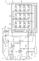
- FIG. 1 is a diagram showing a configuration of a fuel cell system 1 according to a first embodiment of the present invention.
- the fuel cell system 1 is a power generation system that generates power using a fuel cell.
- the fuel cell system 1 includes a hot module 2, a raw fuel supply unit 4, a blower 51, a heating unit 61, a first heat exchanger 71, a second heat exchanger 72, an exhaust gas combustion unit 73, a temperature A measurement unit 74 and a cooling unit 75 are provided.
- the hot module 2 includes a housing 21, a reformer 22, a plurality of fuel cells 23, and a heat supply unit 24.
- the housing 21 is a substantially rectangular parallelepiped housing, for example.
- a partial configuration for example, a housing 21 of the fuel cell system 1 is shown in cross section.
- the inner surface of the housing 21 is formed of a heat insulating material (for example, rock wool) having a relatively high heat insulating property.
- a metal container whose entire inner surface is covered with a heat insulating material is used.
- the reformer 22, the plurality of fuel cells 23, and the heat supply unit 24 are accommodated in the internal space 210 of the housing 21.
- the heat supply unit 24 is mainly used during start-up operation of the fuel cell system 1 described later.
- twelve fuel cells 23 are accommodated in the internal space 210 of the housing 21.
- Each of the plurality of fuel cells 23 is a solid oxide fuel cell (SOFC: Solid Oxide Fuel Cell).
- SOFC Solid Oxide Fuel Cell
- Each fuel cell 23 is, for example, a cell stack in which a plurality of cells (unit cells) not shown are stacked in the vertical direction.
- the outer shape of the fuel cell 23 is, for example, a substantially rectangular parallelepiped shape.
- the number of the plurality of fuel cells 23 accommodated in the housing 21 may be variously changed.
- Fuel gas is supplied to the negative electrode (anode) of each fuel cell 23, and oxidant gas is supplied to the positive electrode (cathode). Thereby, an electrochemical reaction occurs in each fuel cell 23, and power generation is performed. In other words, each fuel cell 23 generates power using fuel gas and oxidant gas.
- the electrochemical reaction in the fuel cell 23 is an exothermic reaction, and the generated heat is used, for example, for heating the reformer 22 where the reforming is an endothermic reaction.
- the power generation by the fuel cell 23 is performed at a high temperature of 600 ° C. to 1000 ° C., for example.
- the fuel gas is, for example, hydrogen gas.
- the oxidant gas is, for example, oxygen.
- the fuel gas may be various gases other than hydrogen gas, and the oxidant gas may be various gases other than oxygen.
- the negative electrode of each fuel cell 23 is connected to the reformer 22 via a fuel gas supply pipe 251 that branches in the housing 21.
- the reformer 22 is connected to the raw fuel supply unit 4 disposed outside the housing 21 via the raw fuel supply pipe 261.
- the raw fuel supply unit 4 supplies raw fuel and steam to the reformer 22.
- the raw fuel supply unit 4 includes a raw fuel supply source 41, an impurity removal unit 42, and a water vapor supply unit 3.
- the impurity removing unit 42 is disposed on the raw fuel supply pipe 261 and removes impurities (for example, sulfur-based impurities and nitrogen-based impurities) from the raw fuel supplied from the raw fuel supply source 41 to the reformer 22.
- the water vapor supply unit 3 includes a water supply unit 31, a water vapor generation unit 32, and a condensing unit 33.
- the water supply unit 31 supplies water to the water vapor generation unit 32.
- the water supply unit 31 includes a water storage unit 311, a pump 312, and a water supply pipe 313.
- the water storage unit 311 is a tank that stores water (for example, pure water).
- the water storage unit 311 is connected to the water vapor generation unit 32 via the water supply pipe 313.
- the pump 312 is provided on the water supply pipe 313 and supplies water stored in the water storage unit 311 to the water vapor generation unit 32.
- the condensing unit 33 condenses water vapor in the exhaust gas during steady operation of the fuel cell system 1 to generate water, and supplies the water to the water vapor generating unit 32 via the water supply unit 31.
- the above-described steady operation means an operation state in which the fuel cell system 1 constantly generates power at a predetermined output.
- the predetermined output is the rated output of the fuel cell system 1 or a constant output less than the rated output, and is hereinafter referred to as “steady operation output”.
- the startup operation means the operating state of the fuel cell system 1 from the time of startup to the steady operation (that is, until the output of the fuel cell 23 reaches the steady operation output and stabilizes).
- the water vapor generation unit 32 heats the water supplied from the water supply unit 31 to generate water vapor.
- the steam generation unit 32 is connected to the raw fuel supply pipe 261 via the steam supply pipe 321.
- the steam supply pipe 321 is connected to the raw fuel supply pipe 261 upstream of the first heat exchanger 71 (specifically, between the first heat exchanger 71 and the impurity removing unit 42).
- the steam from the steam generating unit 32 is supplied to the reformer 22 through the first heat exchanger 71 together with the raw fuel that has passed through the impurity removing unit 42.
- the reformer 22 reforms the raw fuel to generate a reformed gas containing a fuel gas.
- the raw fuel is, for example, a hydrocarbon fuel.
- the raw fuel may be various fuels other than the hydrocarbon fuel.
- the raw fuel for example, LP gas, city gas, natural gas, kerosene, biogas or bioethanol is used.
- the raw fuel is reformed by, for example, a steam reforming method, a partial oxidation reforming method, an autothermal reforming method, or a combination of these reforming methods.
- the city gas which is the raw fuel supplied from the raw fuel supply source 41 by the reformer 22, uses the steam supplied from the steam generation unit 32 to increase the temperature by the steam reforming method.
- a reformed gas containing hydrogen gas as a fuel gas is generated under reforming.
- the reformed gas from the reformer 22 is supplied to each negative electrode of the plurality of fuel cells 23 via the fuel gas supply pipe 251.
- Negative electrode exhaust gas that is gas discharged from each negative electrode of the plurality of fuel cells 23 is collected by the negative electrode exhaust gas discharge pipe 252 and discharged outside the housing 21 via the negative electrode exhaust gas discharge pipe 252.
- the negative electrode exhaust gas includes water vapor generated when hydrogen gas, which is a fuel gas, is used for power generation in the fuel cell 23, and unused fuel gas that has not been used for power generation in the fuel cell 23.
- the fuel gas discharged from the fuel cell 23 in an unused state is referred to as “unused fuel gas”.
- the negative exhaust gas from the plurality of fuel cells 23 is guided to the first heat exchanger 71 through the negative exhaust gas exhaust pipe 252 outside the housing 21.
- the first heat exchanger 71 is disposed on the raw fuel supply pipe 261.
- the raw fuel and steam supplied to the reformer 22 from the raw fuel supply source 41 and the steam generating unit 32 are preheated using the high temperature negative exhaust gas flowing through the negative exhaust gas exhaust pipe 252. Is done.
- the negative electrode exhaust gas that has passed through the first heat exchanger 71 is led to the above-described condensing unit 33 through the negative electrode exhaust gas discharge pipe 252.
- steam in a negative electrode waste gas is condensed and water is produced
- the water generated by the condensing unit 33 is sent to the water storage unit 311 of the water supply unit 31 through the water supply pipe 331, and the water in the water storage unit 311 is supplied to the water vapor generation unit 32 by the pump 312. .
- the negative exhaust gas that has passed through the condensing unit 33 is guided to the exhaust gas combustion unit 73.
- each fuel cell 23 is connected to a blower 51 disposed outside the housing 21 via an oxidant gas supply pipe 253 that branches in the housing 21.
- Air including oxygen which is an oxidant gas, is supplied to each positive electrode of the plurality of fuel cells 23 through the oxidant gas supply pipe 253 by the blower 51.
- the blower 51 is an oxidant gas supply unit that supplies oxidant gas to the fuel cell 23.
- the positive exhaust gas that is the gas discharged from each positive electrode of the plurality of fuel cells 23 is collected by the positive exhaust gas exhaust pipe 254 and is discharged out of the housing 21 through the positive exhaust gas exhaust pipe 254.
- the positive exhaust gas from the plurality of fuel cells 23 is guided to the second heat exchanger 72 through the positive exhaust gas exhaust pipe 254 outside the housing 21.
- the air supplied to each fuel cell 23 is preheated using the high temperature positive exhaust gas flowing through the positive exhaust gas discharge pipe 254.
- the positive exhaust gas exhaust pipe 254 that has passed through the second heat exchanger 72 joins the negative exhaust gas exhaust pipe 252 outside the housing 21 at a junction 731 before (that is, upstream) the exhaust gas combustion unit 73.
- the negative exhaust gas that has passed through the first heat exchanger 71 and the condensing unit 33 and the positive exhaust gas that has passed through the second heat exchanger 72 join together.
- the merged negative electrode exhaust gas and positive electrode exhaust gas are combusted. Thereby, unused fuel gas etc. which are contained in anode exhaust gas are burned.
- the combustion heat generated in the exhaust gas combustion unit 73 may be used, for example, for water heating in the steam generation unit 32, power generation using a turbine or the like, or heating of the reformer 22.
- a catalytic combustor is used as the exhaust gas combustion unit 73.
- the temperature of the exhaust gas combustion unit 73 is continuously measured by the temperature measurement unit 74.
- the cooling unit 75 includes a cooling pipe 751 and a flow rate adjusting unit 752.
- the cooling unit 75 also includes the blower 51 described above.
- the cooling pipe 751 guides the air sent from the blower 51 serving as the oxidant gas supply unit to the exhaust gas combustion unit 73.
- the flow rate adjusting unit 752 is provided on the cooling pipe 751 and adjusts the flow rate of air flowing through the cooling pipe 751.
- the exhaust gas combustion unit 73 By supplying substantially normal temperature air to the exhaust gas combustion unit 73 by the cooling unit 75, the exhaust gas combustion unit 73 is cooled. Further, the temperature of the exhaust gas combustion unit 73 is controlled by adjusting the flow rate of air supplied to the exhaust gas combustion unit 73 by the flow rate adjustment unit 752. Thereby, the temperature of the exhaust gas combustion part 73 can be maintained below a predetermined upper limit temperature.
- the upper limit temperature of the exhaust gas combustion unit 73 is, for example, about 800 degrees.
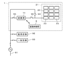
- FIG. 2 is a diagram conceptually showing a state of connection between the power system 91 of the facility where the fuel cell system 1 is installed and the fuel cell system 1.
- the auxiliary machine group 11 of the fuel cell system 1 in the drawing is a general term for a plurality of drive units necessary for the operation of the fuel cell system 1.
- the auxiliary machine group 11 includes the raw fuel supply unit 4 shown in FIG. 1, a blower 51 as an oxidant gas supply unit, and a heating unit 61.
- the auxiliary machinery group 11 may include a configuration other than the raw fuel supply unit 4, the blower 51, and the heating unit 61.
- the housing 21 that houses the plurality of fuel cells 23 is indicated by broken lines, and the configuration of the fuel cell system 1 is surrounded by broken lines.
- the fuel cell system 1 includes an activation control unit 8 that controls the auxiliary machine group 11 and the like.
- FIG. 2 the illustration of the configuration of the fuel cell system 1 excluding the housing 21, the fuel cell 23, the auxiliary machine group 11, the activation control unit 8, and the like is omitted.
- the auxiliary machine group 11 is drawn connected to one fuel cell 23, but in reality, the auxiliary machine group 11 is connected to a plurality of fuel cells 23. The same applies to FIG. 6 described later.
- the important equipment 92 and the general equipment 93 in the figure are equipment of the above facilities where the fuel cell system 1 is installed.
- the important equipment 92 is a group of equipment having a relatively high importance in the facility.
- the general equipment 93 is a facility group of the facility that is not included in the important equipment 92, and is less important than the important equipment 92.
- the important equipment 92 differs depending on the facility where the fuel cell system 1 is installed. For example, in a supermarket or a convenience store, the refrigeration equipment is included in the important equipment 92.
- equipment related to a production line is included in the important equipment 92 in a manufacturing factory for equipment and the like.
- the important equipment 92 in the manufacturing plant may include air conditioning equipment. In hospitals and the like, lighting facilities and air conditioning facilities are included in the important facilities 92. Communication equipment such as a telephone is included in important equipment 92 in various facilities.
- the auxiliary machine group 11, the important equipment 92, and the general equipment 93 are connected to the plurality of fuel cells 23 of the fuel cell system 1 and the power system 91 of the facility.
- the power output from the plurality of fuel cells 23 is preferentially supplied to the auxiliary machinery group 11 and the important equipment 92, for example.
- the electric power output from the plurality of fuel cells 23 is larger than the sum of the auxiliary equipment driving power required for driving the auxiliary equipment group 11 and the important equipment driving power required for driving the important equipment 92.
- surplus power obtained by subtracting auxiliary machine drive power and important equipment drive power from the power from the plurality of fuel cells 23 is supplied to the general equipment 93.
- the general equipment 93 may also be supplied with power from the facility power system 91.
- the fuel Stopping operation of the battery system 1 can be prevented or suppressed.
- the important equipment driving power necessary for driving the important equipment 92 is also covered by the fuel cell system 1, even if a power failure occurs in the power system 91, the important equipment 92 of the facility is stopped. Can be prevented or suppressed.
- the start-up operation of the fuel cell system 1 is to change the state of the fuel cell system 1 from a stopped state to a steady operation state in which power generation is regularly performed with a steady operation output.
- the heating unit 61 and the water supply unit 31 of the water vapor supply unit 3 are used.
- power is supplied to the auxiliary machinery group 11 (see FIG. 2) of the fuel cell system 1 from the power system 91 of the facility where the fuel cell system 1 is installed. Electric power is also supplied from the power system 91 to the important equipment 92 and the general equipment 93 of the facility.
- the heating unit 61 heats the inside of the housing 21 during the start-up operation.
- the heating unit 61 is connected to the raw fuel supply source 41 through the impurity removing unit 42 by the starting raw fuel supply pipe 262.
- the heating unit 61 is also connected to the blower 51 via the starting gas supply pipe 263.
- a raw fuel for example, LP gas, city gas, natural gas, kerosene, biogas, or bioethanol
- a gas for example, oxidant gas from the blower 51
- a temperature rising gas that is a high-temperature gas is generated using air.
- a gas burner is used as the heating unit 61, and raw material fuel is combusted in the heating unit 61, thereby generating a temperature rising gas.
- the hot temperature rising gas generated by the heating unit 61 is supplied to the heat supply unit 24 in the housing 21 via the temperature rising gas supply pipe 264, and from the heat supply unit 24 to the internal space 210 of the housing 21. Supplied.
- the temperature raising gas is continuously supplied from the heat supply unit 24 to the internal space 210, whereby the reformer 22 and the plurality of fuel cells 23 inside the housing 21 are heated to raise the temperature.
- Step S11 When the temperature of the fuel cell 23 is raised to a predetermined temperature (for example, about 600 ° C. to 1000 ° C.), the temperature raising process in step S11 is completed.
- the temperature raising step takes about 8 to 15 hours, for example.
- the temperature rising gas from the heating unit 61 is continuously supplied into the housing 21 in order to maintain the temperature in the housing 21 even after the temperature rising process is finished.
- the water in the water storage unit 311 is supplied to the steam generation unit 32 by the pump 312 as described above.
- the water vapor generation unit 32 the water supplied from the water supply unit 31 is heated to generate water vapor.
- the supply of raw fuel is started from the raw fuel supply source 41.
- the raw fuel from the raw fuel supply source 41 and the steam from the steam generation unit 32 are supplied to the reformer 22 through the first heat exchanger 71.
- the raw fuel is steam reformed by the reformer 22, so that a reformed gas containing a fuel gas is generated and supplied to the negative electrodes of the plurality of fuel cells 23.
- air containing an oxidant gas is supplied from the blower 51 to the positive electrodes of the plurality of fuel cells 23. Thereby, power generation by the plurality of fuel cells 23 is started.
- step S12 extraction of current from the plurality of fuel cells 23 (that is, load removal) is started (step S12). Further, the reformer 22 is further heated by heat generated from the plurality of fuel cells 23 during power generation.
- the negative electrode exhaust gas from the plurality of fuel cells 23 is led to the condensing unit 33 as described above.
- the water generated from the negative electrode exhaust gas in the condensing unit 33 is supplied to the water vapor generating unit 32 via the water supply unit 31.
- the negative electrode exhaust gas that has passed through the condensing unit 33 is guided to the exhaust gas combustion unit 73 together with the positive electrode exhaust gas, and unused fuel gas contained in the negative electrode exhaust gas is combusted in the exhaust gas combustion unit 73.
- the amount of raw fuel supplied from the raw fuel supply unit 4 to the reformer 22 per unit time is increased stepwise by control by the start control unit 8 (see FIG. 2).
- the amount of fuel gas supplied to the plurality of fuel cells 23 per unit time is increased stepwise.
- the output from the fuel cell 23 (that is, the current taken from the fuel cell 23 during load removal) is also increased stepwise. Thereby, it is possible to prevent the state of the fuel cell 23 from changing suddenly. It is also possible to prevent a large amount of unused fuel gas from being burned in the exhaust gas combustion unit 73 and causing the temperature of the exhaust gas combustion unit 73 to become excessively high.
- the above-described stepwise load removal is performed until the outputs from the plurality of fuel cells 23 reach the above-described steady operation output and stabilize, that is, until the fuel cell system 1 enters the steady operation state. Will continue.
- steady operation of the fuel cell system 1 is started and the above-described thermal self-sustainment is established, generation of the temperature rising gas in the heating unit 61 and supply of the temperature rising gas from the heat supply unit 24 to the internal space 210 are stopped. .
- FIG. 4 is a diagram illustrating a change in the amount of raw fuel supplied and a change in the output from the plurality of fuel cells 23 in the start-up operation of the fuel cell system 1.
- the horizontal axis of FIG. 4 shows the elapsed time from the start of load taking.
- the vertical axis in FIG. 4 indicates the supply amount of raw fuel from the raw fuel supply unit 4 per unit time (hereinafter also simply referred to as “supply amount”) and the total output from the plurality of fuel cells 23.
- supply amount the supply amount of raw fuel from the raw fuel supply unit 4 per unit time
- the numerical value attached to the vertical axis indicates the total output from the plurality of fuel cells 23 (hereinafter also simply referred to as “output”).
- a solid line 101 and a broken line 102 in FIG. 4 indicate a change in the amount of raw fuel supplied and a change in the output from the plurality of fuel cells 23, respectively.
- the raw fuel supply unit 4 is controlled by the start control unit 8, so that the amount of raw fuel supplied from the raw fuel supply unit 4 is stepped. Increase. Specifically, the supply amount of the raw fuel from the raw fuel supply unit 4 is within a range equal to or less than the steady supply amount corresponding to the steady operation output (that is, the supply amount of the raw fuel during the steady operation of the fuel cell system 1). A plurality of set supply amounts are set in advance in the start control unit 8 step by step.
- the start control unit 8 controls the raw fuel supply unit 4
- the supply amount of the raw fuel from the raw fuel supply unit 4 is maintained at an initial supply amount that is a minimum set supply amount among a plurality of set supply amounts. The Then, after a predetermined time has elapsed from the start of supply of raw fuel, load removal of the plurality of fuel cells 23 is started. As a result, the output from the plurality of fuel cells 23 increases, and after reaching the output corresponding to the initial supply amount, the supply amount of the raw fuel from the raw fuel supply unit 4 is set to the next largest supply after the initial supply amount. Increased to quantity.
- the increase rate of the output from the plurality of fuel cells 23 is, for example, 1 A (ampere) / second. Further, the time required for the output to reach the output corresponding to the initial supply amount from the start of the increase in output from the plurality of fuel cells 23 is, for example, within one minute.
- the initial supply amount is the first supply amount of raw fuel corresponding to the above-described auxiliary machine drive power (that is, the supply amount of raw fuel when the outputs from the plurality of fuel cells 23 are equal to the auxiliary drive power). More than the supply amount.
- the auxiliary machine drive power is, for example, 9 kW.
- auxiliary machine driving power is indicated by a two-dot chain line 103.
- the output from the plurality of fuel cells 23 corresponding to the initial supply amount is 9 kW, and the steady operation output is 20 kW.
- Outputs corresponding to a plurality of set supply amounts other than the initial supply amount are 12 kW, 15 kW, and 18 kW.
- outputs corresponding to a plurality of set supply amounts other than the initial supply amount are set at substantially equal intervals. Further, the initial supply amount is larger than the difference between two adjacent set supply amounts in the plurality of set supply amounts described above.
- the supply amount of the raw fuel from the raw fuel supply unit 4 is maintained at one set supply amount in order from the smallest of the plurality of set supply amounts, and the output from the plurality of fuel cells 23 After reaching an output corresponding to one set supply amount (hereinafter referred to as “set output”), it is repeated that the set supply amount is increased to the next largest set supply amount. Then, when the supply amount of the raw fuel from the raw fuel supply unit 4 reaches the steady supply amount, and the outputs from the plurality of fuel cells 23 reach the steady operation output and stabilize, the start-up operation of the fuel cell system 1 is performed. Ends.
- the supply amount of the raw fuel is maintained at the one set supply amount for a predetermined time.
- the temperatures of the plurality of fuel cells 23, the outputs from the plurality of fuel cells 23, and the like are further stabilized at values corresponding to the one set supply amount.
- the time for maintaining the supply amount of the raw fuel at each set supply amount is, for example, about 10 minutes.
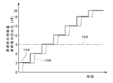
- FIG. 5 is a diagram showing a change in the amount of raw fuel supplied and a change in the output from the fuel cell in the startup operation of the fuel cell system of the comparative example.
- the horizontal and vertical axes in FIG. 5 are the same as the horizontal and vertical axes in FIG.
- a solid line 104, a broken line 105, and a two-dot chain line 106 in FIG. 5 respectively indicate a change in the amount of raw fuel supplied, a change in output from a plurality of fuel cells, and an auxiliary drive power in the fuel cell system of the comparative example. .
- the supply amount of the raw fuel increases stepwise so as to be sequentially equal to the plurality of set supply amounts.
- the outputs of the fuel cells corresponding to a plurality of set supply amounts are set at substantially equal intervals.
- the steady operation output is 20 kW, and the outputs corresponding to a plurality of set supply amounts are 3 kW, 6 kW, 9 kW, 12 kW, 15 kW, and 18 kW.
- the initial supply amount of the raw fuel from the raw fuel supply unit 4 is not less than the first supply amount that is the supply amount of the raw fuel corresponding to the auxiliary machine drive power. Therefore, the outputs from the plurality of fuel cells 23 can reach the output exceeding the auxiliary drive power in a short time. Therefore, when a power failure occurs in the power system 91 during the start-up operation of the fuel cell system 1, even if the supply amount of raw fuel at the time of the power failure is the initial supply amount, a plurality of fuel cells are controlled by the control by the start control unit 8. Power is supplied from 23 to the auxiliary machine group 11, and the driving of the auxiliary machine group 11 can be continued. Specifically, the switches 94 and 95 in FIG. 2 are switched from on to off, and the switch 96 is switched from off to on.
- the fuel cell system 1 since it is possible to promptly switch to the self-sustained operation in the event of a power failure during the start-up operation, it is possible to prevent the fuel cell system 1 during the start-up operation from being stopped. As a result, after the power system 91 is restored, the auxiliary machine group 11 can be reconnected to the power system 91 and the start-up operation can be resumed promptly.
- the cooling unit 75 is based on the output from the temperature measurement unit 74 (that is, the temperature of the exhaust gas combustion unit 73). Controlled by the activation control unit 8, the exhaust gas combustion unit 73 is cooled as necessary. Thereby, the temperature of the exhaust gas combustion part 73 is maintained below a predetermined upper limit temperature. As a result, it is possible to prevent the exhaust gas combustion unit 73 from stopping at an excessively high temperature when the fuel cell system 1 is started up.
- the cooling unit 75 includes the cooling pipe 751 and the flow rate adjusting unit 752.
- the cooling pipe 751 guides the oxidant gas sent from the blower 51 to the exhaust gas combustion unit 73.
- the flow rate adjusting unit 752 is provided on the cooling pipe 751 to adjust the flow rate of the oxidant gas.
- the structure of the fuel cell system 1 can be simplified by using the blower 51 that is an oxidant gas supply unit that supplies the oxidant gas to the fuel cell 23 for cooling the exhaust gas combustion unit 73. .
- the flow rate of the oxidant gas supplied from the blower 51 to the fuel cell 23 is higher than that during steady operation of the fuel cell system 1 (that is, the raw fuel supply amount). Less than the steady supply rate). For this reason, the blower 51 can be used for cooling the exhaust gas combustion unit 73 without increasing the capacity of the blower 51 (that is, the rated flow rate).
- FIG. 6 shows a fuel cell system 1a according to the second embodiment of the present invention.
- FIG. 6 is a diagram conceptually showing a state of connection between the power system 91 of the facility where the fuel cell system 1a is installed and the fuel cell system 1a, as in FIG.
- the fuel cell system 1a further includes a gas cylinder 52 and an uninterruptible power supply 53 in addition to the components of the fuel cell system 1 described above.
- the gas cylinder 52 stores air containing oxygen which is an oxidant gas. In the gas cylinder 52, only the oxidant gas may be stored.
- the gas cylinder 52 is depicted as being connected to one fuel cell 23, but actually, the gas cylinder 52 is connected to a plurality of fuel cells 23.
- the other configuration of the fuel cell system 1a is substantially the same as that of the fuel cell system 1 shown in FIG. 1, and the corresponding components are denoted by the same reference numerals in the following description.
- the connection between the fuel cell system 1a and the power system 91 and the like is the same as the connection between the fuel cell system 1 and the power system 91 and the like shown in FIG.
- the start-up operation of the fuel cell system 1a is substantially the same as the start-up operation of the fuel cell system 1 described above.
- power is supplied from the plurality of fuel cells 23 to the auxiliary machine group 11 under the control of the start control unit 8 as described above, and the auxiliary machine group 11 driving can be continued.
- the blower 51 (see FIG. 1), which is an oxidant gas supply unit included in the auxiliary machine group 11, is stopped, and oxidant gas (including air) is supplied from the gas cylinder 52 to the plurality of fuel cells 23. Further, power is supplied from the uninterruptible power supply 53 to the auxiliary machine group 11 other than the blower 51.
- the auxiliary machinery group 11 other than the blower 51 is a configuration in which the blower 51 is excluded from the configuration included in the auxiliary machinery group 11, and includes, for example, the raw fuel supply unit 4 and the heating unit 61 (see FIG. 1).
- the power supply source to the auxiliary machine group 11 can be stably switched from the power system 91 to the plurality of fuel cells 23 when a power failure occurs during the start-up operation.
- the capacity of the uninterruptible power supply 53 that temporarily supplies power to the auxiliary machine group 11 is stopped. That is, the rated output) can be reduced.
- the exhaust gas combustion unit 73 rises during the switching of the power supply source to the auxiliary machine group 11 described above, the exhaust gas is discharged from the gas cylinder 52 via the cooling pipe 751 as necessary.
- the temperature of the exhaust gas combustion unit 73 may be maintained below a predetermined upper limit temperature.
- the gas cylinder 52 is also included in the cooling unit 75.
- the fuel cell systems 1 and 1a when a power failure occurs in the power system 91 during the start-up operation, power is supplied from the plurality of fuel cells 23 to the auxiliary machine group 11, but the auxiliary machine group 11 is supplied with power.
- power may be supplied from the plurality of fuel cells 23 to the important equipment 92 of the facility.
- the important equipment driving power required for driving the important equipment 92 differs for each facility, and even one facility may differ depending on the season, day of the week, time zone, and the like. For this reason, the important equipment drive power of the facility where the fuel cell systems 1 and 1a are installed is acquired in advance and stored in the activation control unit 8 of the fuel cell systems 1 and 1a.
- the important equipment driving power for each season, day of the week, time zone, etc. is acquired and stored in the activation control unit 8.
- a sensor or the like that continuously measures the important equipment driving power is provided in the facility, the important equipment driving power is continuously acquired in advance in preparation for a power failure, and the measured value of the important equipment driving power is sent to the activation control unit 8. It may be memorized.
- the output from the fuel cell 23 that is being loaded is compared with the sum of the auxiliary machine drive power and the important equipment drive power. .
- the fuel cell 23 sends the auxiliary machine group 11 and the important equipment 92 to the control by the start control unit 8. Power is supplied. Thereby, even at the time of a power failure of the electric power system 91, it can suppress that the fuel cell system 1 and 1a and the important equipment 92 of a facility during start-up operation stop. In other words, the fuel cell system 1, 1 a and the important facility 92 can be operated independently.
- the supply amount of the raw fuel from the raw fuel supply unit 4 during the power system 91 is interrupted.
- the raw fuel supply amount corresponding to the sum of the auxiliary machine drive power and the important equipment drive power is reduced to approximately equal to the supply amount.
- the supply amount of the raw fuel from the raw fuel supply unit 4 is the raw material corresponding to the sum of the auxiliary machine driving power and the important equipment driving power. It is preferable that the fuel supply amount be about 105%.
- the power supply from the plurality of fuel cells 23 to the auxiliary machinery group 11 is maintained, and the plurality of fuel cells 23 to the important equipment 92 is maintained. The power supply is stopped.
- the initial supply amount of the raw fuel in the start-up operation of the fuel cell systems 1 and 1a is equal to the first supply amount that is the supply amount of the raw fuel corresponding to the auxiliary machine drive power, but the initial supply amount is the first supply amount.
- the initial supply amount may be equal to or greater than the second supply amount that is the supply amount of raw fuel corresponding to the sum of the auxiliary machine drive power and the important equipment drive power.
- the initial supply amount of the raw fuel supplied from the raw fuel supply unit 4 is an unused fuel that can be combusted in the exhaust gas combustion unit 73. It is preferable that the feed amount of the raw fuel corresponding to the upper limit amount of gas be less than or equal to. In other words, it is preferable that the amount of fuel gas generated from the raw fuel supplied at the initial supply amount be equal to or less than the upper limit amount of unused fuel gas combustible in the exhaust gas combustion unit 73.
- the important equipment driving power of the facility where the fuel cell system 1, 1 a is installed is acquired in advance and stored in the activation control unit 8 of the fuel cell system 1, 1 a.
- the initial supply of the raw fuel supplied from the raw fuel supply part 4 The amount is determined by the activation control unit 8 in a range not less than the second supply amount and not more than the supply amount corresponding to the upper limit amount.
- the activation control unit 8 determines the initial supply amount in a range not less than the first supply amount and not more than the supply amount corresponding to the upper limit amount.
- the fuel cell system 1, 1 a does not necessarily include a plurality of fuel cells 23, and the number of fuel cells 23 accommodated in the housing 21 may be one.
- the start control unit 8 sets the output from the temperature measurement unit 74 in the same manner as described above while the raw fuel is supplied at a set supply amount other than the initial supply amount. Based on the control of the cooling unit 75, the temperature of the exhaust gas combustion unit 73 may be maintained below a predetermined upper limit temperature. Thereby, in the start-up operation of the fuel cell systems 1 and 1a, it is possible to suppress the exhaust gas combustion unit 73 from being stopped due to an excessively high temperature.
- the cooling unit 75 does not necessarily need to use the air sent from the blower 51 to cool the exhaust gas combustion unit 73.
- the cooling unit 75 may cool the exhaust gas combustion unit 73 using, for example, water or water vapor.
- the heating unit 61 may be connected to another raw fuel supply source and another blower different from the raw fuel supply source 41 and the blower 51.
- the raw fuel supplied from the other raw fuel supply source to the heating unit 61 may be of a different type from the raw fuel supplied from the raw fuel supply source 41 to the reformer 22.
- the heating unit 61 is not necessarily a gas burner.
- a catalytic combustor or an electric heater may be used as the heating unit 61.
- the water vapor contained in the negative electrode exhaust gas is taken out as water by the condensing unit 33 and then supplied to the water vapor generating unit 32 through the water supply unit 31.
- a part of the negative electrode exhaust gas may be supplied to the reformer 22 in a gaseous state. Even in this case, it is possible to realize water self-sustained operation during steady operation.
- the temperature rising gas may be continuously supplied from the heating unit 61 to the internal space 210 of the housing 21.
- the water self-sustained operation is not necessarily performed during the steady operation.
- the water supplied to the storage unit 311 may be continuously supplied to the steam generation unit 32.
Landscapes
- Engineering & Computer Science (AREA)
- Chemical & Material Sciences (AREA)
- Life Sciences & Earth Sciences (AREA)
- Manufacturing & Machinery (AREA)
- Sustainable Development (AREA)
- Sustainable Energy (AREA)
- Chemical Kinetics & Catalysis (AREA)
- Electrochemistry (AREA)
- General Chemical & Material Sciences (AREA)
- Combustion & Propulsion (AREA)
- Fuel Cell (AREA)
Abstract
燃料電池システム(1)では、原燃料供給部からの原燃料の初期供給量が、補機駆動電力に対応する原燃料の供給量である第1供給量以上であるため、複数の燃料電池(23)からの出力が、補機駆動電力以上の出力に短時間で到達することができる。したがって、燃料電池システム(1)の起動運転時に電力系統(91)において停電が発生した場合、当該停電時の原燃料の供給量が初期供給量であっても、起動制御部(8)による制御により、複数の燃料電池(23)から補機群(11)に電力が供給され、補機群(11)の駆動を継続することができる。このように、燃料電池システム(1)では、起動運転時の停電に際して速やかに自立運転に切り替えることができるため、起動運転中の燃料電池システム(1)が停止することを抑制することができる。
Description
本発明は、燃料電池システムに関する。
従来、燃料電池を利用して発電を行う様々な燃料電池システムが提案されている(例えば、特開2014-182884号公報(文献1)および特開2015-186408号公報(文献2))。固体酸化物形の燃料電池を用いた燃料電池システムでは、起動運転の際に、燃料電池を約600℃~1000℃の高温まで昇温する必要がある。当該燃料電池システム、特に、業務用または産業用の燃料電池システムでは、燃料電池の昇温は、ガスバーナ等を利用して比較的長時間(例えば、8~15時間)かけて行われる。燃料電池の昇温が終了すると、ガスバーナ等による燃料電池の加熱が継続された状態で、燃料電池に対する燃料ガスおよび酸化剤ガスの供給が開始され、燃料電池からの電流の取り出し(すなわち、負荷取り)が開始される。
一般的に、固体酸化物形の燃料電池は急激な状態変化に対する耐久性があまり高くないため、負荷取りの開始時に多量の燃料ガスおよび酸化剤ガスを燃料電池に供給することは好ましくない。また、仮に、負荷取りの開始時に定格出力に対応する量の燃料ガスおよび酸化剤ガスを燃料電池に供給したとすると、燃料電池で発電に利用される燃料ガスが少ないため、燃料電池を通過した未利用の燃料ガスを燃焼させる燃焼部の温度が過剰に高くなるおそれがある。そこで、燃料電池システムの負荷取りでは、例えば、比較的少量の燃料ガスおよび酸化剤ガスを燃料電池に供給して燃料電池からの出力が安定するまで待機した後、燃料ガスおよび酸化剤ガスの供給量を段階的に増加させることが繰り返される。これにより、燃料電池からの出力も段階的に増加し、比較的長時間(例えば、約1時間)かけて定格出力に到達する。
ところで、上述の燃料電池システムの負荷取り中に、燃料電池システムが設置される施設の電力系統において停電が発生すると、燃料電池に燃料ガスおよび酸化剤ガスを供給する機構、並びに、燃料電池を加熱するガスバーナ等が停止し、燃料電池システムが停止する。その結果、長時間かかる燃料電池システムの起動運転(すなわち、燃料電池の昇温および負荷取り)をやり直す必要がある。文献1および文献2では、燃料電池システムの定常運転中に施設の電力系統において停電が発生した場合の燃料電池システムの制御方法は提案されているが、燃料電池システムの起動運転時の停電については考慮されていない。
本発明は、燃料電池システムに向けられており、燃料電池システムの起動運転時に施設の電力系統において停電が発生した場合であっても、燃料電池システムが停止することを抑制することを目的としている。
本発明に係る燃料電池システムは、原燃料を改質して燃料ガスを生成する改質器と、前記燃料ガスおよび酸化剤ガスを用いて発電を行う固体酸化物形の燃料電池と、内部空間に前記改質器および前記燃料電池を収容するハウジングと、前記改質器に前記原燃料を供給する原燃料供給部と、前記燃料電池に前記酸化剤ガスを供給する酸化剤ガス供給部と、前記燃料電池から未利用の状態にて排出される未利用燃料ガスを燃焼させる排ガス燃焼部と、前記原燃料供給部を制御し、前記燃料電池の出力が定常運転出力に到達するまでの起動運転の際に、前記原燃料供給部からの前記原燃料の供給量を段階的に増大させる起動制御部と、前記起動運転の際に前記ハウジングの内部を加熱する加熱部とを備える。前記起動運転時における前記原燃料供給部からの前記原燃料の供給量について、前記定常運転出力に対応する定常供給量以下の範囲で、複数の設定供給量が予め段階的に設定されている。前記起動制御部が前記原燃料供給部を制御することにより、前記原燃料供給部からの前記原燃料の供給量を、前記複数の設定供給量のうち小さい方から順に一の設定供給量に維持し、前記燃料電池からの出力が前記一の設定供給量に対応する設定出力に到達した後、前記一の設定供給量の次に大きい設定供給量へと増大することを繰り返す。前記複数の設定供給量のうち最小の設定供給量である初期供給量が、前記原燃料供給部と前記酸化剤ガス供給部と前記加熱部とを含む補機群の駆動に必要な補機駆動電力に対応する前記原燃料の供給量である第1供給量以上である。前記起動運転の際、前記燃料電池システムが設置される施設の電力系統から前記補機群に電力が供給される。前記起動運転時に前記電力系統において停電が発生した場合、前記起動制御部による制御により、前記燃料電池から前記補機群に電力が供給される。これにより、燃料電池システムの起動運転時に施設の電力系統において停電が発生した場合であっても、燃料電池システムが停止することを抑制することができる。
本発明の一の好ましい実施の形態では、前記燃料電池システムは、前記酸化剤ガスを貯溜するガスボンベと、無停電電源装置とをさらに備える。前記起動運転時の停電発生の際に、前記補機群への電力の供給源が前記電力系統から前記燃料電池へと切り替えられる間、前記酸化剤ガス供給部が停止されて前記ガスボンベから前記燃料電池に前記酸化剤ガスが供給され、前記無停電電源装置から前記酸化剤ガス供給部以外の前記補機群に電力が供給される。
本発明の他の好ましい実施の形態では、前記燃料電池システムが設置される前記施設の重要設備の駆動に必要な重要設備駆動電力が予め取得され、前記起動運転時に前記電力系統において停電が発生した際に、前記燃料電池からの出力が前記補機駆動電力と前記重要設備駆動電力との合計以上である場合、前記起動制御部による制御により、前記燃料電池から前記補機群および前記重要設備に電力が供給される。
本発明の他の好ましい実施の形態では、前記燃料電池システムが設置される前記施設の重要設備の駆動に必要な重要設備駆動電力が予め取得され、前記補機駆動電力と前記重要設備駆動電力との合計に対応する前記原燃料の供給量である第2供給量が、前記排ガス燃焼部にて燃焼可能な前記未利用燃料ガスの上限量に対応する供給量以下である場合、前記初期供給量が前記第2供給量以上かつ前記上限量に対応する供給量以下とされ、前記第2供給量が前記上限量に対応する供給量よりも大きい場合、前記初期供給量が前記第1供給量以上かつ前記上限量に対応する供給量以下とされる。
本発明の他の好ましい実施の形態では、前記燃料電池システムは、前記排ガス燃焼部の温度を測定する温度測定部と、前記排ガス燃焼部を冷却する冷却部とをさらに備える。前記起動運転において前記原燃料が前記初期供給量にて供給されている間、前記起動制御部が、前記温度測定部からの出力に基づいて前記冷却部を制御することにより、前記排ガス燃焼部の温度を所定の上限温度以下に維持する。
より好ましくは、前記冷却部が、前記酸化剤ガス供給部から送出された前記酸化剤ガスを前記排ガス燃焼部へと導く冷却用配管と、前記冷却用配管上に設けられて前記酸化剤ガスの流量を調節する流量調節部とを備える。
上述の目的および他の目的、特徴、態様および利点は、添付した図面を参照して以下に行うこの発明の詳細な説明により明らかにされる。
図1は、本発明の第1の実施の形態に係る燃料電池システム1の構成を示す図である。燃料電池システム1は、燃料電池を用いて発電を行う発電システムである。燃料電池システム1は、ホットモジュール2と、原燃料供給部4と、ブロワ51と、加熱部61と、第1熱交換器71と、第2熱交換器72と、排ガス燃焼部73と、温度測定部74と、冷却部75とを備える。
ホットモジュール2は、ハウジング21と、改質器22と、複数の燃料電池23と、熱供給部24とを備える。ハウジング21は、例えば、略直方体状の筐体である。図1では、燃料電池システム1の一部の構成(例えば、ハウジング21)を断面にて示す。ハウジング21の内面は、断熱性が比較的高い断熱材料(例えば、ロックウール)により形成される。ハウジング21としては、例えば、金属製のコンテナの内面全体を断熱材料により覆ったものが利用される。
ハウジング21の内部空間210には、改質器22、複数の燃料電池23および熱供給部24が収容される。熱供給部24は、後述する燃料電池システム1の起動運転時に主に利用される。図1に示す例では、ハウジング21の内部空間210には、12個の燃料電池23が収容される。複数の燃料電池23はそれぞれ、固体酸化物形燃料電池(SOFC:Solid Oxide Fuel Cell)である。各燃料電池23は、例えば、図示省略の複数のセル(単電池)が上下方向に積層されたセルスタックである。燃料電池23の外形は、例えば、略直方体状である。ハウジング21内に収容される複数の燃料電池23の数は、様々に変更されてよい。
各燃料電池23の負極(アノード)には燃料ガスが供給され、正極(カソード)には酸化剤ガスが供給される。これにより、各燃料電池23において電気化学反応が生じ、発電が行われる。換言すれば、各燃料電池23は、燃料ガスおよび酸化剤ガスを用いて発電を行う。燃料電池23における電気化学反応は発熱反応であり、発生した熱は、例えば、吸熱反応である改質が行われる改質器22の加熱等に利用される。燃料電池23による発電は、例えば600℃~1000℃の高温下にて行われる。燃料ガスは、例えば水素ガスである。酸化剤ガスは、例えば酸素である。燃料ガスは、水素ガス以外の様々なガスであってよく、酸化剤ガスも、酸素以外の様々なガスであってよい。
各燃料電池23の負極は、ハウジング21内にて分岐する燃料ガス供給管251を介して改質器22に接続される。改質器22は、原燃料供給管261を介して、ハウジング21外に配置される原燃料供給部4に接続される。原燃料供給部4は、改質器22に原燃料および水蒸気を供給する。原燃料供給部4は、原燃料供給源41と、不純物除去部42と、水蒸気供給部3とを備える。不純物除去部42は、原燃料供給管261上に配置され、原燃料供給源41から改質器22へと供給される原燃料から不純物(例えば、硫黄系不純物および窒素系不純物)を除去する。
水蒸気供給部3は、水供給部31と、水蒸気生成部32と、凝縮部33とを備える。水供給部31は、水蒸気生成部32に水を供給する。具体的には、水供給部31は、水貯溜部311と、ポンプ312と、水供給管313とを備える。水貯溜部311は、水(例えば、純水)を貯溜するタンクである。水貯溜部311は、水供給管313を介して、水蒸気生成部32に接続される。ポンプ312は、水供給管313上に設けられ、水貯溜部311に貯溜されている水を水蒸気生成部32へと供給する。
凝縮部33は、燃料電池システム1の定常運転時に排ガス中の水蒸気を凝縮して水を生成し、水供給部31を介して水蒸気生成部32に供給する。上述の定常運転とは、燃料電池システム1が所定の出力にて定常的に発電を行っている運転状態を意味する。当該所定の出力は、燃料電池システム1の定格出力、または、定格出力未満の一定の出力であり、以下、「定常運転出力」という。また、起動運転とは、起動時から当該定常運転に至るまで(すなわち、燃料電池23の出力が定常運転出力に到達して安定するまで)の燃料電池システム1の運転状態を意味する。水蒸気生成部32は、水供給部31から供給される水を加熱して水蒸気を生成する。水蒸気生成部32は、水蒸気供給管321を介して原燃料供給管261に接続される。水蒸気供給管321は、第1熱交換器71よりも上流において(具体的には、第1熱交換器71と不純物除去部42との間において)原燃料供給管261に接続される。水蒸気生成部32からの水蒸気は、不純物除去部42を通過した原燃料と共に、第1熱交換器71を通過して改質器22へと供給される。
改質器22は、原燃料を改質して燃料ガスを含む改質ガスを生成する。原燃料は、例えば、炭化水素系燃料である。原燃料は、炭化水素系燃料以外の様々な燃料であってもよい。原燃料としては、例えば、LPガス、都市ガス、天然ガス、灯油、バイオガスまたはバイオエタノール等が利用される。改質器22では、例えば、水蒸気改質法、部分酸化改質法または自己熱改質法、あるいは、これらの改質法の組み合わせ等により原燃料の改質が行われる。図1に示す例では、改質器22により、原燃料供給源41から供給された原燃料である都市ガスが、水蒸気生成部32から供給された水蒸気を利用して、水蒸気改質法により高温下にて改質され、燃料ガスである水素ガスを含む改質ガスが生成される。改質器22からの改質ガスは、燃料ガス供給管251を介して複数の燃料電池23のそれぞれの負極へと供給される。
複数の燃料電池23のそれぞれの負極から排出されるガスである負極排ガスは、負極排ガス排出管252により集められ、負極排ガス排出管252を介してハウジング21外に排出される。負極排ガスには、燃料ガスである水素ガスが燃料電池23における発電に使用されることにより生成される水蒸気、および、燃料電池23における発電に利用されなかった未利用の燃料ガス等が含まれる。以下の説明では、燃料電池23から未利用の状態にて排出される燃料ガスを「未利用燃料ガス」という。
複数の燃料電池23からの負極排ガスは、ハウジング21外において負極排ガス排出管252により第1熱交換器71へと導かれる。第1熱交換器71は、原燃料供給管261上に配置されている。第1熱交換器71では、負極排ガス排出管252を流れる高温の負極排ガスを利用して、原燃料供給源41および水蒸気生成部32から改質器22に供給される原燃料および水蒸気が予備加熱される。
一方、第1熱交換器71を通過した負極排ガスは、負極排ガス排出管252により上述の凝縮部33へと導かれる。凝縮部33では、負極排ガス中の水蒸気が凝縮されて水が生成される。凝縮部33により生成された水は、水供給管331を介して水供給部31の水貯溜部311に送られ、水貯溜部311内の水がポンプ312により水蒸気生成部32へと供給される。凝縮部33を通過した負極排ガスは、排ガス燃焼部73へと導かれる。
各燃料電池23の正極は、ハウジング21内にて分岐する酸化剤ガス供給管253を介して、ハウジング21外に配置されるブロワ51に接続される。ブロワ51により、酸化剤ガスである酸素を含む空気が、酸化剤ガス供給管253を介して複数の燃料電池23のそれぞれの正極に供給される。すなわち、ブロワ51は、燃料電池23に酸化剤ガスを供給する酸化剤ガス供給部である。
複数の燃料電池23のそれぞれの正極から排出されるガスである正極排ガスは、正極排ガス排出管254により集められ、正極排ガス排出管254を介してハウジング21外へと排出される。複数の燃料電池23からの正極排ガスは、ハウジング21外において正極排ガス排出管254により第2熱交換器72へと導かれる。第2熱交換器72では、正極排ガス排出管254を流れる高温の正極排ガスを利用して、各燃料電池23に供給される空気が予備加熱される。
第2熱交換器72を通過した正極排ガス排出管254は、排ガス燃焼部73よりも手前(すなわち、上流側)の合流点731において、ハウジング21外にて負極排ガス排出管252と合流する。合流点731では、第1熱交換器71および凝縮部33を通過した負極排ガスと、第2熱交換器72を通過した正極排ガスとが合流する。排ガス燃焼部73では、合流後の負極排ガスおよび正極排ガスが燃焼される。これにより、負極排ガスに含まれる未利用燃料ガス等が燃焼される。排ガス燃焼部73にて発生する燃焼熱は、例えば、水蒸気生成部32における水の加熱、タービン等を利用した発電、または、改質器22の加熱等に利用されてもよい。排ガス燃焼部73としては、例えば、触媒燃焼器が利用される。
燃料電池システム1では、排ガス燃焼部73の温度が温度測定部74により継続的に測定される。排ガス燃焼部73の温度が過剰に高くなった場合には、冷却部75により排ガス燃焼部73が冷却される。図1に示す例では、冷却部75は、冷却用配管751と、流量調節部752とを備える。また、冷却部75は、上述のブロワ51も含む。冷却用配管751は、酸化剤ガス供給部であるブロワ51から送出された空気を排ガス燃焼部73へと導く。流量調節部752は、冷却用配管751上に設けられ、冷却用配管751を流れる空気の流量を調節する。冷却部75により略常温の空気が排ガス燃焼部73に供給されることにより、排ガス燃焼部73が冷却される。また、流量調節部752により、排ガス燃焼部73に供給される空気の流量が調節されることにより、排ガス燃焼部73の温度が制御される。これにより、排ガス燃焼部73の温度を、所定の上限温度以下に維持することができる。排ガス燃焼部73の上限温度は、例えば、約800度である。
燃料電池システム1の定常運転では、上述のように、複数の燃料電池23のそれぞれにおいて、燃料ガスおよび酸化剤ガスを用いて発電が行われる。複数の燃料電池23における発電の際に発生した熱は、改質器22に付与される。複数の燃料電池23から改質器22に付与された熱は、改質器22における原燃料の水蒸気改質等に利用される。
また、燃料電池システム1の定常運転では、上述のように、複数の燃料電池23から排出された負極排ガスを利用して、第1熱交換器71において、改質器22に供給される原燃料および水蒸気の予備加熱が行われる。さらに、複数の燃料電池23から排出された正極排ガスを利用して、第2熱交換器72において、各燃料電池23に供給される空気の予備加熱が行われる。これにより、燃料電池システム1では、定常運転時にシステム内にて必要とされる熱を、システム内にて生成しつつ定常運転を行うことができる。燃料電池システム1では、負極排ガスに含まれる水蒸気を改質器22において行われる水蒸気改質に利用することにより、定常運転時にシステム内にて必要とされる水蒸気を、システム内にて生成しつつ定常運転を行うことができる。換言すれば、定常運転時の燃料電池システム1では、熱自立運転および水自立運転が可能である。
図2は、燃料電池システム1が設置される施設の電力系統91と、燃料電池システム1との接続の様子を概念的に示す図である。図中の燃料電池システム1の補機群11とは、燃料電池システム1の運転に必要な複数の駆動部の総称である。補機群11には、図1に示す原燃料供給部4、酸化剤ガス供給部であるブロワ51、および、加熱部61を含む。補機群11には、原燃料供給部4、ブロワ51および加熱部61以外の構成が含まれてもよい。
図2では、複数の燃料電池23を収容するハウジング21を破線にて示し、燃料電池システム1の構成を破線にて囲む。燃料電池システム1は、補機群11等を制御する起動制御部8を備える。図2では、燃料電池システム1の構成のうち、ハウジング21、燃料電池23、補機群11および起動制御部8等を除く構成の図示は省略する。また、図2では、補機群11を1つの燃料電池23に接続して描いているが、実際には、補機群11は複数の燃料電池23に接続される。後述する図6においても同様である。
図中の重要設備92および一般設備93は、燃料電池システム1が設置される上記施設の設備である。重要設備92は、当該施設の中で比較的重要度が高い設備群である。一般設備93は、重要設備92に含まれない当該施設の設備群であり、重要設備92に比べて重要度は低い。重要設備92は、燃料電池システム1が設置される施設により異なる。例えば、スーパーマーケットやコンビニエンスストアでは、冷凍設備等が重要設備92に含まれる。また、機器等の製造工場では、製造ラインに関する設備が重要設備92に含まれる。製造工場の重要設備92には、空調設備が含まれる場合もある。病院等では、照明設備および空調設備が重要設備92に含まれる。また、電話等の通信設備は、様々な施設における重要設備92に含まれる。
補機群11、重要設備92および一般設備93は、燃料電池システム1の複数の燃料電池23、および、施設の電力系統91に接続される。燃料電池システム1の定常運転時には、複数の燃料電池23から出力される電力は、例えば、補機群11および重要設備92に対して優先的に供給される。複数の燃料電池23から出力される電力は、補機群11の駆動に必要な補機駆動電力と、重要設備92の駆動に必要な重要設備駆動電力との合計よりも大きい。また、複数の燃料電池23からの電力から補機駆動電力および重要設備駆動電力を除いた余剰電力は、一般設備93に供給される。なお、一般設備93には、施設の電力系統91からの電力も供給されてよい。
このように、当該施設では、補機群11の駆動に必要な補機駆動電力が燃料電池システム1により賄われているため、施設の電力系統91において停電が発生した場合であっても、燃料電池システム1の運転が停止することを防止または抑制することができる。また、重要設備92の駆動に必要な重要設備駆動電力も燃料電池システム1により賄われているため、電力系統91において停電が発生した場合であっても、施設の重要設備92が停止することを防止または抑制することができる。
次に、図1に示す燃料電池システム1の起動運転(いわゆる、コールドスタート)について、図3を参照しつつ説明する。燃料電池システム1の起動運転とは、上述のように、燃料電池システム1の状態を停止状態から、定常運転出力にて定常的に発電を行う定常運転状態へと変更することである。燃料電池システム1の起動運転では、加熱部61、および、水蒸気供給部3の水供給部31が利用される。起動運転の際、燃料電池システム1の補機群11(図2参照)には、燃料電池システム1が設置される施設の電力系統91から電力が供給される。また、当該施設の重要設備92および一般設備93にも、電力系統91から電力が供給されている。
加熱部61は、起動運転の際にハウジング21の内部を加熱する。具体的には、加熱部61は、起動用原燃料供給管262により、不純物除去部42を介して原燃料供給源41に接続される。加熱部61は、また、起動用ガス供給管263を介してブロワ51に接続される。加熱部61では、原燃料供給源41からの原燃料(例えば、LPガス、都市ガス、天然ガス、灯油、バイオガスまたはバイオエタノール)、および、ブロワ51からの酸化剤ガスを含むガス(例えば、空気)を利用して、高温のガスである昇温ガスが生成される。例えば、加熱部61としてガスバーナが利用され、加熱部61において原燃料が燃焼されることにより、昇温ガスが生成される。
加熱部61により生成された高温の昇温ガスは、昇温ガス供給管264を介して、ハウジング21内の熱供給部24へと供給され、熱供給部24からハウジング21の内部空間210へと供給される。燃料電池システム1では、熱供給部24から内部空間210へと昇温ガスが継続的に供給されることにより、ハウジング21の内部の改質器22および複数の燃料電池23が加熱されて昇温される(ステップS11)。燃料電池23が所定の温度(例えば、約600℃~1000℃)まで昇温されると、ステップS11の昇温工程が終了する。当該昇温工程には、例えば、約8~15時間を要する。燃料電池システム1の起動運転では、昇温工程の終了後も、ハウジング21内の温度を維持するために、加熱部61からの昇温ガスがハウジング21内に継続的に供給される。
続いて、水蒸気供給部3において、上述のように、水貯溜部311の水がポンプ312により水蒸気生成部32へと供給される。水蒸気生成部32では、水供給部31から供給された水が加熱されて水蒸気が生成される。また、原燃料供給源41から、原燃料の供給が開始される。原燃料供給源41からの原燃料、および、水蒸気生成部32からの水蒸気は、第1熱交換器71を通過して改質器22へと供給される。そして、改質器22により原燃料が水蒸気改質されることにより、燃料ガスを含む改質ガスが生成され、複数の燃料電池23の負極に供給される。一方、ブロワ51からは、複数の燃料電池23の正極に、酸化剤ガスを含む空気が供給される。これにより、複数の燃料電池23による発電が開始される。
そして、原燃料の供給開始から所定時間の経過後、複数の燃料電池23からの電流の取り出し(すなわち、負荷取り)が開始される(ステップS12)。また、発電時に複数の燃料電池23から発生する熱により、改質器22がさらに加熱される。複数の燃料電池23からの負極排ガスは、上述のように凝縮部33へと導かれる。凝縮部33にて負極排ガスから生成された水は、水供給部31を介して水蒸気生成部32へと供給される。凝縮部33を通過した負極排ガスは、正極排ガスと共に排ガス燃焼部73へと導かれ、負極排ガスに含まれる未利用燃料ガスが排ガス燃焼部73にて燃焼される。
燃料電池システム1の起動運転では、起動制御部8(図2参照)による制御により、単位時間あたりに原燃料供給部4から改質器22に供給される原燃料の量が段階的に増大され、単位時間あたりに複数の燃料電池23に供給される燃料ガスの量が段階的に増大される。また、燃料電池23からの出力(すなわち、負荷取りにおいて燃料電池23から取り出される電流)も段階的に増大される。これにより、燃料電池23の状態が急激に変化することを防止することができる。また、多量の未利用燃料ガスが排ガス燃焼部73にて燃焼して排ガス燃焼部73の温度が過剰に高くなることを防止することもできる。
燃料電池システム1では、複数の燃料電池23からの出力が上述の定常運転出力に到達して安定するまで、すなわち、燃料電池システム1が定常運転状態となるまで、上述の段階的な負荷取りが継続される。燃料電池システム1の定常運転が開始され、上述の熱自立が成立すると、加熱部61における昇温ガスの生成、および、熱供給部24から内部空間210への昇温ガスの供給が停止される。
図4は、燃料電池システム1の起動運転における原燃料の供給量の変化、および、複数の燃料電池23からの出力の変化を示す図である。図4の横軸は、負荷取りの開始からの経過時間を示す。図4の縦軸は、原燃料供給部4からの原燃料の単位時間あたりの供給量(以下、単に「供給量」ともいう。)、および、複数の燃料電池23からの合計出力を示す。当該縦軸に付された数値は、複数の燃料電池23からの合計出力(以下、単に「出力」ともいう。)を示す。図4中の実線101および破線102はそれぞれ、原燃料の供給量の変化、および、複数の燃料電池23からの出力の変化を示す。
図4に示すように、燃料電池システム1の起動運転の際には、起動制御部8により原燃料供給部4が制御されることにより、原燃料供給部4からの原燃料の供給量が段階的に増大する。具体的には、原燃料供給部4からの原燃料の供給量について、定常運転出力に対応する定常供給量(すなわち、燃料電池システム1の定常運転時における原燃料の供給量)以下の範囲で、複数の設定供給量が予め段階的に起動制御部8に設定されている。
起動制御部8が原燃料供給部4を制御することにより、原燃料供給部4からの原燃料の供給量が、複数の設定供給量のうち最小の設定供給量である初期供給量に維持される。そして、原燃料の供給開始から所定時間の経過後、複数の燃料電池23の負荷取りが開始される。これにより、複数の燃料電池23からの出力が増大し、初期供給量に対応する出力に到達した後、原燃料供給部4からの原燃料の供給量が、初期供給量の次に大きい設定供給量へと増大される。複数の燃料電池23からの出力の増大速度は、例えば、1A(アンペア)/秒である。また、複数の燃料電池23からの出力の増大開始から、当該出力が初期供給量に対応する出力に到達するまでに要する時間は、例えば、1分以内である。
初期供給量は、上述の補機駆動電力に対応する原燃料の供給量(すなわち、複数の燃料電池23からの出力が補機駆動電力に等しくなる場合の原燃料の供給量)である第1供給量以上である。補機駆動電力は、例えば9kWである。図4中では、補機駆動電力を二点鎖線103にて示す。図4に示す例では、初期供給量に対応する複数の燃料電池23からの出力は9kWであり、定常運転出力は20kWである。また、初期供給量以外の複数の設定供給量に対応する出力は、12kW、15kW、18kWである。図4に示す例では、初期供給量以外の複数の設定供給量に対応する出力は、略等間隔に設定されている。また、初期供給量は、上述の複数の設定供給量において隣接する各2つの設定供給量の差よりも大きい。
燃料電池システム1では、原燃料供給部4からの原燃料の供給量が、複数の設定供給量のうち小さい方から順に一の設定供給量に維持され、複数の燃料電池23からの出力が当該一の設定供給量に対応する出力(以下、「設定出力」という。)に到達した後、当該一の設定供給量の次に大きい設定供給量へと増大されることが繰り返される。そして、原燃料供給部4からの原燃料の供給量が定常供給量に到達し、複数の燃料電池23からの出力が定常運転出力に到達して安定することにより、燃料電池システム1の起動運転が終了する。
図4に示す例では、複数の燃料電池23からの出力が各設定出力に到達した後も、原燃料の供給量は、当該一の設定供給量に所定の時間だけ維持される。これにより、複数の燃料電池23の温度、および、複数の燃料電池23からの出力等が、当該一の設定供給量に対応する値にてさらに安定する。原燃料の供給量を各設定供給量にて維持する時間は、例えば、約10分である。
図5は、比較例の燃料電池システムの起動運転における原燃料の供給量の変化、および、燃料電池からの出力の変化を示す図である。図5の横軸および縦軸は、図4の横軸および縦軸と同じである。図5中の実線104、破線105および二点鎖線106はそれぞれ、比較例の燃料電池システムにおける原燃料の供給量の変化、複数の燃料電池からの出力の変化、および、補機駆動電力を示す。
比較例の燃料電池システムにおいても、原燃料の供給量が、複数の設定供給量に順次等しくなるように段階的に増大する。比較例の燃料電池システムでは、複数の設定供給量に対応する燃料電池の出力は略等間隔に設定される。また、定常運転出力は20kWであり、複数の設定供給量に対応する出力は、3kW、6kW、9kW、12kW、15kW、18kWである。
ところで、燃料電池システムの起動運転時に、燃料電池システムが設置される施設の電力系統において停電が発生して補機群が停止すると、上述のように起動運転を燃料電池の昇温からやり直す必要が生じる。このため、施設の電力系統の停電発生時には、燃料電池システムから出力される電力にて補機群を駆動することが考えられる。しかしながら、比較例の燃料電池システムでは、原燃料の初期供給量に対応する設定出力(3kW)は補機駆動電力(9kW)よりも小さいため、原燃料が初期供給量にて供給されている際に電力系統の停電が生じた場合、補機群を駆動することができず、起動運転を継続することができない。したがって、施設の電力系統の復旧を待ち、燃料電池システムの起動運転を燃料電池の昇温からやり直す必要がある。その結果、起動運転に要する時間が増大するとともに、燃料電池の昇温に使用される原燃料の量も増大する。
一方、本実施の形態に係る燃料電池システム1では、原燃料供給部4からの原燃料の初期供給量が、補機駆動電力に対応する原燃料の供給量である第1供給量以上であるため、複数の燃料電池23からの出力が、補機駆動電力以上の出力に短時間で到達することができる。したがって、燃料電池システム1の起動運転時に電力系統91において停電が発生した場合、当該停電時の原燃料の供給量が初期供給量であっても、起動制御部8による制御により、複数の燃料電池23から補機群11に電力が供給され、補機群11の駆動を継続することができる。具体的には、図2中のスイッチ94,95がオンからオフへと切り替えられ、スイッチ96がオフからオンへと切り替えられる。
このように、燃料電池システム1では、起動運転時の停電に際して速やかに自立運転に切り替えることができるため、起動運転中の燃料電池システム1が停止することを抑制することができる。その結果、電力系統91の復旧後、補機群11を電力系統91へと再接続し、起動運転を速やかに再開することができる。
燃料電池システム1の起動運転における原燃料の供給開始時には、燃料電池23で発電が行われていないため、比較的多量の未利用燃料ガスが燃料電池23から排ガス燃焼部73へと送出される。このため、燃料電池システム1では、起動運転において原燃料が初期供給量にて供給されている間、温度測定部74からの出力(すなわち、排ガス燃焼部73の温度)に基づいて冷却部75が起動制御部8により制御され、排ガス燃焼部73が必要に応じて冷却される。これにより、排ガス燃焼部73の温度が所定の上限温度以下に維持される。その結果、燃料電池システム1の起動運転の際に、排ガス燃焼部73が過剰な高温となって停止することを抑制することができる。
上述のように、冷却部75は、冷却用配管751と、流量調節部752とを備える。冷却用配管751は、ブロワ51から送出された酸化剤ガスを排ガス燃焼部73へと導く。流量調節部752は、冷却用配管751上に設けられて酸化剤ガスの流量を調節する。このように、排ガス燃焼部73の冷却に、燃料電池23に酸化剤ガスを供給する酸化剤ガス供給部であるブロワ51を利用することにより、燃料電池システム1の構造を簡素化することができる。
また、原燃料の供給量が初期供給量である場合、ブロワ51から燃料電池23に供給される酸化剤ガスの流量は、燃料電池システム1の定常運転時に比べて(すなわち、原燃料の供給量が定常供給量であるときに比べて)少ない。このため、ブロワ51の容量(すなわち、定格流量)を増大させることなく、排ガス燃焼部73の冷却にブロワ51を利用することができる。
図6は、本発明の第2の実施の形態に係る燃料電池システム1aを示す図である。図6は、図2と同様に、燃料電池システム1aが設置される施設の電力系統91と燃料電池システム1aとの接続の様子を概念的に示す図である。燃料電池システム1aでは、上述の燃料電池システム1の各構成に加えて、ガスボンベ52と、無停電電源装置53とをさらに備える。ガスボンベ52は、酸化剤ガスである酸素を含む空気を貯溜する。ガスボンベ52には、酸化剤ガスのみが貯溜されていてもよい。図6では、ガスボンベ52を1つの燃料電池23に接続して描いているが、実際には、ガスボンベ52は複数の燃料電池23に接続される。燃料電池システム1aでは、その他の構成は、図1に示す燃料電池システム1と略同様であり、以下の説明では、対応する構成に同符号を付す。また、燃料電池システム1aと電力系統91等との接続は、図2に示す燃料電池システム1と電力系統91等との接続と同様である。
燃料電池システム1aの起動運転は、上述の燃料電池システム1の起動運転と略同様である。燃料電池システム1aの起動運転時に電力系統91に停電が発生した場合、上述と同様に、起動制御部8による制御により、複数の燃料電池23から補機群11に電力が供給され、補機群11の駆動を継続することができる。
燃料電池システム1aでは、起動運転時の停電発生の際に、補機群11への電力の供給源が電力系統91から複数の燃料電池23へと切り替えられる間、起動制御部8による制御により、補機群11に含まれる酸化剤ガス供給部であるブロワ51(図1参照)が停止され、ガスボンベ52から複数の燃料電池23に酸化剤ガス(を含む空気)が供給される。また、無停電電源装置53からブロワ51以外の補機群11に電力が供給される。ブロワ51以外の補機群11とは、補機群11に含まれる構成のうちブロワ51を除いたものであり、例えば、原燃料供給部4および加熱部61(図1参照)が含まれる。
これにより、起動運転時の停電の際に、補機群11への電力供給源の切り替えに少し時間を要し(例えば、数秒間を要し)、タイムラグが発生する場合であっても、補機群11に安定して電力を供給することができる。換言すれば、起動運転時の停電発生の際に、補機群11への電力の供給源を電力系統91から複数の燃料電池23に安定して切り替えることができる。また、補機群11の中で電力消費量が比較的大きいブロワ51を停止してガスボンベ52で代替することにより、補機群11に一時的に電力を供給する無停電電源装置53の容量(すなわち、定格出力)を小さくすることができる。
なお、上述の補機群11への電力供給源の切り替えの間に排ガス燃焼部73(図1参照)の温度が上昇した場合、必要に応じて、ガスボンベ52から冷却用配管751を介して排ガス燃焼部73に略常温の空気が供給されることにより、排ガス燃焼部73の温度が所定の上限温度以下に維持されてもよい。この場合、ガスボンベ52も冷却部75に含まれる。
上述のように、燃料電池システム1,1aでは、起動運転時に電力系統91において停電が発生した際に、複数の燃料電池23から補機群11に電力が供給されるが、補機群11に加えて施設の重要設備92にも複数の燃料電池23から電力が供給されてもよい。ただし、重要設備92の駆動に必要な重要設備駆動電力は、施設毎に異なり、また、1つの施設であっても、季節、曜日および時間帯等によって異なる場合がある。このため、燃料電池システム1,1aが設置される施設の重要設備駆動電力が予め取得され、燃料電池システム1,1aの起動制御部8に記憶される。重要設備駆動電力が季節、曜日および時間帯等によって異なる施設では、季節、曜日および時間帯等毎の重要設備駆動電力が取得され、起動制御部8に記憶される。あるいは、重要設備駆動電力を継続的に測定するセンサ等が施設に設けられ、停電発生に備えて重要設備駆動電力を予め継続的に取得し、重要設備駆動電力の測定値を起動制御部8に記憶させておいてもよい。
燃料電池システム1,1aの起動運転時に電力系統91において停電が発生した際には、負荷取り中の燃料電池23からの出力と、補機駆動電力および重要設備駆動電力の合計とが比較される。そして、複数の燃料電池23からの出力が、補機駆動電力と重要設備駆動電力との合計以上である場合、起動制御部8による制御により、燃料電池23から補機群11および重要設備92に電力が供給される。これにより、電力系統91の停電時においても、起動運転中の燃料電池システム1,1a、および、施設の重要設備92が停止することを抑制することができる。換言すれば、燃料電池システム1,1aおよび重要設備92の自立運転を行うことができる。
また、燃料電池23からの出力が、補機駆動電力と重要設備駆動電力との合計よりも大きい場合、電力系統91が停電している間、原燃料供給部4からの原燃料の供給量は、補機駆動電力と重要設備駆動電力との合計に対応する原燃料の供給量とおよそ等しくなるまで減少される。この場合、電力系統91の停電中における重要設備駆動電力の変動を考慮し、原燃料供給部4からの原燃料の供給量は、補機駆動電力と重要設備駆動電力との合計に対応する原燃料の供給量の約105%とされることが好ましい。なお、電力系統91の停電中に重要設備駆動電力が大きく増大した場合、複数の燃料電池23から補機群11への電力供給は維持された状態で、複数の燃料電池23から重要設備92への電力供給が停止される。
一方、燃料電池23からの出力が、補機駆動電力と重要設備駆動電力との合計未満である場合、起動制御部8による制御により、複数の燃料電池23から重要設備92には電力は供給されず、補機群11に電力が供給される。これにより、電力系統91の停電時においても、起動運転中の燃料電池システム1,1aが停止することを抑制することができる。また、燃料電池システム1,1aでは、電力系統91の停電時における自立運転の対象に、施設の重要設備92を含める否かを自動的に判断することができる。
上述の例では、燃料電池システム1,1aの起動運転における原燃料の初期供給量は、補機駆動電力に対応する原燃料の供給量である第1供給量に等しいが、初期供給量は第1供給量以上であれば様々に変更されてよい。例えば、初期供給量は、補機駆動電力と重要設備駆動電力との合計に対応する原燃料の供給量である第2供給量以上であってもよい。
一方で、燃料電池システム1,1aの起動運転における原燃料の供給開始時には、上述のように、燃料電池23で発電が行われていないため、初期供給量にて供給された原燃料から生成される燃料ガスのおよそ全量が、未利用燃料ガスとして排ガス燃焼部73へと送出される可能性がある。したがって、排ガス燃焼部73の温度を所定の上限温度以下に維持するためには、原燃料供給部4から供給される原燃料の初期供給量が、排ガス燃焼部73にて燃焼可能な未利用燃料ガスの上限量に対応する原燃料の供給量以下とされることが好ましい。換言すれば、初期供給量にて供給される原燃料から生成される燃料ガスの量が、排ガス燃焼部73にて燃焼可能な未利用燃料ガスの上限量以下とされることが好ましい。
燃料電池システム1,1aでは、上記と同様に、燃料電池システム1,1aが設置される施設の重要設備駆動電力が予め取得され、燃料電池システム1,1aの起動制御部8に記憶される。そして、上述の第2供給量が、排ガス燃焼部73にて燃焼可能な未利用燃料ガスの上限量に対応する供給量以下である場合、原燃料供給部4から供給される原燃料の初期供給量が、起動制御部8により、第2供給量以上かつ当該上限量に対応する供給量以下の範囲で決定される。また、第2供給量が当該上限量に対応する供給量よりも大きい場合、起動制御部8により、初期供給量が第1供給量以上かつ当該上限量に対応する供給量以下の範囲で決定される。これにより、燃料電池システム1,1aの起動運転の際に、電力系統91の停電発生時における自立運転の対象となる構成をできるだけ多くしつつ、排ガス燃焼部73が過剰な高温となって停止することを抑制することができる。
上述の燃料電池システム1,1aでは、様々な変更が可能である。
燃料電池システム1,1aは、必ずしも複数の燃料電池23を備える必要はなく、ハウジング21内に収容される燃料電池23は1つであってもよい。
燃料電池システム1,1aの起動運転では、原燃料が初期供給量以外の設定供給量にて供給されている間も、起動制御部8が、上記と同様に、温度測定部74からの出力に基づいて冷却部75を制御することにより、排ガス燃焼部73の温度が所定の上限温度以下に維持されてもよい。これにより、燃料電池システム1,1aの起動運転の際に、排ガス燃焼部73が過剰な高温となって停止することを抑制することができる。
冷却部75は、排ガス燃焼部73の冷却に、必ずしもブロワ51から送出された空気を利用する必要はない。冷却部75は、例えば、水または水蒸気を利用して排ガス燃焼部73を冷却してもよい。
加熱部61は、原燃料供給源41およびブロワ51とは異なる他の原燃料供給源および他のブロワに接続されてもよい。この場合、他の原燃料供給源から加熱部61に供給される原燃料は、原燃料供給源41から改質器22に供給される原燃料とは異なる種類のものであってもよい。加熱部61は必ずしもガスバーナである必要はなく、例えば、触媒燃焼器または電気ヒータが加熱部61として利用されてもよい。
燃料電池システム1,1aでは、負極排ガス中に含まれる水蒸気を、凝縮部33にて水として取り出した上で、水供給部31を介して水蒸気生成部32に供給しているが、水蒸気を含む当該負極排ガスの一部が、ガス状のまま改質器22へと供給されてもよい。この場合であっても、定常運転時の水自立運転の実現が可能である。
燃料電池システム1,1aでは、定常運転の際に、必ずしも熱自立運転が行われる必要はなく、加熱部61からハウジング21の内部空間210に昇温ガスが継続的に供給されてもよい。また、燃料電池システム1,1aでは、定常運転の際に、必ずしも水自立運転は行われる必要はなく、例えば、凝縮部33から水貯溜部311へと送られる水に加えて、装置外部から水貯溜部311へと供給される水が、水蒸気生成部32に継続的に供給されてもよい。
上記実施の形態および各変形例における構成は、相互に矛盾しない限り適宜組み合わされてよい。
発明を詳細に描写して説明したが、既述の説明は例示的であって限定的なものではない。したがって、本発明の範囲を逸脱しない限り、多数の変形や態様が可能であるといえる。
1,1a 燃料電池システム
4 原燃料供給部
8 起動制御部
11 補機群
21 ハウジング
22 改質器
23 燃料電池
51 ブロワ
52 ガスボンベ
53 無停電電源装置
61 加熱部
73 排ガス燃焼部
74 温度測定部
75 冷却部
91 電力系統
92 重要設備
751 冷却用配管
752 流量調節部
S11,S12 ステップ
4 原燃料供給部
8 起動制御部
11 補機群
21 ハウジング
22 改質器
23 燃料電池
51 ブロワ
52 ガスボンベ
53 無停電電源装置
61 加熱部
73 排ガス燃焼部
74 温度測定部
75 冷却部
91 電力系統
92 重要設備
751 冷却用配管
752 流量調節部
S11,S12 ステップ
Claims (6)
- 燃料電池システムであって、
原燃料を改質して燃料ガスを生成する改質器と、
前記燃料ガスおよび酸化剤ガスを用いて発電を行う固体酸化物形の燃料電池と、
内部空間に前記改質器および前記燃料電池を収容するハウジングと、
前記改質器に前記原燃料を供給する原燃料供給部と、
前記燃料電池に前記酸化剤ガスを供給する酸化剤ガス供給部と、
前記燃料電池から未利用の状態にて排出される未利用燃料ガスを燃焼させる排ガス燃焼部と、
前記原燃料供給部を制御し、前記燃料電池の出力が定常運転出力に到達するまでの起動運転の際に、前記原燃料供給部からの前記原燃料の供給量を段階的に増大させる起動制御部と、
前記起動運転の際に前記ハウジングの内部を加熱する加熱部と、
を備え、
前記起動運転時における前記原燃料供給部からの前記原燃料の供給量について、前記定常運転出力に対応する定常供給量以下の範囲で、複数の設定供給量が予め段階的に設定されており、
前記起動制御部が前記原燃料供給部を制御することにより、前記原燃料供給部からの前記原燃料の供給量を、前記複数の設定供給量のうち小さい方から順に一の設定供給量に維持し、前記燃料電池からの出力が前記一の設定供給量に対応する設定出力に到達した後、前記一の設定供給量の次に大きい設定供給量へと増大することを繰り返し、
前記複数の設定供給量のうち最小の設定供給量である初期供給量が、前記原燃料供給部と前記酸化剤ガス供給部と前記加熱部とを含む補機群の駆動に必要な補機駆動電力に対応する前記原燃料の供給量である第1供給量以上であり、
前記起動運転の際、前記燃料電池システムが設置される施設の電力系統から前記補機群に電力が供給され、
前記起動運転時に前記電力系統において停電が発生した場合、前記起動制御部による制御により、前記燃料電池から前記補機群に電力が供給される。 - 請求項1に記載の燃料電池システムであって、
前記酸化剤ガスを貯溜するガスボンベと、
無停電電源装置と、
をさらに備え、
前記起動運転時の停電発生の際に、前記補機群への電力の供給源が前記電力系統から前記燃料電池へと切り替えられる間、前記酸化剤ガス供給部が停止されて前記ガスボンベから前記燃料電池に前記酸化剤ガスが供給され、前記無停電電源装置から前記酸化剤ガス供給部以外の前記補機群に電力が供給される。 - 請求項1または2に記載の燃料電池システムであって、
前記燃料電池システムが設置される前記施設の重要設備の駆動に必要な重要設備駆動電力が予め取得され、
前記起動運転時に前記電力系統において停電が発生した際に、前記燃料電池からの出力が前記補機駆動電力と前記重要設備駆動電力との合計以上である場合、前記起動制御部による制御により、前記燃料電池から前記補機群および前記重要設備に電力が供給される。 - 請求項1ないし3のいずれかに記載の燃料電池システムであって、
前記燃料電池システムが設置される前記施設の重要設備の駆動に必要な重要設備駆動電力が予め取得され、
前記補機駆動電力と前記重要設備駆動電力との合計に対応する前記原燃料の供給量である第2供給量が、前記排ガス燃焼部にて燃焼可能な前記未利用燃料ガスの上限量に対応する供給量以下である場合、前記初期供給量が前記第2供給量以上かつ前記上限量に対応する供給量以下とされ、
前記第2供給量が前記上限量に対応する供給量よりも大きい場合、前記初期供給量が前記第1供給量以上かつ前記上限量に対応する供給量以下とされる。 - 請求項1ないし4のいずれかに記載の燃料電池システムであって、
前記排ガス燃焼部の温度を測定する温度測定部と、
前記排ガス燃焼部を冷却する冷却部と、
をさらに備え、
前記起動運転において前記原燃料が前記初期供給量にて供給されている間、前記起動制御部が、前記温度測定部からの出力に基づいて前記冷却部を制御することにより、前記排ガス燃焼部の温度を所定の上限温度以下に維持する。 - 請求項5に記載の燃料電池システムであって、
前記冷却部が、
前記酸化剤ガス供給部から送出された前記酸化剤ガスを前記排ガス燃焼部へと導く冷却用配管と、
前記冷却用配管上に設けられて前記酸化剤ガスの流量を調節する流量調節部と、
を備える。
Priority Applications (4)
| Application Number | Priority Date | Filing Date | Title |
|---|---|---|---|
| KR1020187036053A KR102312074B1 (ko) | 2016-05-31 | 2017-05-30 | 연료전지시스템 |
| CN201780033232.9A CN109196698B (zh) | 2016-05-31 | 2017-05-30 | 燃料电池系统 |
| EP17806676.7A EP3467923B1 (en) | 2016-05-31 | 2017-05-30 | Fuel cell system |
| US16/304,751 US11056699B2 (en) | 2016-05-31 | 2017-05-30 | Fuel cell system |
Applications Claiming Priority (2)
| Application Number | Priority Date | Filing Date | Title |
|---|---|---|---|
| JP2016108909A JP6700105B2 (ja) | 2016-05-31 | 2016-05-31 | 燃料電池システム |
| JP2016-108909 | 2016-05-31 |
Publications (1)
| Publication Number | Publication Date |
|---|---|
| WO2017209123A1 true WO2017209123A1 (ja) | 2017-12-07 |
Family
ID=60477737
Family Applications (1)
| Application Number | Title | Priority Date | Filing Date |
|---|---|---|---|
| PCT/JP2017/020085 Ceased WO2017209123A1 (ja) | 2016-05-31 | 2017-05-30 | 燃料電池システム |
Country Status (6)
| Country | Link |
|---|---|
| US (1) | US11056699B2 (ja) |
| EP (1) | EP3467923B1 (ja) |
| JP (1) | JP6700105B2 (ja) |
| KR (1) | KR102312074B1 (ja) |
| CN (1) | CN109196698B (ja) |
| WO (1) | WO2017209123A1 (ja) |
Families Citing this family (4)
| Publication number | Priority date | Publication date | Assignee | Title |
|---|---|---|---|---|
| JP6943904B2 (ja) * | 2019-02-25 | 2021-10-06 | 三菱パワー株式会社 | 燃料電池モジュール、発電システム及び燃料電池モジュールの運転方法 |
| JP7290543B2 (ja) * | 2019-10-23 | 2023-06-13 | 京セラ株式会社 | 燃料電池装置 |
| JP7434142B2 (ja) * | 2020-12-18 | 2024-02-20 | 株式会社東芝 | 燃料電池システムの運転方法及び燃料電池システム |
| JP2022143747A (ja) * | 2021-03-18 | 2022-10-03 | 本田技研工業株式会社 | 燃料電池システム及び燃料電池システムの低温起動方法 |
Citations (7)
| Publication number | Priority date | Publication date | Assignee | Title |
|---|---|---|---|---|
| JPH11106204A (ja) * | 1997-10-01 | 1999-04-20 | Sanyo Electric Co Ltd | 水素製造装置及び水素製造方法 |
| JP2004071312A (ja) * | 2002-08-05 | 2004-03-04 | Tokyo Gas Co Ltd | 熱自立型固体酸化物形燃料電池システム |
| JP2008218276A (ja) * | 2007-03-06 | 2008-09-18 | Mitsubishi Materials Corp | 燃料電池 |
| JP2011204600A (ja) * | 2010-03-26 | 2011-10-13 | Mitsubishi Materials Corp | 燃料電池システム |
| JP2014182884A (ja) | 2013-03-18 | 2014-09-29 | Aisin Seiki Co Ltd | 燃料電池システム |
| JP2015186408A (ja) | 2014-03-26 | 2015-10-22 | Jx日鉱日石エネルギー株式会社 | 燃料電池システムの運転方法、及び、燃料電池システム |
| JP2016046982A (ja) * | 2014-08-26 | 2016-04-04 | 株式会社ノーリツ | 発電装置 |
Family Cites Families (10)
| Publication number | Priority date | Publication date | Assignee | Title |
|---|---|---|---|---|
| US8263272B2 (en) * | 2004-11-09 | 2012-09-11 | Dai Nippon Printing Co., Ltd. | Cogeneration system using fuel cell |
| JP5133165B2 (ja) * | 2008-07-24 | 2013-01-30 | 大阪瓦斯株式会社 | 燃料電池システム |
| CN101953011B (zh) | 2008-11-19 | 2014-04-02 | 株式会社日立制作所 | 燃料电池的起动方法 |
| CA2758153A1 (en) | 2009-04-08 | 2010-10-14 | Susumu Hatada | Shutdown method for shutting down indirect internal reforming solid oxide fuel cell |
| JP4753058B1 (ja) | 2010-03-05 | 2011-08-17 | Toto株式会社 | 固体電解質型燃料電池 |
| EP2592681B1 (en) | 2010-07-07 | 2020-02-05 | Panasonic Intellectual Property Management Co., Ltd. | Fuel cell system |
| US9780391B2 (en) | 2012-07-19 | 2017-10-03 | Toto Ltd. | Solid oxide fuel cell device |
| US8956777B2 (en) * | 2013-01-07 | 2015-02-17 | Ballard Power Systems Inc. | Solid oxide fuel cell power plant having a fixed contact oxidation catalyzed section of a multi-section cathode air heat exchanger |
| KR101567695B1 (ko) | 2014-05-21 | 2015-11-10 | 현대자동차주식회사 | 연료전지 차량의 비상시동 방법 및 시스템 |
| AU2014408260B2 (en) * | 2014-10-07 | 2020-12-17 | Upstart Power Inc | SCOFC-conduction |
-
2016
- 2016-05-31 JP JP2016108909A patent/JP6700105B2/ja active Active
-
2017
- 2017-05-30 CN CN201780033232.9A patent/CN109196698B/zh active Active
- 2017-05-30 US US16/304,751 patent/US11056699B2/en active Active
- 2017-05-30 EP EP17806676.7A patent/EP3467923B1/en not_active Not-in-force
- 2017-05-30 WO PCT/JP2017/020085 patent/WO2017209123A1/ja not_active Ceased
- 2017-05-30 KR KR1020187036053A patent/KR102312074B1/ko active Active
Patent Citations (7)
| Publication number | Priority date | Publication date | Assignee | Title |
|---|---|---|---|---|
| JPH11106204A (ja) * | 1997-10-01 | 1999-04-20 | Sanyo Electric Co Ltd | 水素製造装置及び水素製造方法 |
| JP2004071312A (ja) * | 2002-08-05 | 2004-03-04 | Tokyo Gas Co Ltd | 熱自立型固体酸化物形燃料電池システム |
| JP2008218276A (ja) * | 2007-03-06 | 2008-09-18 | Mitsubishi Materials Corp | 燃料電池 |
| JP2011204600A (ja) * | 2010-03-26 | 2011-10-13 | Mitsubishi Materials Corp | 燃料電池システム |
| JP2014182884A (ja) | 2013-03-18 | 2014-09-29 | Aisin Seiki Co Ltd | 燃料電池システム |
| JP2015186408A (ja) | 2014-03-26 | 2015-10-22 | Jx日鉱日石エネルギー株式会社 | 燃料電池システムの運転方法、及び、燃料電池システム |
| JP2016046982A (ja) * | 2014-08-26 | 2016-04-04 | 株式会社ノーリツ | 発電装置 |
Also Published As
| Publication number | Publication date |
|---|---|
| EP3467923B1 (en) | 2020-12-09 |
| US11056699B2 (en) | 2021-07-06 |
| JP6700105B2 (ja) | 2020-05-27 |
| JP2017216123A (ja) | 2017-12-07 |
| CN109196698B (zh) | 2021-05-11 |
| KR20190015308A (ko) | 2019-02-13 |
| EP3467923A1 (en) | 2019-04-10 |
| US20190207231A1 (en) | 2019-07-04 |
| CN109196698A (zh) | 2019-01-11 |
| KR102312074B1 (ko) | 2021-10-12 |
| EP3467923A4 (en) | 2020-01-15 |
Similar Documents
| Publication | Publication Date | Title |
|---|---|---|
| JP5681948B2 (ja) | 水素生成装置及びそれを備える燃料電池システム | |
| JP5588709B2 (ja) | 固体酸化物形燃料電池システム及びこれを備えたコージェネレーションシステム | |
| US20130101873A1 (en) | Method and system for power generation | |
| JP5561655B2 (ja) | 固体酸化物形燃料電池装置 | |
| WO2017209123A1 (ja) | 燃料電池システム | |
| CN106068575A (zh) | 燃料电池装置 | |
| WO2012043645A1 (ja) | 燃料電池装置 | |
| JP5519357B2 (ja) | 固体酸化物形燃料電池システム及びこれを備えたコージェネレーションシステム | |
| JP2012233609A (ja) | 燃料電池用貯湯タンク及び発電システム | |
| JP2008234994A (ja) | 燃料電池システム | |
| JP2008262727A (ja) | りん酸形燃料電池発電装置 | |
| JP2011076941A (ja) | 固体電解質型燃料電池 | |
| JP5741803B2 (ja) | 固体酸化物形燃料電池装置 | |
| JP5748055B2 (ja) | 固体酸化物型燃料電池 | |
| JP2011076945A (ja) | 固体電解質型燃料電池システム | |
| JP5682865B2 (ja) | 固体酸化物形燃料電池装置 | |
| JP2016207308A (ja) | 固体酸化物形燃料電池システムおよびその起動方法 | |
| JP5783370B2 (ja) | 固体酸化物型燃料電池 | |
| JP2018116885A (ja) | 燃料電池システム | |
| JP2014123576A (ja) | 固体酸化物形燃料電池システム | |
| JP5748054B2 (ja) | 固体酸化物型燃料電池 | |
| JP2011076942A (ja) | 固体電解質型燃料電池 | |
| JP2017208203A (ja) | 燃料電池システムおよびその制御方法 | |
| JP5800281B2 (ja) | 固体酸化物型燃料電池 | |
| JP2011076944A (ja) | 固体電解質型燃料電池システム |
Legal Events
| Date | Code | Title | Description |
|---|---|---|---|
| NENP | Non-entry into the national phase |
Ref country code: DE |
|
| 121 | Ep: the epo has been informed by wipo that ep was designated in this application |
Ref document number: 17806676 Country of ref document: EP Kind code of ref document: A1 |
|
| ENP | Entry into the national phase |
Ref document number: 20187036053 Country of ref document: KR Kind code of ref document: A |
|
| ENP | Entry into the national phase |
Ref document number: 2017806676 Country of ref document: EP Effective date: 20190102 |