WO2017209145A1 - Vase d'expansion - Google Patents
Vase d'expansion Download PDFInfo
- Publication number
- WO2017209145A1 WO2017209145A1 PCT/JP2017/020150 JP2017020150W WO2017209145A1 WO 2017209145 A1 WO2017209145 A1 WO 2017209145A1 JP 2017020150 W JP2017020150 W JP 2017020150W WO 2017209145 A1 WO2017209145 A1 WO 2017209145A1
- Authority
- WO
- WIPO (PCT)
- Prior art keywords
- water
- tank
- separation chamber
- cooling
- cooling water
- Prior art date
- Legal status (The legal status is an assumption and is not a legal conclusion. Google has not performed a legal analysis and makes no representation as to the accuracy of the status listed.)
- Ceased
Links
Images




Classifications
-
- B—PERFORMING OPERATIONS; TRANSPORTING
- B60—VEHICLES IN GENERAL
- B60K—ARRANGEMENT OR MOUNTING OF PROPULSION UNITS OR OF TRANSMISSIONS IN VEHICLES; ARRANGEMENT OR MOUNTING OF PLURAL DIVERSE PRIME-MOVERS IN VEHICLES; AUXILIARY DRIVES FOR VEHICLES; INSTRUMENTATION OR DASHBOARDS FOR VEHICLES; ARRANGEMENTS IN CONNECTION WITH COOLING, AIR INTAKE, GAS EXHAUST OR FUEL SUPPLY OF PROPULSION UNITS IN VEHICLES
- B60K11/00—Arrangement in connection with cooling of propulsion units
- B60K11/02—Arrangement in connection with cooling of propulsion units with liquid cooling
- B60K11/04—Arrangement or mounting of radiators, radiator shutters, or radiator blinds
-
- E—FIXED CONSTRUCTIONS
- E02—HYDRAULIC ENGINEERING; FOUNDATIONS; SOIL SHIFTING
- E02F—DREDGING; SOIL-SHIFTING
- E02F9/00—Component parts of dredgers or soil-shifting machines, not restricted to one of the kinds covered by groups E02F3/00 - E02F7/00
-
- F—MECHANICAL ENGINEERING; LIGHTING; HEATING; WEAPONS; BLASTING
- F01—MACHINES OR ENGINES IN GENERAL; ENGINE PLANTS IN GENERAL; STEAM ENGINES
- F01P—COOLING OF MACHINES OR ENGINES IN GENERAL; COOLING OF INTERNAL-COMBUSTION ENGINES
- F01P11/00—Component parts, details, or accessories not provided for in, or of interest apart from, groups F01P1/00 - F01P9/00
-
- F—MECHANICAL ENGINEERING; LIGHTING; HEATING; WEAPONS; BLASTING
- F01—MACHINES OR ENGINES IN GENERAL; ENGINE PLANTS IN GENERAL; STEAM ENGINES
- F01P—COOLING OF MACHINES OR ENGINES IN GENERAL; COOLING OF INTERNAL-COMBUSTION ENGINES
- F01P3/00—Liquid cooling
- F01P3/20—Cooling circuits not specific to a single part of engine or machine
-
- F—MECHANICAL ENGINEERING; LIGHTING; HEATING; WEAPONS; BLASTING
- F01—MACHINES OR ENGINES IN GENERAL; ENGINE PLANTS IN GENERAL; STEAM ENGINES
- F01P—COOLING OF MACHINES OR ENGINES IN GENERAL; COOLING OF INTERNAL-COMBUSTION ENGINES
- F01P5/00—Pumping cooling-air or liquid coolants
- F01P5/02—Pumping cooling-air; Arrangements of cooling-air pumps, e.g. fans or blowers
- F01P5/06—Guiding or ducting air to, or from, ducted fans
Definitions
- the present invention relates to an expansion tank connected to an engine cooling device.
- a construction machine such as a hydraulic excavator is equipped with a water cooling type cooling device equipped with a radiator or the like for cooling a prime mover such as an engine.
- the cooling device may be connected to a hermetic expansion tank (also referred to as a reserve tank) having an air chamber inside as an air spring corresponding to a volume change due to thermal expansion of the cooling water (patent) References 1, 2 etc.).
- the air chamber return method when injecting water into the cooling device, such as when assembling a new car or changing the cooling water, air from the cooling device flows in as the cooling water is supplied from the expansion tank to the cooling device via the outflow port. It is discharged to the expansion tank through the port. This is because the inflow port opens into the air chamber. The air led from the cooling device to the air chamber of the expansion tank is discharged from the expansion tank through the water inlet.
- water injection is easy, but while the engine is running, the cooling water that has flowed into the expansion tank jets into the air chamber and then falls to the water surface. There is a problem in gas-liquid separation performance because air is easily mixed. Further, when the engine is stopped and the circulation of the cooling water is stopped, a part of the air flows back from the expansion tank to the cooling device, and the engine cooling effect immediately after the engine is stopped may be reduced.
- the cooling device that circulates the cooling device while the engine is operating is guided under the surface of the expansion tank, and thus has excellent gas-liquid separation performance.
- the cooling device when water is poured into the cooling device, if the inflow port is submerged, the air in the cooling device is not smoothly guided to the expansion tank, and there is a problem that the efficiency of the water filling operation is reduced.
- the present invention has been made in view of the above-described problems of the prior art, and an object of the present invention is to provide an expansion tank that can achieve both water injection workability and gas-liquid separation performance for an engine cooling device.
- the present invention is a sealed expansion tank that is connected to a cooling device of a prime mover and separates air from cooling water that circulates through the cooling device.
- an expansion tank having a communication hole below a water level reference line that is a set water level and extending vertically and partitioning the inside of the tank body into a plurality of separation chambers, the cooling device to the tank body An inlet port connected to the inlet separation chamber which is one of the plurality of separation chambers at a position below the water level reference line, and the tank body from the tank body An outlet of cooling water to the cooling device, which is in contact with an outlet separation chamber that is a separation chamber other than the inlet separation chamber among the plurality of separation chambers, at a position below the water level reference line.
- (First embodiment) 1. Construction Machine
- a crawler type hydraulic excavator as a construction machine
- the expansion tank according to the present invention can be widely applied in addition to a crawler type hydraulic excavator as long as it is a construction machine including a prime mover such as an engine that is an internal combustion engine that burns fuel to generate power and a cooling device for the engine.
- a prime mover such as an engine that is an internal combustion engine that burns fuel to generate power
- a cooling device for the engine for example, construction machines with different uses such as cranes, wheel loaders, tractors, construction machines other than crawler type such as wheel type, or engine driven types such as electric excavators that drive hydraulic pumps with electric motors that are other examples of prime movers. It can also be applied to construction machines.
- FIG. 1 is a side view showing an appearance of a hydraulic excavator that is an example of a construction machine to which an expansion tank according to a first embodiment of the present invention is applied. Thereafter, the front side (left side in FIG. 1), the rear side (right side), the left side (front side in the direction orthogonal to the paper surface), and the right side (back side in the direction orthogonal to the paper surface) of the operator seated in the driver's seat are in front of the hydraulic excavator 1. , Rear, left, and right, respectively, simply referred to as front, rear, left, and right.
- a hydraulic excavator 1 shown in FIG. 1 includes a traveling body 2, a revolving body 4 that is turnably mounted on the traveling body 2, and a working device 5 that performs excavation work of earth and sand.
- the traveling body 2 includes left and right crawler frames 21, left and right crawler belts 22 on an endless track wound around the left and right crawler frames 21, and left and right traveling hydraulic motors 23 that respectively drive the left and right crawler belts 22.
- the turning body 4 includes a turning frame 6, a cab 7, a counterweight 8, and the like.
- the turning frame 6 is a base frame of the turning body 4, and is provided on the traveling body 2 via the turning device 3 so as to be turnable.
- the cab 7 is a driver's cab provided on the left side of the front part of the revolving frame 6, and has a driver's seat 71 on which an operator sits, an operation lever (not shown) for operating each hydraulic actuator, and the like.
- the counterweight 8 is a weight for balancing the weight with the work device 5, and is attached to the rear end portion of the turning frame 6.
- a machine room 25 defined by an exterior cover 11 and the like is disposed at the rear part of the revolving frame 6 (between the cab 7 and the counterweight 8).
- each hydraulic actuator is driven by a hydraulic pump driven by the engine 9 and the hydraulic pump.
- a control valve for controlling the flow of the pressure oil supplied to is provided.
- the exterior cover 11 has an inflow port 13 formed of a plurality of vertically long holes, and is sucked into the machine room 25 through the inflow port 13.
- the working device 5 includes a boom 5A, an arm 5B, a bucket 5C, a boom cylinder 5D, an arm cylinder 5E, and a bucket cylinder 5F.
- the boom 5 ⁇ / b> A is connected to the right side of the front portion of the revolving frame 6 so as to be rotatable up and down.
- the arm 5B is pivotably attached to the tip of the boom 5A
- the bucket 5C is pivotally attached to the tip of the arm 5B.
- Both ends of the boom cylinder 5D are connected to the boom 5A and the turning frame 6, and the boom 5A swings up and down as the boom cylinder 5D expands and contracts.
- Both ends of the arm cylinder 5E are connected to the arm 5B and the boom 5A, and the arm 5B swings back and forth as the arm cylinder 5E expands and contracts.
- Both ends of the bucket cylinder 5F are connected to a link connected to the bucket 5C and the arm 5B, and the bucket 5C rotates as the bucket cylinder 5F expands and contracts.
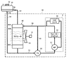
- FIG. 2 is a schematic diagram of an engine cooling device provided in the hydraulic excavator of FIG.
- the engine cooling device 90 (hereinafter referred to as the cooling device 90) includes a radiator 80, a water pump 91, a thermostat 92, a water jacket 93, an EGR cooler 94, and the like.
- thick arrows connecting elements indicate the flow path and flow direction of the cooling water.
- the radiator 80 includes an upper tank 80A, a radiator core 80B, and a lower tank 80C.
- the upper tank 80A is connected to the engine 9 via an upper line 50 (such as a hose), and cooling water from the engine 9 flows into the upper tank 80A.
- the radiator core 80B is connected to the lower side of the upper tank 80A, and has a plurality of cooling water thin tubes and radiating fins (not shown). Cooling air and heat generated by the cooling fan 10 from the cooling water flowing into the upper tank 80A. Replace and cool.
- the lower tank 80C is connected to the lower side of the radiator core 80B and connected to the engine 9 via the lower line 51 (hose or the like), and the cooling water cooled by the radiator core 80B is supplied to the engine 9 via the lower line 51. To do.
- the cooling fan 10 is configured to be driven by the electric motor 12, but may be configured to be driven by the engine 9.
- the water pump 91 is driven by the power of the engine 9, sucks the cooling water supplied to the engine 9, discharges it toward the water jacket 93 and the EGR cooler 94, and circulates the cooling water in the circuit of the cooling device 90.
- the water jacket 93 is a water passage provided around a cylinder (not shown) of the engine 9, and the cooling water sent from the water pump 91 mainly exchanges heat with the engine 9 when passing through the water jacket 91. Cooling.
- the EGR cooler 94 is provided in an EGR pipe (not shown), and cools a part of engine exhaust (hereinafter referred to as EGR gas) passing through the EGR pipe by heat exchange with cooling water.
- EGR gas a part of engine exhaust
- the cooled EGR gas is mixed with intake air and introduced into the cylinder.
- the EGR cooler 94 and the cooling system associated therewith can be omitted.
- the thermostat 92 is a temperature type valve device provided in a bypass line 53 that connects the upper line 50 and the lower line 51.
- the thermostat 92 is provided in the bypass line 53 according to the cooling water temperature so that the temperature of the engine 9 falls within a predetermined range. Adjust the flow rate.
- the thermostat 92 includes, for example, a thermometer and a drive unit. When the coolant temperature measured by the thermometer is equal to or higher than the set temperature, the valve opening is lowered by the drive unit, and when the temperature is lower than the set temperature, the valve opening is raised. . If the valve opening decreases, the amount of cooling water supplied to the engine 9 via the radiator 80 increases, and if the valve opening increases, the amount of cooling water supplied to the engine 9 bypassing the radiator 80 increases.
- Expansion tank The expansion tank 30 (hereinafter referred to as tank 30) is a hermetic reserve tank having a gas-liquid separation function and an air spring function, and loops to the cooling device 90 via an air vent pipe 52 and a makeup pipe 54. Connected.
- the gas-liquid separation function of the tank 30 contributes to taking in the cooling water circulating through the cooling device 90 and removing air from the cooling water.
- the air spring function uses an internal air chamber and contributes to absorbing fluctuations in the internal pressure of the cooling device 90 due to a volume change due to thermal expansion of the cooling water.
- cooling refers to pouring cooling water into the cooling device 90 via the tank 30 for replacement or replenishment of cooling water
- water supply refers to the supply of cooling water from the tank 30 to the cooling device 90.
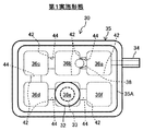
- FIG. 3 is a side view of the tank 30, and FIG. 4 is a plan view.
- the tank 30 includes a tank body 35, a partition wall 42, an inflow port 34, an outflow port 33, a water inlet 31, and a backflow prevention device 38. Next, each element will be explained.
- the tank body 35 is an outer wall of the tank 30 formed of a translucent resin or the like so that the water level can be visually confirmed.
- the shape is not particularly limited, but in this embodiment, the tank body 35 is a rectangular parallelepiped shape with corners having an R shape. is there.
- the tank body 35 employs an upper and lower divided structure including an upper housing 35A and a lower housing 35B.
- the upper housing 35A and the lower housing 35B are integrally formed together with the partition wall 42, and are connected to each other by a flange 35C.
- the boundary between the upper housing 35A and the lower housing 35B is a water level reference line 43 that is a set water level of the tank body 35 when the excavator 1 is in a horizontal posture (for example, when it is in contact with a horizontal plane). It is set as.
- the water level reference line 43 can be arbitrarily set depending on the size of the tank 30, etc., and can be displayed together with a notation that the water level is set if necessary, or two lines indicating the upper limit and the lower limit of the set water level. It is good also as an aspect which displays this line.
- the water level reference line 43 is useful for appropriate management of the water level in the tank 30 by a maintenance worker, and contributes to maintaining an appropriate gas-liquid separation function and air spring function of the tank 30.
- the tank 30 is arranged so that the water level reference line 43 is higher than the uppermost part of the cooling device 90 (strictly, the uppermost part of the cooling water circuit inside the cooling device 90).
- the partition wall 42 is a partition wall extending vertically, and partitions the inside of the tank body 35 into a plurality of (four in this embodiment) separation chambers 36a to 36f adjacent to the front, rear, left and right.
- Each partition 42 includes an upper half part integrally molded with the upper housing 35A and a lower half part integrally molded with the lower housing 35B, and the upper half part is joined by joining the upper housing 35A and the lower housing 35B.
- the lower half is connected.
- the partition wall 42 separating the separation chambers 36 a and 36 b has a cooling water communication hole 44 at a position below the water level reference line 43, and the separation chambers 36 a and 36 b have cooling water below the water level reference line 43.
- the communication holes 44 communicate with each other.
- the separation chambers 36b and 36c, the separation chambers 36c and 36d, the separation chambers 36d and 36e, and the separation chambers 36e and 36f are in communication with each other through the cooling water communication holes 44 below the water level reference line 43, respectively.
- the partition wall 42 that separates the separation chambers 36b and 36e and the partition wall 42 that separates the separation chambers 36a and 36f are not provided with the communication holes 44 for cooling water.
- the separation chambers 36a to 36f communicate with at least one adjacent separation chamber via an air communication hole 45 formed at a position above the water level reference line 43 of the partition wall 42.
- the cooling water inside the tank 30 moves in the order of the separation chamber 36a ⁇ the separation chamber 36b ⁇ the separation chamber 36c ⁇ the separation chamber 36d ⁇ the separation chamber 36f.
- the cooling water inside the tank 30 is gradually moved to the separation chambers 36a to 36f sequentially, and gas-liquid separation is promoted.
- the space (air chamber) above the water level reference line 43 of each separation chamber 36a to 36f performs the above-described air spring function.
- the inflow port 34 is an inlet of cooling water from the cooling device 90 to the tank body 35.
- the upper tank 80A of the radiator 80 and the inflow port 34 are connected via the air vent pipe 52, but the engine 9 or the upper line 50 and the inflow port 34 are connected by the air vent pipe 52. It may be configured to.
- the inflow port 34 is connected to the side surface of the tank body 35 in the present embodiment, and is one of the plurality of separation chambers 36a to 36f at a position below the water level reference line 43, in the present embodiment, the separation chamber. Open to 36a.
- the separation chamber 36a to which the inflow port 34 is connected may be referred to as an “inlet separation chamber 36a”.
- the installation position of the inflow port 34 with respect to the inlet separation chamber 36a can be changed, it is desirable that the inflow port 34 is flooded after water injection regardless of the scene. Therefore, when the excavator 1 is in a horizontal posture and the amount of cooling water whose water level coincides with the water level reference line 43 is stored in the tank body 35, the hydraulic excavator 1 is inclined regardless of which direction the hydraulic excavator 1 tilts. In the range where the inclination angle of the shovel 1 does not exceed a preset maximum allowable inclination angle, it is desirable to install the inflow port 34 at a position where it is not exposed above the coolant level in the tank body 35.
- the maximum allowable inclination angle is, for example, an angle set in advance with respect to the excavator 1 in a range in which oil does not flow out from the oil pan of the engine 9.
- the outflow port 33 is an outlet for cooling water from the tank body 35 to the cooling device 90.
- the lower line 51 and the inflow port 34 are connected via the makeup pipe 54.
- the lower tank 80C of the radiator 80 and the outflow port 33 are connected by the makeup pipe 54.
- the outflow port 33 is one of the plurality of separation chambers 36a to 36f and opens into a separation chamber other than the inlet separation chamber 36a, in this embodiment, the separation chamber 36e at a position below the water level reference line 43. ing.
- the separation chamber 36e to which the outflow port 33 is connected may be referred to as “exit separation chamber 36e”.
- the water injection port 31 is an opening for pouring water into the tank 30, and is a separation level chamber 43a of the separation chambers 36a to 36f other than the inlet separation chamber 36a, in this embodiment, the water level reference line 43 of the outlet separation chamber 36e. It is provided at a position above (for example, the top surface).
- a cap 32 with a pressure valve capable of adjusting the air pressure inside the tank 30 is attached to the water injection port 31 except during water injection, and the pressure in the tank 30 is appropriately maintained.
- the tank 30 is sealed by tightening the cap 32 after water injection.
- the pressure valve may be provided in the upper part of the tank 30 instead of the cap 32.
- the backflow prevention device 38 is a device that prevents the backflow of the cooling water from the inflow port 34 to the outflow port 33 in the inlet separation chamber 36a, and a check valve can be typically used.
- the backflow prevention device 38 is provided in the cooling water communication hole 44 provided in the partition wall 42 that partitions the inlet separation chamber 36a (separates the separation chambers 36a and 36b).
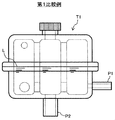
- FIG. 5 is a side view of an expansion tank according to a first comparative example
- FIG. 6 is a side view of an expansion tank according to a second comparative example.
- an expansion tank T1 (hereinafter referred to as tank T1) having a configuration in which the backflow prevention device 38 is omitted from the tank 30 according to the first embodiment is illustrated as a first comparative example.
- an expansion tank T2 (hereinafter referred to as tank T2) having a configuration in which the inflow port P1 of the tank T1 according to the first comparative example is moved to the air chamber (position higher than the water level reference line L) is referred to as the second comparative example.
- tank T2 having a configuration in which the inflow port P1 of the tank T1 according to the first comparative example is moved to the air chamber (position higher than the water level reference line L) is referred to as the second comparative example.
- the first comparative example is a so-called water chamber return type expansion tank that introduces cooling water from a position lower than the water level reference line L
- the second comparative example is a so-called air chamber that introduces cooling water from a position higher than the water level reference line L. It is an example of the expansion tank of a return system.
- an air chamber return type tank T2 as shown in FIG. 6 is generally used in many cases.
- the air chamber return type tank T2 also has the following three problems.
- the first problem is insufficient gas-liquid separation performance. While the engine is operating, the cooling water is pumped from the engine cooling device to the tank T2. In the tank T2, the cooling water is ejected into the air in the tank T2, and the air once enters the cooling water. In addition, it is inevitable that air enters the stored water when the cooling water that has fallen from the air chamber falls to the water surface. Therefore, the gas-liquid separation performance of the air chamber return type tank T2 is lower than that of the water chamber return type tank T1.
- the second problem is the backflow of air to the engine cooling device when the engine is stopped. While the engine is operating, the air vent pipe connected to the inflow port P1 by the water pump is filled with the cooling water, and the cooling water is introduced into the tank T2. However, when the engine stops, the circulation of the cooling water also stops, and the air in the tank T2 flows back to the engine cooling device via the inflow port P1 due to the head difference. At this time, if the vehicle body on which the tank T2 is mounted is inclined and the water level reference line L of the tank T2 is lower than the last part of the engine or radiator, the air flowing backward from the inflow port P1 further flows back to the radiator or engine. Can do. In a cooling water circuit that cools a high-temperature part such as an engine, cooling can be delayed by replacing the cooling water with the backflowed air.
- the third problem is insufficient protection performance of the tank T2.
- the high-temperature water inside the engine cooling device is discharged to the air chamber via the inflow port P1, so that the hot water may directly hit the wall surface of the separation chamber.
- the tank T2 is made of, for example, resin, direct contact with high-temperature water can be a factor that promotes deterioration of the structural material of the tank T2.
- the outlet separation chamber 36e provided with the outflow port 33 is a different separation chamber from the inlet separation chamber 36a provided with the inflow port 34, and cooling the partition wall 42 separating the inlet separation chamber 36a and the adjacent separation chamber 36b.
- a backflow prevention device 38 is provided in the water communication hole 44.
- the water injection port 31 is provided in a separation chamber (in this embodiment, the outlet separation chamber 36e) other than the inlet separation chamber 36a. Therefore, the movement of the cooling water introduced into the inlet separation chamber 36a during the operation of the engine 9 to the separation chamber 36b and the supply of water to the cooling device 90 are allowed, but the inlet separation chambers from the other separation chambers 36b to 36f are allowed at the time of water injection.
- the backflow of the cooling water to 36 a is prevented by the backflow prevention device 38. Since the inflow of the cooling water poured into the tank 30 into the inlet separation chamber 36a is hindered by the backflow prevention device 38, the flooding of the inflow port 34 can be suppressed, and the water injection workability is also good. Therefore, the workability of water injection for the cooling device 90 and the gas-liquid separation performance can be made compatible. Since the cooling efficiency of the cooling device 90 can be improved by improving the gas-liquid separation performance, it is particularly meaningful for a construction machine having a large prime mover and generating a large amount of heat.
- the inflow port 34 is disposed at a position where it is not exposed to the air chamber unless there is an amount of cooling water that satisfies the water level reference line 43 unless the inclination angle of the excavator 1 exceeds the maximum allowable inclination angle. It is preferable. By arranging the inflow port 34 at such a position, even when the engine 9 is stopped, the inflow port 34 is not exposed from the water surface, so that the air in the air chamber can be prevented from flowing back to the cooling device 90. Therefore, it can suppress that the cooling water which retains in high temperature parts, such as the engine 9, is substituted with air, and can suppress the cooling stagnation of a high temperature member. This point is particularly significant for construction machines that operate on slopes.
- the tank body 35 has a vertically divided structure, the partition wall 42, the cooling water communication hole 44, the air communication hole 45, and the like inside the tank body 35 can be easily formed. Also, the backflow prevention device 38 can be easily assembled before joining the upper housing 35A and the lower housing 35B. Therefore, the manufacture of the tank 30 can be facilitated.
- FIG. 7 is a side view of an expansion tank according to a second embodiment of the present invention
- FIG. 8 is a plan view
- FIGS. 7 and 8 correspond to FIGS. 3 and 4 of the first embodiment, respectively. 7 and 8, the same elements as those in the previous drawings are denoted by the same reference numerals, and description thereof is omitted.
- the expansion tank 30A (hereinafter referred to as tank 30A) shown in FIGS. 7 and 8 is different from the tank 30 according to the first embodiment in that an inlet port 34 is provided on the bottom surface of the inlet separation chamber 36a. It is a point (open).
- the inflow port 34 is provided at the center of the bottom surface of the inlet separation chamber 36a (for example, the centers of the inlet separation chamber 36a and the inflow port 34 coincide) is illustrated.
- the inflow port 34 may be installed at a position near the center O of the tank body 35.
- the other configuration of the tank 30A is the same as that of the tank 30 of the first embodiment, including the connection mode and arrangement with the cooling device 90, the construction machine to be applied, the operation, and the like.
- the inflow port is arranged on the bottom surface of the expansion tank together with the outflow port, so that it becomes impossible to inject water when the inflow port is flooded. Therefore, even in the water chamber return method, the inflow port is often arranged as high as possible with respect to the outflow port in order to ensure the water injection performance.
- the backflow prevention device 38 is provided, so that the flooding of the inflow port 34 due to the poured cooling water can be suppressed. Can be provided.
- the inflow port 34 When the inflow port 34 is provided on the bottom surface of the tank body 35 as in the present embodiment, the maximum inclination angle is not exceeded compared to the configuration in which the inflow port 34 is provided on the side surface of the tank body 35 as in the first embodiment. It is easy to adopt a configuration in which the opening of the inflow port 34 is maintained under the surface of the cooling water under conditions. In particular, the position of the center of the inlet separation chamber 36a or the position closer to the center O of the tank body 35 than that is easily satisfied. Therefore, it is more advantageous in obtaining the effect of suppressing the cooling stagnation of the high temperature member.
- the configuration in which the cooling water in the inlet separation chamber 36a moves only to the separation chamber 36b has been exemplified.
- a cooling water communication hole 44 is added to the partition wall 42 separating the separation chambers 36a and 36f, and the inlet The cooling water may be moved from the separation chamber 36a to a plurality of separation chambers.
- the backflow prevention device 38 since it is necessary to install the backflow prevention device 38 in all of the plurality of cooling water communication holes 44 that connect the inlet separation chamber 36a and the adjacent separation chamber, the backflow prevention device 38 depends on the connection structure of the separation chamber. Multiple can be installed.
- the number of separation chambers communicating with the inlet separation chamber 36a and the cooling water communication hole 44 is limited to a single number as in the first and second embodiments, the number of the backflow prevention devices 38 is sufficient, and the structure is simplified. There is a merit of low cost.
- the backflow prevention device 38 may be provided in the inflow port 34 instead. good. Needless to say, in this case, the backflow prevention device 38 allows the flow of the cooling water flowing into the inlet separation chamber 36a from the cooling device 90, and the flow of the cooling water from the inflow port 34 to the cooling device 90 is blocked. It is a configuration.
- the number of separation chambers in the tanks 30 and 30A is not limited and may be plural. Therefore, the required number of partition walls 42 is at least one.
- cooling water communication holes 44 facing in the same direction on the same axis as shown in FIGS. 3, 4, 7, and 8. In some cases, the center axis is shifted. The same applies to the air communication hole 45. Further, it is not always necessary to make the sizes of the cooling water communication holes 44 uniform, and they may be uneven. The same applies to the air communication hole 45.
- the backflow prevention device 38 is not necessarily limited to the check valve, and a float valve or the like can be applied.
- the valve is closed when the water level is lower than the set water level set lower than the water level reference line 43 to suppress the flooding of the inflow port 34 and the valve is opened when the water level is higher than the set water level. It can be configured to allow water supply to the cooling device 90.
- SYMBOLS 1 Hydraulic excavator (construction machine), 9 ... Engine (motor), 30, 30A ... Expansion tank, 31 ... Water injection port, 33 ... Outflow port, 34 ... Inflow port, 35 ... Tank main body, 36a-36f ... Separation chamber, 36a ... inlet separation chamber, 36e ... outlet separation chamber, 38 ... backflow prevention device, 42 ... partition wall, 43 ... water level reference line, 44 ... cooling water communication hole (communication hole), 90 ... engine cooling device (cooling device), O ... Center of tank body
Landscapes
- Engineering & Computer Science (AREA)
- Chemical & Material Sciences (AREA)
- Combustion & Propulsion (AREA)
- Mechanical Engineering (AREA)
- General Engineering & Computer Science (AREA)
- Transportation (AREA)
- Mining & Mineral Resources (AREA)
- Civil Engineering (AREA)
- Structural Engineering (AREA)
- Component Parts Of Construction Machinery (AREA)
- Cooling, Air Intake And Gas Exhaust, And Fuel Tank Arrangements In Propulsion Units (AREA)
Abstract
Selon l'invention, un vase d'expansion (30) est un vase de type fermé qui est raccordé à un dispositif de refroidissement de moteur et qui sépare l'air de l'eau de refroidissement circulant dans le dispositif de refroidissement, et est caractérisé par le fait qu'il comprend : un corps de réservoir (35) ; une pluralité de cloisons (42) comportant des trous de communication (44) à des emplacements plus bas qu'une ligne de référence de niveau d'eau (43) et divisant l'intérieur du corps de réservoir (35) en une pluralité de chambres de séparation (36a-36f) ; un orifice d'entrée (34) qui est raccordé, au niveau d'un emplacement plus bas que la ligne de référence de niveau d'eau (43), à la chambre de séparation (36a) ; un orifice de sortie (33) qui est raccordé, au niveau d'un emplacement plus bas que la ligne de référence de niveau d'eau (43), à la chambre de séparation (36e) différente de la chambre de séparation (36a) ; une entrée d'eau (31) située dans l'une des chambres de séparation différente de la chambre de séparation (36a) ; et un dispositif de non-retour (38) disposé dans le trou de communication (44) de la cloison (42) qui définit la chambre de séparation (36a).
Applications Claiming Priority (2)
| Application Number | Priority Date | Filing Date | Title |
|---|---|---|---|
| JP2016-111336 | 2016-06-02 | ||
| JP2016111336A JP2019132130A (ja) | 2016-06-02 | 2016-06-02 | エクスパンションタンク |
Publications (1)
| Publication Number | Publication Date |
|---|---|
| WO2017209145A1 true WO2017209145A1 (fr) | 2017-12-07 |
Family
ID=60478604
Family Applications (1)
| Application Number | Title | Priority Date | Filing Date |
|---|---|---|---|
| PCT/JP2017/020150 Ceased WO2017209145A1 (fr) | 2016-06-02 | 2017-05-30 | Vase d'expansion |
Country Status (2)
| Country | Link |
|---|---|
| JP (1) | JP2019132130A (fr) |
| WO (1) | WO2017209145A1 (fr) |
Families Citing this family (1)
| Publication number | Priority date | Publication date | Assignee | Title |
|---|---|---|---|---|
| CN114837796B (zh) * | 2022-05-13 | 2023-06-06 | 浙江吉利控股集团有限公司 | 一种集成式膨胀水壶、冷却系统及汽车 |
Citations (5)
| Publication number | Priority date | Publication date | Assignee | Title |
|---|---|---|---|---|
| JPS63140145U (fr) * | 1987-03-06 | 1988-09-14 | ||
| JP2007009752A (ja) * | 2005-06-29 | 2007-01-18 | Toyota Motor Corp | リザーブタンク |
| JP2007146660A (ja) * | 2005-11-24 | 2007-06-14 | Denso Corp | リザーブタンク |
| JP2009041450A (ja) * | 2007-08-09 | 2009-02-26 | Hitachi Ltd | 内燃機関の冷却用電動ポンプ及びこれを用いた冷却装置 |
| EP3012429A1 (fr) * | 2014-10-21 | 2016-04-27 | Scania CV AB | Réservoir d'expansion et système de refroidissement comportant un tel réservoir |
-
2016
- 2016-06-02 JP JP2016111336A patent/JP2019132130A/ja active Pending
-
2017
- 2017-05-30 WO PCT/JP2017/020150 patent/WO2017209145A1/fr not_active Ceased
Patent Citations (5)
| Publication number | Priority date | Publication date | Assignee | Title |
|---|---|---|---|---|
| JPS63140145U (fr) * | 1987-03-06 | 1988-09-14 | ||
| JP2007009752A (ja) * | 2005-06-29 | 2007-01-18 | Toyota Motor Corp | リザーブタンク |
| JP2007146660A (ja) * | 2005-11-24 | 2007-06-14 | Denso Corp | リザーブタンク |
| JP2009041450A (ja) * | 2007-08-09 | 2009-02-26 | Hitachi Ltd | 内燃機関の冷却用電動ポンプ及びこれを用いた冷却装置 |
| EP3012429A1 (fr) * | 2014-10-21 | 2016-04-27 | Scania CV AB | Réservoir d'expansion et système de refroidissement comportant un tel réservoir |
Also Published As
| Publication number | Publication date |
|---|---|
| JP2019132130A (ja) | 2019-08-08 |
Similar Documents
| Publication | Publication Date | Title |
|---|---|---|
| US10233822B2 (en) | Expansion tank | |
| JP5054851B2 (ja) | 電動式建設機械 | |
| KR101894980B1 (ko) | 건설 기계 | |
| JP7065925B1 (ja) | 建設機械の冷却装置 | |
| JP2024036372A (ja) | 作業機械 | |
| WO2017209145A1 (fr) | Vase d'expansion | |
| US12305564B2 (en) | Arrangement structure of cooling system in construction equipment | |
| CN111164282A (zh) | 作业机械 | |
| CN111886386B (zh) | 建筑机械 | |
| JPH11190046A (ja) | 油圧ショベル | |
| JP6962872B2 (ja) | 建設機械 | |
| JP5917383B2 (ja) | 建設機械 | |
| JP7429176B2 (ja) | 建設機械 | |
| KR102406369B1 (ko) | 건설기계 | |
| CN212427315U (zh) | 工程机械 | |
| JP2000203274A (ja) | 建設機械の冷却装置 | |
| JP3299138B2 (ja) | 建設機械 | |
| JP2007051454A (ja) | 建設機械の作動油冷却システム | |
| JP2022141310A (ja) | 建設機械 | |
| JP2022186184A (ja) | 作業機械 | |
| JP4208180B2 (ja) | 油圧ショベルにおけるキャブへのエンジン熱伝達遮断構造 | |
| JP2001227340A (ja) | 建設機械のラジエータ装置 | |
| JP2008082020A (ja) | バックホー | |
| JPH11324674A (ja) | 建設機械のラジエータ装置 | |
| JP2007085090A (ja) | 建設機械の作動油冷却システム |
Legal Events
| Date | Code | Title | Description |
|---|---|---|---|
| 121 | Ep: the epo has been informed by wipo that ep was designated in this application |
Ref document number: 17806698 Country of ref document: EP Kind code of ref document: A1 |
|
| NENP | Non-entry into the national phase |
Ref country code: DE |
|
| 122 | Ep: pct application non-entry in european phase |
Ref document number: 17806698 Country of ref document: EP Kind code of ref document: A1 |
|
| NENP | Non-entry into the national phase |
Ref country code: JP |