WO2017209202A1 - Dispositif d'extinction d'incendie en aérosol et tableau de commande électrique utilisant ledit dispositif - Google Patents
Dispositif d'extinction d'incendie en aérosol et tableau de commande électrique utilisant ledit dispositif Download PDFInfo
- Publication number
- WO2017209202A1 WO2017209202A1 PCT/JP2017/020328 JP2017020328W WO2017209202A1 WO 2017209202 A1 WO2017209202 A1 WO 2017209202A1 JP 2017020328 W JP2017020328 W JP 2017020328W WO 2017209202 A1 WO2017209202 A1 WO 2017209202A1
- Authority
- WO
- WIPO (PCT)
- Prior art keywords
- aerosol
- fire
- extinguishing device
- fire extinguishing
- electric control
- Prior art date
- Legal status (The legal status is an assumption and is not a legal conclusion. Google has not performed a legal analysis and makes no representation as to the accuracy of the status listed.)
- Ceased
Links
Images


Classifications
-
- A—HUMAN NECESSITIES
- A62—LIFE-SAVING; FIRE-FIGHTING
- A62C—FIRE-FIGHTING
- A62C3/00—Fire prevention, containment or extinguishing specially adapted for particular objects or places
- A62C3/16—Fire prevention, containment or extinguishing specially adapted for particular objects or places in electrical installations, e.g. cableways
-
- A—HUMAN NECESSITIES
- A62—LIFE-SAVING; FIRE-FIGHTING
- A62C—FIRE-FIGHTING
- A62C35/00—Permanently-installed equipment
- A62C35/02—Permanently-installed equipment with containers for delivering the extinguishing substance
- A62C35/10—Containers destroyed or opened by flames or heat
-
- A—HUMAN NECESSITIES
- A62—LIFE-SAVING; FIRE-FIGHTING
- A62C—FIRE-FIGHTING
- A62C5/00—Making of fire-extinguishing materials immediately before use
-
- A—HUMAN NECESSITIES
- A62—LIFE-SAVING; FIRE-FIGHTING
- A62D—CHEMICAL MEANS FOR EXTINGUISHING FIRES OR FOR COMBATING OR PROTECTING AGAINST HARMFUL CHEMICAL AGENTS; CHEMICAL MATERIALS FOR USE IN BREATHING APPARATUS
- A62D1/00—Fire-extinguishing compositions; Use of chemical substances in extinguishing fires
- A62D1/06—Fire-extinguishing compositions; Use of chemical substances in extinguishing fires containing gas-producing, chemically-reactive components
-
- F—MECHANICAL ENGINEERING; LIGHTING; HEATING; WEAPONS; BLASTING
- F03—MACHINES OR ENGINES FOR LIQUIDS; WIND, SPRING, OR WEIGHT MOTORS; PRODUCING MECHANICAL POWER OR A REACTIVE PROPULSIVE THRUST, NOT OTHERWISE PROVIDED FOR
- F03D—WIND MOTORS
- F03D9/00—Adaptations of wind motors for special use; Combinations of wind motors with apparatus driven thereby; Wind motors specially adapted for installation in particular locations
- F03D9/10—Combinations of wind motors with apparatus storing energy
- F03D9/11—Combinations of wind motors with apparatus storing energy storing electrical energy
-
- Y—GENERAL TAGGING OF NEW TECHNOLOGICAL DEVELOPMENTS; GENERAL TAGGING OF CROSS-SECTIONAL TECHNOLOGIES SPANNING OVER SEVERAL SECTIONS OF THE IPC; TECHNICAL SUBJECTS COVERED BY FORMER USPC CROSS-REFERENCE ART COLLECTIONS [XRACs] AND DIGESTS
- Y02—TECHNOLOGIES OR APPLICATIONS FOR MITIGATION OR ADAPTATION AGAINST CLIMATE CHANGE
- Y02E—REDUCTION OF GREENHOUSE GAS [GHG] EMISSIONS, RELATED TO ENERGY GENERATION, TRANSMISSION OR DISTRIBUTION
- Y02E10/00—Energy generation through renewable energy sources
- Y02E10/70—Wind energy
- Y02E10/72—Wind turbines with rotation axis in wind direction
-
- Y—GENERAL TAGGING OF NEW TECHNOLOGICAL DEVELOPMENTS; GENERAL TAGGING OF CROSS-SECTIONAL TECHNOLOGIES SPANNING OVER SEVERAL SECTIONS OF THE IPC; TECHNICAL SUBJECTS COVERED BY FORMER USPC CROSS-REFERENCE ART COLLECTIONS [XRACs] AND DIGESTS
- Y02—TECHNOLOGIES OR APPLICATIONS FOR MITIGATION OR ADAPTATION AGAINST CLIMATE CHANGE
- Y02E—REDUCTION OF GREENHOUSE GAS [GHG] EMISSIONS, RELATED TO ENERGY GENERATION, TRANSMISSION OR DISTRIBUTION
- Y02E70/00—Other energy conversion or management systems reducing GHG emissions
- Y02E70/30—Systems combining energy storage with energy generation of non-fossil origin
Definitions
- the present invention relates to an aerosol fire extinguishing device capable of extinguishing or suppressing a fire by generating aerosol by combustion and an electric control panel using the same.
- an aerosol fire extinguishing apparatus that extinguishes or suppresses a flame by burning an extinguishing agent to generate an aerosol (for example, Patent Document 1).
- Such an aerosol fire extinguishing apparatus includes a large number of assembly parts such as an outer cylinder, an inner cylinder, a fire extinguishing chemical pellet, an electric igniter, two coolant layers, and three spacers.
- the above-described aerosol fire extinguishing apparatus requires a certain storage space, and is suitable for installation in an electric control panel having a limited space such as a capacitor panel case stored in a nacelle of a wind power generator. Absent.
- the above-described aerosol fire extinguishing device does not operate when power supply is cut off.
- an object of the present invention is to provide an aerosol fire extinguishing device that can be installed in a limited space in the storage space of an electric control panel and does not require a power source for operation.
- the present invention is installed in an electric control panel having a space for storing an electric control device, and has a container having an opening for ejecting aerosol into the space, and is stored in the container.
- a fire extinguishing agent that generates the aerosol by combustion, and a fire extinguishing agent that is provided on a surface facing the opening in the fire extinguishing agent and that ignites when a predetermined temperature is exceeded and ignites the fire extinguishing agent. Provide an aerosol fire extinguishing device.
- the aerosol fire extinguishing device of the present invention having the above-described configuration further includes a screen that covers the opening side surface of the ignition agent so as to protect the ignition agent.
- the aerosol fire-extinguishing device of the present invention having the above-described configuration further includes a flange that is fixed to the installation surface and detachably mounts the container.
- the container has a protruding piece that protrudes outward, and the flange has an engaging piece that engages with the protruding piece. preferable.
- the extinguishing agent contains potassium chlorate
- the DSC evaluation 100 to 400 ° C., 10 ° C. per minute heating
- endothermic peak total amount is 100 J / g to 900 J / G.
- the present invention also provides an electric control panel characterized by incorporating an electric control device and the aerosol fire extinguishing device according to any one of the above.
- the electric control device is a phase control capacitor installed in a wind power generator nacelle.
- an aerosol fire extinguishing device that can be installed in a limited space in the storage space of the electric control panel and does not require a power source for operation.
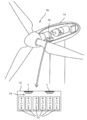
- the aerosol fire extinguishing device 1 is installed in a capacitor panel case 72 housed in a nacelle 71 of a wind power generator 70.
- the capacitor panel case 72 is a rectangular parallelepiped container that accommodates a plurality of capacitors 73 in a state of being aligned vertically and horizontally.
- the closed storage space in the capacitor panel case 72 there is a slight empty space 74 between the plurality of capacitors 73 and the top plate of the capacitor panel case 72.
- the closed storage space in the capacitor panel case 72 does not need to be sealed and may have a gap.
- the plurality of capacitors 73 are installed for phase control (slow phase) of power generated by the wind power generator 70.
- the aerosol fire extinguishing device 1 is provided in such an empty space 74, as will be described later, it is much more compact than the conventional one.
- the aerosol fire-extinguishing device 1 is installed in the empty space 74 by, for example, being fixed to the inner surface of the top plate of the capacitor panel case 72 so that the radiating aerosol covers all of the plurality of capacitors 73.
- a plurality of aerosol fire extinguishing devices 1 may be provided depending on the fire extinguishing target.
- the installation place of the aerosol fire extinguishing device 1 is not limited to the wind power generator described above.
- Examples of other installation locations are locations with ignition sources such as nuclear power plants, geothermal power plants, computer server rooms, household storage batteries, large switchboards, control panels, ferris wheels and other playground equipment.
- the ignition source is not limited to the capacitor panel.
- the aerosol fire extinguishing device 1 may be applied to devices and elements (hereinafter, referred to as electric control devices) that control electricity, such as transformers, circuit breakers, switches, and phase control (phase-advance) inductors.
- Insulating oil used in this type of electrical control equipment may evaporate and ignite due to overheating caused by lightning strikes, etc., or the electrical control equipment itself may ignite due to overheating due to poor contact, etc. In order to suppress the flame, the aerosol fire extinguishing device 1 is used.
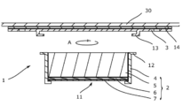
- the aerosol fire extinguishing device 1 has a so-called flat shape and includes a main body 2 and a flange 3.
- the flange 3 is attached to the installation surface 30 such as the top plate of the capacitor panel case 72 described above, and the main body 2 can be detachably mounted.
- these components will be described in order.
- the main body 2 includes a container 4, a fire extinguishing agent 5, an ignition agent 6, and a screen 7 as shown in FIG.
- the container 4 has a short cylindrical shape (that is, the diameter is larger than the height (length)) and stores the fire extinguishing agent 5, the ignition agent 6, and the screen 7.
- the container 4 is formed of a metal such as iron or stainless steel, for example, but may be formed of other materials as long as the required strength and heat resistance are provided.
- the container 4 has an opening 11 for ejecting aerosol at one end and a protruding piece 12 protruding outward at the other end.
- the diameter of the opening 11 is smaller than the inner diameter of the container 4 so that the extinguishing agent 5, the igniting agent 6, and the screen 7 accommodated in the container 4 do not fall out of the opening 11.
- a plurality of protruding pieces 12 are provided on the outer peripheral surface of the container 4 so as to engage with the engaging pieces 13 of the flange 3.
- the fire extinguishing agent 5 is a chemical that is stored in the container 4 and generates aerosol by combustion.
- the fire extinguisher 5 has a disk shape or a column shape.
- the fire extinguishing agent 5 may be a non-explosive composition containing potassium chlorate and an aerosol generating component, or may be an explosive composition. The composition of the fire extinguishing agent 5 will be described later.
- the igniting agent 6 is provided so as to cover the surface of the extinguishing agent 5 on the opening 11 side, and ignites and ignites the extinguishing agent 5 when a predetermined temperature is exceeded.
- a chemical reaction may be started at around 200 ° C. to ignite.
- the igniting agent 6 is formed thinner than the extinguishing agent 5 and has a sheet shape or plate shape.
- the igniting agent 6 may cover the surface of the extinguishing agent 5 on the opening 11 side entirely or partially.
- the composition of the ignition agent 6 is, for example, nitrocellulose or a composition containing the same.
- the screen 7 is a member that covers the surface of the igniting agent 6 on the side of the opening 11 so as to protect the igniting agent 6 from, for example, contact with the capacitor 74 and can emit aerosol (white smoke) by the ignition of the igniting agent 6. is there.
- the screen 7 is a wire mesh, for example, and can pass the aerosol generated in the fire extinguishing agent 5 to the opening 11 side while covering the ignition agent 6.
- the screen 7 also prevents the extinguishing agent 5 and the ignition agent 6 from dropping from the opening 11.
- the thickness of the screen 7 is approximately the same as the thickness of the ignition agent 6, for example.
- the main body 2 having such a configuration is detachably attached to the flange 3 via the protruding piece 12 of the container 4.
- the flange 3 is a disk-shaped member that is attached to the installation surface 30, and the main body 2 is detachably mounted.
- the flange 3 is fixed to the installation surface 30 by the double-sided tape 14, but may be fixed to the installation surface 30 by other fixing means such as an adhesive or a screw.
- the flange 3 is formed of a metal such as iron or stainless steel, for example, but may be formed of other materials as long as the required strength and heat resistance are provided.
- the flange 3 has an engagement piece 13 for engaging with the protruding piece 12 of the container 4. Therefore, in the state where the main body 2 is mounted on the flange 3 as shown in FIG. 1, the movement of the protruding piece 12 in the direction away from the installation surface 30 is restricted by the engaging piece 13. As a result, the mounting state of the main body 2 on the flange 3 is maintained. In order to remove the main body 2 from the flange 3, for example, as shown by an arrow A in FIG. 2, the main body 2 is rotated with respect to the flange 3 to release the engagement between the protruding piece 12 and the engaging piece 13. The main body 2 may be moved away from the flange 3.
- the dimensions of the aerosol fire extinguishing device 1 having such a configuration are, for example, an outer diameter of the main body 2 of 70 mm, a thickness including the main body 2 and the flange 3 (that is, a width from the installation surface 30) of 35 mm.
- the weight of the fire extinguishing agent 5 is about 100 g.
- the dimensions of the main body 2 including the extinguishing agent 5 may be appropriately changed according to the required operation amount and operating time of the extinguishing agent 5.
- the aerosol fire extinguishing device 1 is small and can be installed in a small space. Further, for example, as shown in FIG. 4, a plurality of aerosol fire extinguishing devices 1 may be installed according to required fire extinguishing performance and fire extinguishing range.
- ⁇ Fire extinguisher composition The fire extinguisher composition used in the present embodiment will be described. As a fire extinguisher composition, various materials can be used as well as those belonging to the classification of explosives.
- the fire extinguishing agent in the present embodiment contains, for example, 20 to 50% by mass of fuel (component A) and 80 to 50% by mass of chlorate (component B), and further the total amount of the fuel and chlorate is 100% by mass. 6 to 1000 parts by mass of potassium salt (component C) with respect to parts, and the thermal decomposition starting temperature is in the range of more than 90 ° C. to 260 ° C.
- the fuel as the A component is a component for generating aerosol (potassium radical) derived from the potassium salt of the C component by generating thermal energy by combustion together with the chlorate as the B component.
- Such component A fuels include dicyandiamide, nitroguanidine, guanidine nitrate, urea, melamine, melamine cyanurate, Avicel, guar gum, sodium carboxymethylcellulose, carboxymethylcellulose potassium, carboxymethylcellulose ammonium, nitrocellulose, aluminum, boron, magnesium. , Magnalium, zirconium, titanium, titanium hydride, tungsten and silicon are preferred. Among these, sodium carboxymethyl cellulose is particularly preferable from the viewpoint that the effect of the present invention of generating an aerosol and extinguishing the fire can be obtained more reliably.
- B component chlorate is a powerful oxidant, and is a component for generating thermal energy by combustion with the A component fuel and generating aerosol (potassium radical) derived from the potassium salt of C component.
- the B component chlorate is preferably selected from at least one of potassium chlorate, sodium chlorate, strontium chlorate, ammonium chlorate and magnesium chlorate.
- potassium chlorate is particularly preferable from the viewpoint that the effects of the present invention can be obtained more reliably.
- the content ratio in 100 mass% of the fuel of component A and the chlorate of component B is as follows.
- Component A 20-50% by mass
- the potassium salt of component C is a component for generating aerosol (potassium radical) by the heat energy generated by the combustion of component A and component B.
- potassium salt of component C examples include potassium acetate, potassium propionate, monopotassium citrate, dipotassium citrate, tripotassium citrate, ethylenediaminetetraacetic acid monohydrogentripotassium, ethylenediaminetetraacetic acid dipotassium dihydrogen, ethylenediaminetetraacetate. Preference is given to at least one selected from tripotassium acetate hydrogen acetate, tetrapotassium ethylenediaminetetraacetate, potassium hydrogen phthalate, dipotassium phthalate, potassium hydrogen oxalate, dipotassium oxalate and potassium bicarbonate. Among these, potassium acetate or tripotassium citrate is particularly preferable from the viewpoint that the effects of the present invention can be obtained more reliably.
- the content ratio of component C is preferably 6 to 1000 parts by mass, more preferably 10 to 900 parts by mass, and particularly preferably 10 to 100 parts by mass with respect to 100 parts by mass of the total amount of component A and component B. It is.
- the fire extinguisher composition of the present embodiment has a thermal decomposition starting temperature in the range of over 90 ° C. to 260 ° C., preferably over 150 ° C. to 260 ° C.
- a range of the thermal decomposition start temperature can be prepared by combining the A component, the B component, and the C component in the above ratio.
- the fire extinguisher composition of the present embodiment satisfies the above thermal decomposition start temperature range, so that the A component and the B component are automatically received by receiving heat at the time of fire without using an ignition device, for example. It can be ignited and burned to generate an aerosol (potassium radical) derived from the C component and extinguish the fire.
- the fire extinguisher composition of the present embodiment contains potassium chlorate, and DSC evaluation (100 to 400 ° C., 10 ° C. per minute heating) endothermic peak total amount is 100 J / g to 900 J / g, more reliably. It is preferable from the viewpoint of exhibiting fire extinguishing performance.
- the total endothermic peak can be controlled by adjusting the combination and blending ratio of the above A component, B component and C component.
- sodium carboxylcarboxylate is used for the A component
- potassium chlorate is used for the B component
- acetic acid is used for the C component.
- the total endothermic peak amount can be more reliably controlled within the above range.
- FIG. 3 operation
- movement of the aerosol fire extinguishing device 1 is demonstrated.
- the storage container in which the aerosol fire-extinguishing device 1 is installed and the stored items (the capacitor panel case 72 and the plurality of capacitors 73 in the example of FIG. 4) are omitted.
- the aerosol fire extinguishing device 1 shall be installed so that the opening part 11 may be faced with respect to the stored item used as a fire source.
- the aerosol fire extinguishing device 1 is not activated when there is no fire in the storage container. In other words, it can be said that the aerosol fire extinguishing device 1 monitors whether or not it is generated.
- the ignition agent 6 when a fire 50 is generated from the stored item and the temperature of the ignition agent 6 reaches a predetermined temperature (for example, 200 ° C.), the ignition agent 6 is ignited to generate a fire type 51. Ignite 5 It can be said that the ignition agent 6 has both the role of a temperature sensor and the role of an igniter.
- the fire extinguisher 5 When the fire extinguisher 5 is ignited, as shown in FIG. 3C, the fire extinguisher 5 generates an aerosol 52 by combustion. The generated aerosol 52 is ejected from the opening 11 toward the flame 50. Then, the flame 50 is extinguished or suppressed by the fire extinguishing action of the aerosol 52 described above.
- the aerosol fire extinguishing device 1 is small, it can be installed in a small space in the storage space of the electric control panel. Moreover, since the aerosol fire extinguishing device 1 does not require an external power source for detecting a fire and igniting a fire extinguisher, it can operate even during a power failure. Therefore, for example, a fire extinguishing operation can be quickly performed for a fire caused by a lightning strike.
- the main body 2 since the main body 2 is detachably attached to the flange 3, the main body 2 can be easily replaced. Moreover, daily maintenance is unnecessary. Therefore, maintenance / inspection work can be reduced.
- the operating amount and operating time of the extinguishing agent 5 can be easily adjusted. Therefore, the fire-extinguishing agent 5 can be radiated according to needs.
- Fire extinguisher 5 is a potassium compound and is safe for the human body. Moreover, after the emission of the fire extinguishing agent 5, for example, cleaning is not required like fire extinguishing with ABC powder. Furthermore, secondary damage such as a short circuit of an installed device (capacitor in the example of FIG. 4) such as fire extinguishing due to high expansion bubbles can be prevented. Therefore, the equipment can be restored in a short time after the fire is extinguished.
Landscapes
- Engineering & Computer Science (AREA)
- Business, Economics & Management (AREA)
- Emergency Management (AREA)
- Public Health (AREA)
- Health & Medical Sciences (AREA)
- Chemical & Material Sciences (AREA)
- Power Engineering (AREA)
- General Chemical & Material Sciences (AREA)
- Chemical Kinetics & Catalysis (AREA)
- Life Sciences & Earth Sciences (AREA)
- Sustainable Development (AREA)
- Sustainable Energy (AREA)
- Combustion & Propulsion (AREA)
- Mechanical Engineering (AREA)
- General Engineering & Computer Science (AREA)
- Fire-Extinguishing By Fire Departments, And Fire-Extinguishing Equipment And Control Thereof (AREA)
- Wind Motors (AREA)
Abstract
La présente invention vise à fournir un dispositif d'extinction d'incendie en aérosol qui peut être installé dans un espace libre limité dans un espace de stockage d'un tableau de commande électrique et qui ne nécessite pas d'alimentation électrique pour fonctionner. Pour parvenir à ce résultat, le présent dispositif d'extinction d'incendie en aérosol est caractérisé en ce qu'il comprend : un contenant installé dans un tableau de commande électrique ayant un espace pour stocker un équipement de commande électrique, le contenant ayant une ouverture permettant de faire sortir un aérosol dans l'espace ; un agent extincteur stocké dans le contenant, l'agent extincteur générant l'aérosol par combustion ; et un agent d'allumage disposé sur la surface de l'agent extincteur faisant face à l'ouverture, l'agent d'allumage détectant un incendie et allumant l'agent extincteur lorsqu'une température prédéterminée est dépassée.
Priority Applications (1)
| Application Number | Priority Date | Filing Date | Title |
|---|---|---|---|
| JP2018520971A JP6568316B2 (ja) | 2016-06-01 | 2017-05-31 | エアロゾル消火デバイス及びこれを用いた電気制御盤 |
Applications Claiming Priority (2)
| Application Number | Priority Date | Filing Date | Title |
|---|---|---|---|
| JP2016110132 | 2016-06-01 | ||
| JP2016-110132 | 2016-06-01 |
Publications (1)
| Publication Number | Publication Date |
|---|---|
| WO2017209202A1 true WO2017209202A1 (fr) | 2017-12-07 |
Family
ID=60477499
Family Applications (1)
| Application Number | Title | Priority Date | Filing Date |
|---|---|---|---|
| PCT/JP2017/020328 Ceased WO2017209202A1 (fr) | 2016-06-01 | 2017-05-31 | Dispositif d'extinction d'incendie en aérosol et tableau de commande électrique utilisant ledit dispositif |
Country Status (2)
| Country | Link |
|---|---|
| JP (1) | JP6568316B2 (fr) |
| WO (1) | WO2017209202A1 (fr) |
Cited By (7)
| Publication number | Priority date | Publication date | Assignee | Title |
|---|---|---|---|---|
| CN109059694A (zh) * | 2018-07-17 | 2018-12-21 | 常州大学 | 管道内冲击波破膜抑制粉尘二次爆炸的装置 |
| WO2020050209A1 (fr) * | 2018-09-04 | 2020-03-12 | ヤマトプロテック株式会社 | Extincteur |
| CN111578491A (zh) * | 2020-05-25 | 2020-08-25 | 珠海格力电器股份有限公司 | 电器盒组件及具有其的空调器 |
| KR102357714B1 (ko) * | 2021-04-26 | 2022-02-08 | 고려화공 주식회사 | 초소형 공간의 화재진압용 스티커형 자동소화장치 |
| KR102675399B1 (ko) * | 2023-10-25 | 2024-06-17 | 강운공업주식회사 | 고체에어로졸을 이용한 2차전지 소화시스템 |
| RU233054U1 (ru) * | 2023-06-19 | 2025-04-02 | Евгений Сергеевич Каплун | Противопожарная электромонтажная коробка |
| US12364888B2 (en) | 2020-01-22 | 2025-07-22 | Yamato Protec Corporation | Fire extinguishing sheet |
Families Citing this family (1)
| Publication number | Priority date | Publication date | Assignee | Title |
|---|---|---|---|---|
| US20260069906A1 (en) * | 2023-06-19 | 2026-03-12 | Yuriy Aleksandrovich GABLIYA | Fireproof electrical junction box (embodiments) |
Citations (3)
| Publication number | Priority date | Publication date | Assignee | Title |
|---|---|---|---|---|
| JPS4940297U (fr) * | 1972-07-06 | 1974-04-09 | ||
| JP2011078564A (ja) * | 2009-10-07 | 2011-04-21 | Hochiki Corp | エアロゾル消火装置 |
| JP2015123277A (ja) * | 2013-12-27 | 2015-07-06 | 日本工機株式会社 | 移動体搭載用エアロゾル消火装置及びこれに用いるエアロゾル消火薬剤 |
-
2017
- 2017-05-31 WO PCT/JP2017/020328 patent/WO2017209202A1/fr not_active Ceased
- 2017-05-31 JP JP2018520971A patent/JP6568316B2/ja active Active
Patent Citations (3)
| Publication number | Priority date | Publication date | Assignee | Title |
|---|---|---|---|---|
| JPS4940297U (fr) * | 1972-07-06 | 1974-04-09 | ||
| JP2011078564A (ja) * | 2009-10-07 | 2011-04-21 | Hochiki Corp | エアロゾル消火装置 |
| JP2015123277A (ja) * | 2013-12-27 | 2015-07-06 | 日本工機株式会社 | 移動体搭載用エアロゾル消火装置及びこれに用いるエアロゾル消火薬剤 |
Cited By (14)
| Publication number | Priority date | Publication date | Assignee | Title |
|---|---|---|---|---|
| CN109059694B (zh) * | 2018-07-17 | 2020-06-30 | 常州大学 | 管道内冲击波破膜抑制粉尘二次爆炸的装置 |
| CN109059694A (zh) * | 2018-07-17 | 2018-12-21 | 常州大学 | 管道内冲击波破膜抑制粉尘二次爆炸的装置 |
| KR102773005B1 (ko) * | 2018-09-04 | 2025-02-27 | 야마토 프로텍 가부시키가이샤 | 소화기 |
| WO2020050209A1 (fr) * | 2018-09-04 | 2020-03-12 | ヤマトプロテック株式会社 | Extincteur |
| KR20210046741A (ko) * | 2018-09-04 | 2021-04-28 | 야마토 프로텍 가부시키가이샤 | 소화기 |
| JPWO2020050209A1 (ja) * | 2018-09-04 | 2021-08-30 | ヤマトプロテック株式会社 | 消火具 |
| US20210331013A1 (en) * | 2018-09-04 | 2021-10-28 | Yamato Protec Corporation | Fire extinguisher |
| JP7220927B2 (ja) | 2018-09-04 | 2023-02-13 | ヤマトプロテック株式会社 | 消火具 |
| US12318645B2 (en) * | 2018-09-04 | 2025-06-03 | Yamato Protec Corporation | Fire extinguisher |
| US12364888B2 (en) | 2020-01-22 | 2025-07-22 | Yamato Protec Corporation | Fire extinguishing sheet |
| CN111578491A (zh) * | 2020-05-25 | 2020-08-25 | 珠海格力电器股份有限公司 | 电器盒组件及具有其的空调器 |
| KR102357714B1 (ko) * | 2021-04-26 | 2022-02-08 | 고려화공 주식회사 | 초소형 공간의 화재진압용 스티커형 자동소화장치 |
| RU233054U1 (ru) * | 2023-06-19 | 2025-04-02 | Евгений Сергеевич Каплун | Противопожарная электромонтажная коробка |
| KR102675399B1 (ko) * | 2023-10-25 | 2024-06-17 | 강운공업주식회사 | 고체에어로졸을 이용한 2차전지 소화시스템 |
Also Published As
| Publication number | Publication date |
|---|---|
| JP6568316B2 (ja) | 2019-08-28 |
| JPWO2017209202A1 (ja) | 2019-01-31 |
Similar Documents
| Publication | Publication Date | Title |
|---|---|---|
| JP6568316B2 (ja) | エアロゾル消火デバイス及びこれを用いた電気制御盤 | |
| JP6443882B2 (ja) | エアロゾル消火剤組成物。 | |
| TWI711475B (zh) | 氣化噴霧劑滅火裝置 | |
| JP6586524B2 (ja) | エアロゾル消火デバイスを用いた電気化学装置 | |
| US12350534B2 (en) | Extinguishant composition | |
| JP5350951B2 (ja) | エアロゾル消火装置 | |
| JP7081760B2 (ja) | エアロゾル消火剤組成物 | |
| KR102773005B1 (ko) | 소화기 | |
| KR101209706B1 (ko) | 고체에어로졸 소화장치용 소화 조성물 및 그 제조방법 | |
| JP6984879B2 (ja) | 着火装置、及びその着火装置を含むエアロゾル消火装置 | |
| EP4353332A1 (fr) | Composition d'agent d'extinction d'incendie en aérosol | |
| KR20240010378A (ko) | 리튬이온 배터리 화재 억제제 및 이를 포함하는 리튬이온 배터리 화재 억제 시트 | |
| NL2027858B1 (en) | A nitrogen gas generator | |
| JP2017206425A (ja) | 発煙剤組成物及び発煙器 | |
| KR102607245B1 (ko) | 고체에어로졸 소화기의 점화장치용 기폭제 및 이를 포함하는 고체에어로졸 소화기의 점화장치 | |
| CN221752128U (zh) | 热气溶胶灭火装置 | |
| CN217187550U (zh) | 一种主动抑爆器控制装置 | |
| JP2015232864A (ja) | 煙幕発生器およびその使用方法 | |
| JP5516059B2 (ja) | 衝撃音発生装置用燃焼容器及び衝撃音発生装置 | |
| CN117018503A (zh) | 应用于储能环境的灭火与抑制一体化装置 | |
| CN108144231A (zh) | 一种拉动式自启动阻燃材料包 |
Legal Events
| Date | Code | Title | Description |
|---|---|---|---|
| WWE | Wipo information: entry into national phase |
Ref document number: 2018520971 Country of ref document: JP |
|
| 121 | Ep: the epo has been informed by wipo that ep was designated in this application |
Ref document number: 17806753 Country of ref document: EP Kind code of ref document: A1 |
|
| NENP | Non-entry into the national phase |
Ref country code: DE |
|
| 122 | Ep: pct application non-entry in european phase |
Ref document number: 17806753 Country of ref document: EP Kind code of ref document: A1 |