WO2017209245A1 - Machine électrique tournante - Google Patents
Machine électrique tournante Download PDFInfo
- Publication number
- WO2017209245A1 WO2017209245A1 PCT/JP2017/020444 JP2017020444W WO2017209245A1 WO 2017209245 A1 WO2017209245 A1 WO 2017209245A1 JP 2017020444 W JP2017020444 W JP 2017020444W WO 2017209245 A1 WO2017209245 A1 WO 2017209245A1
- Authority
- WO
- WIPO (PCT)
- Prior art keywords
- magnetic
- rotor
- magnetic flux
- pole
- core
- Prior art date
- Legal status (The legal status is an assumption and is not a legal conclusion. Google has not performed a legal analysis and makes no representation as to the accuracy of the status listed.)
- Ceased
Links
Images


Classifications
-
- H—ELECTRICITY
- H02—GENERATION; CONVERSION OR DISTRIBUTION OF ELECTRIC POWER
- H02K—DYNAMO-ELECTRIC MACHINES
- H02K1/00—Details of the magnetic circuit
- H02K1/06—Details of the magnetic circuit characterised by the shape, form or construction
- H02K1/22—Rotating parts of the magnetic circuit
-
- H—ELECTRICITY
- H02—GENERATION; CONVERSION OR DISTRIBUTION OF ELECTRIC POWER
- H02K—DYNAMO-ELECTRIC MACHINES
- H02K1/00—Details of the magnetic circuit
- H02K1/06—Details of the magnetic circuit characterised by the shape, form or construction
- H02K1/22—Rotating parts of the magnetic circuit
- H02K1/24—Rotor cores with salient poles ; Variable reluctance rotors
-
- H—ELECTRICITY
- H02—GENERATION; CONVERSION OR DISTRIBUTION OF ELECTRIC POWER
- H02K—DYNAMO-ELECTRIC MACHINES
- H02K19/00—Synchronous motors or generators
- H02K19/16—Synchronous generators
- H02K19/22—Synchronous generators having windings each turn of which co-operates alternately with poles of opposite polarity, e.g. heteropolar generators
-
- H—ELECTRICITY
- H02—GENERATION; CONVERSION OR DISTRIBUTION OF ELECTRIC POWER
- H02K—DYNAMO-ELECTRIC MACHINES
- H02K21/00—Synchronous motors having permanent magnets; Synchronous generators having permanent magnets
- H02K21/02—Details
- H02K21/04—Windings on magnets for additional excitation ; Windings and magnets for additional excitation
-
- H—ELECTRICITY
- H02—GENERATION; CONVERSION OR DISTRIBUTION OF ELECTRIC POWER
- H02K—DYNAMO-ELECTRIC MACHINES
- H02K21/00—Synchronous motors having permanent magnets; Synchronous generators having permanent magnets
- H02K21/12—Synchronous motors having permanent magnets; Synchronous generators having permanent magnets with stationary armatures and rotating magnets
- H02K21/14—Synchronous motors having permanent magnets; Synchronous generators having permanent magnets with stationary armatures and rotating magnets with magnets rotating within the armatures
Definitions
- the present disclosure relates to a rotating electric machine that is mounted on, for example, an automobile or a truck and used as an electric motor or a generator.
- the AC generator for a vehicle includes a Landel rotor having a field winding and a plurality of claw-shaped magnetic pole portions in which magnetic poles having different polarities are alternately excited in the circumferential direction by the field winding.
- Such an AC generator for a vehicle is known as a conventional rotating electric machine.
- Patent Document 1 discloses a generator including a magnet-equipped Landel-type rotor in which a permanent magnet is interposed between claw-shaped magnetic pole portions so as to obtain a larger output density.
- Such a generator is designed in consideration of the size of the permanent magnet and optimization of the portions corresponding to the boss portion, the disk portion, and the claw-shaped magnetic pole portion of the Landel rotor core. Thereby, the said generator is aiming at coexistence with the improvement of a power generation capability, and the reduction of a counter electromotive force.
- Patent Document 1 a mathematical formula derived by determining the relationship between the magnetic flux of a permanent magnet that generates an inflection point of output characteristics in a generator and the constants L, W, and ⁇ of claw-shaped pole pieces. Is described. Patent Document 1 describes that if the constants L, W, and ⁇ are determined, the residual magnetic flux density Br of the permanent magnet can be determined uniformly. As a result, the generator disclosed in Patent Document 1 can set a magnetic pole that can universally avoid battery overcharge and achieve high efficiency and high output even if the specifications are different.
- IPM rotor magnet-embedded rotor in which permanent magnets are embedded in the outer periphery of a rotor core so that NS magnetic poles are alternately arranged in the circumferential direction. Since this IPM rotor can obtain a high torque, it has been rapidly spread by being mounted on a generator or a motor for a vehicle.
- the ability regarded as important includes the ability of a starter, the ability of high-efficiency power running to assist the vehicle with a highly-efficient operation, and the ability of regenerative operation. For this reason, the ratio of demand for capacity improvement only for relatively pure power generation capacity is decreasing, and attention is paid to the power generation, torque, and regenerative capacity of the generator when the field current becomes large in a short period of time. Yes.
- the generator equipped with the above IPM type rotor has a problem of high back electromotive force. For this reason, for example, a product having a restriction on the counter electromotive force such as an AC generator for a vehicle uses the Landell rotor having the claw-shaped magnetic pole portion. However, a generator equipped with a Landel rotor has a problem that the power generation output is low. If the design is made within the range specified by the mathematical formula proposed in Patent Document 1, it is possible to increase the power generation capability of the generator using a magnet. However, further improvement in power generation capacity is desired.
- This disclosure provides a rotating electrical machine that can further improve power generation capacity.
- FIG. 22 is an equivalent magnetic circuit diagram of a Landell rotor with a magnet.
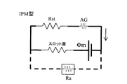
- FIG. 23 is an equivalent magnetic circuit diagram of the IPM rotor.
- ⁇ m is the magnetic flux
- Rst is the magnetic resistance of the stator
- AG is the air gap
- Rrt is the magnetic resistance of the rotor
- Ra is the magnetic resistance of the gap in the d-axis circuit.
- the magnetic flux ⁇ m is shunted, and two magnetic circuits, a magnetic circuit that passes through the boss portion of the Landel rotor core and a magnetic circuit that passes through the stator core, It is formed.
- the d-axis circuit is a gap (dashed line portion). Therefore, the magnetic resistance Ra is very high and the inductance Lrt is very low. This is the cause of the torque difference at the time of loading between the Landell rotor with magnet and the IPM rotor. That is, if the magnetic resistance Rrt is very high at the time of load and the inductance Lrt is very low, the same level of torque as that of the IPM rotor can be output even with a Landell rotor with magnet.
- the present inventor conducted research based on the above findings. As a result, the present inventor has found that a situation in which the same level of torque as that of the IPM rotor can be output by using the field current If in the magnet Landell rotor.
- the resistance corresponding to the field core (rotor core) is high, and the resistance of the stator core is low. Therefore, in the Landell type rotor with magnet, if the resistance value of the field core (Landel type rotor core) is increased when the field current If is applied, and the resistance value of the field core becomes larger than the resistance value of the stator core, the IPM type The situation is the same as for the rotor.
- the rotor inductance is Lrt
- the stator inductance is Lst
- the magnetic resistance of the magnetic flux flowing through the rotor is Rrt
- the magnetic resistance of the magnetic flux flowing through the stator is Rst.
- Lrt when a load is applied to the rotor, Lrt ⁇ Lst (Expression 1) or Rrt> Rst (Expression 2).
- the residual magnetic flux density of the magnet is Br
- the cross-sectional area of each magnetic pole of the magnet is Am
- the magnetic flux density of the stator is Bs
- the cross-sectional area of the rotor is Ar.
- Rrt> Rst 2 ⁇ Br ⁇ Am> Bs ⁇ Ar (conditions where the back electromotive force is low).
- a first rotating electrical machine that is an aspect of the technology of the present disclosure includes an annular stator (20) in which an armature winding (25) is wound around a stator core (21), and a radial direction on the inner peripheral side of the stator. And a rotor (30) disposed opposite to each other.
- the rotor has a cylindrical boss portion (321, 321a, 321b) and a plurality of claw-shaped magnetic pole portions (323, 323a) which are arranged on the outer peripheral side of the boss portion and have magnetic poles having different polarities alternately in the circumferential direction.
- the permanent magnets (34, 34A) are arranged such that the easy magnetization axis is oriented in the circumferential direction and the magnetic poles are formed so as to coincide with the polarities alternately appearing in the claw-shaped magnetic pole portions by the magnetomotive force of the field winding. And comprising.
- the magnetic flux formed by the magnetomotive force of the field windings flows through the boss portion, the pair of claw-shaped magnetic pole portions, and the stator core, and the permanent magnet At least a part of the magnet magnetic circuit (38, 39) through which the magnetic flux formed by the magnetic force flows is shared.
- the q-axis is formed by the permeance Prt of the d-axis magnetic circuit and the current flowing through the armature winding and shifted by 90 ° in electrical angle from the d-axis.
- the relationship with the permeance Pst of the q-axis magnetic circuit (37) passing through is set such that Pst> Prt.
- the permanent magnet disposed between the claw-shaped magnetic pole portions adjacent in the circumferential direction causes the magnetic magnetic circuit in which the magnetic flux linked to the stator flows, and the rotor through the boss portion.
- Two magnet magnetic circuits are formed, a magnet magnetic circuit in which the flow of magnetic flux is completed.
- the magnet magnetic flux that flows through the magnet magnetic circuit that passes through the boss portion and is completed in the rotor flows in the opposite direction to the magnetic flux of the d-axis magnetic circuit. For this reason, the resistance becomes large and difficult to flow. Therefore, in the first rotating electrical machine, the relationship between the permeance Prt of the d-axis magnetic circuit and the permeance Pst of the q-axis magnetic circuit is set to satisfy Pst> Prt. Therefore, among the two magnet magnetic circuits, the magnet magnetic flux of the magnet magnetic circuit through which the magnetic flux interlinking with the stator flows can be increased. As a result, the magnetic flux can be effectively used to greatly improve the power generation capacity.
- a second rotating electric machine having a brushless structure which is an aspect of the technology of the present disclosure, includes an annular stator (20) in which an armature winding (25) is wound around a stator core (21), and an inner portion of the stator.
- the rotor (50) arrange
- the housing has a boss portion (17) that is disposed on the inner peripheral side of the rotor and on which the field winding (53) that generates a magnetomotive force when energized is wound on the outer peripheral side.
- the rotor is adjacent to the field core (52) having a plurality of magnetic pole portions (52n, 52s) disposed on the outer peripheral side of the field winding and having magnetic poles having different polarities alternately in the circumferential direction.
- the permanent magnet (54) is arranged such that the easy axis of magnetization is arranged in the circumferential direction between the magnetic pole portions to be aligned, and the magnetic poles are formed so as to coincide with the polarities alternately appearing in the magnetic pole portions by the magnetomotive force of the field winding. And).
- the magnetic flux formed by the magnetomotive force of the field winding is generated by the d-axis magnetic circuit (56) flowing via the boss portion, the pair of magnetic pole portions, and the stator core, and the magnetic force of the permanent magnet. At least a part of the formed magnetic circuit (58, 59) is shared.
- the q-axis is formed by the permeance Prt of the d-axis magnetic circuit and the current flowing through the armature winding and is shifted by 90 ° in electrical angle from the d-axis.
- the relationship with the permeance Pst of the q-axis magnetic circuit (57) passing through is set such that Pst> Prt.
- the permanent magnet disposed between the magnetic pole portions adjacent in the circumferential direction passes through the boss portion and the magnet magnetic circuit through which the magnetic flux interlinked with the stator flows.
- Two magnet magnetic circuits that is, a magnet magnetic circuit that completes the flow of magnetic flux, are formed.
- the magnet magnetic flux that flows through the magnet magnetic circuit that passes through the boss portion and is completed in the rotor flows in the opposite direction to the magnetic flux of the d-axis magnetic circuit. For this reason, the resistance becomes large and difficult to flow. Therefore, in the second rotating electrical machine, the relationship between the permeance Prt of the d-axis magnetic circuit and the permeance Pst of the q-axis magnetic circuit is set to satisfy Pst> Prt. Therefore, the magnet magnetic flux of the magnet magnetic circuit through which the magnetic flux linked to the stator flows out of the two magnet magnetic circuits increases. As a result, the magnetic flux can be effectively used to greatly improve the power generation capacity.
- brushless rotating electrical machines do not need to be restricted by brush current. Therefore, the current value of the field current If restricted by the brush can be increased. As a result, even in a brushless rotating electric machine, the field circuit can be saturated and the magnet magnetic force can be used effectively. Moreover, the electric circuit which supplies a field current to the field winding is independent. Therefore, in the centrifugal strength, which is a weak point of the Landell rotor with magnet, it is not necessary to receive the centrifugal force of the electric circuit behind the magnetic pole portion. Thereby, the stress by centrifugal force can be reduced.
- a third rotating electric machine that is an aspect of the technology of the present disclosure includes an annular stator (20) in which an armature winding (25) is wound around a stator core (21), and an inner peripheral side of the stator. And a rotor (30) arranged to be rotatable in the radial direction.
- the rotor has a cylindrical boss portion (321, 321a, 321b) and a plurality of claw-shaped magnetic pole portions (323, 323a) which are arranged on the outer peripheral side of the boss portion and have magnetic poles having different polarities alternately in the circumferential direction.
- the surface area of the outer peripheral surface of the claw-shaped magnetic pole portion is As
- the cross-sectional area of the iron core extending in the axial direction per pair of NS magnetic poles of the boss portion is Ab.
- the relationship between the surface area As of the outer peripheral surface of the claw-shaped magnetic pole part and the core cross-sectional area Ab extending in the axial direction per pair of NS magnetic poles of the boss part is 0.
- the range is set to 9 ⁇ As / Ab ⁇ 1.7. Therefore, among the magnetic circuit formed by the permanent magnets arranged between the claw-shaped magnetic pole portions adjacent in the circumferential direction, the magnetic flux of the magnetic magnetic circuit through which the magnetic flux linked to the stator flows can be increased. As a result, the magnetic flux can be effectively used to greatly improve the power generation capacity.
- claw-shaped magnetic pole part was conventionally used for the purpose of the rectification
- the permanent magnet disposed between the claw-shaped magnetic pole portions is used like the permanent magnet of the IPM rotor. Thereby, not leakage prevention etc. but magnetic flux can be increased. That is, it can function as a torque-up source or an output-up source.
- a fourth rotating electric machine having a brushless structure that is an aspect of the technology of the present disclosure includes an annular stator (20) in which an armature winding (25) is wound around a stator core (21), and an inner portion of the stator.
- the rotor (50) arrange
- the housing is disposed on the inner peripheral side of the rotor, and has a boss portion (17) around which a field winding (53) that generates a magnetomotive force when energized is wound on the outer peripheral side.
- the rotor is adjacent to the field core (52) having a plurality of magnetic pole portions (523h, 523i) disposed on the outer peripheral side of the field winding and having magnetic poles having different polarities alternately in the circumferential direction.
- the permanent magnet (54) is arranged such that the easy axis of magnetization is arranged in the circumferential direction between the magnetic pole portions to be aligned, and the magnetic poles are formed so as to coincide with the polarities alternately appearing in the magnetic pole portions by the magnetomotive force of the field winding.
- the surface area of the outer peripheral surface of the magnetic pole part is As
- the cross-sectional area of the iron core extending in the axial direction around the pair of NS magnetic poles of the boss part is Ab.
- the relationship between the surface area As and the cross-sectional area Ab is set in a range where 0.9 ⁇ As / Ab ⁇ 1.7.
- the relationship between the surface area As of the outer peripheral surface of the magnetic pole portion and the core cross-sectional area Ab extending in the axial direction per pair of NS magnetic poles of the boss portion is 0.9 ⁇
- the range is set to As / Ab ⁇ 1.7. Therefore, the magnet magnetic flux of the magnet magnetic circuit through which the magnetic magnetic flux linked to the stator flows among the magnetic magnetic circuits formed by the permanent magnets arranged between the magnetic pole portions adjacent in the circumferential direction can be increased. As a result, the magnetic flux can be effectively used to greatly improve the power generation capacity.
- positioned between magnetic pole parts was conventionally used for the purpose of the rectification
- the permanent magnet disposed between the magnetic pole portions is used like the permanent magnet of the IPM rotor.
- magnetic flux can be increased. That is, it can function as a torque-up source or an output-up source.
- FIG. 1st Embodiment It is a figure for demonstrating the measuring method of the permeance in 1st Embodiment. It is a diagram which shows the measurement result of the permeance of the rotary electric machine which concerns on the comparative example 1.
- FIG. It is a diagram which shows the measurement result of the permeance of the rotary electric machine which concerns on 1st Embodiment. It is a figure for demonstrating the measuring method of the permeance of a rotor in 1st Embodiment. It is a figure for demonstrating the measuring method of the permeance of a rotor in 1st Embodiment. It is a figure for demonstrating the measuring method of the permeance of a stator in 1st Embodiment.
- FIG. 28 is a cross-sectional view in the axial direction of the rotating electrical machine according to the second embodiment, corresponding to a plane cut along the line XXIV-XXIV in FIGS. 25 and 27. It is a perspective view of the rotary electric machine which concerns on 2nd Embodiment.
- the rotating electrical machine according to the first embodiment will be described with reference to FIGS.
- the rotating electrical machine according to the present embodiment is a vehicle AC generator that is mounted on a vehicle and used as a generator.
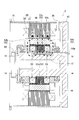
- the vehicle alternator 1 of this embodiment includes a housing 10, a stator 20, a rotor 30, a field winding power feeding device 40, a rectifier 45, and the like.
- the housing 10 includes a bottomed cylindrical front housing 11 and a rear housing 12 each having an open end.
- the front housing 11 and the rear housing 12 are fastened with bolts 13 in a state where the openings are joined to each other.
- the stator 20 has an annular stator core 21 and an armature winding 25.
- the stator core 21 has a plurality of slots 22 and teeth 23 (see FIG. 7) arranged in the circumferential direction.
- the armature winding 25 is composed of a three-phase winding wound around the slot 22 of the stator core 21.
- the stator 20 is fixed to the inner peripheral surfaces of the peripheral walls of the front housing 11 and the rear housing 12 while being sandwiched in the axial direction.
- the rotor 30 has a rotating shaft 31, a Landel-type field core 32, a field winding 33, and a plurality of permanent magnets 34.
- the rotating shaft 31 is rotatably supported with respect to the housing 10 via a pair of bearings 14.
- the field core 32 includes a pair of pole cores 32a and 32b fitted and fixed to the outer periphery of the rotary shaft 31.
- the field winding 33 is wound around the outer periphery of the boss portion 321 of the field core 32.
- the permanent magnet 34 is disposed between the claw-shaped magnetic pole portions 323 adjacent in the circumferential direction of the field core 32.
- the rotor 30 is provided so that the field core 32 can rotate in the radial direction on the inner peripheral side of the stator 20.
- the rotor 30 is rotationally driven by an engine (not shown) mounted on the vehicle via a pulley 35 fixed to the front end portion of the rotating shaft 31.
- the field core 32 includes a first pole core 32 a and a second pole core 32 b.
- the first pole core 32a is fixed to the front side (left side in FIG. 1) of the rotating shaft 31.
- the second pole core 32b is fixed to the rear side (right side in FIG. 1) of the rotary shaft 31.
- the first pole core 32a includes a cylindrical first boss portion 321a, a first disk portion 322a, and a first claw-shaped magnetic pole portion 323a.
- the first boss portion 321 a causes the field magnetic flux to flow in the axial direction on the radially inner side of the field winding 33.
- the first disk portion 322a extends radially outward from the axial front end of the first boss portion 321a at a predetermined circumferential pitch, and causes field magnetic flux to flow in the radial direction.
- the first claw-shaped magnetic pole portion 323a extends on the outer peripheral side of the first boss portion 321a in the axial direction so as to surround the field winding 33 from the tip of the first disk portion 322a, and exchanges magnetic flux with the stator core 21. do.
- the second pole core 32b has the same shape as the first pole core 32a. However, the second boss part of the second pole core 32b is numbered 321b, the second disk part 322b, and the second claw-shaped magnetic pole part 323b.
- the first and second pole cores 32a and 32b are made of a soft magnetic material.
- the field core 32 of this embodiment is formed of two types of materials having different saturation magnetic flux densities Bs. That is, each claw-shaped magnetic pole portion 323 is formed of a material having a high saturation magnetic flux density Bs.
- the boss part 321 and the disk part 322 other than the claw-shaped magnetic pole part 323 are made of a material having a low saturation magnetic flux density Bs.
- Examples of the material having a high saturation magnetic flux density Bs include materials having a carbon content of about 0.1% such as S10C (JIS regulations).
- Examples of the material having a low saturation magnetic flux density Bs include a material having a large amount of carbon such as S45C (JIS regulations). Note that the saturation magnetic flux density Bs of SUS430 (JIS regulations), electrical steel sheets, and the like is lower than that of S10C.
- the material with a low magnetic permeability is employ
- An example of a material having a high magnetic permeability is permalloy. Although iron to which nickel cobalt is added is also mentioned, it cannot be applied because the saturation magnetic flux density Bs is high.
- the first pole core 32a and the second pole core 32b are formed such that the first claw-shaped magnetic pole portions 323a and the second claw-shaped magnetic pole portions 323b face each other alternately, and the rear end surface in the axial direction of the first pole core 32a and the second pole core 32b.
- the first claw-shaped magnetic pole portions 323a of the first pole core 32a and the second claw-shaped magnetic pole portions 323b of the second pole core 32b are alternately arranged in the circumferential direction.
- the first and second pole cores 32a and 32b each have eight claw-shaped magnetic pole portions 323.
- a 16-pole (N pole: 8, S pole: 8) Landell type rotor core is formed.
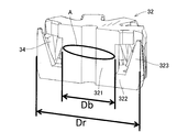
- the outer diameter of the boss portion 321 of the field core 32 is Db (hereinafter also referred to as “boss portion outer diameter Db”), and the rotor 30 (field core 32). ) Is designated as Dr (hereinafter also referred to as “rotor outer diameter Dr”).
- Db the outer diameter of the boss portion 321 of the field core 32
- Dr the rotor 30
- Dr the relationship between the boss part outer diameter Db and the rotor outer diameter Dr is set in a range where 0.46 ⁇ Db / Dr ⁇ 0.53. The relationship between the boss part outer diameter Db and the rotor outer diameter Dr will be described in detail later.
- the surface area of the outer peripheral surface of the claw-shaped magnetic pole portion 323 is As (hereinafter also referred to as “claw-shaped magnetic pole portion surface area As”), and the core cross-sectional area (iron core) extending in the axial direction around a pair of NS magnetic poles of the boss portion 321.
- the area of the cross section perpendicular to the extending direction (axial direction) is Ab (hereinafter referred to as “boss section cross-sectional area Ab”).
- the relationship between the claw-shaped magnetic pole part surface area As and the boss part cross-sectional area Ab is set in a range of 0.9 ⁇ As / Ab ⁇ 1.7.
- the boss section cross-sectional area Ab is A / P when the total cross-sectional area of the cylindrical boss section 321 is A and the number of pole pairs of the rotating electrical machine is P. It is represented by
- the claw-shaped magnetic pole part surface area As will be defined.
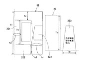
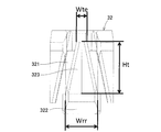
- the circumferential width of the root of the claw-shaped magnetic pole part 323 or the disk part 322 is Wrr
- the circumferential width of the tip of the claw-shaped magnetic pole part 323 is Wte.
- the axial height of the claw-shaped magnetic pole part 323 is denoted by Ht.
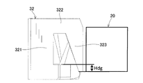
- a range where the axial length of the stator core 21 and the axial thickness of the disk portion 322 overlap in the radial direction on the opposing surfaces of the rotor 30 and the stator 20 facing in the radial direction is referred to as a disk guide and is referred to as Hdg.
- the claw-shaped magnetic pole part surface area As (Wte + Wrr) ⁇ Ht / 2 + Hdg ⁇ Wrr.
- the circumferential width W is measured by a linear distance without considering the curvature. The relationship between the claw-shaped magnetic pole part surface area As and the boss part cross-sectional area Ab will be described in detail later.
- the field winding 33 is wound around the outer periphery of the first and second boss portions 321a and 321b of the first and second pole cores 32a and 32b while being insulated from the field core 32. It is surrounded by the second claw-shaped magnetic pole portions 323a and 323b.
- the field winding 33 generates a magnetomotive force in the boss portion 321 when a field current If is supplied from a field current control circuit (not shown).
- a field current control circuit not shown.
- magnetic poles having different polarities are formed on the first claw-shaped magnetic pole portion 323a and the second claw-shaped magnetic pole portion 323b of the first and second pole cores 32a and 32b, respectively. That is, the first claw-shaped magnetic pole part 323a is magnetized to one polarity of the NS magnetic poles, and the second claw-shaped magnetic pole part 323b is magnetized to the other polarity of the NS magnetic poles.
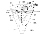
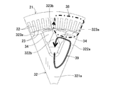
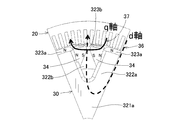
- the d-axis magnetic circuit 36 is generated by the magnetic flux passing through the boss portion 321 of the field core 32 and the pair of first and second claw-shaped magnetic pole portions 323a and 323b. (Shown by broken lines in FIGS. 7 and 8) is formed.
- the d-axis magnetic circuit 36 enters the first claw-shaped magnetic pole portion 323a of the field core 32 from the d-axis tooth 23 of the stator core 21, and the first disk portion 322a, the first boss portion 321a, the second boss portion 321b, 2 It passes through the disk portion 322b and the second claw-shaped magnetic pole portion 323b.
- the d-axis magnetic circuit 36 is a magnetic circuit that generates a counter electromotive force of the rotor 30.
- a current flows through the armature winding 25 by the magnetic flux interlinking with the stator 20 of the d-axis magnetic circuit 36 and the first magnet magnetic circuit 38 described later.
- a q-axis magnetic circuit 37 (shown by a solid line in FIG. 7) is formed.
- the q-axis magnetic circuit 37 is a magnetic circuit formed by a magnetic flux passing through the q-axis at a position shifted by 90 ° in electrical angle from the d-axis of the stator core 21.
- the relationship between the permeance Prt of the d-axis magnetic circuit 36 and the permeance Pst of the q-axis magnetic circuit 37 is set to satisfy Pst> Prt.
- the ratio (Lq / Ld) between the q-axis inductance Lq and the d-axis inductance Ld is defined as the salient pole ratio ⁇ .
- the salient pole ratio ⁇ of the conventional Landel rotor is ⁇ 1.
- the salient pole ratio ⁇ of the conventional IPM rotor is ⁇ 2-4.
- the permeance ratio between the d-axis magnetic circuit 36 and the q-axis magnetic circuit 37 is set as described above.
- the aspect at the time of the load to the rotor 30 is brought close to an IPM type rotor also in a Landel type rotor.
- the salient pole ratio ⁇ can be 2 or more.
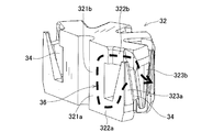
- the first claw-shaped magnetic pole portions 323 a and the second claw-shaped magnetic pole portions 323 b that are alternately arranged in the circumferential direction are vertically elongated in the axial direction.
- a gap extending in the direction is formed.
- One permanent magnet 34 is disposed in each gap.
- Each permanent magnet 34 has a rectangular parallelepiped shape, the easy magnetization axis is directed in the circumferential direction, and the magnetic pole portions on both sides in the circumferential direction are circumferential directions of the first and second claw-shaped magnetic pole portions 323a and 323b.
- the first and second claw-shaped magnetic pole portions 323a and 323b are held in contact with the side surfaces, respectively. That is, each permanent magnet 34 has a magnetic pole formed so as to coincide with the polarities alternately appearing in the first and second claw-shaped magnetic pole portions 323a and 323b by the magnetomotive force of the field winding 33.
- the permanent magnet 34 is arranged in this way.
- two first and second magnet magnetic circuits 38 and 39 are formed in each permanent magnet 34.
- the first magnet magnetic circuit (indicated by a one-dot chain line in FIG. 10) 38 is a magnetic circuit through which a magnetic flux interlinking with the stator 20 flows.
- a second magnet magnetic circuit (indicated by a double line in FIG. 10) 39 is a magnetic circuit through which a magnetic flux that completes in the rotor 30 passes through the boss portion 321a and the disk portions 322a and 322b.
- the second magnet magnetic circuit 39 passing through the boss portion 321 is a magnetic circuit through which a magnet magnetic flux that is ineffective for the stator 20 flows.
- the 1st magnet magnetic circuit 38 is a magnetic circuit which the magnet magnetic flux which interlinks with the stator 20 and becomes a counter electromotive force and a torque flows.
- the first magnet magnetic circuit 38 and the above-described d-axis magnetic circuit 36 are magnetic circuits from the second claw-shaped magnetic pole portion 323b to the first claw-shaped magnetic pole portion 323a via the stator 20. Sharing.
- the second magnet magnetic circuit 39 and the d-axis magnetic circuit 36 are magnetic circuits of the first and second boss portions 321a and 321b of the rotor 30 and the first and second disk portions 322a and 322b. Sharing.
- the cross-sectional area of the iron core extending in the axial direction around the pair of NS magnetic poles of the boss portion 321 is Ab
- the magnetic flux density when a field of 5000 [A / m] is applied to the boss portion 321 is defined as the magnetic flux density.
- B50 the residual magnetic flux density of the permanent magnet 34 disposed between the claw-shaped magnetic pole portions 323
- the cross-sectional area of the surface serving as the magnetic pole of the permanent magnet 34 is Am.
- it is set so as to satisfy the relationship of 2 ⁇ Br [T] ⁇ Am [mm 2 ] ⁇ B50 [T] ⁇ Ab [mm 2 ]. The setting of this relationship will be described in detail later.
- the field winding power supply device 40 is a device for supplying power to the field winding 33.
- the field winding power supply apparatus 40 includes a pair of brushes 41, a pair of slip rings 42, a regulator 43, and the like.
- the pair of slip rings 42 are fitted and fixed to one axial end of the rotating shaft 31 (the right end in FIG. 1).
- the pair of brushes 41 are slidably disposed with their radially inner ends pressed against the surface of the slip ring 42.
- the pair of brushes 41 supplies power to the field winding 33 via the slip ring 42.
- the regulator 43 is a device that adjusts the output voltage of the vehicular AC generator 1 by controlling the field current If flowing in the field winding 33.
- the rectifier 45 is electrically connected to the armature winding 25.
- the rectifier 45 is a device that rectifies an alternating current output from the armature winding 25 into a direct current.
- the rectifier 45 includes a plurality of diodes (rectifier elements) and the like.
- the vehicular AC generator 1 having the above configuration, when the rotational force from the engine is transmitted to the pulley 35 via a belt or the like, the rotor 30 rotates in a predetermined direction together with the rotary shaft 31. In this state, the automotive alternator 1 applies an excitation voltage from the brush 41 to the field winding 33 of the rotor 30 via the slip ring 42. As a result, the first and second claw-shaped magnetic pole portions 323 a and 323 b of the first and second pole cores 32 a and 32 b are excited, and NS magnetic poles are alternately formed along the rotational circumferential direction of the rotor 30.
- the vehicle alternator 1 having the above configuration is characterized in that the boss portions 321a and 321b of the pole cores 32a and 32b are narrower or the disk portions 322a and 322b of the pole cores 32a and 32b are thinner than the conventional one. Therefore, in the vehicle alternator 1, more field windings 33 can be wound as much as the boss portions 321a and 321b become thinner or as the disk portions 322a and 322b become thinner. Alternatively, in the vehicular AC generator 1, the wire constituting the field winding 33 can be made thicker by the amount that the boss portions 321a and 321b are thinner or the disk portions 322a and 322b are thinner.
- the volume ratio of the field winding 33 increases in the rotor 30 including the field core 32 and the field winding 33.
- the field winding 33 is composed of a wire made of copper or the like, and has better thermal conductivity than the field core 32 made of iron or the like. That is, in the rotor 30 including the field core 32 and the field winding 33, the volume ratio of the field winding 33 having better thermal conductivity than the field core 32 is increased. Therefore, in the vehicular AC generator 1, the heat dissipation of the rotor 30 can be improved. Thereby, in AC generator 1 for vehicles, it becomes possible to cool rotor 30 by air cooling.
- the total amount of the material constituting the pole cores 32a and 32b can be reduced by the amount of thinning of the boss portions 321a and 321b or the amount of thinning of the disk portions 322a and 322b. Therefore, the pressurizing force required when forming by forging is reduced.
- hub part 321 is made into a different body, it becomes easy to shape
- the rotating electrical machine according to the present disclosure can be replaced with an alternator, a starter, or the like that is connected to a power source of 12 to 48 [V], including a tolerance range of 6 [V] to 60 [V]. It is intended for electrical machinery. Therefore, in the rotating electrical machine of the present disclosure, the counter electromotive force should not be output as large as the IPM rotor.
- Bs [T] is the saturation magnetic flux density of the field core 32.
- Br [T] cannot be sufficiently absorbed unless the relative permeability is sufficiently high.
- Bs [T] of the field core 32 is adopted, here, the value of B50 [T] that is generally used is considered.
- the magnetomotive force applied to the field core 32 is 2500 AT or less. Therefore, the thickness [mm] and the holding force [Hc] of the permanent magnet 34 are designed with a safety factor of about 5000 A or more.
- the Br value and the Hc value vary somewhat depending on the temperature considered by the designer. However, it is necessary that there is a range of 5000 A in any temperature range of ⁇ 40 to 160 [° C.] expected to be used.
- the credibility of the present disclosure which is defined by the permanent magnet 34 designed at about 5000 AT and the value of B50 that is the magnetic flux density at 5000 A, is very high.
- the relative permeability before this is 30 or more and is sufficiently high.
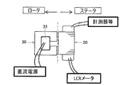
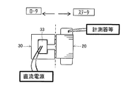
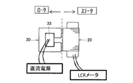
- 11 and 12 are explanatory views schematically showing the N pole and S pole of the rotor 30, the field winding 33, and the stator 20.
- a DC power source is connected to the field winding 33.
- a measuring instrument or the like connecting the LCR meter and the voltage probe is connected to an arbitrary terminal of the stator 20 that is conducting.
- the measuring instrument or the like may be anything that can measure voltage like an oscilloscope. Therefore, the measuring instrument or the like may be a combination of a voltage probe and any voltage measuring instrument.
- the positional relationship between the stator 20 and the rotor 30 is preferably excitation toward the q axis so that the stator 20 does not weaken the center of the d axis of the rotor 30 and does not perform field excitation.
- the field weakening is applied to the field circuit of the rotor 30 during the field weakening excitation, which may prevent correct measurement.
- the field weakening effect is sin 15 ° ⁇ 0.25 in the excitation magnetic flux if the electric angle is within a range of about 15 ° where the field weakening effect is low.
- the data is in a positional relationship where the maximum inductance can be obtained within the range of electrical angle ⁇ 15 ° from the q-axis energization, it can be trusted to some extent. Further, in order to omit the magnet magnetic flux, it is preferable to perform measurement with the permanent magnet 34 excluded or sufficiently demagnetized.
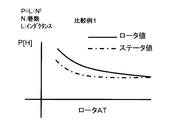
- FIG. 13 is a diagram showing measurement results of permeance of the rotating electrical machine according to Comparative Example 1.
- FIG. 14 is a diagram showing measurement results of permeance of the rotating electrical machine according to the present embodiment.
- the comparative example 1 is intended for the rotating electrical machine defined by the mathematical formula described in Patent Document 1 described above.
- the permeance of the rotor 30 is higher in the no-load state.
- the permeance is the same as that of the stator 20.
- the stator 20 in the no-load state has lower permeance than the rotor 30 due to a magnetic barrier, a magnet, and the like existing on the q axis.
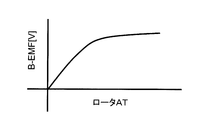
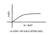
- the field winding 33 is fielded by a DC power source, and the field circuit (d-axis magnetic circuit 36) is excited. At this time, if the rotor 30 is rotated, a counter electromotive force is generated. When an arbitrary number of revolutions is determined and the counter electromotive force is measured by operating at a constant speed, the counter electromotive force increases according to the number of revolutions of the rotor 30.
- the back electromotive force of the rotor 30 has a saturation tendency in the change of the inclination together with the saturation of the field circuit.
- the inductance L_0 (el zero) at no load is defined as a magnetic flux change between 0AT and 0 + XAT.
- the inductance at the time of 100AT excitation is described as L_100 (El Hyaku).
- the exciting current I is (inflow current value of DC power supply) ⁇ (the number of turns of the field winding 33 wound around the boss portion 321).
- L_0 (V_x ⁇ V_0) / (I_x ⁇ I_0)
- the inductance at 100AT excitation is as follows.
- L_100 (V_200 ⁇ V_100) / (200 ⁇ 100)
- the field winding 33 is fielded by a DC power source, and the field circuit (d-axis magnetic circuit 36) is excited.
- the disk pole type rotating electric machine can use up the axial length of the stator by generating a magnetic flux at a location (boss) different from the opposed surfaces of the stator and rotor and passing the magnetic flux in the axial direction.
- a claw pole type rotating electrical machine as illustrated in FIG. 4, the cross-sectional area Ab of the boss part, the cross-sectional area Ad of the disk part 322 (hereinafter also referred to as “disk part cross-sectional area Ad”), and a claw shape.
- Magnetic flux is output with the base cross-sectional area At (hereinafter also referred to as “claw-shaped magnetic pole part cross-sectional area At”) of the magnetic pole part 323 substantially constant.
- each claw has a magnetic field generated in the boss portion 321 by energizing a field winding 33 (not shown in FIG. 4) wound around the outer periphery of the boss portion 321. It has an opposing surface area that can pass the magnetic flux (an appropriate opposing surface area with the stator 20 according to the boss section cross-sectional area Ab).
- the magnet magnetic flux passes through the rotor 30 against the field magnetic flux (d-axis magnetic circuit 36) (second magnet magnetic circuit 39 in FIG. 10). And a route around the stator 20 side (first magnet magnetic circuit 38 in FIG. 10). That is, the three points of the boss section cross-section Ab, the disk section cross-section Ad, and the claw-shaped magnetic pole section cross-section At shown in FIG. At the same time, it is necessary to consider the electromotive voltage while satisfying the relationship of Ab ⁇ B50 ⁇ 2 ⁇ Am ⁇ Br. At this time, the boss portion outer diameter Db (see FIG. 3) is reduced. Therefore, the arrangement space of the field winding 33 is increased, and the amount of heat generated should be reduced.
- the ratio between the rotor outer diameter Dr and the boss portion outer diameter Db should be uniquely determined.
- the boss portion outer diameter Db can be calculated from the magnet flux and the field flux that flow backward.
- the current air cooling capability is taken into consideration, and the resistance value of the field winding 33 is 0.1 to 1.0 [Ohm] for a motor, and 1.0 to 3 for a generator. Needless to say, 0 [Ohm].
- Ab ⁇ B50-2 ⁇ Am ⁇ Bd ⁇ (Prt / (Pst + Prt)) Abopt (Ideal value of Ab)
- the claw-shaped magnetic pole part surface area As is a value that allows the field magnetic flux to sufficiently flow.
- the conventional permanent magnet mainly played a role of preventing leakage magnetic flux between the claw-shaped magnetic pole portions. Therefore, the claw-shaped magnetic pole part surface area As of the randel type rotating electrical machine with a neodymium magnet in circulation is distributed in a range of values according to the boss part cross-sectional area Ab. That is, As is distributed in a range of values based on Ab satisfying Ab ⁇ 0.8 to Ab ⁇ 1.2.
- the calculation formula of Bd ⁇ (Pst / (Pst + Prt)) can be used effectively.
- the claw-shaped magnetic pole part surface area As needs a dimension for passing the magnetic flux of the rotor 30 to which [As Bd ⁇ Am + Ab ⁇ Bs] should be an optimum value to the stator 20, and Ab ⁇ 1.2. Should be bigger than.
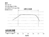
- FIG. 20 shows the ratio (Db / Dr) of the boss portion outer diameter Db and the rotor outer diameter Dr on the horizontal axis, and the amount of interlinkage magnetic flux when the stator 20 is loaded on the vertical axis.
- the amount of magnetic flux linkage has a peak in the vicinity of Db / Dr of 0.51, and a range of 0.46 to 0.53 of Db / Dr is a preferable range.
- Db / Dr range of the prior art Patent Document 1 is about 0.54 to 0.595, which is not different from the preferred range of Db / Dr of the present disclosure.
- the ratio (As / Ab) between the claw-shaped magnetic pole part surface area As and the boss section sectional area Ab is taken on the vertical axis
- the ratio (Db / Dr) between the boss part outer diameter Db and the rotor outer diameter Dr is taken on the horizontal axis.
- Two magnet magnetic circuits, that is, a second magnet magnetic circuit 39 through which a magnetic flux that completes in the rotor 30 passes through the boss portion 321, are formed.
- the relationship between the permeance Prt of the d-axis magnetic circuit 36 and the permeance Pst of the q-axis magnetic circuit 37 is set to satisfy Pst> Prt. Therefore, among the two magnet magnetic circuits 38 and 39, the magnet magnetic flux of the first magnet magnetic circuit 38 through which the magnetic flux linked to the stator 20 flows increases. Thereby, in this embodiment, a magnetic flux can be used effectively and a power generation capability can be improved significantly.
- the cross-sectional area of the boss part is Ab
- the magnetic flux density when a 5000 [A / m] field of the boss part 321 is applied is B50.
- the residual magnetic flux density of the permanent magnet 34 is Br
- the cross-sectional area of the surface serving as the magnetic pole of the permanent magnet 34 is Am.
- the relationship of 2 ⁇ Br [T] ⁇ 2 ⁇ Am [mm 2 ] ⁇ B50 [T] ⁇ Ab [mm 2 ] is satisfied.
- the magnetic force generated by the permanent magnet 34 can be absorbed by the d-axis magnetic circuit 36. Therefore, the counter electromotive force can be lowered, and the generated power in the high-speed rotation state when no current is supplied can be suppressed.
- the salient pole ratio ⁇ which is the ratio (Lq / Ld) between the q-axis inductance Lq and the d-axis inductance Ld, can be made 2 or more. Thereby, in this embodiment, the reluctance torque of the same grade as an IPM type
- the relationship between the claw-shaped magnetic pole part surface area As and the boss part cross-sectional area Ab is set in a range where 0.9 ⁇ As / Ab ⁇ 1.7. That is, it means that the claw-shaped magnetic pole part surface area As is larger than the boss part cross-sectional area Ab.
- the permanent magnet 34 conventionally used for the purpose of rectifying the magnetic flux between the adjacent claw-shaped magnetic pole portions 323 and preventing leakage is used like an IPM rotor in this embodiment. Thereby, not leakage prevention but magnetic flux can be increased. That is, it can function as a torque-up source or an output-up source.
- the relationship between the boss portion outer diameter Db and the rotor outer diameter Dr is set in a range of 0.46 ⁇ Db / Dr ⁇ 0.53.
- the boss section cross-sectional area Ab is a range determined in consideration of the reaction of the magnet magnetic force to the magnetic force of the boss portion to the maximum.
- the magnetic force of the boss portion 321 that can repel the reaction caused by the magnet magnetic force at that time acts on the field core 32.
- the claw-shaped magnetic pole part cross-sectional area At can transmit the total magnetic force of the boss part 321 and the total magnetic force of the magnet to the stator 20 side.
- the residual magnetic flux density Br of the permanent magnet 34 is 1 [T] or more.
- the magnet magnetic force is a bonded magnet of neodymium iron boron, a plastic molded magnet by injection molding of samarium iron nitrogen or the like, the demagnetizing field to the field core 32 cannot be sufficiently supplied in many cases. That is, in order to prepare the cross-sectional area of the magnet, there is often a case where the space of the field winding 33 is reduced. Therefore, the above-described functions and effects are effectively exhibited particularly when the residual magnetic flux density Br of the permanent magnet 34 is 1 [T] or more.
- the portion of the field core 32 where the d-axis magnetic circuit 36 is formed is formed of two types of materials having different saturation magnetic flux densities Bs.
- the claw-shaped magnetic pole part 323 is formed of a material having a high saturation magnetic flux density Bs, and the portions other than the claw-shaped magnetic pole part 323 are formed of a material having a low saturation magnetic flux density Bs. Accordingly, in the present embodiment, the boss portion 321 immediately saturates the magnetic flux and easily changes to the behavior of the magnetic flux characteristics of the IPM rotor. Therefore, the improvement in power generation capacity can be achieved more reliably.
- the material having a low saturation magnetic flux density Bs used in a portion other than the claw-shaped magnetic pole portion 323 has a higher magnetic permeability than a material having a high saturation magnetic flux density Bs. Therefore, the effect of absorbing electromotive force is enhanced when no load is applied to the rotor 30.
- a rotating electrical machine according to the second embodiment will be described with reference to FIGS.
- the rotating electrical machine according to this embodiment is a vehicle AC generator similar to that of the first embodiment.
- the rotating electrical machine according to the present embodiment is different from the first embodiment in that it has a brushless structure.
- different points and important points will be described.
- symbol is used and detailed description is abbreviate
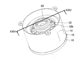
- the vehicle alternator 2 of this embodiment includes an annular stator 20, a rotor 50, a housing 10, and the like as illustrated in FIGS. 24, 25, and 26.
- the vehicle alternator 2 has a brushless structure as described above.
- the stator 20 is formed by winding an armature winding 25 around a stator core 21.
- the rotor 50 is disposed on the inner peripheral side of the stator 20 so as to face the radial direction.
- the housing 10 accommodates and supports the stator 20 and the rotor 50 therein.
- the housing 10 includes a hollow cylindrical tubular portion 15, a disc-shaped cover portion 16, and a boss portion 17.
- the cover portion 16 is fitted and fixed to the opening on one end side of the cylindrical portion 15.
- the boss portion 17 protrudes in the axial direction from the center portion of the cover portion 16 and is coaxially disposed on the inner peripheral side of the tubular portion 15.
- a pair of field windings 53 that generate a magnetomotive force when energized are wound around the outer peripheral side of the central portion in the axial direction of the boss portion 17 while being insulated from the boss portion 17.
- the pair of field windings 53 are connected in parallel and are spaced apart in the axial direction.
- the power source (not shown) that supplies the field current If is connected via the output line 53a.
- the stator 20 has an annular stator core 21 and an armature winding 25.
- the stator core 21 has a plurality of slots and teeth (not shown) arranged in the circumferential direction.
- the armature winding 25 is formed of a three-phase winding wound around the slot of the stator core 21.
- An output line 26 that outputs a three-phase alternating current generated in the armature winding 25 is connected to the armature winding 25.
- the outer peripheral surface of the stator core 21 is fixed to the inner peripheral surface of the cylindrical portion 15 of the housing 10.
- the rotor 50 is rotatably supported by the boss portion 17 via a pair of bearings 14 provided at both ends in the axial direction of the boss portion 17.
- the rotor 50 is positioned on the radially outer side and the axially outer side of the pair of field windings 53, and is disposed on the inner peripheral side of the stator 20 so as to face the radial direction.
- the rotor 50 is rotationally driven by an engine (not shown) mounted on the vehicle via a connecting member 60 fitted and fixed to the front-side N pole core 52b and a driving force transmission means (not shown).
- the rotor 50 includes a tandem field core 52 and a plurality of permanent magnets 54.
- the field core 52 includes an iron core 52a, a pair of N pole cores 52b, an S pole core 52c, an N pole (magnetic pole part) 52n, and an S pole (magnetic pole part) 52s.
- the permanent magnet 54 is embedded in the iron core 52a.
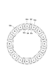
- the iron core 52a of the field core 52 is formed in a hollow cylindrical shape as illustrated in FIG.
- the iron core 52a includes eight N pole holes 52d having a circular cross section, eight S pole holes 52e having a circular cross section, and sixteen magnet housing holes 52f having a rectangular cross section.
- the N pole 52n is inserted into the N pole hole 52d.
- the S pole 52s is inserted into the S pole hole 52e.
- the permanent magnet 54 is embedded in the magnet housing hole 52f.
- the eight N pole holes 52d and the eight S pole holes 52e are alternately arranged with a predetermined distance in the circumferential direction.
- the N pole hole 52d and the S pole hole 52e are formed in parallel to the central axis of the iron core 52a.
- the N pole 52n accommodated in the N pole hole 52d and the S pole 52s accommodated in the S pole hole 52e extend in the axial direction on the outer peripheral side of the boss portion 17 and alternately in the circumferential direction.
- one magnet accommodation hole 52f is provided at a predetermined distance between the adjacent N pole hole 52d and S pole hole 52e.
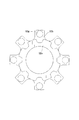
- the pair of N pole cores 52b are formed in a ring shape as illustrated in FIG. And the inner peripheral surface is fitted and fixed to the outer peripheral surface of the boss
- On the outer peripheral portion of each N pole core 52b eight concave portions that are recessed in the radial direction and eight convex portions that protrude in the radial direction are formed alternately in the circumferential direction.
- Each convex part is formed with a holding hole 52g for holding the end of the N pole 52n. Both ends of the N pole 52n are held in the holding holes 52g of the pair of N pole cores 52b in a state where the intermediate portion in the axial direction is fitted in the N pole hole 52d of the iron core 52a.
- the S pole core 52c is formed in a ring shape as illustrated in FIG.
- the inner diameter of the S pole core 52c is the same as the inner diameter of the N pole core 52b.
- the S pole core 52c is positioned between the pair of field windings 53 and is fitted and fixed to the outer peripheral surface of the central portion in the axial direction of the boss portion 17 (see FIG. 24).
- eight concave parts recessed in the radial direction and eight convex parts protruding in the radial direction are formed alternately in the circumferential direction.
- the protrusion front end surface (outer peripheral surface) of the convex part of S pole core 52c exists in the same position as the bottom face of the recessed part of N pole core 52b.
- the S pole core 52c is disposed in a state in which the protruding front end surface (outer peripheral surface) of the convex portion is in contact with the inner peripheral surface of the iron core 52a (see FIG. 24). Thereby, the S pole core 52c is magnetically connected to the S pole 52s accommodated in the S pole hole 52e via the iron core 52a.
- the outer diameter of the boss portion of the field core 52 is Db (hereinafter also referred to as “boss portion outer diameter Db”), and the rotor 50 (field core 32).
- the outer diameter of this is referred to as Dr (hereinafter also referred to as “rotor outer diameter Dr”).
- Dr hereinafter also referred to as “rotor outer diameter Dr”.
- the relationship between the boss part outer diameter Db and the rotor outer diameter Dr is set in a range where 0.46 ⁇ Db / Dr ⁇ 0.53. The relationship between the boss part outer diameter Db and the rotor outer diameter Dr will be described in detail later.
- the surface area of the outer peripheral surfaces of the N pole 52n and the S pole 52s serving as the magnetic pole portions is As (hereinafter also referred to as “magnetic pole surface area As”), and a pair of NS magnetic poles of the boss portion.
- the core cross-sectional area extending in the axial direction is referred to as Ab (hereinafter referred to as “boss section cross-sectional area Ab”).
- Ab The core cross-sectional area extending in the axial direction
- Ab the relationship between the magnetic pole part surface area As and the boss part cross-sectional area Ab is set in a range of 0.9 ⁇ As / Ab ⁇ 1.7.
- the boss section cross-sectional area Ab is represented by A / P, where A is the total cross-sectional area of the cylindrical boss section and P is the number of pole pairs of the rotating electrical machine.
- the permanent magnets 54 have a rectangular cross section and a rectangular outer shape, and are embedded one by one in the magnet accommodation holes 52f provided in the iron core 52a.
- the residual magnetic flux density Br of the permanent magnet 54 is 1 [T] or more.
- Each permanent magnet 54 is arranged with its easy axis oriented in the circumferential direction.
- Each permanent magnet 54 has a magnetic pole formed so as to coincide with the polarity alternately appearing at each magnetic pole portion (N pole 52n, S pole 52s) by the magnetomotive force of the field winding 53.
- the permanent magnet 54 is arranged in this way. Thereby, as illustrated in FIG. 30, two first and second magnet magnetic circuits 58 and 59 are formed in each permanent magnet 54.
- a first magnet magnetic circuit (indicated by a one-dot chain line in FIG. 30) 58 passes through the S pole hole 52e, the permanent magnet 54, and the N pole 52n of the iron core 52a and passes through the stator core 21 and out of the magnetic flux. It is a magnetic circuit through which magnetic flux flows so as to return to the S pole 52s.
- the second magnet magnetic circuit (indicated by a double line in FIG. 30) 59 passes through the S pole 52s, the permanent magnet 54, and the N pole 52n of the iron core 52a in the magnetic flux, and from the S pole core 52c to the boss portion.
- the magnetic circuit flows through the 17 and N pole cores 52 b so as to return to the S pole 52 s of the iron core 52 a, and the magnetic flux that is completed in the rotor 50 flows.
- the second magnet magnetic circuit 59 passing through the boss portion 17 is a magnetic circuit through which a magnet magnetic flux that is ineffective for the stator 20 flows.
- the first magnet magnetic circuit 58 is a magnetic circuit that is linked to the stator 20 and flows a magnetic flux that becomes counter electromotive force or torque.
- the field winding 53 generates a magnetomotive force in the boss portion 17 when the field current If is supplied from a field current control circuit (not shown).
- the N pole 52n is magnetized to the N pole
- the S pole 52s is magnetized to the S pole.
- the S pole 52 s and the S pole core 52 c of the iron core 52 a are passed from the boss portion 17 of the housing 10 through the pair of N pole core 52 b and N pole 52 n through the stator core 21.
- a d-axis magnetic circuit 56 (shown by a broken line in FIG. 31) through which a magnetic flux flows so as to return to the boss portion 17 is formed.
- the d-axis magnetic circuit 56 is a magnetic circuit that generates a counter electromotive force of the rotor 50.
- a current flows through the armature winding 25 by the magnetic flux interlinking with the stator 20 of the d-axis magnetic circuit 56 and the first magnet magnetic circuit 58.
- a q-axis magnetic circuit 57 (shown by a solid line in FIG. 31) is formed.
- the q-axis magnetic circuit 57 is a magnetic circuit formed by a magnetic flux passing through the q-axis at a position shifted by 90 ° in electrical angle from the d-axis of the stator core 21.
- the mode at the time of the load to the rotor 50 can be brought close to an IPM type rotor.
- the salient pole ratio ⁇ can be 2 or more.
- the method for measuring the permeance Prt of the d-axis magnetic circuit 56 and the permeance Pst of the q-axis magnetic circuit 57 is the same as in the first embodiment.
- the d-axis magnetic circuit 56 and the first magnet magnetic circuit 58 are magnetized from the S pole 52s to the N pole 52n via the iron core 52a, the stator 20, and the iron core 52a. Share the circuit.
- the d-axis magnetic circuit 56 and the second magnet magnetic circuit 59 return from the S pole 52s of the rotor 50 to the N pole 52n via the iron core 52a, the S pole core 52c, the boss portion 17, and the N pole core 52b.
- the magnetic circuit of the part up to is shared. Therefore, the d-axis magnetic circuit 56 and at least a part of the first and second magnet magnetic circuits 58 and 59 are shared.
- the cross-sectional area of the iron core extending in the axial direction per pair of NS magnetic poles of the boss portion 17 is Ab, and 5000 [A / m] of the boss portion 17 is 5000 [A / m].
- the magnetic flux density when the field is applied is B50.
- the residual magnetic flux density of the permanent magnet 54 disposed between the N pole 52n and the S pole 52s is Br, and the cross-sectional area of the surface serving as the magnetic pole of the permanent magnet 54 is Am.
- it is set so as to satisfy the relationship of 2 ⁇ Br [T] ⁇ Am [mm 2 ] ⁇ B50 [T] ⁇ Ab [mm 2 ].
- the part where the field core 52 and the d-axis magnetic circuit 56 of the housing 10 are formed is formed of two kinds of materials having different saturation magnetic flux densities Bs.
- the N pole 52n and the S pole 52s serving as the magnetic pole portions are formed of a material having a high saturation magnetic flux density Bs.
- portions of the field core 52 other than the N pole 52n and the S pole 52s and the boss portion 17 are formed of a material having a low saturation magnetic flux density Bs.
- the material with a high saturation magnetic flux density Bs and the material with a low saturation magnetic flux density Bs are the same as in the first embodiment.
- the cross-sectional area of the boss portion is Ab
- the magnetic flux density when the 5000 [A / m] field of the boss portion 17 is applied is B50.
- the residual magnetic flux density of the permanent magnet 54 is Br
- the cross-sectional area of the surface serving as the magnetic pole of the permanent magnet 54 is Am.
- the relationship of 2 ⁇ Br [T] ⁇ Am [mm 2 ] ⁇ B50 [T] ⁇ Ab [mm 2 ] is satisfied.
- back electromotive force can be lowered
- the relationship between the magnetic pole part surface area As and the boss part cross-sectional area Ab is set in a range where 0.9 ⁇ As / Ab ⁇ 1.7. That is, it means that the magnetic pole part surface area As is larger than the boss part cross-sectional area Ab.
- the permanent magnet 54 that has been conventionally used for the purpose of rectifying the magnetic flux between adjacent magnetic pole portions and preventing leakage is used like an IPM rotor in this embodiment. Thereby, not leakage prevention but magnetic flux can be increased. That is, it can function as a torque-up source or an output-up source.
- the relationship between the boss portion outer diameter Db and the rotor outer diameter Dr is set in a range of 0.46 ⁇ Db / Dr ⁇ 0.53.
- the boss section cross-sectional area Ab is a range determined in consideration of the reaction of the magnet magnetic force to the magnetic force of the boss portion to the maximum.
- the magnetic force of the boss part that can repel the reaction caused by the magnetic force of the magnet is acting on the field core 52.
- the base cross-sectional area At of the N pole 52n and the S pole 52s serving as the magnetic pole portions can transmit the total magnetic force of the boss portion and the total magnetic force of the magnet to the stator 20 side.
- the residual magnetic flux density Br of the permanent magnet 54 is 1 [T] or more.
- the magnet magnetic force is a bonded magnet of neodymium iron boron or a plastic molded magnet by injection molding of samarium iron nitrogen
- the demagnetizing field to the field core 52 cannot be sufficiently supplied in many cases. That is, in order to prepare the cross-sectional area of the magnet, the space of the field winding 53 is often reduced. Therefore, the above-described actions and effects are effectively exhibited particularly when the residual magnetic flux density Br of the permanent magnet 54 is 1 [T] or more.
- the field core 51 in which the d-axis magnetic circuit 56 is formed by the magnetomotive force of the field winding 55 is formed of two kinds of materials having different saturation magnetic flux densities Bs.
- the N pole 52n and the S pole 52s are made of a material having a high saturation magnetic flux density Bs, and the portions other than the N pole 52n and the S pole 52s are made of a material having a low saturation magnetic flux density Bs.
- the material with a low saturation magnetic flux density Bs used in parts other than the N pole 52n and the S pole 52s has a higher magnetic permeability than a material with a high saturation magnetic flux density Bs. Therefore, the effect of absorbing electromotive force is enhanced when the rotor 30 is not loaded.
- the rotating electrical machine according to the present embodiment will be described with reference to FIG.
- the rotating electrical machine according to this embodiment is a vehicle AC generator similar to that of the first embodiment.
- the rotating electrical machine according to the present embodiment is different from the first embodiment in the structure of the pole core constituting the field core.
- different points and important points will be described.
- symbol is used and detailed description is abbreviate
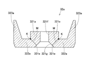
- the field core 32 includes a first pole core 32a and a second pole core 32b.
- the first pole core 32a includes a first boss portion 321a, a first disk portion 322a, and a first claw-shaped magnetic pole portion 323a.
- a groove portion 322c is formed in order to partially reduce the cross-sectional area perpendicular to the magnetic flux flow direction.
- the groove portion 322c is formed on the inner surface of the first disk portion 322a facing the second disk portion 322b in the axial direction.
- the groove portion 322c is formed in an arc shape so as to extend in the circumferential direction at a portion connected to the outermost first claw-shaped magnetic pole portion 323a in the radial direction of the first disk portion 322a.
- the first disk portion 322a is connected to the outermost first claw-shaped magnetic pole portion 323a in the radial direction, and extends in the circumferential direction on the inner surface facing the second disk portion 322b in the axial direction.
- an arcuate groove 322c is formed. Therefore, the area of the cross section orthogonal to the flow direction of the magnetic flux is partially reduced by the groove 322c. That is, the cross section of the outermost peripheral portion of the first disk portion 322a connected to the first claw-shaped magnetic pole portion 323a is reduced.
- the area A1 of a circle whose outer diameter Dr is the outer diameter of the first pole core 32a, which is the outer diameter of the rotor 30, and the cross-sectional area A2 of the portion where the area of the cross section perpendicular to the magnetic flux flow direction is minimized. are set in a range where 0.2116 ⁇ A2 / A1 ⁇ 0.2809.
- the cross-sectional area A2 is obtained by multiplying the cross-sectional area A0 of the first disk portion 322a at the portion where the groove portion 322c connected to the first claw-shaped magnetic pole portion 323a is formed by P times the number of pole pairs.
- the second pole core 32b has the same shape as the first pole core 32a. Therefore, a groove is formed in the second disk portion 322b in order to partially reduce the cross-sectional area perpendicular to the magnetic flux flow direction.
- the field core 32 has a partially reduced cross-sectional area perpendicular to the magnetic flux flow direction. Specifically, the area of the cross section of the disk portion is partially reduced. Therefore, the characteristics of the vehicle alternator change. That is, the vehicle alternator having different characteristics can be easily configured. Furthermore, in the present embodiment, the relationship between the area A1 of the circle having the outer diameter Dr of the rotor as the diameter and the cross-sectional area A2 of the portion where the cross-sectional area orthogonal to the magnetic flux flow direction is minimum is 0.2116. ⁇ A2 / A1 ⁇ 0.2809 is set.
- arc-shaped grooves are formed in the first disk portion 322a and the second disk portion 322b.
- the arc-shaped groove can be easily processed by a milling machine or the like. Therefore, the area of the cross section orthogonal to the flow direction of the magnetic flux can be easily reduced partially.
- the rotating electrical machine according to the present embodiment will be described with reference to FIG.
- the rotating electrical machine according to this embodiment is a vehicle AC generator similar to that of the first embodiment.
- the rotating electrical machine according to the present embodiment is different from the first embodiment in the structure of the pole core constituting the field core.
- the cross-sectional area of the disk portion is partially reduced.
- the rotating electrical machine according to this embodiment has a configuration in which the cross-sectional area of the disk portion is partially reduced by a configuration different from that of the third embodiment.
- different points and important points will be described.
- symbol is used and detailed description is abbreviate
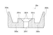
- the field core 32 includes a first pole core 32a and a second pole core 32b.
- the first pole core 32a includes a first boss portion 321a, a first disk portion 322a, and a first claw-shaped magnetic pole portion 323a.
- groove portions 322d and 322e having different widths are formed in order to partially reduce the cross-sectional area perpendicular to the flow direction of the magnetic flux.
- the groove portions 322d and 322e are formed on the inner surface of the first disk portion 322a facing the second disk portion 322b in the axial direction.
- the groove portions 322d and 322e are formed so as to extend radially outward from a predetermined position on the radially inner side of the first disk portion 322a.
- Grooves 322d and 322e are formed on the inner surface of the first disk portion 322a facing the second disk portion 322b in the axial direction so as to extend radially outward from a predetermined position on the radially inner side. ing. Therefore, the area of the cross section perpendicular to the flow direction of the magnetic flux is partially reduced by the grooves 322d and 322e. That is, the cross section of the outermost peripheral portion of the first disk portion 322a connected to the first claw-shaped magnetic pole portion 323a is reduced.
- the area A1 of the circle whose outer diameter Dr is the outer diameter of the first pole core 32a, which is the outer diameter of the rotor 30, and the area of the cross section perpendicular to the magnetic flux flow direction are the smallest.
- the relationship with the cross-sectional area A2 of the portion is set in a range where 0.2116 ⁇ A2 / A1 ⁇ 0.2809.
- the cross-sectional area A2 is obtained by multiplying the cross-sectional area A1 of the first disk portion 322a connected to the first claw-shaped magnetic pole portion 323a by the number P of pole pairs, as in the third embodiment.
- the second pole core 32b has the same shape as the first pole core 32a. Therefore, a groove is formed in the second disk portion 322b in order to partially reduce the cross-sectional area perpendicular to the magnetic flux flow direction.
- the field core 32 has a partially reduced cross-sectional area perpendicular to the magnetic flux flow direction. Specifically, the area of the cross section of the disk portion is partially reduced. Therefore, the characteristics of the vehicle alternator change. That is, the vehicle alternator having different characteristics can be easily configured. Furthermore, in the present embodiment, the relationship between the area A1 of the circle having the outer diameter Dr of the rotor as the diameter and the cross-sectional area A2 of the portion where the cross-sectional area orthogonal to the magnetic flux flow direction is minimum is 0.2116. ⁇ A2 / A1 ⁇ 0.2809 is set.
- the same relationship can be secured and the same effect can be obtained.
- the groove portions are formed in the first disk portion 322a and the second disk portion 322b so as to extend radially in the radial direction.
- ribs having a high moment of inertia in cross section are formed radially between the grooves. Therefore, in this embodiment, the rigidity of the field core 32 with respect to the centrifugal force can be improved as compared with the third embodiment.
- the formation of the grooves reduces the contact area between the first disk portion 322a and the field winding 33 and the contact area between the second disk portion 322b and the field winding 33.
- the field winding, the winding frame, and the like used before forming the groove can be used as they are. Therefore, in the case of configuring a vehicular AC generator having different characteristics, the cost associated with the change can be suppressed.
- a rotating electrical machine according to the present embodiment will be described with reference to FIG.
- the rotating electrical machine according to this embodiment is a vehicle AC generator similar to that of the first embodiment.
- the rotating electrical machine according to the present embodiment is different from the first embodiment in the structure of the pole core constituting the field core.
- the rotating electrical machine according to the present embodiment is obtained by partially reducing the cross-sectional area of the boss portion.
- symbol is used and detailed description is abbreviate
- the field core 32 includes a first pole core 32a and a second pole core 32b.
- the first pole core 32a includes a first boss portion 321a, a first disk portion 322a, and a first claw-shaped magnetic pole portion 323a.
- a groove portion 321c is formed in order to partially reduce the area of the cross section orthogonal to the flow direction of the magnetic flux.
- the groove portion 321c is formed in a circular shape on the outer peripheral surface of the intermediate portion in the axial direction of the first boss portion 321a.
- a circular groove portion 321c is formed on the outer peripheral surface of the intermediate portion in the axial direction of the first boss portion 321a. Therefore, the area of the cross section orthogonal to the flow direction of the magnetic flux is partially reduced by the groove 321c. That is, the cross section of the intermediate portion in the axial direction of the first boss portion 321a is partially smaller than the other portions.
- the area A1 of a circle whose outer diameter Dr is the outer diameter of the first pole core 32a, which is the outer diameter of the rotor 30, and the cross-sectional area A2 of the portion where the area of the cross section perpendicular to the magnetic flux flow direction is minimized. are set in a range where 0.2116 ⁇ A2 / A1 ⁇ 0.2809.
- the cross-sectional area A2 is a cross-sectional area of the first boss portion 321a in the portion where the groove portion 321c is formed. It is the area of the cross section orthogonal to the axial direction in the part in which the groove part 321c was formed.
- the second pole core 32b has the same shape as the first pole core 32a. Therefore, a groove is formed in the second boss portion 321b in order to partially reduce the area of the cross section perpendicular to the magnetic flux flow direction.
- the field core 32 has a partially reduced cross-sectional area perpendicular to the magnetic flux flow direction. Specifically, the cross-sectional area of the boss part is partially reduced. Therefore, the characteristics of the vehicle alternator change. That is, the vehicle alternator having different characteristics can be easily configured. Furthermore, in the present embodiment, the relationship between the area A1 of the circle having the outer diameter Dr of the rotor as the diameter and the cross-sectional area A2 of the portion where the cross-sectional area orthogonal to the magnetic flux flow direction is minimum is 0.2116. ⁇ A2 / A1 ⁇ 0.2809 is set.
- the same relationship can be secured and the same effect can be obtained.
- a groove is formed in the first boss 321a and the second boss 321b. Therefore, the field core 32 can be configured without reducing the rigidity against centrifugal force.
- the field winding, the winding frame, and the like used before forming the groove can be used as they are. Therefore, in the case of configuring a vehicular AC generator having different characteristics, the cost associated with the change can be suppressed.
- the rotating electrical machine according to this embodiment is a vehicle AC generator similar to that of the first embodiment.
- the rotating electrical machine according to the present embodiment is different from the first embodiment in the structure of the pole core constituting the field core.
- the cross-sectional area of the boss portion is partially reduced.
- a portion different from that of the fifth embodiment is partially reduced.
- the field core 32 includes a first pole core 32a and a second pole core 32b.
- the first pole core 32a includes a first boss portion 321a, a first disk portion 322a, and a first claw-shaped magnetic pole portion 323a.
- the first boss portion 321a is formed with a small-diameter portion 321d in order to partially reduce the cross-sectional area perpendicular to the magnetic flux flow direction.
- the small-diameter portion 321d is a portion having an outer diameter smaller than that of other portions, and is formed at the axial end portion of the first boss portion 321a facing the second boss portion 321b in the axial direction.
- a small-diameter portion 321d having a smaller outer diameter than other portions is formed at the axial end of the first boss portion 321a. Therefore, the area of the cross section orthogonal to the flow direction of the magnetic flux is partially reduced by the small diameter portion 321d. That is, the cross section of the end portion in the axial direction of the first boss portion 321a is partially smaller than other portions.
- the area A1 of a circle whose outer diameter Dr is the outer diameter of the first pole core 32a, which is the outer diameter of the rotor 30, and the cross-sectional area A2 of the portion where the area of the cross section perpendicular to the magnetic flux flow direction is minimized. are set in a range where 0.2116 ⁇ A2 / A1 ⁇ 0.2809.
- the cross-sectional area A2 is a cross-sectional area of the first boss portion 321a in the portion where the small diameter portion 321d is formed. It is an area of a cross section orthogonal to the axial direction in the portion where the small diameter portion 321d is formed.
- the second pole core 32b has the same shape as the first pole core 32a. Therefore, a small diameter portion is formed in the second boss portion 321b in order to partially reduce the area of the cross section perpendicular to the magnetic flux flow direction.
- the rotating electrical machine according to the present embodiment will be described with reference to FIG.
- the rotating electrical machine according to this embodiment is a vehicle AC generator similar to that of the first embodiment.
- the rotating electrical machine according to the present embodiment is different from the first embodiment in the structure of the pole core constituting the field core.
- the cross-sectional area of the boss portion is partially reduced.
- the rotating electrical machine according to the present embodiment has a configuration in which the cross-sectional area of the boss portion is partially reduced by a configuration different from the fifth and sixth embodiments.
- different points and important points will be described.
- symbol is used and detailed description is abbreviate
- the field core 32 includes a first pole core 32a and a second pole core 32b.
- the first pole core 32a includes a first boss portion 321a, a first disk portion 322a, and a first claw-shaped magnetic pole portion 323a.
- a chamfered portion 321e is formed on the first boss portion 321a in order to partially reduce the area of the cross section perpendicular to the flow direction of the magnetic flux.
- the first boss portion 321 a has a through-hole portion 321 f that fits with the rotation shaft 31.
- the chamfered portion 321e is formed over the entire circumference at the end portion in the axial direction of the through-hole portion 321f on the first disk portion 322a side.
- Magnetic flux flows in the axial direction through the first boss portion 321a. Further, the first disk portion 322a flows in the radial direction. In the portion of the first boss portion 321a connected to the first disk portion 322a on the first disk portion 322a side, the flow of magnetic flux changes from the axial direction to the radial direction, or from the radial direction to the axial direction.
- a chamfered portion 321e is formed over the entire circumference at the end portion in the axial direction of the through-hole portion 321f on the first disk portion 322a side. Therefore, the area of the cross section orthogonal to the flow direction of the magnetic flux is partially reduced by the groove 321c.
- the area A1 of a circle whose outer diameter Dr is the outer diameter of the first pole core 32a, which is the outer diameter of the rotor 30, and the cross-sectional area A2 of the portion where the area of the cross section perpendicular to the magnetic flux flow direction is minimized. are set in a range where 0.2116 ⁇ A2 / A1 ⁇ 0.2809.
- K is a point where the outer peripheral surface of the first boss 321a is in contact with the inner surface of the first disk 322a
- M is a line connecting the point K and the inclined surface 321g of the chamfered portion 321e with the shortest distance.
- the cross-sectional area A2 is the area of the cut surface cut along such a line M.
- the second pole core 32b has the same shape as the first pole core 32a. Therefore, a groove is formed in the second boss portion 321b in order to partially reduce the area of the cross section perpendicular to the magnetic flux flow direction.
- the field core 32 has a partially reduced cross-sectional area perpendicular to the magnetic flux flow direction. Specifically, the cross-sectional area of the boss part is partially reduced. Therefore, the characteristics of the vehicle alternator change. That is, the vehicle alternator having different characteristics can be easily configured. Furthermore, in the present embodiment, the relationship between the area A1 of the circle having the outer diameter Dr of the rotor as the diameter and the cross-sectional area A2 of the portion where the cross-sectional area orthogonal to the magnetic flux flow direction is minimum is 0.2116. ⁇ A2 / A1 ⁇ 0.2809 is set.
- the same relationship can be secured and the same effect can be obtained.
- chamfered portions are formed on the first boss portion 321a and the second boss portion 321b.
- the chamfered portion can be easily processed by a drill or the like. Therefore, the area of the cross section orthogonal to the flow direction of the magnetic flux can be easily reduced partially.
- the chamfered portions are only formed at the axial end portions of the through-hole portions of the first boss portion 321a and the second boss portion 321b, the field winding and the winding frame used before the chamfered portion formation can be removed. It can be used as it is. For this reason, in the present embodiment, when a vehicular AC generator having different characteristics is configured, the cost associated with the change can be suppressed.
- the rotating electrical machine according to the present embodiment will be described with reference to FIG.
- the rotating electrical machine according to this embodiment is a vehicle AC generator similar to that of the first embodiment.
- the rotating electrical machine according to the present embodiment is different from the first embodiment in the structure of the pole core constituting the field core.
- the rotating electrical machine according to the present embodiment has a reduced cross-sectional area of the boss portion.
- the rotating electrical machine according to the present embodiment is obtained by partially reducing a portion different from the seventh embodiment.
- different points and important points will be described.
- symbol is used and detailed description is abbreviate
- the field core 32 includes a first pole core 32a and a second pole core 32b.
- the first pole core 32a includes a first boss portion 321a, a first disk portion 322a, and a first claw-shaped magnetic pole portion 323a.
- the first boss portion 321a is formed with a chamfered portion 321h in order to partially reduce the cross-sectional area perpendicular to the direction of magnetic flux flow.
- the chamfered portion 321h is formed over the entire circumference at the end portion in the axial direction of the through-hole portion 321f on the second boss portion 321b side.
- a chamfered portion 321h is formed at an end portion in the axial direction of the through hole portion 321f on the second boss portion 321b side. Therefore, the chamfered portion 321h partially reduces the area of the cross section perpendicular to the magnetic flux flow direction. That is, the cross section of the end portion in the axial direction of the first boss portion 321a is partially smaller than other portions.
- the rotating electrical machine according to the present embodiment will be described with reference to FIG.
- the rotating electrical machine according to this embodiment is a vehicle AC generator similar to that of the first embodiment.
- the rotating electrical machine according to the present embodiment is different from the first embodiment in the structure of the pole core constituting the field core.
- the cross-sectional area of the boss portion is partially reduced.
- the rotating electrical machine according to the present embodiment has a configuration in which the cross-sectional area of the boss portion is partially reduced by a configuration different from the fifth to eighth embodiments.
- different points and important points will be described.
- symbol is used and detailed description is abbreviate
- the field core 32 includes a first pole core 32a and a second pole core 32b.
- the first pole core 32a includes a first boss portion 321a, a first disk portion 322a, and a first claw-shaped magnetic pole portion 323a.
- a groove portion 321i is formed in order to partially reduce the area of the cross section orthogonal to the flow direction of the magnetic flux.
- the groove part 321i is formed in a circular shape on the end face in the axial direction of the first boss part 321a facing the second boss part 321b in the axial direction.
- a circular groove 321i is formed on the axial end face of the first boss 321a. Therefore, the area of the cross section orthogonal to the flow direction of the magnetic flux is partially reduced by the groove 321i. That is, the cross section of the end portion in the axial direction of the first boss portion 321a is partially smaller than other portions.
- the area A1 of a circle whose outer diameter Dr is the outer diameter of the first pole core 32a, which is the outer diameter of the rotor 30, and the cross-sectional area A2 of the portion where the area of the cross section perpendicular to the magnetic flux flow direction is minimized. are set in a range where 0.2116 ⁇ A2 / A1 ⁇ 0.2809.
- the cross-sectional area A2 is a cross-sectional area of the end portion in the axial direction of the first boss portion 321a in which the groove portion 321i is formed. This is an area obtained by adding the areas of the end faces in the axial direction of the cylindrical portions 321j and 321k formed by providing the groove portion 321i.
- the second pole core 32b has the same shape as the first pole core 32a. Therefore, a groove is formed in the second boss portion 321b in order to partially reduce the area of the cross section perpendicular to the magnetic flux flow direction.
- the rotating electrical machine according to the present embodiment will be described with reference to FIG.
- the rotating electrical machine according to this embodiment is a vehicle AC generator similar to that of the first embodiment.
- the rotating electrical machine according to the present embodiment is different from the first embodiment in the structure of the pole core constituting the field core.
- the rotating electrical machine according to the present embodiment corresponds to a modification of the ninth embodiment.
- different points and important points will be described.
- symbol is used and detailed description is abbreviate
- grooves 321l and 321m are formed in the first boss portion 321a in order to partially reduce the cross-sectional area perpendicular to the magnetic flux flow direction.
- the groove portions 321l and 321m are formed concentrically on the axial end surface of the first boss portion 321a facing the second boss portion 321b in the axial direction. Therefore, the area of the cross section orthogonal to the flow direction of the magnetic flux is partially reduced by the grooves 321l and 321m. That is, the cross section of the end portion in the axial direction of the first boss portion 321a is partially smaller than other portions.
- the area A1 of a circle whose outer diameter Dr is the outer diameter of the first pole core 32a, which is the outer diameter of the rotor 30, and the cross-sectional area A2 of the portion where the area of the cross section perpendicular to the magnetic flux flow direction is minimized. are set in a range where 0.2116 ⁇ A2 / A1 ⁇ 0.2809.
- the cross-sectional area A2 is a cross-sectional area of the end portion in the axial direction of the first boss portion 321a in which the groove portions 321l and 321m are formed. This is an area obtained by adding the areas of the end surfaces in the axial direction of the cylindrical portions 321n to 321p formed by providing the groove portions 321l and 321m.
- the rotating electrical machine according to the present embodiment will be described with reference to FIG.
- the rotating electrical machine according to the present embodiment is a vehicle AC generator similar to that of the second embodiment.
- the rotating electrical machine according to the present embodiment is different from the second embodiment in the structure of the pole core constituting the field core.
- the field core of the third embodiment is modified so as to be compatible with a brushless structure.
- different points and important points will be described.
- symbol is used and detailed description is abbreviate
- omitted is used about the component corresponding to the field core of 3rd Embodiment.
- the field core 52 includes a first pole core 52h and a second pole core 52i.
- the first pole core 52h includes a first disk portion 522h and a first claw-shaped magnetic pole portion 523h.
- the first pole core 52h has a configuration in which the first boss portion 321a is removed from the first pole core 32a of the third embodiment.
- a groove portion 522j is formed in order to partially reduce the cross-sectional area perpendicular to the magnetic flux flow direction.
- the groove part 522j is formed on the inner surface of the first disk part 522h facing the second disk part 522i in the axial direction.
- the groove portion 522j is formed in an arc shape so as to extend in the circumferential direction at a portion connected to the outermost first claw-shaped magnetic pole portion 523h in the radial direction of the first disk portion 522h.
- the second pole core 52i includes a second boss part 521i, a second disk part 522i, and a second claw-shaped magnetic pole part 523i.
- the second pole core 52i has the same configuration as the first pole core 32a of the third embodiment.
- a groove portion 522k is formed in order to partially reduce the cross-sectional area perpendicular to the magnetic flux flow direction.
- the groove portion 522k is formed on the inner surface of the second disk portion 522i that faces the first disk portion 522h in the axial direction.
- the groove portion 522k is formed in an arc shape so as to extend in the circumferential direction at a portion connected to the outermost second claw-shaped magnetic pole portion 523i in the radial direction of the second disk portion 522i.
- the first pole core 52h is arranged such that the inner peripheral surface of the first disk portion 522h is opposed to the outer peripheral surface of the boss portion 17 in the radial direction.
- the second pole core 52i is disposed such that the axial end surface of the second boss portion 521i is opposed to the axial end surface of the boss portion 17 in the axial direction.
- the second pole core 52i is arranged such that the first claw-shaped magnetic pole portions 523h and the second claw-shaped magnetic pole portions 523i are alternately arranged in the circumferential direction.
- a permanent magnet 54 is disposed between the first claw-shaped magnetic pole part 523h and the second claw-shaped magnetic pole part 523i adjacent to each other in the circumferential direction.
- the permanent magnet 54 is arranged with the easy magnetization axis oriented in the circumferential direction.
- the permanent magnet 54 has magnetic poles formed by the magnetomotive force of the field winding 53 so as to coincide with the polarities alternately appearing in the first claw-shaped magnetic pole portion 523h and the second claw-shaped magnetic pole portion 523i.
- the inner peripheral sides of the first claw-shaped magnetic pole part 523h and the second claw-shaped magnetic pole part 523i are fixed by a fixing member 52l.
- the first pole core 52h and the second pole core 52i fixed by the fixing member 52l are rotatably supported by the housing 10 via bearings.
- a field winding 53 is arranged in the space between the first pole core 52h and the second pole core 52i.
- the field winding 53 is fixed to the boss portion 17.
- Arc-shaped groove portions 522j and 522k are formed so as to extend in the circumferential direction at the portions connected to the outermost claw-shaped magnetic pole portions 523h and 523i in the radial direction of the disk portions 522h and 522i. Therefore, the area of the cross section orthogonal to the flow direction of the magnetic flux is partially reduced by the grooves 522j and 522k. That is, the cross section of the outermost peripheral portion of the disk portions 522h and 522i connected to the claw-shaped magnetic pole portions 523h and 523i is reduced.
- the area A1 of a circle having the outer diameter Dr of the pole cores 52h, 52i as the outer diameter of the rotor 50 as the diameter, and the cross-sectional area A2 of the portion where the area of the cross section perpendicular to the magnetic flux flow direction is minimized. are set in a range where 0.2116 ⁇ A2 / A1 ⁇ 0.2809.
- the cross-sectional area A2 is obtained by multiplying the cross-sectional area A0 of the disk portions 522h and 522i in the portion where the groove portions 522j and 522k are formed connected to the claw-shaped magnetic pole portions 523h and 523i by P times the number of pole pairs.
- the basic configuration of the field core is the same as in the fourth to tenth embodiments. Therefore, the configurations of the fourth to tenth embodiments can be applied to a vehicular AC generator with a brushless structure. In this case, even with the brushless structure, the same effect as in the fourth to tenth embodiments can be obtained.
- the d-axis magnetic circuits 36 and 56 and a part of the first and second magnet magnetic circuits 38, 39, 58, and 59 are shared.
- the permanent magnets 34 and 54 are embedded on the d-axis magnetic circuits 36 and 56, the d-axis magnetic circuit and all of the first and second magnet magnetic circuits are shared. It may be.
- a cylindrical permanent magnet 34A having magnetic poles at both ends in the axial direction on the outer periphery of the boss 321 of the field core 32 where the d-axis magnetic circuit 36 is formed. Are mounted coaxially. In this way, the d-axis magnetic circuit 36 (see FIG.
- the total radial cross-sectional area of the portion where the permanent magnet 34A of the boss portion 321 is mounted is A, and the number of pole pairs of the rotating electrical machine is P.
- the core cross-sectional area Ab extending in the axial direction per pair of NS magnetic poles of the boss portion 321 is represented by A / P.
- the cross-sectional area of the disk portions 322a and 322b is the cross-sectional area of the portion (disk portion iron core portion) where the permanent magnets of the disk portions 322a and 322b are provided.
- the present invention is not limited thereto.
- the technology of the present disclosure can be applied to an electric motor as a rotating electric machine mounted on a vehicle, and further to a rotating electric machine that can selectively use a generator and an electric motor.
- a first rotating electrical machine that is an aspect of the technology of the present disclosure includes an annular stator (20) in which an armature winding (25) is wound around a stator core (21), and a radial direction on the inner peripheral side of the stator. And a rotor (30) disposed opposite to each other.
- the rotor has a cylindrical boss portion (321, 321a, 321b) and a plurality of claw-shaped magnetic pole portions (323, 323a) which are arranged on the outer peripheral side of the boss portion and have magnetic poles having different polarities alternately in the circumferential direction. , 323b), a field winding (33) wound around the outer periphery of the boss and generating a magnetomotive force when energized, and a claw-shaped magnetic pole adjacent in the circumferential direction.
- the permanent magnets (34, 34A) are arranged such that the easy magnetization axis is oriented in the circumferential direction and the magnetic poles are formed so as to coincide with the polarities alternately appearing in the claw-shaped magnetic pole portions by the magnetomotive force of the field winding. And comprising.
- the magnetic flux formed by the magnetomotive force of the field windings flows through the boss portion, the pair of claw-shaped magnetic pole portions, and the stator core, and the permanent magnet At least a part of the magnet magnetic circuit (38, 39) through which the magnetic flux formed by the magnetic force flows is shared.
- the q-axis is formed by the permeance Prt of the d-axis magnetic circuit and the current flowing through the armature winding and shifted by 90 ° in electrical angle from the d-axis.
- the relationship with the permeance Pst of the q-axis magnetic circuit (37) passing through is set such that Pst> Prt.
- the permanent magnet disposed between the claw-shaped magnetic pole portions adjacent in the circumferential direction causes the magnetic magnetic circuit in which the magnetic flux linked to the stator flows, and the rotor through the boss portion.
- Two magnet magnetic circuits are formed, a magnet magnetic circuit in which the flow of magnetic flux is completed.
- the magnet magnetic flux that flows through the magnet magnetic circuit that passes through the boss portion and is completed in the rotor flows in the opposite direction to the magnetic flux of the d-axis magnetic circuit. For this reason, the resistance becomes large and difficult to flow. Therefore, in the first rotating electrical machine, the relationship between the permeance Prt of the d-axis magnetic circuit and the permeance Pst of the q-axis magnetic circuit is set to satisfy Pst> Prt. Therefore, among the two magnet magnetic circuits, the magnet magnetic flux of the magnet magnetic circuit through which the magnetic flux interlinking with the stator flows can be increased. As a result, the magnetic flux can be effectively used to greatly improve the power generation capacity.
- a second rotating electric machine having a brushless structure which is an aspect of the technology of the present disclosure, includes an annular stator (20) in which an armature winding (25) is wound around a stator core (21), and an inner portion of the stator.
- the rotor (50) arrange
- the housing has a boss portion (17) that is disposed on the inner peripheral side of the rotor and in which a field winding (53) that generates a magnetomotive force when energized is wound on the outer peripheral side.
- the rotor is adjacent to the field core (52) having a plurality of magnetic pole portions (52n, 52s) disposed on the outer peripheral side of the field winding and having magnetic poles having different polarities alternately in the circumferential direction.
- the permanent magnet (54) is arranged such that the easy axis of magnetization is arranged in the circumferential direction between the magnetic pole portions to be aligned, and the magnetic poles are formed so as to coincide with the polarities alternately appearing in the magnetic pole portions by the magnetomotive force of the field winding. And).
- the magnetic flux formed by the magnetomotive force of the field winding is generated by the d-axis magnetic circuit (56) flowing via the boss portion, the pair of magnetic pole portions, and the stator core, and the magnetic force of the permanent magnet. At least a part of the formed magnetic circuit (58, 59) is shared.
- the q-axis is formed by the permeance Prt of the d-axis magnetic circuit and the current flowing through the armature winding and is shifted by 90 ° in electrical angle from the d-axis.
- the relationship with the permeance Pst of the q-axis magnetic circuit (57) passing through is set such that Pst> Prt.
- the permanent magnet disposed between the magnetic pole portions adjacent in the circumferential direction passes through the boss portion and the magnet magnetic circuit through which the magnetic flux interlinked with the stator flows.
- Two magnet magnetic circuits that is, a magnet magnetic circuit that completes the flow of magnetic flux, are formed.
- the magnet magnetic flux that flows through the magnet magnetic circuit that passes through the boss portion and is completed in the rotor flows in the opposite direction to the magnetic flux of the d-axis magnetic circuit. For this reason, the resistance becomes large and difficult to flow. Therefore, in the second rotating electrical machine, the relationship between the permeance Prt of the d-axis magnetic circuit and the permeance Pst of the q-axis magnetic circuit is set to satisfy Pst> Prt. Therefore, the magnet magnetic flux of the magnet magnetic circuit through which the magnetic flux linked to the stator flows out of the two magnet magnetic circuits increases. As a result, the magnetic flux can be effectively used to greatly improve the power generation capacity.
- brushless rotating electrical machines do not need to be restricted by brush current. Therefore, the current value of the field current If restricted by the brush can be increased. As a result, even in a brushless rotating electric machine, the field circuit can be saturated and the magnet magnetic force can be used effectively. Moreover, the electric circuit which supplies a field current to the field winding is independent. Therefore, in the centrifugal strength, which is a weak point of the Landell rotor with magnet, it is not necessary to receive the centrifugal force of the electric circuit behind the magnetic pole portion. Thereby, the stress by centrifugal force can be reduced.
- the cross-sectional area of the iron core extending in the axial direction around a pair of NS magnetic poles of the boss portion is Ab
- the magnetic flux density when a field of 5000 [A / m] is applied to the boss portion is B50.
- the residual magnetic flux density of the permanent magnets disposed between the claw-shaped magnetic pole portions and between the magnetic pole portions is Br
- the cross-sectional area of the surface that becomes the magnetic pole of the permanent magnet is Am.
- the first or second rotating electrical machine is configured to satisfy the relationship of 2 ⁇ Br ⁇ Am ⁇ B50 ⁇ Ab. According to this configuration, in the rotating electrical machine of the present disclosure, the magnetic force generated by the permanent magnet can be absorbed by the d-axis magnetic circuit. Therefore, the counter electromotive force can be lowered, and the generated power in the high-speed rotation state when no current is supplied can be suppressed.
- Prt 2n (n is a real number of 1 or more): 1.
- the salient pole ratio ⁇ which is the ratio (Lq / Ld) between the q-axis inductance Lq and the d-axis inductance Ld, can be made 2 or more.
- a third rotating electric machine that is an aspect of the technology of the present disclosure includes an annular stator (20) in which an armature winding (25) is wound around a stator core (21), and an inner peripheral side of the stator. And a rotor (30) arranged to be rotatable in the radial direction.
- the rotor has a cylindrical boss portion (321, 321a, 321b) and a plurality of claw-shaped magnetic pole portions (323, 323a) which are arranged on the outer peripheral side of the boss portion and have magnetic poles having different polarities alternately in the circumferential direction. , 323b), a field winding (33) wound around the outer periphery of the boss and generating a magnetomotive force when energized, and a claw-shaped magnetic pole adjacent in the circumferential direction. And a permanent magnet (34) in which a magnetic pole is formed so as to coincide with the polarity alternately appearing in the claw-shaped magnetic pole portion by the magnetomotive force of the field winding. .
- the surface area of the outer peripheral surface of the claw-shaped magnetic pole portion is As
- the cross-sectional area of the iron core extending in the axial direction per pair of NS magnetic poles of the boss portion is Ab.
- the relationship between the surface area As and the cross-sectional area Ab is set in a range where 0.9 ⁇ As / Ab ⁇ 1.7.
- the relationship between the surface area As of the outer peripheral surface of the claw-shaped magnetic pole part and the core cross-sectional area Ab extending in the axial direction per pair of NS magnetic poles of the boss part is 0.
- the range is set to 9 ⁇ As / Ab ⁇ 1.7. Therefore, among the magnetic circuit formed by the permanent magnets arranged between the claw-shaped magnetic pole portions adjacent in the circumferential direction, the magnetic flux of the magnetic magnetic circuit through which the magnetic flux linked to the stator flows can be increased. As a result, the magnetic flux can be effectively used to greatly improve the power generation capacity.
- claw-shaped magnetic pole part was conventionally used for the purpose of the rectification
- the permanent magnet disposed between the claw-shaped magnetic pole portions is used like the permanent magnet of the IPM rotor. Thereby, not leakage prevention etc. but magnetic flux can be increased. That is, it can function as a torque-up source or an output-up source.
- a fourth rotating electric machine having a brushless structure that is an aspect of the technology of the present disclosure includes an annular stator (20) in which an armature winding (25) is wound around a stator core (21), and an inner portion of the stator.
- the housing is disposed on the inner peripheral side of the rotor and has a boss portion (17) around which a field winding (53) that generates a magnetomotive force when energized is wound on the outer peripheral side.
- the rotor is adjacent to the field core (52) having a plurality of magnetic pole portions (523h, 523i) disposed on the outer peripheral side of the field winding and having magnetic poles having different polarities alternately in the circumferential direction.
- the permanent magnet (54) is arranged such that the easy axis of magnetization is arranged in the circumferential direction between the magnetic pole portions to be aligned, and the magnetic poles are formed so as to coincide with the polarities alternately appearing in the magnetic pole portions by the magnetomotive force of the field winding. And).
- the surface area of the outer peripheral surface of the magnetic pole part is As
- the cross-sectional area of the iron core extending in the axial direction per pair of NS magnetic poles of the boss part is Ab.
- the relationship between the surface area As and the cross-sectional area Ab is set in a range where 0.9 ⁇ As / Ab ⁇ 1.7.
- the relationship between the surface area As of the outer peripheral surface of the magnetic pole portion and the core cross-sectional area Ab extending in the axial direction per pair of NS magnetic poles of the boss portion is 0.9 ⁇
- the range is set to As / Ab ⁇ 1.7. Therefore, the magnet magnetic flux of the magnet magnetic circuit through which the magnetic magnetic flux linked to the stator flows among the magnetic magnetic circuits formed by the permanent magnets arranged between the magnetic pole portions adjacent in the circumferential direction can be increased. As a result, the magnetic flux can be effectively used to greatly improve the power generation capacity.
- positioned between magnetic pole parts was conventionally used for the purpose of the rectification
- the permanent magnet disposed between the magnetic pole portions is used like the permanent magnet of the IPM rotor.
- magnetic flux can be increased. That is, it can function as a torque-up source or an output-up source.
- the relationship between the outer diameter Db of the boss portion and the outer diameter Dr of the rotor is set in a range where 0.46 ⁇ Db / Dr ⁇ 0.53.
- the cross-sectional area of the boss portion is in a range determined in consideration of the reaction of the magnet magnetic force to the magnetic force of the boss portion to the maximum. It is assumed that the magnetic force of the boss part that can repel the reaction caused by the magnetic force of the magnet is acting on the field core. At this time, the base cross-sectional area of the claw-shaped magnetic pole portion can transmit the total magnetic force of the boss portion and the total magnetic force of the permanent magnet to the stator side.
- the residual magnetic flux density Br of the permanent magnet is 1 [T] or more. According to this configuration, in the rotating electrical machine of the present disclosure, the above-described functions and effects can be more effectively exhibited.
- the portion where the d-axis magnetic circuit (36, 56) is formed is formed of two types of materials having different saturation magnetic flux densities Bs.
- the claw-shaped magnetic pole part or the magnetic pole part is formed of a material having a high saturation magnetic flux density Bs
- the portion other than the claw-shaped magnetic pole part or the magnetic pole part is formed of a material having a low saturation magnetic flux density Bs.
- a material having a low saturation magnetic flux density Bs has a higher magnetic permeability than a material having a high saturation magnetic flux density Bs. According to this configuration, in the rotating electrical machine of the present disclosure, the ability to absorb electromotive force is enhanced when there is no load on the rotor.
- the field core has a partially reduced cross-sectional area perpendicular to the magnetic flux flow direction.
- the relationship between the area A1 of the circle whose diameter is the outer diameter Dr of the rotor and the cross-sectional area A2 of the portion where the area of the cross section perpendicular to the flow direction of the magnetic flux is minimum is The range is set to 0.2116 ⁇ A2 / A1 ⁇ 0.2809. According to this configuration, in the rotating electrical machine of the present disclosure, the field core has a partially reduced cross-sectional area perpendicular to the flow direction of the magnetic flux. Therefore, the characteristics of the rotating electrical machine change. That is, a rotating electrical machine having different characteristics can be easily configured.
- the relationship between the area A1 of the circle having the outer diameter Dr of the rotor as the diameter and the cross-sectional area A2 of the portion where the cross-sectional area orthogonal to the magnetic flux flow direction is minimum is 0. .2116 ⁇ A2 / A1 ⁇ 0.2809 is set.
- the same magnetic relationship can be secured as in the case where the relationship between the outer diameter Db of the boss portion and the outer diameter Dr of the rotor is set in a range where 0.46 ⁇ Db / Dr ⁇ 0.53. The same effect can be obtained.
- first magnet magnetic circuit 39 ... second magnet magnetic circuit, 50 ... Rotor, 52 ... field core, 52n ... N pole (magnetic pole), 52s ... S pole (magnetic pole), 53 ... field winding, 54 ... permanent magnet, 56 ... d-axis magnetic circuit, 57 ... q-axis magnetism Circuit, 58 ... 1 magnet magnetic circuit, 59 ... second magnet magnetic circuit.
Landscapes
- Engineering & Computer Science (AREA)
- Power Engineering (AREA)
- Iron Core Of Rotating Electric Machines (AREA)
- Synchronous Machinery (AREA)
Abstract
La présente invention concerne un générateur de courant alternatif de véhicule (1) qui comprend : un stator (20) pourvu d'un enroulement d'induit (25) enroulé autour d'un noyau de stator (21) ; un rotor (30) disposé dans le stator (20) dans la direction radiale. Le rotor (30) comprend : un noyau de champ (32) pourvu d'une section de bossage (321) et d'une pluralité de sections de pôles magnétiques en forme de crochet (323) ayant des pôles magnétiques de polarités alternées, formés dans la direction circonférentielle ; un enroulement de champ enroulé sur le côté périphérique externe de la section de bossage (321) ; des aimants permanents (34) disposés respectivement entre des sections adjacentes de pôles magnétiques en forme de crochet (323) dans la direction périphérique. Un circuit magnétique d'axe d (36), formé par la force magnétomotrice de l'enroulement de champ (33), et au moins une partie des premier et second circuits magnétiques d'aimant (38, 39), formés par la force magnétique des aimants permanents (34), sont partagés. Lorsque le rotor (30) est sous charge, la relation entre la perméance (Prt) du circuit magnétique d'axe d (36) et la perméance (Pst) d'un circuit magnétique d'axe q (37) est établie de sorte que Pst > Prt.
Priority Applications (3)
| Application Number | Priority Date | Filing Date | Title |
|---|---|---|---|
| CN201780034361.XA CN109314415B (zh) | 2016-06-03 | 2017-06-01 | 旋转电机 |
| US16/306,767 US10958117B2 (en) | 2016-06-03 | 2017-06-01 | Rotary electrical machine |
| DE112017002812.4T DE112017002812T5 (de) | 2016-06-03 | 2017-06-01 | Rotierende elektrische Maschine |
Applications Claiming Priority (4)
| Application Number | Priority Date | Filing Date | Title |
|---|---|---|---|
| JP2016112286 | 2016-06-03 | ||
| JP2016-112286 | 2016-06-03 | ||
| JP2017089380A JP6579395B2 (ja) | 2016-06-03 | 2017-04-28 | 回転電機 |
| JP2017-089380 | 2017-04-28 |
Publications (1)
| Publication Number | Publication Date |
|---|---|
| WO2017209245A1 true WO2017209245A1 (fr) | 2017-12-07 |
Family
ID=60478544
Family Applications (1)
| Application Number | Title | Priority Date | Filing Date |
|---|---|---|---|
| PCT/JP2017/020444 Ceased WO2017209245A1 (fr) | 2016-06-03 | 2017-06-01 | Machine électrique tournante |
Country Status (1)
| Country | Link |
|---|---|
| WO (1) | WO2017209245A1 (fr) |
Cited By (1)
| Publication number | Priority date | Publication date | Assignee | Title |
|---|---|---|---|---|
| CN113412570A (zh) * | 2019-02-05 | 2021-09-17 | 株式会社电装 | 旋转电机 |
Citations (4)
| Publication number | Priority date | Publication date | Assignee | Title |
|---|---|---|---|---|
| JP2000050588A (ja) * | 1998-07-29 | 2000-02-18 | Denso Corp | 車両用交流発電機 |
| US6885129B1 (en) * | 2000-09-26 | 2005-04-26 | Mitsubishi Denki Kabushiki Kaisha | Ac generator for vehicle |
| JP2006060922A (ja) * | 2004-08-20 | 2006-03-02 | Hitachi Ltd | 車両用電源装置 |
| JP2009207333A (ja) * | 2008-02-29 | 2009-09-10 | Denso Corp | ランデル型ロータ型モータ |
-
2017
- 2017-06-01 WO PCT/JP2017/020444 patent/WO2017209245A1/fr not_active Ceased
Patent Citations (4)
| Publication number | Priority date | Publication date | Assignee | Title |
|---|---|---|---|---|
| JP2000050588A (ja) * | 1998-07-29 | 2000-02-18 | Denso Corp | 車両用交流発電機 |
| US6885129B1 (en) * | 2000-09-26 | 2005-04-26 | Mitsubishi Denki Kabushiki Kaisha | Ac generator for vehicle |
| JP2006060922A (ja) * | 2004-08-20 | 2006-03-02 | Hitachi Ltd | 車両用電源装置 |
| JP2009207333A (ja) * | 2008-02-29 | 2009-09-10 | Denso Corp | ランデル型ロータ型モータ |
Cited By (1)
| Publication number | Priority date | Publication date | Assignee | Title |
|---|---|---|---|---|
| CN113412570A (zh) * | 2019-02-05 | 2021-09-17 | 株式会社电装 | 旋转电机 |
Similar Documents
| Publication | Publication Date | Title |
|---|---|---|
| JP6579395B2 (ja) | 回転電機 | |
| CN109219915B (zh) | 旋转电机 | |
| JP6589931B2 (ja) | 回転電機駆動システム | |
| US7420314B2 (en) | Alternating-current dynamoelectric machine | |
| JP2019122229A (ja) | 回転電機 | |
| JP2004350427A (ja) | 回転電機とその回転子 | |
| US20150091403A1 (en) | Transverse flux machine and vehicle | |
| US10910932B2 (en) | Rotating electric machine | |
| JPWO2011121770A1 (ja) | 車両用交流発電機 | |
| EP1202431B1 (fr) | Rotor d'un générateur à courant alternatif à champ rotatif | |
| JP6766575B2 (ja) | 回転電機 | |
| JP6592525B2 (ja) | 磁石式回転子、磁石式回転子を備える回転電機及び回転電機を備える電気自動車 | |
| JP6766574B2 (ja) | 回転電機 | |
| US10848041B2 (en) | Rotating electric machine | |
| WO2019131911A1 (fr) | Machine électrique rotative | |
| JP2019122228A (ja) | 回転電機 | |
| WO2017209245A1 (fr) | Machine électrique tournante | |
| JP2002191157A (ja) | 永久磁石併用同期回転機 | |
| JP4066219B2 (ja) | 静止界磁コイル式磁石併用同期機 | |
| CN110391701B (zh) | 旋转电机 | |
| WO2017209248A1 (fr) | Système d'entraînement de machine électrique tournante | |
| WO2017209246A1 (fr) | Machine électrique tournante | |
| JP2002191196A (ja) | 車両用交流発電装置 | |
| JP2017220986A (ja) | 回転電機の回転子 | |
| JP2009254020A (ja) | 回転電機 |
Legal Events
| Date | Code | Title | Description |
|---|---|---|---|
| 121 | Ep: the epo has been informed by wipo that ep was designated in this application |
Ref document number: 17806795 Country of ref document: EP Kind code of ref document: A1 |
|
| 122 | Ep: pct application non-entry in european phase |
Ref document number: 17806795 Country of ref document: EP Kind code of ref document: A1 |