WO2017209273A1 - 生体磁気測定装置 - Google Patents
生体磁気測定装置 Download PDFInfo
- Publication number
- WO2017209273A1 WO2017209273A1 PCT/JP2017/020574 JP2017020574W WO2017209273A1 WO 2017209273 A1 WO2017209273 A1 WO 2017209273A1 JP 2017020574 W JP2017020574 W JP 2017020574W WO 2017209273 A1 WO2017209273 A1 WO 2017209273A1
- Authority
- WO
- WIPO (PCT)
- Prior art keywords
- magnetic sensor
- sensor
- magnetic
- biomagnetism measuring
- biomagnetism
- Prior art date
- Legal status (The legal status is an assumption and is not a legal conclusion. Google has not performed a legal analysis and makes no representation as to the accuracy of the status listed.)
- Ceased
Links
Images






Classifications
-
- A—HUMAN NECESSITIES
- A61—MEDICAL OR VETERINARY SCIENCE; HYGIENE
- A61B—DIAGNOSIS; SURGERY; IDENTIFICATION
- A61B5/00—Measuring for diagnostic purposes; Identification of persons
- A61B5/05—Detecting, measuring or recording for diagnosis by means of electric currents or magnetic fields; Measuring using microwaves or radio waves
-
- G—PHYSICS
- G01—MEASURING; TESTING
- G01R—MEASURING ELECTRIC VARIABLES; MEASURING MAGNETIC VARIABLES
- G01R33/00—Arrangements or instruments for measuring magnetic variables
-
- G—PHYSICS
- G01—MEASURING; TESTING
- G01R—MEASURING ELECTRIC VARIABLES; MEASURING MAGNETIC VARIABLES
- G01R33/00—Arrangements or instruments for measuring magnetic variables
- G01R33/0094—Sensor arrays
-
- A—HUMAN NECESSITIES
- A61—MEDICAL OR VETERINARY SCIENCE; HYGIENE
- A61B—DIAGNOSIS; SURGERY; IDENTIFICATION
- A61B2562/00—Details of sensors; Constructional details of sensor housings or probes; Accessories for sensors
- A61B2562/02—Details of sensors specially adapted for in-vivo measurements
- A61B2562/0223—Magnetic field sensors
-
- A—HUMAN NECESSITIES
- A61—MEDICAL OR VETERINARY SCIENCE; HYGIENE
- A61B—DIAGNOSIS; SURGERY; IDENTIFICATION
- A61B2562/00—Details of sensors; Constructional details of sensor housings or probes; Accessories for sensors
- A61B2562/04—Arrangements of multiple sensors of the same type
- A61B2562/046—Arrangements of multiple sensors of the same type in a matrix array
-
- A—HUMAN NECESSITIES
- A61—MEDICAL OR VETERINARY SCIENCE; HYGIENE
- A61B—DIAGNOSIS; SURGERY; IDENTIFICATION
- A61B2562/00—Details of sensors; Constructional details of sensor housings or probes; Accessories for sensors
- A61B2562/16—Details of sensor housings or probes; Details of structural supports for sensors
-
- A—HUMAN NECESSITIES
- A61—MEDICAL OR VETERINARY SCIENCE; HYGIENE
- A61B—DIAGNOSIS; SURGERY; IDENTIFICATION
- A61B2576/00—Medical imaging apparatus involving image processing or analysis
- A61B2576/02—Medical imaging apparatus involving image processing or analysis specially adapted for a particular organ or body part
- A61B2576/023—Medical imaging apparatus involving image processing or analysis specially adapted for a particular organ or body part for the heart
-
- A—HUMAN NECESSITIES
- A61—MEDICAL OR VETERINARY SCIENCE; HYGIENE
- A61B—DIAGNOSIS; SURGERY; IDENTIFICATION
- A61B2576/00—Medical imaging apparatus involving image processing or analysis
- A61B2576/02—Medical imaging apparatus involving image processing or analysis specially adapted for a particular organ or body part
- A61B2576/026—Medical imaging apparatus involving image processing or analysis specially adapted for a particular organ or body part for the brain
-
- A—HUMAN NECESSITIES
- A61—MEDICAL OR VETERINARY SCIENCE; HYGIENE
- A61B—DIAGNOSIS; SURGERY; IDENTIFICATION
- A61B5/00—Measuring for diagnostic purposes; Identification of persons
- A61B5/40—Detecting, measuring or recording for evaluating the nervous system
- A61B5/4058—Detecting, measuring or recording for evaluating the nervous system for evaluating the central nervous system
- A61B5/4064—Evaluating the brain
Definitions
- the present invention relates to a biomagnetism measuring apparatus using a magnetic sensor.
- an MR sensor using a magnetoresistive effect element is known.
- the direct current resistance applied to the MR element changes according to the strength of the magnetic field.
- the MR sensor detects a change in the magnetic field and the presence or absence of a magnetic substance as a change in voltage.
- MR sensors are widely used as magnetic heads of hard disk devices, rotation sensors (encoders), and position sensors.
- mobile devices such as smartphones and tablet devices have become widespread, and mobile devices have built-in azimuth sensors using MR sensors that measure azimuth using geomagnetism.
- Information obtained from the azimuth sensor is used for navigation or the like using position information by GPS (Global Positioning System).
- biomagnetism measuring devices such as a magnetoencephalograph, a magnetocardiograph, and a magnetomagnetometer that detect weak low-frequency magnetism generated in association with the electrical activity of the brain, heart, and muscle of a living body are used in the medical field.
- the magnetoencephalogram generated by the electrical activity of the brain is about one hundred millionth the intensity of the geomagnetism
- the magnetocardiogram generated by the electrical activity of the heart's myocardium is one millionth of the geomagnetism.
- the size is about one. Therefore, when detecting magnetism generated by a living body (hereinafter also referred to as “biomagnetism”), the magnetic sensor is required to have extremely high detection performance.
- a superconducting quantum interference element (Superducting Quantum Interference Device, hereinafter also referred to as “SQUID”) is known (for example, see Patent Document 1).
- the SQUID sensor is a magnetic sensor using a superconducting phenomenon, and has a Josephson junction. Therefore, when using the SQUID sensor, cooling with a refrigerant such as liquid helium or liquid nitrogen is required. Therefore, the SQUID sensor must be provided in a dewar that stores the refrigerant, and it is difficult to bring the SQUID sensor into close contact with the living body when detecting biomagnetism.
- a plurality of SQUID sensors are arranged in an array in the dewar.
- the SQUID sensor when the SQUID sensor is disposed, the SQUID sensor must be disposed so as not to electromagnetically affect the Josephson junction inside the SQUID. For this reason, it is not easy to change, replace, and take out the SQUID sensor.
- the SQUID sensor is an ultra-sensitive magnetic sensor, there are problems such as being unable to be sufficiently close to the living body and being difficult to handle.
- Patent Document 2 proposes a biomagnetism measuring apparatus in which a covering member that shields a living body from an external magnetic field is formed in a helmet shape or a cylindrical shape, and an MR sensor is lined in an array shape on the covering member.
- a covering member that shields a living body from an external magnetic field is formed in a helmet shape or a cylindrical shape, and an MR sensor is lined in an array shape on the covering member.
- the optimal arrangement of MR sensors differs for measurement objects having different body shapes, such as adults, children, and animals other than humans.
- the required resolution of the measurement result is different, and the optimal arrangement of the MR sensor may be different.
- An object of the present invention is to provide a biomagnetism measuring apparatus capable of arranging a magnetic sensor at an optimum position according to a measurement object.
- the inventors of the present invention have intensively studied to solve the above problems. As a result, it has been found that by holding a plurality of magnetic sensors detachably or movably, it is possible to provide a biomagnetism measuring device capable of arranging the magnetic sensors in an optimum position according to the measurement target, and to complete the present invention. It came. Specifically, the present invention provides the following.
- the present invention is a biomagnetism measuring apparatus including a plurality of magnetic sensors for detecting biomagnetism and a holding unit that detachably or movably holds the plurality of magnetic sensors so as to face the living body.
- the present invention is the biomagnetism measuring device according to (1), wherein a frame for detachably holding the magnetic sensor is arranged in an array on the holding unit.
- the present invention is the biomagnetism measuring device according to (1), wherein a plurality of rails for slidably holding the magnetic sensor are arranged in the holding portion.
- the present invention is the biomagnetism measuring device according to any one of (1) to (3), wherein the holding unit is made of a nonmagnetic material.
- the present invention is the biomagnetism measuring device according to any one of (1) to (4), wherein the holding unit is made of a flexible material.
- the present invention is the biomagnetism measuring device according to any one of (1) to (5), wherein the magnetic sensor is arranged immediately below the measurement target.
- a biomagnetism measuring apparatus capable of arranging a magnetic sensor at an optimum position according to a measurement object.
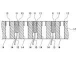
- FIG. 2 is a partially enlarged view of the A-A ′ cross section in the biomagnetic measurement apparatus shown in FIG. 1. It is explanatory drawing which overlap
- FIG. 10 is a perspective view showing a third modified example of the biomagnetism measuring device and an example in which a base in which the biomagnetism measuring device is incorporated is replaced with another configuration.
- FIG. 1 is a plan view showing an example of a biomagnetic measurement apparatus according to an embodiment of the present invention.
- FIG. 2 is a partially enlarged view of the AA ′ cross section in the biomagnetism measuring apparatus shown in FIG.
- the biomagnetism measuring apparatus 1 includes a plurality of magnetic sensors 11 that detect biomagnetism, and a holding unit 12 that detachably holds the magnetic sensors 11. Frames 13 for detachably holding the magnetic sensor 11 are arranged in an array on the holding unit 12.
- the magnetic sensor 11 detects a magnetic field generated from a living body to be measured (hereinafter also referred to as “subject”).
- the magnetic sensor 11 include a giant magnetoresistive sensor (GMR sensor), a tunnel magnetoresistive sensor (TMR sensor), an anisotropic magnetoresistive sensor (AMR sensor), a magnetic impedance sensor (MI sensor), and a fluxgate sensor.
- the magnetic sensor 11 used in this embodiment may be any magnetic sensor as long as it can detect a magnetic field (normal component) of about 10 ⁇ 4 T (tesla) to 10 ⁇ 10 T (tesla). .
- the magnetic sensor 11 used in the present embodiment can obtain the same level of information as the SQUID sensor, can be used at room temperature, does not need to be placed in a dewar for storing cooling, and uses a SQUID sensor Compared with, it is easy to handle and close to the living body.
- the magnetic sensor 11 may or may not have wiring for signal exchange and power supply. However, as shown in FIG. 2, in the biomagnetism measuring apparatus 1, since the several magnetic sensor 11 is arrange
- the signal detected by the magnetic sensor 11 is sent to a calculation unit (not shown).
- biomagnetic information is generated from the signals detected by the magnetic sensors 11, converted into image information, and displayed on the display device.
- FIG. 1 a frame 13 that holds the magnetic sensor 11 in a detachable manner is arranged in an array (14 ⁇ 14) in the holding unit 12.
- FIG. 2 a plurality of through holes 14 into which the magnetic sensor 11 can be inserted are formed in the holding unit 12, and the magnetic sensor 11 is detachably held in the opening of the through hole 14 that faces the measurement target.
- a frame 13 is attached.
- the attachment mechanism for attaching the magnetic sensor 11 to the frame 13 is not particularly limited, and may be attached by a fixture such as a screw. Thereby, the magnetic sensor 11 can be attached to and detached from the holding portion 12 and the frame 13 so that the detection surface faces the living body.
- the holding part 12, the frame 13, and the fixture (not shown) described above are preferably made of a plastic material such as acrylic resin, a non-ferrous metal such as copper or brass, or a non-magnetic material such as wood. Even if the holding unit 12, the frame 13, the fixture, etc. vibrate due to the movement of the subject due to breathing or the like, the holding unit 12, the frame 13, the fixture is made of a non-magnetic material, thereby suppressing environmental magnetic fluctuations. Can do. Therefore, it is possible to suppress the influence of environmental magnetism fluctuations on the magnetic sensor 11.
- the measurer determines the number of magnetic sensors 11 required and the arrangement thereof according to the measurement target, for example, the body shape and part of the subject, and holds the predetermined magnetic sensor 11 in the holding unit of the biomagnetic measurement device 1. Attach to the optimal position of the frame 3 of 2.
- the magnetic sensor 11 may be inserted into the through hole 14 from below the holding portion 12 and the magnetic sensor 11 may be attached to the frame 13 with a fixture.
- the frame 13 arranged in a 6 ⁇ 7 array among the frames 13 arranged in a 14 ⁇ 14 array is used.
- 42 magnetic sensors 11 may be attached (see FIG. 3).
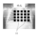
- 20 magnetic sensors 11 may be attached to the frame 13 arranged in a 5 ⁇ 4 array among the frames 13 arranged in a 14 ⁇ 14 array (FIG. 4). reference).
- 38 magnetic sensors 11 may be attached to the frame 13 arranged in a 5 ⁇ 1 + 7 ⁇ 4 + 5 ⁇ 1 array among the frames 13 arranged in a 14 ⁇ 14 array ( (See FIG. 5).
- the position of the frame 13 selected for mounting the magnetic sensor 11 is the peripheral part even if it is the central part of the holding unit 12.
- the central part is preferable from the viewpoint of the stability of the subject.
- the required resolution of the measurement result may be different.
- the magnetic sensors 11 may be densely arranged at locations where high resolution is required, and the magnetic sensors 11 may be sparsely arranged at locations where high resolution is not required. Good.
- the measurer guides the measurement site of the subject to be placed on the biomagnetism measuring device 1 on which the magnetic sensor 11 is arranged, and confirms whether the detection surface of the magnetic sensor 11 and the measurement target are in close contact with each other. Then, the biomagnetism measuring apparatus 1 is operated from an operation unit (not shown) to start measurement. Alternatively, the measurer guides the measurement site of the subject to be placed on the biomagnetism measuring apparatus 1 on which the magnetic sensor 11 is disposed, and then operates the biomagnetism measuring apparatus 1 to perform magnetism based on the detection result of the magnetic sensor 11. The arrangement of the magnetic sensor 11 may be readjusted while confirming whether or not the adhesion between the detection surface of the sensor 11 and the measurement target is obtained.
- the magnetic sensor 11 is arranged directly under the measurement target. Therefore, for example, the subject 100 may lie on his / her back on the medical table 2 in which the biomagnetic measurement device 1 is incorporated (see FIG. 6). Alternatively, the subject 100 may lie down on the medical table 2 (see FIG. 7).
- the subject 100 lies on the medical table 2 in which the biomagnetic measurement device 1 is incorporated, gravity acts on the subject 100 and the adhesion between the body surface of the subject 100 and the detection surface of the magnetic sensor 11 is improved. As a result, the biomagnetic measurement apparatus 1 can obtain biomagnetic information with higher accuracy.
- biomagnetic information can be obtained in the optimum region by arranging the magnetic sensor 11 at the optimum position according to the body shape / part of the subject (living body).
- problems such as the inability to obtain close contact between the magnetic sensor 11 and the living body and biomagnetic information cannot occur.
- the unnecessary magnetic sensor 11 since the unnecessary magnetic sensor 11 is not arranged, no signal exchange or power supply with the unnecessary magnetic sensor 11 is performed, and power saving and cost reduction are possible.
- the number of necessary magnetic sensors 11 can be reduced by attaching the magnetic sensors 11 to the optimum positions according to the required resolution of the measurement results. As a result, unnecessary signal exchange and power supply with the magnetic sensor 11 are not performed, and power saving and cost reduction are possible.
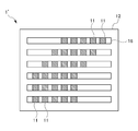
- FIG. 8 shows a first modification of the biomagnetic measurement apparatus.
- the magnetic sensor 11 is detachably held on the frame 13 of the holding unit 12, but may be held movably by a rail 16.
- the holding unit 12 is formed with a plurality of rails 16 that hold the magnetic sensor 11 in a movable manner in parallel. Thereby, the plurality of magnetic sensors 11 can be moved to arbitrary positions along the rails 16.
- the number of magnetic sensors 11 and rails 16 is not particularly limited, and may be appropriately selected depending on the measurement target.
- the magnetic sensor 11 may or may not be detachable from the rail 16.
- the rail 16 is preferably composed of a plastic material such as acrylic resin, a non-ferrous metal such as copper and brass, and a non-magnetic material such as wood, like the holding portion 12. Even if the holding unit 12, the rail 16 and the like vibrate due to the movement of the subject due to breathing or the like, the holding unit 12 and the rail 16 are made of a nonmagnetic material. Therefore, it is possible to suppress the influence of environmental magnetism fluctuations on the magnetic sensor 11.
- the measurer can easily move the magnetic sensor 11 along the rail 16 while checking the measurement result when measuring the biomagnetism of the subject. . That is, in the biomagnetism measuring apparatus 1 ′ in which the rail 16 is formed on the holding unit 12, the magnetic sensor 11 can be easily aligned at the time of measurement.
- FIG. 9 shows a second modification of the biomagnetic measurement apparatus.
- the holding unit 12 described above is a molded body in which a nonmagnetic material such as plastic is integrally formed, but the holding unit 17 may be made of a flexible material.
- the holding part 17 shown in FIG. 9 has a plurality of fixing parts 18 that individually fix the plurality of magnetic sensors 11 and a hinge 19 that connects the plurality of fixing parts 18 to each other. Since the hinge 19 is made of a flexible material such as rubber, the holding unit 17 can dispose the magnetic sensor 11 along the shape of the living body even when the living body has unevenness or curvature. And the detection surface of the magnetic sensor 11 can be brought into close contact with each other. As a result, the biomagnetism measuring apparatus including the holding unit 17 can accurately measure the magnetism of the living body. In addition, as long as the fixing
- FIG. 10 shows a third modification of the biomagnetic measurement apparatus.
- the biomagnetism measuring apparatus 1 shown in FIGS. 6 and 7 is configured to be incorporated in a medical table on which the subject 100 lies, but the table in which the biomagnetism measuring apparatus 1 is incorporated is not limited thereto.
- the biomagnetic measurement device 1 is incorporated into the measurement table 3 that is smaller than the medical table 2 as shown in FIG. Form may be sufficient.
- the measurement table 3 shown in FIG. 10 can detect the magnetism generated from the hand without the subject lying down, and can attach the magnetic sensor 11 to the optimum position according to the size of the hand and the necessary resolution. is there.
Landscapes
- Health & Medical Sciences (AREA)
- Life Sciences & Earth Sciences (AREA)
- Physics & Mathematics (AREA)
- Animal Behavior & Ethology (AREA)
- Medical Informatics (AREA)
- Veterinary Medicine (AREA)
- Public Health (AREA)
- Biophysics (AREA)
- Pathology (AREA)
- Engineering & Computer Science (AREA)
- Biomedical Technology (AREA)
- Heart & Thoracic Surgery (AREA)
- General Health & Medical Sciences (AREA)
- Molecular Biology (AREA)
- Surgery (AREA)
- Nuclear Medicine, Radiotherapy & Molecular Imaging (AREA)
- Radiology & Medical Imaging (AREA)
- Condensed Matter Physics & Semiconductors (AREA)
- General Physics & Mathematics (AREA)
- Measurement And Recording Of Electrical Phenomena And Electrical Characteristics Of The Living Body (AREA)
Abstract
本発明は、測定対象に応じて磁気センサを最適な位置に配置可能な生体磁気測定装置を提供することを目的とする。 本発明の生体磁気測定装置(1)は、生体磁気を検出する複数の磁気センサ(11)と、複数の磁気センサ(11)を生体に対向するように着脱可能に保持する枠(13)が形成された保持部(12)とを備える。また、本発明の生体磁気測定装置(1)は、生体磁気を検出する複数の磁気センサ(11)と、複数の磁気センサ(11)を生体に対向するように移動可能に保持するレール(16)が形成された保持部(12)とを備える。
Description
本発明は、磁気センサを用いた生体磁気測定装置に関する。
磁気を検出する磁気センサに関し、従来より、磁気抵抗効果素子(MR素子)を用いたMRセンサが知られている。磁界の強さに応じて、MR素子にかかる直流抵抗が変化する。この直流抵抗の変化の程度を利用して、MRセンサは、磁界の変化や磁性体の有無を電圧の変化として検出する。
MRセンサは、ハードディスク装置の磁気ヘッドや、回転センサ(エンコーダ)、位置センサとして広く利用されている。また、近年、スマートフォンやタブレット機器等のモバイル機器が普及しており、モバイル機器には地磁気を利用して方位を計測するMRセンサを用いた方位センサが内蔵されている。方位センサから得られる情報は、GPS(Global Positionning System)による位置情報を利用したナビゲーション等に用いられる。
しかしながら、これら工業応用分野では、高感度な磁気検出技術を必要としていない。例えば、回転センサや位置センサにおいては、磁石等を基準信号とするので、高感度の磁気検出を必須としていない。また、方位センサは、地磁気を基準として絶対方位を検出すれば足り、高感度の磁気検出を必須としていない。
ところで、近年、医療現場において、生体の脳、心臓、筋肉の電気活動に伴って発生する微弱な低周波の磁気を検出する脳磁計、心磁計、筋磁計といった生体磁気計測装置が使用されている。脳の電気的活動に伴って発生する脳磁は、地磁気の約1億分の1程度の強度であり、心臓の心筋の電気的活動に伴って発生する心磁は、地磁気の百万分の1程度の大きさである。そのため、生体が発生する磁気(以下、「生体磁気」ともいう。)を検出するに際し、磁気センサには、極めて高感度な検出性能が要求される。
高感度な磁気検出を可能にする高感度磁気センサとして、超電導量子干渉素子(Superconducting Quantum Interference Device、以下、「SQUID」ともいう。)が知られている(例えば、特許文献1参照。)。
SQUIDセンサは、超電導現象を利用した磁気センサであり、ジョセフソン接合を有する。そのため、SQUIDセンサを用いるに際し、液体ヘリウムや液体窒素といった冷媒による冷却を要する。したがって、SQUIDセンサは、冷媒を貯蔵するデュワー内に設けられなければならず、生体磁気を検出するにあたり、SQUIDセンサを生体と密着させることが難しい。
また、SQUIDセンサは、デュワー内にアレイ状に複数配置されている。しかしながら、SQUIDセンサを配置するにあたって、SQUIDセンサは、SQUID内部のジョセフソン接合に電磁気的な影響が及ばないように配置しなければならない。そのため、SQUIDセンサの配置変更、取替え、取り出し等は、容易ではない。
このように、SQUIDセンサは、超高感度な磁気センサであるにもかかわらず、生体に対して十分に近づけることができず、取り扱いが難しい等の課題がある。
そこで、冷却が不要な常温域で、微弱な磁気の検出が可能なMRセンサを用いた生体磁気測定装置が提案されている。例えば、特許文献2には、生体を外部磁場からシールドする被覆部材をヘルメット状又は円筒状に形成し、この被覆部材にMRセンサをアレイ状に内張りした生体磁気測定装置が提案されている。MRセンサを用いた生体磁気測定装置では、MRセンサをデュワー内に配置する必要がなく、SQUIDセンサを用いる場合に比べ、取り扱いが簡単で、MRセンサを生体に近づけやすい。
しかしながら、特許文献2に記載の生体磁気測定装置のように、MRセンサの位置が固定されていると、測定対象(生体)によっては、測定対象とMRセンサとの密着性がなくなり、MRセンサが磁気を検出できない場合がある。例えば、大人や子供、ヒト以外の動物等のように体型が異なる測定対象では、最適なMRセンサの配置が異なる。また、測定対象の部位によっては、それぞれ要求される測定結果の分解能も異なり、最適なMRセンサの配置が異なることがある。
本発明は、測定対象に応じて磁気センサを最適な位置に配置可能な生体磁気測定装置を提供することを目的とする。
本発明者らは、上記のような課題を解決するために鋭意研究を重ねた。その結果、複数の磁気センサを着脱可能又は移動可能に保持することにより、測定対象に応じて磁気センサを最適な位置に配置可能な生体磁気測定装置を提供できることを見出し、本発明を完成するに至った。具体的に、本発明は、以下のものを提供する。
(1)本発明は、生体磁気を検出する複数の磁気センサと、前記複数の磁気センサを生体に対向するように着脱可能又は移動可能に保持する保持部とを備える生体磁気測定装置である。
(2)また、本発明は、前記保持部には、前記磁気センサを着脱可能に保持する枠がアレイ状に配置されている、(1)に記載の生体磁気測定装置である。
(3)また、本発明は、前記保持部には、前記磁気センサをスライド移動可能に保持するレールが複数配置されている、(1)に記載の生体磁気測定装置である。
(4)また、本発明は、前記保持部は、非磁性材料から構成される、(1)から(3)のいずれかに記載の生体磁気測定装置である。
(5)また、本発明は、前記保持部は、可撓性材料から構成される、(1)から(4)のいずれかに記載の生体磁気測定装置である。
(6)また、本発明は、前記磁気センサが測定対象の直下に配される、(1)から(5)のいずれかに記載の生体磁気測定装置である。
本発明によれば、測定対象に応じて磁気センサを最適な位置に配置可能な生体磁気測定装置を提供することができる。
以下、本発明の実施形態について詳細に説明するが、本発明は、以下の実施形態に何ら限定されるものではなく、本発明の目的の範囲内において、適宜変更を加えて実施することができる。
<生体磁気測定装置1>
図1は、本発明の実施形態に係る生体磁気測定装置の一例を示す平面図である。図2は、図1に示す生体磁気測定装置におけるA-A’断面の部分拡大図である。図1に示すように、生体磁気測定装置1は、生体磁気を検出する複数の磁気センサ11と、磁気センサ11を着脱可能に保持する保持部12とを備えている。保持部12には、磁気センサ11を着脱可能に保持する枠13がアレイ状に配置されている。
図1は、本発明の実施形態に係る生体磁気測定装置の一例を示す平面図である。図2は、図1に示す生体磁気測定装置におけるA-A’断面の部分拡大図である。図1に示すように、生体磁気測定装置1は、生体磁気を検出する複数の磁気センサ11と、磁気センサ11を着脱可能に保持する保持部12とを備えている。保持部12には、磁気センサ11を着脱可能に保持する枠13がアレイ状に配置されている。
[磁気センサ11]
磁気センサ11は、測定対象である生体(以下、「被験者」ともいう。)から生じる磁界を検知する。磁気センサ11としては、巨大磁気抵抗センサ(GMRセンサ)、トンネル磁気抵抗センサ(TMRセンサ)、異方的磁気抵抗センサ(AMRセンサ)、磁気インピーダンスセンサ(MIセンサ)、フラックスゲートセンサ等が挙げられる。本実施形態で使用する磁気センサ11は、10-4T(テスラ)~10-10T(テスラ)程度の磁界(法線成分)を検出することができれば、いずれの磁気センサであってもよい。本実施形態で使用する磁気センサ11は、SQUIDセンサと同程度の情報を得ることができ、かつ、常温で使用可能で、冷却を貯蔵するデュワー内に配置する必要がなく、SQUIDセンサを用いる場合に比べ、取り扱いが簡単で、生体に近づけやすい。
磁気センサ11は、測定対象である生体(以下、「被験者」ともいう。)から生じる磁界を検知する。磁気センサ11としては、巨大磁気抵抗センサ(GMRセンサ)、トンネル磁気抵抗センサ(TMRセンサ)、異方的磁気抵抗センサ(AMRセンサ)、磁気インピーダンスセンサ(MIセンサ)、フラックスゲートセンサ等が挙げられる。本実施形態で使用する磁気センサ11は、10-4T(テスラ)~10-10T(テスラ)程度の磁界(法線成分)を検出することができれば、いずれの磁気センサであってもよい。本実施形態で使用する磁気センサ11は、SQUIDセンサと同程度の情報を得ることができ、かつ、常温で使用可能で、冷却を貯蔵するデュワー内に配置する必要がなく、SQUIDセンサを用いる場合に比べ、取り扱いが簡単で、生体に近づけやすい。
磁気センサ11は、信号の授受や電力供給のための配線を有していてもよいし、有していなくてもよい。ただし、図2に示すように、生体磁気測定装置1においては、複数の磁気センサ11が配置されることから、混線を避けるためには、配線15を有していることが好ましい。
上記磁気センサ11で検知された信号は、図示しない演算部に送られる。演算部では、各磁気センサ11で検知された信号から生体磁気情報を生成し、画像情報化して表示装置に表示出力する。
[保持部12・枠13]
図1に示すように、保持部12には、磁気センサ11を着脱可能に保持する枠13がアレイ状(14×14)に配置されている。図2に示すように、保持部12には、磁気センサ11を挿入可能な貫通孔14が複数形成され、貫通孔14の測定対象に対向する開口部には、磁気センサ11を着脱可能に保持する枠13が取り付けられている。磁気センサ11を枠13に取り付ける取付機構は、特に制限されるものでなく、ネジ等の固定具によって取り付けてもよい。これにより、磁気センサ11は、検知面が生体に対向するように、保持部12及び枠13に対して、着脱可能である。
図1に示すように、保持部12には、磁気センサ11を着脱可能に保持する枠13がアレイ状(14×14)に配置されている。図2に示すように、保持部12には、磁気センサ11を挿入可能な貫通孔14が複数形成され、貫通孔14の測定対象に対向する開口部には、磁気センサ11を着脱可能に保持する枠13が取り付けられている。磁気センサ11を枠13に取り付ける取付機構は、特に制限されるものでなく、ネジ等の固定具によって取り付けてもよい。これにより、磁気センサ11は、検知面が生体に対向するように、保持部12及び枠13に対して、着脱可能である。
上述した保持部12、枠13、及び固定具(図示せず)は、アクリル樹脂等のプラスチック材料、銅・真鍮等の非鉄金属、木材等の非磁性材料で構成されることが好ましい。呼吸等による被験者の動きによって、保持部12、枠13、固定具等が振動しても、保持部12、枠13、固定具が非磁性材料であることにより、環境磁気の変動を抑制することができる。よって、環境磁気の変動による影響が磁気センサ11に及ぶことを抑制することができる。
[生体磁気の測定手順]
以下、図3~図7を参照しながら、上記構成の生体磁気測定装置1を用いて生体磁気を測定する手順について説明する。
以下、図3~図7を参照しながら、上記構成の生体磁気測定装置1を用いて生体磁気を測定する手順について説明する。
まず、測定者は、測定対象、例えば、被験者の体型や部位に応じて、必要とされる磁気センサ11の個数とその配置を決定し、所定の磁気センサ11を生体磁気測定装置1の保持部2の枠3の最適な位置に取り付ける。磁気センサ11が信号授受のための配線15を有する場合には、保持部12の下方から磁気センサ11を貫通孔14に挿入し、磁気センサ11を固定具により枠13に取り付ければよい。
例えば、生体磁気測定装置1により、心磁図を得たい場合、被験者が大人のときには、14×14のアレイ状に配置された枠13のうち、6×7のアレイ状に配置された枠13に、42個の磁気センサ11を取り付ければよい(図3参照)。被験者が小人のときは、14×14のアレイ状に配置された枠13のうち、5×4のアレイ状に配置された枠13に、20個の磁気センサ11を取り付ければよい(図4参照)。生体が犬のときは、14×14のアレイ状に配置された枠13のうち、5×1+7×4+5×1のアレイ状に配置された枠13に38個の磁気センサ11を取り付ければよい(図5参照)。保持部12上の14×14のアレイ状に配置された枠13のうち、磁気センサ11を取り付けるために選択される枠13の位置は、保持部12の中央部であっても周辺部であってもよいが、被験者の安定性の点から、中央部であることが好ましい。
また、被験者の部位によっては、要求される測定結果の分解能が異なる場合もある。そのような場合には、図1に示すように、高分解能が必要である箇所に、磁気センサ11を密に配置し、高分解能が必要でない箇所に、磁気センサ11を疎に配置してもよい。
その後、測定者は、磁気センサ11が配置された生体磁気測定装置1に被験者の測定部位が載るように誘導し、磁気センサ11の検知面と測定対象との密着性が得られているかを確認し、図示しない操作部から生体磁気測定装置1を操作し、測定を開始する。または、測定者は、磁気センサ11が配置された生体磁気測定装置1に被験者の測定部位が載るように誘導した後、生体磁気測定装置1を操作し、磁気センサ11の検知結果に基づき、磁気センサ11の検知面と測定対象との密着性が得られているかを確認しながら、磁気センサ11の配置を再調整してもよい。
磁気センサ11の検知面と測定対象との密着性を高める上では、磁気センサ11が測定対象の直下に配されることが好ましい。よって、例えば、被験者100は、生体磁気測定装置1が組み込まれた診療台2上に仰向けに横たわってもよい(図6参照)。または、被験者100は診療台2上にうつ伏せで横たわってもよい(図7参照)。生体磁気測定装置1が組み込まれた診療台2に被験者100が横たわることにより、被験者100に重力が作用し、被験者100の体表面と磁気センサ11の検知面との密着性が向上する。その結果、生体磁気測定装置1は、より精度の高い生体磁気情報を得ることが可能となる。
このように、被験者(生体)の体型・部位に応じて、磁気センサ11を最適な位置に配置することにより、最適な領域で生体磁気情報を得ることができる。これにより、磁気センサ11と生体の密着性が得られず生体磁気情報が得られない等の不具合が発生しない。また、不要な磁気センサ11が配置されることもないので、不要な磁気センサ11との信号授受や電力供給も行われず、省電力化及び低コスト化が可能となる。
また、要求される測定結果の分解能に応じて、磁気センサ11を最適な位置に取り付けることにより、必要な磁気センサ11の個数を減らすことができる。これにより、不要な磁気センサ11との信号授受や電力供給も行われず、省電力化及び低コスト化が可能となる。
<生体磁気測定装置の変形例>
以下、図8~図10を参照しながら、本実施形態に係る生体磁気測定装置の変形例について説明する。なお、図8~図10中、上述した部材と同一部材には同一符号を付し、説明を省略する。
以下、図8~図10を参照しながら、本実施形態に係る生体磁気測定装置の変形例について説明する。なお、図8~図10中、上述した部材と同一部材には同一符号を付し、説明を省略する。
[第1の変形例]
図8は、生体磁気測定装置の第1の変形例を示す。図1及び図2に示す生体磁気測定装置1において、磁気センサ11は、保持部12の枠13に着脱可能に保持されているが、レール16によって移動可能に保持されていてもよい。
図8は、生体磁気測定装置の第1の変形例を示す。図1及び図2に示す生体磁気測定装置1において、磁気センサ11は、保持部12の枠13に着脱可能に保持されているが、レール16によって移動可能に保持されていてもよい。
(レール16)
図8に示す生体磁気測定装置1’において、保持部12には、磁気センサ11を移動可能に保持するレール16が複数本並列して形成されている。これにより、複数の磁気センサ11は、レール16に沿って任意の位置に移動可能である。磁気センサ11やレール16の数は、特に制限されず、測定対象によって適宜選択されればよい。磁気センサ11は、レール16に対して着脱可能であっても、可能でなくてもよい。
図8に示す生体磁気測定装置1’において、保持部12には、磁気センサ11を移動可能に保持するレール16が複数本並列して形成されている。これにより、複数の磁気センサ11は、レール16に沿って任意の位置に移動可能である。磁気センサ11やレール16の数は、特に制限されず、測定対象によって適宜選択されればよい。磁気センサ11は、レール16に対して着脱可能であっても、可能でなくてもよい。
レール16は、保持部12と同様に、アクリル樹脂等のプラスチック材料、銅・真鍮等の非鉄金属、木材等の非磁性材料で構成されることが好ましい。呼吸等による被験者の動きによって、保持部12、レール16等が振動しても、保持部12、レール16が非磁性材料であることにより、環境磁気の変動を抑制することができる。よって、環境磁気の変動による影響が磁気センサ11に及ぶことを抑制することができる。
保持部12にレール16が形成された生体磁気測定装置1’では、測定者は、被験者の生体磁気を測定する際、測定結果を確認しながら、磁気センサ11をレール16に沿って移動させやすい。すなわち、保持部12にレール16が形成された生体磁気測定装置1’では、測定時に、磁気センサ11の位置合わせを容易に行いやすい。
[第2の変形例]
図9は、生体磁気測定装置の第2の変形例を示す。上述した保持部12は、プラスチック等の非磁性材料が一体成形された成形体であったが、保持部17は、可撓性材料から構成されてもよい。
図9は、生体磁気測定装置の第2の変形例を示す。上述した保持部12は、プラスチック等の非磁性材料が一体成形された成形体であったが、保持部17は、可撓性材料から構成されてもよい。
図9に示す保持部17は、複数の磁気センサ11を個別に固定する複数の固定部18と、複数の固定部18同士を連結するヒンジ19とを有する。ヒンジ19がゴム等の可撓性材料から構成されることにより、保持部17は、生体に凹凸や曲率があっても、その形状に沿って磁気センサ11を配置可能であり、生体の体表面と磁気センサ11の検知面とを密着させることが可能である。その結果、保持部17を備えた生体磁気測定装置は、生体の磁気を精度よく測定することができる。なお、固定部18は、磁気センサ11を固定できれば、固定部18自体が可撓性材料から構成されてもよい。
[第3の変形例]
図10は、生体磁気測定装置の第3の変形例を示す。図6及び図7に示す生体磁気測定装置1は、被験者100が横たわれる診療台に組み込まれる形態であったが、生体磁気測定装置1が組み込まれる台は、これに限定されない。
図10は、生体磁気測定装置の第3の変形例を示す。図6及び図7に示す生体磁気測定装置1は、被験者100が横たわれる診療台に組み込まれる形態であったが、生体磁気測定装置1が組み込まれる台は、これに限定されない。
例えば、測定対象が被験者の四肢の一部(例えば、手)である場合には、図10に示すように、生体磁気測定装置1が診療台2よりも小型化された測定台3に組み込まれる形態であってもよい。図10に示す測定台3は、被験者が横たわることなく、手から生じる磁気を検出可能であり、手の大きさや、必要な分解能に応じて、磁気センサ11を最適な位置に取り付けることが可能である。
1 生体磁気測定装置
2 診療台
3 測定台
11 磁気センサ
12 保持部
13 枠
14 貫通孔
15 配線
16 レール
17 保持部
18 固定部
19 ヒンジ
2 診療台
3 測定台
11 磁気センサ
12 保持部
13 枠
14 貫通孔
15 配線
16 レール
17 保持部
18 固定部
19 ヒンジ
Claims (6)
- 生体磁気を検出する複数の磁気センサと、
前記複数の磁気センサを生体に対向するように着脱可能又は移動可能に保持する保持部とを備える生体磁気測定装置。 - 前記保持部には、前記磁気センサを着脱可能に保持する枠がアレイ状に配置されている、請求項1に記載の生体磁気測定装置。
- 前記保持部には、前記磁気センサをスライド移動可能に保持するレールが複数配置されている、請求項1に記載の生体磁気測定装置。
- 前記保持部は、非磁性材料から構成される、請求項1から3のいずれかに記載の生体磁気測定装置。
- 前記保持部は、可撓性材料から構成される、請求項1から4のいずれかに記載の生体磁気測定装置。
- 前記磁気センサが測定対象の直下に配される、請求項1から5のいずれかに記載の生体磁気測定装置。
Priority Applications (4)
| Application Number | Priority Date | Filing Date | Title |
|---|---|---|---|
| CN201780032459.1A CN109414212B (zh) | 2016-06-03 | 2017-06-02 | 生物磁测量装置 |
| JP2018521011A JP7075340B2 (ja) | 2016-06-03 | 2017-06-02 | 生体磁気測定装置 |
| EP17806823.5A EP3466333A4 (en) | 2016-06-03 | 2017-06-02 | BIOMAGNETISM MEASURING DEVICE |
| US16/306,069 US11647928B2 (en) | 2016-06-03 | 2017-06-02 | Biomagnetism measuring device |
Applications Claiming Priority (2)
| Application Number | Priority Date | Filing Date | Title |
|---|---|---|---|
| JP2016-112192 | 2016-06-03 | ||
| JP2016112192 | 2016-06-03 |
Publications (1)
| Publication Number | Publication Date |
|---|---|
| WO2017209273A1 true WO2017209273A1 (ja) | 2017-12-07 |
Family
ID=60478738
Family Applications (1)
| Application Number | Title | Priority Date | Filing Date |
|---|---|---|---|
| PCT/JP2017/020574 Ceased WO2017209273A1 (ja) | 2016-06-03 | 2017-06-02 | 生体磁気測定装置 |
Country Status (5)
| Country | Link |
|---|---|
| US (1) | US11647928B2 (ja) |
| EP (1) | EP3466333A4 (ja) |
| JP (1) | JP7075340B2 (ja) |
| CN (1) | CN109414212B (ja) |
| WO (1) | WO2017209273A1 (ja) |
Cited By (7)
| Publication number | Priority date | Publication date | Assignee | Title |
|---|---|---|---|---|
| JP2018051097A (ja) * | 2016-09-30 | 2018-04-05 | 国立大学法人 東京医科歯科大学 | 生体情報計測装置 |
| WO2019077865A1 (ja) * | 2017-10-16 | 2019-04-25 | 国立大学法人東京医科歯科大学 | 生体磁気計測装置 |
| JP2020089411A (ja) * | 2018-12-03 | 2020-06-11 | 朝日インテック株式会社 | 治療システム、および、画像生成方法 |
| JP2020094935A (ja) * | 2018-12-13 | 2020-06-18 | Tdk株式会社 | 磁界検出装置 |
| US11497425B2 (en) | 2019-03-08 | 2022-11-15 | Asahi Kasei Microdevices Corporation | Magnetic field measurement apparatus |
| US11927646B2 (en) | 2018-12-26 | 2024-03-12 | Asahi Kasei Microdevices Corporation | Magnetic field measuring apparatus |
| US12274538B2 (en) | 2018-08-22 | 2025-04-15 | Asahi Kasei Microdevices Corporation | Magnetic field measuring apparatus, magnetic field measuring method, and recording medium storing magnetic field measuring program |
Families Citing this family (10)
| Publication number | Priority date | Publication date | Assignee | Title |
|---|---|---|---|---|
| CN109561848B (zh) * | 2016-08-02 | 2023-03-10 | 国立大学法人东京医科齿科大学 | 生物磁测量装置 |
| CN110710966B (zh) * | 2019-11-12 | 2020-07-21 | 北京航空航天大学 | 一种用于测量人脑部磁场信号的吸盘式可穿戴柔性脑磁帽 |
| JP7468178B2 (ja) * | 2020-06-17 | 2024-04-16 | Tdk株式会社 | 磁気センサアレイ |
| WO2023105984A1 (ja) * | 2021-12-10 | 2023-06-15 | 株式会社島津製作所 | 生体磁気測定装置 |
| KR20230158955A (ko) | 2022-05-13 | 2023-11-21 | 엘지전자 주식회사 | 공기조화기 |
| KR20230158954A (ko) | 2022-05-13 | 2023-11-21 | 엘지전자 주식회사 | 공기조화기 |
| KR20230158959A (ko) | 2022-05-13 | 2023-11-21 | 엘지전자 주식회사 | 공기조화기 |
| KR20230158963A (ko) | 2022-05-13 | 2023-11-21 | 엘지전자 주식회사 | 공기조화기 |
| KR20230159258A (ko) | 2022-05-13 | 2023-11-21 | 엘지전자 주식회사 | 공기조화기 |
| CN116616775B (zh) * | 2023-05-06 | 2026-03-24 | 北京大学 | 一种测量实验动物生物磁场的可移动式探测装置 |
Citations (4)
| Publication number | Priority date | Publication date | Assignee | Title |
|---|---|---|---|---|
| JP2000041965A (ja) * | 1998-07-31 | 2000-02-15 | Toshiba Corp | 生体磁気計測装置 |
| JP2012020143A (ja) | 2006-02-23 | 2012-02-02 | Kanazawa Inst Of Technology | 超伝導磁気測定装置の制御方法 |
| JP2012095939A (ja) | 2010-11-05 | 2012-05-24 | Konica Minolta Holdings Inc | 生体磁気計測装置および方法 |
| JP2013244403A (ja) * | 2012-05-23 | 2013-12-09 | Seiko Epson Corp | 画像処理方法 |
Family Cites Families (10)
| Publication number | Priority date | Publication date | Assignee | Title |
|---|---|---|---|---|
| JPH0640868B2 (ja) * | 1991-08-19 | 1994-06-01 | 株式会社超伝導センサ研究所 | 生体磁場計測装置 |
| EP0884601B1 (en) * | 1997-06-11 | 2002-10-02 | Kanazawa Institute of Technology | Magnetometer |
| JP4077945B2 (ja) | 1998-08-11 | 2008-04-23 | 株式会社東芝 | 生体磁気計測装置 |
| JP3846675B2 (ja) * | 1999-06-29 | 2006-11-15 | 独立行政法人科学技術振興機構 | 生体内磁気測定による塵肺または肺機能画像化装置 |
| US7130675B2 (en) * | 2002-06-28 | 2006-10-31 | Tristan Technologies, Inc. | High-resolution magnetoencephalography system and method |
| US7603153B2 (en) * | 2005-12-12 | 2009-10-13 | Sterling Investments Lc | Multi-element probe array |
| KR101108134B1 (ko) * | 2009-09-14 | 2012-01-31 | 한국표준과학연구원 | 자기측정 센서용 수용장치 |
| JP5861703B2 (ja) | 2011-05-20 | 2016-02-16 | コニカミノルタ株式会社 | 磁気センサ及び生体磁気計測システム |
| JP2013124873A (ja) * | 2011-12-13 | 2013-06-24 | Seiko Epson Corp | 磁場測定装置及びセルアレイ |
| GB201211704D0 (en) * | 2012-07-02 | 2012-08-15 | Univ Leeds | Magnetometer for medical use |
-
2017
- 2017-06-02 CN CN201780032459.1A patent/CN109414212B/zh active Active
- 2017-06-02 EP EP17806823.5A patent/EP3466333A4/en not_active Ceased
- 2017-06-02 WO PCT/JP2017/020574 patent/WO2017209273A1/ja not_active Ceased
- 2017-06-02 US US16/306,069 patent/US11647928B2/en active Active
- 2017-06-02 JP JP2018521011A patent/JP7075340B2/ja active Active
Patent Citations (4)
| Publication number | Priority date | Publication date | Assignee | Title |
|---|---|---|---|---|
| JP2000041965A (ja) * | 1998-07-31 | 2000-02-15 | Toshiba Corp | 生体磁気計測装置 |
| JP2012020143A (ja) | 2006-02-23 | 2012-02-02 | Kanazawa Inst Of Technology | 超伝導磁気測定装置の制御方法 |
| JP2012095939A (ja) | 2010-11-05 | 2012-05-24 | Konica Minolta Holdings Inc | 生体磁気計測装置および方法 |
| JP2013244403A (ja) * | 2012-05-23 | 2013-12-09 | Seiko Epson Corp | 画像処理方法 |
Non-Patent Citations (1)
| Title |
|---|
| See also references of EP3466333A4 |
Cited By (12)
| Publication number | Priority date | Publication date | Assignee | Title |
|---|---|---|---|---|
| JP2018051097A (ja) * | 2016-09-30 | 2018-04-05 | 国立大学法人 東京医科歯科大学 | 生体情報計測装置 |
| WO2019077865A1 (ja) * | 2017-10-16 | 2019-04-25 | 国立大学法人東京医科歯科大学 | 生体磁気計測装置 |
| US11666261B2 (en) | 2017-10-16 | 2023-06-06 | National University Corporation Tokyo Medical And Dental University | Biomagnetism measurement device |
| US12274538B2 (en) | 2018-08-22 | 2025-04-15 | Asahi Kasei Microdevices Corporation | Magnetic field measuring apparatus, magnetic field measuring method, and recording medium storing magnetic field measuring program |
| JP2020089411A (ja) * | 2018-12-03 | 2020-06-11 | 朝日インテック株式会社 | 治療システム、および、画像生成方法 |
| WO2020116387A1 (ja) * | 2018-12-03 | 2020-06-11 | 朝日インテック株式会社 | 治療システム、および、画像生成方法 |
| JP7309350B2 (ja) | 2018-12-03 | 2023-07-18 | 朝日インテック株式会社 | 治療システム、および、画像生成方法 |
| US12220164B2 (en) | 2018-12-03 | 2025-02-11 | Asahi Intecc Co., Ltd. | Treatment system and image generation method |
| JP2020094935A (ja) * | 2018-12-13 | 2020-06-18 | Tdk株式会社 | 磁界検出装置 |
| JP7218560B2 (ja) | 2018-12-13 | 2023-02-07 | Tdk株式会社 | 磁界検出装置 |
| US11927646B2 (en) | 2018-12-26 | 2024-03-12 | Asahi Kasei Microdevices Corporation | Magnetic field measuring apparatus |
| US11497425B2 (en) | 2019-03-08 | 2022-11-15 | Asahi Kasei Microdevices Corporation | Magnetic field measurement apparatus |
Also Published As
| Publication number | Publication date |
|---|---|
| US20190133477A1 (en) | 2019-05-09 |
| CN109414212A (zh) | 2019-03-01 |
| CN109414212B (zh) | 2023-03-21 |
| EP3466333A4 (en) | 2020-03-04 |
| JPWO2017209273A1 (ja) | 2019-05-16 |
| JP7075340B2 (ja) | 2022-05-25 |
| US11647928B2 (en) | 2023-05-16 |
| EP3466333A1 (en) | 2019-04-10 |
Similar Documents
| Publication | Publication Date | Title |
|---|---|---|
| JP7075340B2 (ja) | 生体磁気測定装置 | |
| JP7036319B2 (ja) | 生体磁気測定装置 | |
| Hu et al. | A cubic 3-axis magnetic sensor array for wirelessly tracking magnet position and orientation | |
| US11666261B2 (en) | Biomagnetism measurement device | |
| US20190391213A1 (en) | Magnetic field measurement systems and methods of making and using | |
| JP5897719B2 (ja) | 磁気抵抗センサ、グラジオメータ | |
| FI83266C (fi) | Foerfarande och anordning foer lokalisering av elektroder faestade vid kroppen av en maenniska, i synnerhet huvudet. | |
| WO2020120924A1 (en) | Apparatus and method(s) in biomagnetic measurements | |
| US20130150702A1 (en) | Magnetic field measuring apparatus and cell array | |
| US20150369887A1 (en) | Methods and apparatuses related to instrumentation for magnetic relaxometry measurements | |
| US8232798B2 (en) | Magnetic tracking system for an imaging system | |
| CN104545866A (zh) | 包括磁通门传感器的心脏脉搏监测器 | |
| US20180172865A1 (en) | Dominant axis navigation sensor | |
| JP2002272695A (ja) | 汎用性を有する高感度磁気検出装置 | |
| Ohkubo | The emergence of non-cryogenic quantum magnetic sensors: Synergistic advancement in magnetography together with SQUID | |
| KR101104316B1 (ko) | 소동물의 심자도 측정 시스템 및 그 방법 | |
| JP2019136240A (ja) | 生体磁気計測装置及び生体磁気計測システム | |
| KR20080043413A (ko) | 생체자장계측장치 | |
| Schell et al. | Hall-effect magnetic tracking device for Magnetic Resonance Imaging | |
| JPH04109929A (ja) | 生体磁気計測法 | |
| Adachi et al. | Single triangular coil used to identify the position and orientation of a subject for biomagnetic measurements | |
| Adachi et al. | Evaluation of directional dependence of sensitivity for room-temperature magnetic flux sensors with wide sensitivity region | |
| Klarhöfer et al. | MR-compatible optical tracking device with active markers | |
| Ren et al. | Design of a data acquisition system on magnetic signal for magnetic localization and orientation system | |
| JP3407481B2 (ja) | 生体磁気計測装置 |
Legal Events
| Date | Code | Title | Description |
|---|---|---|---|
| ENP | Entry into the national phase |
Ref document number: 2018521011 Country of ref document: JP Kind code of ref document: A |
|
| 121 | Ep: the epo has been informed by wipo that ep was designated in this application |
Ref document number: 17806823 Country of ref document: EP Kind code of ref document: A1 |
|
| NENP | Non-entry into the national phase |
Ref country code: DE |
|
| ENP | Entry into the national phase |
Ref document number: 2017806823 Country of ref document: EP Effective date: 20190103 |