WO2017209273A1 - Dispositif de mesure de biomagnétisme - Google Patents
Dispositif de mesure de biomagnétisme Download PDFInfo
- Publication number
- WO2017209273A1 WO2017209273A1 PCT/JP2017/020574 JP2017020574W WO2017209273A1 WO 2017209273 A1 WO2017209273 A1 WO 2017209273A1 JP 2017020574 W JP2017020574 W JP 2017020574W WO 2017209273 A1 WO2017209273 A1 WO 2017209273A1
- Authority
- WO
- WIPO (PCT)
- Prior art keywords
- magnetic sensor
- sensor
- magnetic
- biomagnetism measuring
- biomagnetism
- Prior art date
- Legal status (The legal status is an assumption and is not a legal conclusion. Google has not performed a legal analysis and makes no representation as to the accuracy of the status listed.)
- Ceased
Links
Images






Classifications
-
- A—HUMAN NECESSITIES
- A61—MEDICAL OR VETERINARY SCIENCE; HYGIENE
- A61B—DIAGNOSIS; SURGERY; IDENTIFICATION
- A61B5/00—Measuring for diagnostic purposes; Identification of persons
- A61B5/05—Detecting, measuring or recording for diagnosis by means of electric currents or magnetic fields; Measuring using microwaves or radio waves
-
- G—PHYSICS
- G01—MEASURING; TESTING
- G01R—MEASURING ELECTRIC VARIABLES; MEASURING MAGNETIC VARIABLES
- G01R33/00—Arrangements or instruments for measuring magnetic variables
-
- G—PHYSICS
- G01—MEASURING; TESTING
- G01R—MEASURING ELECTRIC VARIABLES; MEASURING MAGNETIC VARIABLES
- G01R33/00—Arrangements or instruments for measuring magnetic variables
- G01R33/0094—Sensor arrays
-
- A—HUMAN NECESSITIES
- A61—MEDICAL OR VETERINARY SCIENCE; HYGIENE
- A61B—DIAGNOSIS; SURGERY; IDENTIFICATION
- A61B2562/00—Details of sensors; Constructional details of sensor housings or probes; Accessories for sensors
- A61B2562/02—Details of sensors specially adapted for in-vivo measurements
- A61B2562/0223—Magnetic field sensors
-
- A—HUMAN NECESSITIES
- A61—MEDICAL OR VETERINARY SCIENCE; HYGIENE
- A61B—DIAGNOSIS; SURGERY; IDENTIFICATION
- A61B2562/00—Details of sensors; Constructional details of sensor housings or probes; Accessories for sensors
- A61B2562/04—Arrangements of multiple sensors of the same type
- A61B2562/046—Arrangements of multiple sensors of the same type in a matrix array
-
- A—HUMAN NECESSITIES
- A61—MEDICAL OR VETERINARY SCIENCE; HYGIENE
- A61B—DIAGNOSIS; SURGERY; IDENTIFICATION
- A61B2562/00—Details of sensors; Constructional details of sensor housings or probes; Accessories for sensors
- A61B2562/16—Details of sensor housings or probes; Details of structural supports for sensors
-
- A—HUMAN NECESSITIES
- A61—MEDICAL OR VETERINARY SCIENCE; HYGIENE
- A61B—DIAGNOSIS; SURGERY; IDENTIFICATION
- A61B2576/00—Medical imaging apparatus involving image processing or analysis
- A61B2576/02—Medical imaging apparatus involving image processing or analysis specially adapted for a particular organ or body part
- A61B2576/023—Medical imaging apparatus involving image processing or analysis specially adapted for a particular organ or body part for the heart
-
- A—HUMAN NECESSITIES
- A61—MEDICAL OR VETERINARY SCIENCE; HYGIENE
- A61B—DIAGNOSIS; SURGERY; IDENTIFICATION
- A61B2576/00—Medical imaging apparatus involving image processing or analysis
- A61B2576/02—Medical imaging apparatus involving image processing or analysis specially adapted for a particular organ or body part
- A61B2576/026—Medical imaging apparatus involving image processing or analysis specially adapted for a particular organ or body part for the brain
-
- A—HUMAN NECESSITIES
- A61—MEDICAL OR VETERINARY SCIENCE; HYGIENE
- A61B—DIAGNOSIS; SURGERY; IDENTIFICATION
- A61B5/00—Measuring for diagnostic purposes; Identification of persons
- A61B5/40—Detecting, measuring or recording for evaluating the nervous system
- A61B5/4058—Detecting, measuring or recording for evaluating the nervous system for evaluating the central nervous system
- A61B5/4064—Evaluating the brain
Definitions
- the present invention relates to a biomagnetism measuring apparatus using a magnetic sensor.
- an MR sensor using a magnetoresistive effect element is known.
- the direct current resistance applied to the MR element changes according to the strength of the magnetic field.
- the MR sensor detects a change in the magnetic field and the presence or absence of a magnetic substance as a change in voltage.
- MR sensors are widely used as magnetic heads of hard disk devices, rotation sensors (encoders), and position sensors.
- mobile devices such as smartphones and tablet devices have become widespread, and mobile devices have built-in azimuth sensors using MR sensors that measure azimuth using geomagnetism.
- Information obtained from the azimuth sensor is used for navigation or the like using position information by GPS (Global Positioning System).
- biomagnetism measuring devices such as a magnetoencephalograph, a magnetocardiograph, and a magnetomagnetometer that detect weak low-frequency magnetism generated in association with the electrical activity of the brain, heart, and muscle of a living body are used in the medical field.
- the magnetoencephalogram generated by the electrical activity of the brain is about one hundred millionth the intensity of the geomagnetism
- the magnetocardiogram generated by the electrical activity of the heart's myocardium is one millionth of the geomagnetism.
- the size is about one. Therefore, when detecting magnetism generated by a living body (hereinafter also referred to as “biomagnetism”), the magnetic sensor is required to have extremely high detection performance.
- a superconducting quantum interference element (Superducting Quantum Interference Device, hereinafter also referred to as “SQUID”) is known (for example, see Patent Document 1).
- the SQUID sensor is a magnetic sensor using a superconducting phenomenon, and has a Josephson junction. Therefore, when using the SQUID sensor, cooling with a refrigerant such as liquid helium or liquid nitrogen is required. Therefore, the SQUID sensor must be provided in a dewar that stores the refrigerant, and it is difficult to bring the SQUID sensor into close contact with the living body when detecting biomagnetism.
- a plurality of SQUID sensors are arranged in an array in the dewar.
- the SQUID sensor when the SQUID sensor is disposed, the SQUID sensor must be disposed so as not to electromagnetically affect the Josephson junction inside the SQUID. For this reason, it is not easy to change, replace, and take out the SQUID sensor.
- the SQUID sensor is an ultra-sensitive magnetic sensor, there are problems such as being unable to be sufficiently close to the living body and being difficult to handle.
- Patent Document 2 proposes a biomagnetism measuring apparatus in which a covering member that shields a living body from an external magnetic field is formed in a helmet shape or a cylindrical shape, and an MR sensor is lined in an array shape on the covering member.
- a covering member that shields a living body from an external magnetic field is formed in a helmet shape or a cylindrical shape, and an MR sensor is lined in an array shape on the covering member.
- the optimal arrangement of MR sensors differs for measurement objects having different body shapes, such as adults, children, and animals other than humans.
- the required resolution of the measurement result is different, and the optimal arrangement of the MR sensor may be different.
- An object of the present invention is to provide a biomagnetism measuring apparatus capable of arranging a magnetic sensor at an optimum position according to a measurement object.
- the inventors of the present invention have intensively studied to solve the above problems. As a result, it has been found that by holding a plurality of magnetic sensors detachably or movably, it is possible to provide a biomagnetism measuring device capable of arranging the magnetic sensors in an optimum position according to the measurement target, and to complete the present invention. It came. Specifically, the present invention provides the following.
- the present invention is a biomagnetism measuring apparatus including a plurality of magnetic sensors for detecting biomagnetism and a holding unit that detachably or movably holds the plurality of magnetic sensors so as to face the living body.
- the present invention is the biomagnetism measuring device according to (1), wherein a frame for detachably holding the magnetic sensor is arranged in an array on the holding unit.
- the present invention is the biomagnetism measuring device according to (1), wherein a plurality of rails for slidably holding the magnetic sensor are arranged in the holding portion.
- the present invention is the biomagnetism measuring device according to any one of (1) to (3), wherein the holding unit is made of a nonmagnetic material.
- the present invention is the biomagnetism measuring device according to any one of (1) to (4), wherein the holding unit is made of a flexible material.
- the present invention is the biomagnetism measuring device according to any one of (1) to (5), wherein the magnetic sensor is arranged immediately below the measurement target.
- a biomagnetism measuring apparatus capable of arranging a magnetic sensor at an optimum position according to a measurement object.
- FIG. 2 is a partially enlarged view of the A-A ′ cross section in the biomagnetic measurement apparatus shown in FIG. 1. It is explanatory drawing which overlap
- FIG. 10 is a perspective view showing a third modified example of the biomagnetism measuring device and an example in which a base in which the biomagnetism measuring device is incorporated is replaced with another configuration.
- FIG. 1 is a plan view showing an example of a biomagnetic measurement apparatus according to an embodiment of the present invention.
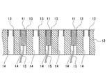
- FIG. 2 is a partially enlarged view of the AA ′ cross section in the biomagnetism measuring apparatus shown in FIG.
- the biomagnetism measuring apparatus 1 includes a plurality of magnetic sensors 11 that detect biomagnetism, and a holding unit 12 that detachably holds the magnetic sensors 11. Frames 13 for detachably holding the magnetic sensor 11 are arranged in an array on the holding unit 12.
- the magnetic sensor 11 detects a magnetic field generated from a living body to be measured (hereinafter also referred to as “subject”).
- the magnetic sensor 11 include a giant magnetoresistive sensor (GMR sensor), a tunnel magnetoresistive sensor (TMR sensor), an anisotropic magnetoresistive sensor (AMR sensor), a magnetic impedance sensor (MI sensor), and a fluxgate sensor.
- the magnetic sensor 11 used in this embodiment may be any magnetic sensor as long as it can detect a magnetic field (normal component) of about 10 ⁇ 4 T (tesla) to 10 ⁇ 10 T (tesla). .
- the magnetic sensor 11 used in the present embodiment can obtain the same level of information as the SQUID sensor, can be used at room temperature, does not need to be placed in a dewar for storing cooling, and uses a SQUID sensor Compared with, it is easy to handle and close to the living body.
- the magnetic sensor 11 may or may not have wiring for signal exchange and power supply. However, as shown in FIG. 2, in the biomagnetism measuring apparatus 1, since the several magnetic sensor 11 is arrange
- the signal detected by the magnetic sensor 11 is sent to a calculation unit (not shown).
- biomagnetic information is generated from the signals detected by the magnetic sensors 11, converted into image information, and displayed on the display device.
- FIG. 1 a frame 13 that holds the magnetic sensor 11 in a detachable manner is arranged in an array (14 ⁇ 14) in the holding unit 12.
- FIG. 2 a plurality of through holes 14 into which the magnetic sensor 11 can be inserted are formed in the holding unit 12, and the magnetic sensor 11 is detachably held in the opening of the through hole 14 that faces the measurement target.
- a frame 13 is attached.
- the attachment mechanism for attaching the magnetic sensor 11 to the frame 13 is not particularly limited, and may be attached by a fixture such as a screw. Thereby, the magnetic sensor 11 can be attached to and detached from the holding portion 12 and the frame 13 so that the detection surface faces the living body.
- the holding part 12, the frame 13, and the fixture (not shown) described above are preferably made of a plastic material such as acrylic resin, a non-ferrous metal such as copper or brass, or a non-magnetic material such as wood. Even if the holding unit 12, the frame 13, the fixture, etc. vibrate due to the movement of the subject due to breathing or the like, the holding unit 12, the frame 13, the fixture is made of a non-magnetic material, thereby suppressing environmental magnetic fluctuations. Can do. Therefore, it is possible to suppress the influence of environmental magnetism fluctuations on the magnetic sensor 11.
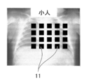
- the measurer determines the number of magnetic sensors 11 required and the arrangement thereof according to the measurement target, for example, the body shape and part of the subject, and holds the predetermined magnetic sensor 11 in the holding unit of the biomagnetic measurement device 1. Attach to the optimal position of the frame 3 of 2.
- the magnetic sensor 11 may be inserted into the through hole 14 from below the holding portion 12 and the magnetic sensor 11 may be attached to the frame 13 with a fixture.
- the frame 13 arranged in a 6 ⁇ 7 array among the frames 13 arranged in a 14 ⁇ 14 array is used.
- 42 magnetic sensors 11 may be attached (see FIG. 3).
- 20 magnetic sensors 11 may be attached to the frame 13 arranged in a 5 ⁇ 4 array among the frames 13 arranged in a 14 ⁇ 14 array (FIG. 4). reference).
- 38 magnetic sensors 11 may be attached to the frame 13 arranged in a 5 ⁇ 1 + 7 ⁇ 4 + 5 ⁇ 1 array among the frames 13 arranged in a 14 ⁇ 14 array ( (See FIG. 5).
- the position of the frame 13 selected for mounting the magnetic sensor 11 is the peripheral part even if it is the central part of the holding unit 12.
- the central part is preferable from the viewpoint of the stability of the subject.
- the required resolution of the measurement result may be different.
- the magnetic sensors 11 may be densely arranged at locations where high resolution is required, and the magnetic sensors 11 may be sparsely arranged at locations where high resolution is not required. Good.
- the measurer guides the measurement site of the subject to be placed on the biomagnetism measuring device 1 on which the magnetic sensor 11 is arranged, and confirms whether the detection surface of the magnetic sensor 11 and the measurement target are in close contact with each other. Then, the biomagnetism measuring apparatus 1 is operated from an operation unit (not shown) to start measurement. Alternatively, the measurer guides the measurement site of the subject to be placed on the biomagnetism measuring apparatus 1 on which the magnetic sensor 11 is disposed, and then operates the biomagnetism measuring apparatus 1 to perform magnetism based on the detection result of the magnetic sensor 11. The arrangement of the magnetic sensor 11 may be readjusted while confirming whether or not the adhesion between the detection surface of the sensor 11 and the measurement target is obtained.
- the magnetic sensor 11 is arranged directly under the measurement target. Therefore, for example, the subject 100 may lie on his / her back on the medical table 2 in which the biomagnetic measurement device 1 is incorporated (see FIG. 6). Alternatively, the subject 100 may lie down on the medical table 2 (see FIG. 7).
- the subject 100 lies on the medical table 2 in which the biomagnetic measurement device 1 is incorporated, gravity acts on the subject 100 and the adhesion between the body surface of the subject 100 and the detection surface of the magnetic sensor 11 is improved. As a result, the biomagnetic measurement apparatus 1 can obtain biomagnetic information with higher accuracy.
- biomagnetic information can be obtained in the optimum region by arranging the magnetic sensor 11 at the optimum position according to the body shape / part of the subject (living body).
- problems such as the inability to obtain close contact between the magnetic sensor 11 and the living body and biomagnetic information cannot occur.
- the unnecessary magnetic sensor 11 since the unnecessary magnetic sensor 11 is not arranged, no signal exchange or power supply with the unnecessary magnetic sensor 11 is performed, and power saving and cost reduction are possible.
- the number of necessary magnetic sensors 11 can be reduced by attaching the magnetic sensors 11 to the optimum positions according to the required resolution of the measurement results. As a result, unnecessary signal exchange and power supply with the magnetic sensor 11 are not performed, and power saving and cost reduction are possible.
- FIG. 8 shows a first modification of the biomagnetic measurement apparatus.
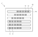
- the magnetic sensor 11 is detachably held on the frame 13 of the holding unit 12, but may be held movably by a rail 16.
- the holding unit 12 is formed with a plurality of rails 16 that hold the magnetic sensor 11 in a movable manner in parallel. Thereby, the plurality of magnetic sensors 11 can be moved to arbitrary positions along the rails 16.
- the number of magnetic sensors 11 and rails 16 is not particularly limited, and may be appropriately selected depending on the measurement target.
- the magnetic sensor 11 may or may not be detachable from the rail 16.
- the rail 16 is preferably composed of a plastic material such as acrylic resin, a non-ferrous metal such as copper and brass, and a non-magnetic material such as wood, like the holding portion 12. Even if the holding unit 12, the rail 16 and the like vibrate due to the movement of the subject due to breathing or the like, the holding unit 12 and the rail 16 are made of a nonmagnetic material. Therefore, it is possible to suppress the influence of environmental magnetism fluctuations on the magnetic sensor 11.
- the measurer can easily move the magnetic sensor 11 along the rail 16 while checking the measurement result when measuring the biomagnetism of the subject. . That is, in the biomagnetism measuring apparatus 1 ′ in which the rail 16 is formed on the holding unit 12, the magnetic sensor 11 can be easily aligned at the time of measurement.
- FIG. 9 shows a second modification of the biomagnetic measurement apparatus.
- the holding unit 12 described above is a molded body in which a nonmagnetic material such as plastic is integrally formed, but the holding unit 17 may be made of a flexible material.
- the holding part 17 shown in FIG. 9 has a plurality of fixing parts 18 that individually fix the plurality of magnetic sensors 11 and a hinge 19 that connects the plurality of fixing parts 18 to each other. Since the hinge 19 is made of a flexible material such as rubber, the holding unit 17 can dispose the magnetic sensor 11 along the shape of the living body even when the living body has unevenness or curvature. And the detection surface of the magnetic sensor 11 can be brought into close contact with each other. As a result, the biomagnetism measuring apparatus including the holding unit 17 can accurately measure the magnetism of the living body. In addition, as long as the fixing
- FIG. 10 shows a third modification of the biomagnetic measurement apparatus.
- the biomagnetism measuring apparatus 1 shown in FIGS. 6 and 7 is configured to be incorporated in a medical table on which the subject 100 lies, but the table in which the biomagnetism measuring apparatus 1 is incorporated is not limited thereto.
- the biomagnetic measurement device 1 is incorporated into the measurement table 3 that is smaller than the medical table 2 as shown in FIG. Form may be sufficient.
- the measurement table 3 shown in FIG. 10 can detect the magnetism generated from the hand without the subject lying down, and can attach the magnetic sensor 11 to the optimum position according to the size of the hand and the necessary resolution. is there.
Landscapes
- Health & Medical Sciences (AREA)
- Life Sciences & Earth Sciences (AREA)
- Physics & Mathematics (AREA)
- Animal Behavior & Ethology (AREA)
- Medical Informatics (AREA)
- Veterinary Medicine (AREA)
- Public Health (AREA)
- Biophysics (AREA)
- Pathology (AREA)
- Engineering & Computer Science (AREA)
- Biomedical Technology (AREA)
- Heart & Thoracic Surgery (AREA)
- General Health & Medical Sciences (AREA)
- Molecular Biology (AREA)
- Surgery (AREA)
- Nuclear Medicine, Radiotherapy & Molecular Imaging (AREA)
- Radiology & Medical Imaging (AREA)
- Condensed Matter Physics & Semiconductors (AREA)
- General Physics & Mathematics (AREA)
- Measurement And Recording Of Electrical Phenomena And Electrical Characteristics Of The Living Body (AREA)
Abstract
La présente invention vise à fournir un dispositif de mesure de biomagnétisme grâce auquel il est possible pour un capteur magnétique d'être disposé dans une position optimale en fonction d'un objet mesuré. Un dispositif de mesure de biomagnétisme (1) selon la présente invention comporte : une pluralité de capteurs magnétiques (11) qui détectent le biomagnétisme ; et une partie de maintien (12) dans laquelle sont formés des cadres (13) qui maintiennent de manière amovible la pluralité de capteurs magnétiques (11) de manière à faire face à un corps vivant. En outre, le dispositif de mesure de biomagnétisme (1) selon la présente invention comporte : une pluralité de capteurs magnétiques (11) qui détectent le biomagnétisme ; et une partie de maintien (12) dans laquelle sont formés des rails (16) qui maintiennent de manière mobile la pluralité de capteurs magnétiques (11) de manière à faire face à un corps vivant.
Priority Applications (4)
| Application Number | Priority Date | Filing Date | Title |
|---|---|---|---|
| CN201780032459.1A CN109414212B (zh) | 2016-06-03 | 2017-06-02 | 生物磁测量装置 |
| JP2018521011A JP7075340B2 (ja) | 2016-06-03 | 2017-06-02 | 生体磁気測定装置 |
| EP17806823.5A EP3466333A4 (fr) | 2016-06-03 | 2017-06-02 | Dispositif de mesure de biomagnétisme |
| US16/306,069 US11647928B2 (en) | 2016-06-03 | 2017-06-02 | Biomagnetism measuring device |
Applications Claiming Priority (2)
| Application Number | Priority Date | Filing Date | Title |
|---|---|---|---|
| JP2016-112192 | 2016-06-03 | ||
| JP2016112192 | 2016-06-03 |
Publications (1)
| Publication Number | Publication Date |
|---|---|
| WO2017209273A1 true WO2017209273A1 (fr) | 2017-12-07 |
Family
ID=60478738
Family Applications (1)
| Application Number | Title | Priority Date | Filing Date |
|---|---|---|---|
| PCT/JP2017/020574 Ceased WO2017209273A1 (fr) | 2016-06-03 | 2017-06-02 | Dispositif de mesure de biomagnétisme |
Country Status (5)
| Country | Link |
|---|---|
| US (1) | US11647928B2 (fr) |
| EP (1) | EP3466333A4 (fr) |
| JP (1) | JP7075340B2 (fr) |
| CN (1) | CN109414212B (fr) |
| WO (1) | WO2017209273A1 (fr) |
Cited By (7)
| Publication number | Priority date | Publication date | Assignee | Title |
|---|---|---|---|---|
| JP2018051097A (ja) * | 2016-09-30 | 2018-04-05 | 国立大学法人 東京医科歯科大学 | 生体情報計測装置 |
| WO2019077865A1 (fr) * | 2017-10-16 | 2019-04-25 | 国立大学法人東京医科歯科大学 | Dispositif de mesure de biomagnétisme |
| JP2020089411A (ja) * | 2018-12-03 | 2020-06-11 | 朝日インテック株式会社 | 治療システム、および、画像生成方法 |
| JP2020094935A (ja) * | 2018-12-13 | 2020-06-18 | Tdk株式会社 | 磁界検出装置 |
| US11497425B2 (en) | 2019-03-08 | 2022-11-15 | Asahi Kasei Microdevices Corporation | Magnetic field measurement apparatus |
| US11927646B2 (en) | 2018-12-26 | 2024-03-12 | Asahi Kasei Microdevices Corporation | Magnetic field measuring apparatus |
| US12274538B2 (en) | 2018-08-22 | 2025-04-15 | Asahi Kasei Microdevices Corporation | Magnetic field measuring apparatus, magnetic field measuring method, and recording medium storing magnetic field measuring program |
Families Citing this family (10)
| Publication number | Priority date | Publication date | Assignee | Title |
|---|---|---|---|---|
| CN109561848B (zh) * | 2016-08-02 | 2023-03-10 | 国立大学法人东京医科齿科大学 | 生物磁测量装置 |
| CN110710966B (zh) * | 2019-11-12 | 2020-07-21 | 北京航空航天大学 | 一种用于测量人脑部磁场信号的吸盘式可穿戴柔性脑磁帽 |
| JP7468178B2 (ja) * | 2020-06-17 | 2024-04-16 | Tdk株式会社 | 磁気センサアレイ |
| WO2023105984A1 (fr) * | 2021-12-10 | 2023-06-15 | 株式会社島津製作所 | Dispositif de mesure de biomagnétisme |
| KR20230158955A (ko) | 2022-05-13 | 2023-11-21 | 엘지전자 주식회사 | 공기조화기 |
| KR20230158954A (ko) | 2022-05-13 | 2023-11-21 | 엘지전자 주식회사 | 공기조화기 |
| KR20230158959A (ko) | 2022-05-13 | 2023-11-21 | 엘지전자 주식회사 | 공기조화기 |
| KR20230158963A (ko) | 2022-05-13 | 2023-11-21 | 엘지전자 주식회사 | 공기조화기 |
| KR20230159258A (ko) | 2022-05-13 | 2023-11-21 | 엘지전자 주식회사 | 공기조화기 |
| CN116616775B (zh) * | 2023-05-06 | 2026-03-24 | 北京大学 | 一种测量实验动物生物磁场的可移动式探测装置 |
Citations (4)
| Publication number | Priority date | Publication date | Assignee | Title |
|---|---|---|---|---|
| JP2000041965A (ja) * | 1998-07-31 | 2000-02-15 | Toshiba Corp | 生体磁気計測装置 |
| JP2012020143A (ja) | 2006-02-23 | 2012-02-02 | Kanazawa Inst Of Technology | 超伝導磁気測定装置の制御方法 |
| JP2012095939A (ja) | 2010-11-05 | 2012-05-24 | Konica Minolta Holdings Inc | 生体磁気計測装置および方法 |
| JP2013244403A (ja) * | 2012-05-23 | 2013-12-09 | Seiko Epson Corp | 画像処理方法 |
Family Cites Families (10)
| Publication number | Priority date | Publication date | Assignee | Title |
|---|---|---|---|---|
| JPH0640868B2 (ja) * | 1991-08-19 | 1994-06-01 | 株式会社超伝導センサ研究所 | 生体磁場計測装置 |
| EP0884601B1 (fr) * | 1997-06-11 | 2002-10-02 | Kanazawa Institute of Technology | Magnétomètre |
| JP4077945B2 (ja) | 1998-08-11 | 2008-04-23 | 株式会社東芝 | 生体磁気計測装置 |
| JP3846675B2 (ja) * | 1999-06-29 | 2006-11-15 | 独立行政法人科学技術振興機構 | 生体内磁気測定による塵肺または肺機能画像化装置 |
| US7130675B2 (en) * | 2002-06-28 | 2006-10-31 | Tristan Technologies, Inc. | High-resolution magnetoencephalography system and method |
| US7603153B2 (en) * | 2005-12-12 | 2009-10-13 | Sterling Investments Lc | Multi-element probe array |
| KR101108134B1 (ko) * | 2009-09-14 | 2012-01-31 | 한국표준과학연구원 | 자기측정 센서용 수용장치 |
| JP5861703B2 (ja) | 2011-05-20 | 2016-02-16 | コニカミノルタ株式会社 | 磁気センサ及び生体磁気計測システム |
| JP2013124873A (ja) * | 2011-12-13 | 2013-06-24 | Seiko Epson Corp | 磁場測定装置及びセルアレイ |
| GB201211704D0 (en) * | 2012-07-02 | 2012-08-15 | Univ Leeds | Magnetometer for medical use |
-
2017
- 2017-06-02 CN CN201780032459.1A patent/CN109414212B/zh active Active
- 2017-06-02 EP EP17806823.5A patent/EP3466333A4/fr not_active Ceased
- 2017-06-02 WO PCT/JP2017/020574 patent/WO2017209273A1/fr not_active Ceased
- 2017-06-02 US US16/306,069 patent/US11647928B2/en active Active
- 2017-06-02 JP JP2018521011A patent/JP7075340B2/ja active Active
Patent Citations (4)
| Publication number | Priority date | Publication date | Assignee | Title |
|---|---|---|---|---|
| JP2000041965A (ja) * | 1998-07-31 | 2000-02-15 | Toshiba Corp | 生体磁気計測装置 |
| JP2012020143A (ja) | 2006-02-23 | 2012-02-02 | Kanazawa Inst Of Technology | 超伝導磁気測定装置の制御方法 |
| JP2012095939A (ja) | 2010-11-05 | 2012-05-24 | Konica Minolta Holdings Inc | 生体磁気計測装置および方法 |
| JP2013244403A (ja) * | 2012-05-23 | 2013-12-09 | Seiko Epson Corp | 画像処理方法 |
Non-Patent Citations (1)
| Title |
|---|
| See also references of EP3466333A4 |
Cited By (12)
| Publication number | Priority date | Publication date | Assignee | Title |
|---|---|---|---|---|
| JP2018051097A (ja) * | 2016-09-30 | 2018-04-05 | 国立大学法人 東京医科歯科大学 | 生体情報計測装置 |
| WO2019077865A1 (fr) * | 2017-10-16 | 2019-04-25 | 国立大学法人東京医科歯科大学 | Dispositif de mesure de biomagnétisme |
| US11666261B2 (en) | 2017-10-16 | 2023-06-06 | National University Corporation Tokyo Medical And Dental University | Biomagnetism measurement device |
| US12274538B2 (en) | 2018-08-22 | 2025-04-15 | Asahi Kasei Microdevices Corporation | Magnetic field measuring apparatus, magnetic field measuring method, and recording medium storing magnetic field measuring program |
| JP2020089411A (ja) * | 2018-12-03 | 2020-06-11 | 朝日インテック株式会社 | 治療システム、および、画像生成方法 |
| WO2020116387A1 (fr) * | 2018-12-03 | 2020-06-11 | 朝日インテック株式会社 | Système de traitement et procédé de génération d'image |
| JP7309350B2 (ja) | 2018-12-03 | 2023-07-18 | 朝日インテック株式会社 | 治療システム、および、画像生成方法 |
| US12220164B2 (en) | 2018-12-03 | 2025-02-11 | Asahi Intecc Co., Ltd. | Treatment system and image generation method |
| JP2020094935A (ja) * | 2018-12-13 | 2020-06-18 | Tdk株式会社 | 磁界検出装置 |
| JP7218560B2 (ja) | 2018-12-13 | 2023-02-07 | Tdk株式会社 | 磁界検出装置 |
| US11927646B2 (en) | 2018-12-26 | 2024-03-12 | Asahi Kasei Microdevices Corporation | Magnetic field measuring apparatus |
| US11497425B2 (en) | 2019-03-08 | 2022-11-15 | Asahi Kasei Microdevices Corporation | Magnetic field measurement apparatus |
Also Published As
| Publication number | Publication date |
|---|---|
| US20190133477A1 (en) | 2019-05-09 |
| CN109414212A (zh) | 2019-03-01 |
| CN109414212B (zh) | 2023-03-21 |
| EP3466333A4 (fr) | 2020-03-04 |
| JPWO2017209273A1 (ja) | 2019-05-16 |
| JP7075340B2 (ja) | 2022-05-25 |
| US11647928B2 (en) | 2023-05-16 |
| EP3466333A1 (fr) | 2019-04-10 |
Similar Documents
| Publication | Publication Date | Title |
|---|---|---|
| JP7075340B2 (ja) | 生体磁気測定装置 | |
| JP7036319B2 (ja) | 生体磁気測定装置 | |
| Hu et al. | A cubic 3-axis magnetic sensor array for wirelessly tracking magnet position and orientation | |
| US11666261B2 (en) | Biomagnetism measurement device | |
| US20190391213A1 (en) | Magnetic field measurement systems and methods of making and using | |
| JP5897719B2 (ja) | 磁気抵抗センサ、グラジオメータ | |
| FI83266C (fi) | Foerfarande och anordning foer lokalisering av elektroder faestade vid kroppen av en maenniska, i synnerhet huvudet. | |
| WO2020120924A1 (fr) | Appareil et méthode(s) de mesures biomagnétiques | |
| US20130150702A1 (en) | Magnetic field measuring apparatus and cell array | |
| US20150369887A1 (en) | Methods and apparatuses related to instrumentation for magnetic relaxometry measurements | |
| US8232798B2 (en) | Magnetic tracking system for an imaging system | |
| CN104545866A (zh) | 包括磁通门传感器的心脏脉搏监测器 | |
| US20180172865A1 (en) | Dominant axis navigation sensor | |
| JP2002272695A (ja) | 汎用性を有する高感度磁気検出装置 | |
| Ohkubo | The emergence of non-cryogenic quantum magnetic sensors: Synergistic advancement in magnetography together with SQUID | |
| KR101104316B1 (ko) | 소동물의 심자도 측정 시스템 및 그 방법 | |
| JP2019136240A (ja) | 生体磁気計測装置及び生体磁気計測システム | |
| KR20080043413A (ko) | 생체자장계측장치 | |
| Schell et al. | Hall-effect magnetic tracking device for Magnetic Resonance Imaging | |
| JPH04109929A (ja) | 生体磁気計測法 | |
| Adachi et al. | Single triangular coil used to identify the position and orientation of a subject for biomagnetic measurements | |
| Adachi et al. | Evaluation of directional dependence of sensitivity for room-temperature magnetic flux sensors with wide sensitivity region | |
| Klarhöfer et al. | MR-compatible optical tracking device with active markers | |
| Ren et al. | Design of a data acquisition system on magnetic signal for magnetic localization and orientation system | |
| JP3407481B2 (ja) | 生体磁気計測装置 |
Legal Events
| Date | Code | Title | Description |
|---|---|---|---|
| ENP | Entry into the national phase |
Ref document number: 2018521011 Country of ref document: JP Kind code of ref document: A |
|
| 121 | Ep: the epo has been informed by wipo that ep was designated in this application |
Ref document number: 17806823 Country of ref document: EP Kind code of ref document: A1 |
|
| NENP | Non-entry into the national phase |
Ref country code: DE |
|
| ENP | Entry into the national phase |
Ref document number: 2017806823 Country of ref document: EP Effective date: 20190103 |