WO2017211331A1 - Dispositif et procédé pour une radiothérapie par impulsions à dose élevée avec une imagerie en temps réel - Google Patents
Dispositif et procédé pour une radiothérapie par impulsions à dose élevée avec une imagerie en temps réel Download PDFInfo
- Publication number
- WO2017211331A1 WO2017211331A1 PCT/CZ2017/050023 CZ2017050023W WO2017211331A1 WO 2017211331 A1 WO2017211331 A1 WO 2017211331A1 CZ 2017050023 W CZ2017050023 W CZ 2017050023W WO 2017211331 A1 WO2017211331 A1 WO 2017211331A1
- Authority
- WO
- WIPO (PCT)
- Prior art keywords
- laser
- pulse
- imaging
- diagnostic
- radiation
- Prior art date
- Legal status (The legal status is an assumption and is not a legal conclusion. Google has not performed a legal analysis and makes no representation as to the accuracy of the status listed.)
- Ceased
Links
Images



Classifications
-
- A—HUMAN NECESSITIES
- A61—MEDICAL OR VETERINARY SCIENCE; HYGIENE
- A61N—ELECTROTHERAPY; MAGNETOTHERAPY; RADIATION THERAPY; ULTRASOUND THERAPY
- A61N5/00—Radiation therapy
- A61N5/10—X-ray therapy; Gamma-ray therapy; Particle-irradiation therapy
- A61N5/1048—Monitoring, verifying, controlling systems and methods
- A61N5/1071—Monitoring, verifying, controlling systems and methods for verifying the dose delivered by the treatment plan
-
- A—HUMAN NECESSITIES
- A61—MEDICAL OR VETERINARY SCIENCE; HYGIENE
- A61N—ELECTROTHERAPY; MAGNETOTHERAPY; RADIATION THERAPY; ULTRASOUND THERAPY
- A61N5/00—Radiation therapy
- A61N5/06—Radiation therapy using light
-
- A—HUMAN NECESSITIES
- A61—MEDICAL OR VETERINARY SCIENCE; HYGIENE
- A61N—ELECTROTHERAPY; MAGNETOTHERAPY; RADIATION THERAPY; ULTRASOUND THERAPY
- A61N5/00—Radiation therapy
- A61N5/10—X-ray therapy; Gamma-ray therapy; Particle-irradiation therapy
- A61N5/1048—Monitoring, verifying, controlling systems and methods
- A61N5/1064—Monitoring, verifying, controlling systems and methods for adjusting radiation treatment in response to monitoring
- A61N5/1065—Beam adjustment
- A61N5/1067—Beam adjustment in real time, i.e. during treatment
-
- A—HUMAN NECESSITIES
- A61—MEDICAL OR VETERINARY SCIENCE; HYGIENE
- A61N—ELECTROTHERAPY; MAGNETOTHERAPY; RADIATION THERAPY; ULTRASOUND THERAPY
- A61N5/00—Radiation therapy
- A61N5/10—X-ray therapy; Gamma-ray therapy; Particle-irradiation therapy
- A61N5/1048—Monitoring, verifying, controlling systems and methods
- A61N5/1075—Monitoring, verifying, controlling systems and methods for testing, calibrating, or quality assurance of the radiation treatment apparatus
-
- A—HUMAN NECESSITIES
- A61—MEDICAL OR VETERINARY SCIENCE; HYGIENE
- A61N—ELECTROTHERAPY; MAGNETOTHERAPY; RADIATION THERAPY; ULTRASOUND THERAPY
- A61N5/00—Radiation therapy
- A61N5/10—X-ray therapy; Gamma-ray therapy; Particle-irradiation therapy
- A61N5/1048—Monitoring, verifying, controlling systems and methods
- A61N5/1049—Monitoring, verifying, controlling systems and methods for verifying the position of the patient with respect to the radiation beam
- A61N2005/1061—Monitoring, verifying, controlling systems and methods for verifying the position of the patient with respect to the radiation beam using an x-ray imaging system having a separate imaging source
-
- A—HUMAN NECESSITIES
- A61—MEDICAL OR VETERINARY SCIENCE; HYGIENE
- A61N—ELECTROTHERAPY; MAGNETOTHERAPY; RADIATION THERAPY; ULTRASOUND THERAPY
- A61N5/00—Radiation therapy
- A61N5/10—X-ray therapy; Gamma-ray therapy; Particle-irradiation therapy
- A61N2005/1085—X-ray therapy; Gamma-ray therapy; Particle-irradiation therapy characterised by the type of particles applied to the patient
- A61N2005/1087—Ions; Protons
- A61N2005/1088—Ions; Protons generated by laser radiation
-
- A—HUMAN NECESSITIES
- A61—MEDICAL OR VETERINARY SCIENCE; HYGIENE
- A61N—ELECTROTHERAPY; MAGNETOTHERAPY; RADIATION THERAPY; ULTRASOUND THERAPY
- A61N5/00—Radiation therapy
- A61N5/10—X-ray therapy; Gamma-ray therapy; Particle-irradiation therapy
- A61N2005/1085—X-ray therapy; Gamma-ray therapy; Particle-irradiation therapy characterised by the type of particles applied to the patient
- A61N2005/1089—Electrons
-
- A—HUMAN NECESSITIES
- A61—MEDICAL OR VETERINARY SCIENCE; HYGIENE
- A61N—ELECTROTHERAPY; MAGNETOTHERAPY; RADIATION THERAPY; ULTRASOUND THERAPY
- A61N5/00—Radiation therapy
- A61N5/10—X-ray therapy; Gamma-ray therapy; Particle-irradiation therapy
- A61N2005/1085—X-ray therapy; Gamma-ray therapy; Particle-irradiation therapy characterised by the type of particles applied to the patient
- A61N2005/109—Neutrons
-
- A—HUMAN NECESSITIES
- A61—MEDICAL OR VETERINARY SCIENCE; HYGIENE
- A61N—ELECTROTHERAPY; MAGNETOTHERAPY; RADIATION THERAPY; ULTRASOUND THERAPY
- A61N5/00—Radiation therapy
- A61N5/06—Radiation therapy using light
- A61N5/067—Radiation therapy using light using laser light
-
- A—HUMAN NECESSITIES
- A61—MEDICAL OR VETERINARY SCIENCE; HYGIENE
- A61N—ELECTROTHERAPY; MAGNETOTHERAPY; RADIATION THERAPY; ULTRASOUND THERAPY
- A61N5/00—Radiation therapy
- A61N5/10—X-ray therapy; Gamma-ray therapy; Particle-irradiation therapy
- A61N5/103—Treatment planning systems
- A61N5/1039—Treatment planning systems using functional images, e.g. PET or MRI
-
- G—PHYSICS
- G01—MEASURING; TESTING
- G01J—MEASUREMENT OF INTENSITY, VELOCITY, SPECTRAL CONTENT, POLARISATION, PHASE OR PULSE CHARACTERISTICS OF INFRARED, VISIBLE OR ULTRAVIOLET LIGHT; COLORIMETRY; RADIATION PYROMETRY
- G01J11/00—Measuring the characteristics of individual optical pulses or of optical pulse trains
-
- G—PHYSICS
- G01—MEASURING; TESTING
- G01T—MEASUREMENT OF NUCLEAR OR X-RADIATION
- G01T1/00—Measuring X-radiation, gamma radiation, corpuscular radiation, or cosmic radiation
- G01T1/29—Measurement performed on radiation beams, e.g. position or section of the beam; Measurement of spatial distribution of radiation
Definitions
- Radiotherapy is an important treatment for many types of cancer. This technique relies on the use of radiation sources to deliver dose to a target region within the patient’s body. Furthermore, radiotherapy is not restricted only to cancer treatment, but can be applied in general to deliver dose to a target region within the patient’s body as in the case, for example, of radiosurgery.
- radio frequency accelerators are devices capable of delivering electron or gamma beams with energy typically in the range 6-30 MeV. Due to their technology, these devices usually deliver very wide beams on the order of 10x10 cm2 and a dose rate of few Gy/min. Typically, such devices deliver to the target region 0.1-1 mGy per pulse, at a frequency of few hundreds Hz. Treatments with these devices usually last at least few minutes. During this time the target region within the patient’s body can move, due, for example, to patient’s breathing. For this reason huge effort is put in imaging the target region during the treatment.
- Patent US 9,044,604 discloses a radiotherapy system including a radiotherapy module and at least one X-ray imaging module. Using radio frequency accelerators, due to the low dose per pulse and to the high number of pulses needed, it is not feasible to perform radiography at each irradiation step. One of the reasons is that each radiography delivers additional dose to the patient.
- Patent US 8,039,819 discloses a device for creating a spatial dose distribution in a medium volume, the device comprising a laser system and at least one electron source for releasing a plurality of high-energy quasi-monoenergetic electron pulses upon irradiation with said laser pulses.
- the disclosed device produces ultra-short radiation pulses ( ⁇ 1 ms) with very high energy (> 50 MeV), but it is lacking a synchronized imaging system and a feedback control that exploits the treatment effectiveness due to the shortness of the radiation pulses.
- the present invention provides a system for radiotherapy which comprises at least one pulsed radiation source for delivering radiation pulses shorter than 1 ms, at least one imaging system, at least one control system for determining the deposited dose, and at least one synchronization system for synchronizing said pulsed radiation source and said imaging system within a time jitter shorter than 200 ms, wherein said pulsed radiation source is capable of delivering a dose of at least 50 mGy at a depth of at least 1 cm in water within a single pulse, wherein said imaging system has the time resolution better than 200 ms, and wherein said control system is connected to the pulsed radiation source and to the imaging system.
- a synchronized imaging system it is possible to gain information about the position, and eventually the shape, of the target region during each irradiation time step.
- This synchronized imaging helps to understand how precisely the target region has been irradiated, and this information can be used for improving the dose delivery in the subsequent pulses.
- this imaging may be used to foresee the target region position, and eventually shape, for the following radiation pulses.
- the target region irradiation and imaging happens in a time window smaller than 400 ms. Said time resolution is short enough that most of the patient’s body internal structure can be considered still.
- a map of the dose deposited into the patient’s body can be reconstructed with a very high accuracy due to the fact that the patient is still during the whole irradiation and imaging process.
- the reconstruction of the deposited dose map can be done either after each radiation pulse, after few of them or after the whole treatment session.
- the advantage is that this provides a better understanding of where the dose has been really deposited into the patient’s body.
- performing a reconstruction of the dose deposited after one or more radiation pulses, and adjusting the treatment plan according to this information after one or more pulses can lead to an higher dose deposited into the target region and to a lower dose deposited in the surroundings of the target region, inside the patient’s body.
- This method can be more effective than conventional methods in performing a more personalized treatment.
- the synchronization system is an electrical device capable of sending electrical pulses synchronized with a tunable delay within a time resolution better than 200 ms.
- the pulsed radiation source creates and delivers radiation beams to the patient.
- Each pulse of radiation is shorter than 1 ms and delivers a dose of at least 50 mGy at a depth of at least 1 cm in water.
- the pulsed radiation source can preferably be selected from the group comprising sources of electron beams, sources of high energy photon beams, sources of positron beams, sources of neutron beams, sources of pi meson beams, sources of beams comprising combinations of these particles.
- the pulsed radiation source can in one embodiment comprise a laser plasma electron accelerator.
- the electron beam emitted from the accelerator can be used as the radiation beam, or may be converted in the pulsed radiation source into a beam of high energy photons, positrons, neutrons or pi mesons, or of a mixture of these particles.
- the pulsed radiation source may comprise a laser emission system, a laser transport, a laser focusing system, a plasma electron accelerator, a radiation beam delivery system.
- the radiation beam delivery system is adapted for checking the electron beam quality and/or stopping or modifying the beam in order to achieve pre-determined criteria (e.g., determined by the treatment plan).
- the radiation beam delivery system may use the kinetic energy of the electron beam to create a different particle beam, for example a beam of high energy photons, positrons, neutrons or pi mesons.
- the laser emission system is a Ti:Sa laser, for delivering laser pulses with energy of at least 100 mJ and pulse duration shorter than 1 ⁇ s; more particularly a Ti:Sa laser, pumped by diode pumped solid state lasers with frequency conversion, for delivering laser pulses with energy of at least 100 mJ and pulse duration shorter than 1 ⁇ s.
- the laser transport comprises at least one system selected from: a compressor for compressing the laser pulse in time to less than 100 fs, and an optical transport line for sending the laser pulse to the laser focusing system; a compressor, an optical transport line and a phased optical fiber array for transporting an uncompressed laser pulse with time duration of at least 10 ps to the compressor, whereas the compressor is capable of compressing the laser pulse in time to less than 100 fs and then sending the laser pulse to the optical transport line for sending the laser pulse to the laser focusing system.
- the laser focusing system may be an optical system for focusing the laser pulses into the plasma electron accelerator, comprising at least one positioning mirror and at least one off-axis parabola capable of focusing the laser pulses to intensity higher than 10 12 W/cm 2 .
- the laser focusing system is an optical system for focusing the laser pulses into the plasma electron accelerator, comprising at least one positioning mirror and at least one spherical mirror capable of focusing the laser pulses to intensity higher than 10 12 W/cm 2 .
- the plasma electron accelerator is a device comprising at least one gas target mounted on a remotely controlled motorized stage with at least one degree of freedom to align the gas target according to the laser focus.
- the radiation beam delivery system comprises at least one of the following components: a magnetic field for selecting the energy of the beam and for optionally shaping the beam, a beam charge diagnostic, a magnetic system for changing the size of the beam, and optionally for focusing or defocusing it, and a solid target converter for generating other particle beams.
- the pulsed radiation source may preferably comprise at least one laser beam diagnostic, selected from: a spectral shape diagnostic for measuring the spectral shape of the laser pulse; an energy diagnostic for measuring the energy of the laser pulse; a beam shape diagnostic for measuring the energy distribution of the laser pulse along its transverse section; a spectral phase diagnostic for measuring the spectral phase of the laser pulse; a temporal profile diagnostic for measuring the temporal profile of the laser pulse; a laser focal spot diagnostic for measuring the spatial distribution of the laser pulse in its focus; and a wavefront diagnostic for measuring the phase front of the laser pulse.
- a spectral shape diagnostic for measuring the spectral shape of the laser pulse
- an energy diagnostic for measuring the energy of the laser pulse
- a beam shape diagnostic for measuring the energy distribution of the laser pulse along its transverse section
- a spectral phase diagnostic for measuring the spectral phase of the laser pulse
- a temporal profile diagnostic for measuring the temporal profile of the laser pulse
- a laser focal spot diagnostic for measuring the spatial distribution of the laser pulse in its focus
- the spectral shape diagnostic can be an optical and/or infrared light spectrometer.
- the energy diagnostic comprises a calorimeter; and/or at least one optical diode.
- the beam shape diagnostics comprises a set of mask filters; and/or a camera and imaging optics.
- the spectral phase diagnostic comprises at least one of the following devices: SPIDER, FROG, D-SCAN and GRENOUILLE.
- the electron beam shape diagnostic comprises a fluorescent screen coupled with a CCD.
- the electron beam charge diagnostic comprises at least one Integrating Current Transformer and/or at least one fluorescent screen coupled with a CCD.
- the electron beam spectral shape diagnostic comprises a magnetic dipole and a fluorescent screen coupled with a CCD.
- the laser focal spot diagnostic comprises a CCD and a reflective object.
- the pulsed radiation source may further comprise a gas target for emitting the electron pulses, which can optionally be monitored by one or more diagnostics selected from a plasma diagnostic for measuring the plasma density inside the target; a laser plasma coupling diagnostic for measuring the coupling in the laser plasma interaction; and a laser propagation diagnostic for measuring the laser propagation after the plasma.
- a gas target for emitting the electron pulses, which can optionally be monitored by one or more diagnostics selected from a plasma diagnostic for measuring the plasma density inside the target; a laser plasma coupling diagnostic for measuring the coupling in the laser plasma interaction; and a laser propagation diagnostic for measuring the laser propagation after the plasma.
- the electron pulses accelerated by the plasma electron accelerator can preferably be monitored by one or more diagnostics selected from an electron beam shape diagnostic for measuring the transverse shape of the electron pulse; a beam charge diagnostic for measuring the charge of the electron pulse; an electron beam spectral shape diagnostic for measuring the spectral shape of the electron pulse; a beam divergence diagnostic for measuring the divergence of the electron pulse; and a beam temporal profile diagnostic for measuring the temporal profile of the electron pulse.
- an electron beam shape diagnostic for measuring the transverse shape of the electron pulse
- a beam charge diagnostic for measuring the charge of the electron pulse
- an electron beam spectral shape diagnostic for measuring the spectral shape of the electron pulse
- a beam divergence diagnostic for measuring the divergence of the electron pulse
- a beam temporal profile diagnostic for measuring the temporal profile of the electron pulse.
- the laser propagation diagnostic comprises a CCD looking at the laser exiting the target.
- the beam divergence diagnostic comprises a fluorescent screen coupled with a CCD.
- the beam temporal profile diagnostic comprises an infrared spectrometer and a solid target.
- the pulsed radiation source may further comprise a control system for the electron beam optimization for collecting the data from all diagnostics, analyzing said data and optionally saving the results. If the electron beam does not satisfy the parameters required for the treatment, the control system for the electron beam optimization modifies the position or state of the pulsed radiation source components until the electron beam reaches the parameters desired.
- the spectral shaping device is a mazzler.
- the spectral shaping device comprises at least one colored optical filter; and/or at least one prism and at least one neutral optical filter.
- the energy attenuator comprises at least one half-lambda plate and at least one polarizer.
- the spectral phase shaper is a dazzler.
- the adaptive optics comprises a deformable mirror.
- the compressor gratings motors are at least one linear stage mounted below one of the gratings to change the optical path of the different wavelengths.
- the positioning motors are at least one actuator mounted on at least one mirror mount capable of moving with at least one degree of freedom the at least one positioning mirror.
- the focusing optics motors comprise at most five rotation stages and at most seven linear stages mounted below the focusing optics, capable of moving the focusing optics with at least one degree of freedom.
- the gas density shaper is a device capable of changing the spatial density of the gas target, comprising at least one of the following components: a gas pressure regulator, a gas mixture regulator, and at least one wire and/or at least one sharp edge, remotely controlled and eventually automatic, that modifies the trajectory of the supersonic gas jet, thus changing the plasma density profile.
- the gas target motors are a set of at least one linear stage capable of moving the gas target with at least one degree of freedom.
- the radiation spectrum fine shaper comprises at least one magnetic field and at least one slit.
- the radiation pulse particle number controller comprises at least one magnetic field and at least one slit.
- the radiation pulse particle number controller comprises at least one solid target and at least one slit.
- the radiation pulse spatial distribution shaper comprises at least one solid target.
- the radiation pulse divergence controller comprises at least one magnetic field and at least one slit.
- the radiation pulse divergence controller comprises at least one solid target and at least one slit.
- radiation pulse temporal profile controller comprises at least one magnetic field.
- radiation pulse temporal profile controller comprises at least one solid target.
- the device is controlled by a wireless device, for example a tablet or a laptop.
- the pulsed radiation source may, for example, comprise a laser master oscillator, a booster, a stretcher, a first amplifier, a laser pulse delivery system, a final amplifier, a laser transport, a laser focusing system, a plasma electron accelerator, a radiation beam delivery system.
- the pulsed radiation source may comprise one radiation arm or a plurality of radiation pulse arms, such as two, three, four, five, or more radiation pulse arms.
- Each of the radiation pulse arms may for example comprise a final amplifier, a laser transport, a laser focusing system, a plasma electron accelerator, a radiation beam delivery system.
- the laser master oscillator is a Ti:Sa oscillator.
- the booster comprises a laser pulse amplifier, for example a regenerative amplifier or a multi-pass amplifier.
- the stretcher is an optical device comprising at least one pair of diffractive gratings.
- the first amplifier and/or the final amplifier comprises a Ti:Sa crystal pumped by a diode pumped solid state laser with frequency conversion and/or a Ti:Sa crystal pumped by a flash lamp pumped solid state laser with frequency conversion.
- the laser pulse delivery system is an optical system composed by a set of fast flip mirrors. In another embodiment of the device, the laser pulse delivery system is a fast rotating mirror. In another embodiment of the device, the laser pulse delivery system comprises at least one galvo mirror.
- the imaging system is synchronized with the pulsed radiation source by means of the synchronization system within a time jitter shorter than 200 ms.
- the imaging system can be based on various imaging technologies known to the person skilled in the art. By way of example, x-ray imaging technology, magnetic resonance imaging (MRI) technology, ballistic and snake photon technology, fluorescent markers, or Cerenkov radiation detection can be used, or a combination of any two or more of these methods.
- real time magnetic resonance systems capable of imaging may be used to monitor the target region with a time resolution better than 200 ms.
- the MRI is synchronized to the radiation pulse by the synchronization system with a time jitter lower than 200 ms.
- x-ray imaging system wherein a synchronized x-ray source is adapted to emit x-ray for imaging in a time shorter than 200 ms.
- x-ray images are acquired with a time resolution better than 200 ms.
- the x-ray imaging system is synchronized to the radiation pulse by the synchronization system with a time jitter lower than 200 ms.
- the additional dose deposited into the patient’s body due to the imaging x-ray is typically in the range of 0.1-10 mSv per image, but can be lowered using special imaging techniques, as for example x-ray phase contrast imaging or x-ray fluoroscopy. This actually limits the maximum number of radiography steps that can be taken.
- Being capable of performing a treatment session with just few radiation pulses using the radiation source having the parameters set by the present invention provides an additional advantage over the radio frequency accelerators.
- the system of the present invention thus can perform x-ray imaging of the target region at each radiation pulse.
- the x-ray imaging system comprises an electron emitter, or cathode, which may be a wire undergoing a very high current, and an anode having a potential difference with respect to the cathode of at least 20 kV.
- the x-ray imaging system comprises a laser system for generating laser pulses focused on a solid, liquid, gaseous or plasma target.
- the x-ray imaging system comprises an x-ray delivery system capable of shaping the x-ray beam both in fluence and spectrum; said x-ray delivery system may be a stack of metal foils.
- the x-ray imaging system comprises a target position diagnostics, which may be a set of digital x-ray sensors connected with the control system.
- the target position diagnostics is preferably adapted to perform at least one of: x-ray absorption imaging, x-ray fluoroscopy imaging, x-ray phase contrast imaging.
- ballistic and snake photons medical imaging technique [1] system capable of acquiring images with a time resolution lower than 200 ms.
- an imaging system based on detecting the Cerenkov radiation emitted by the radiation beam when it enters and exits the patient’s body is used. This technique is very effective since the radiation is emitted in very short time ( ⁇ 1 ms).
- imaging system based on fluorescent markers.
- markers can be inserted into or near the target region and can be, for example, gold particles. The role of these markers is to either appear as a strong absorption object in the radiography, or to emit characteristic radiation once irradiated by the radiation pulse. These markers help in reducing the exposure time for the target region imaging.
- the imaging technologies in particular MRI and x-ray imaging technologies can be combined to get a more precise imaging. It is also preferable to combine any technique with fluorescent markers.
- the imaging can be two-dimensional or three-dimensional.
- the control system may include a control system for the electron beam optimization.
- the input and output of the control system for the electron beam optimization are connected with at least one component of the pulsed radiation source, for example with the laser plasma electron accelerator.
- control system and/or the control system for the electron beam optimization is a computer.
- the present invention also provides a method for testing and/or calibrating a system of the present invention, wherein a body of water (e.g., a water phantom) is irradiated by means of the pulsed radiation source by at least one pulse having the duration of less than 1 ms and depositing a dose corresponding to at least 50 mGy at a depth of at least 1 cm in water, and simultaneously the irradiated region is subjected to imaging by means of the imaging system within a time jitter shorter than 200 ms from the delivery of the irradiation pulse, wherein the imaging is carried out with a time resolution better than 200 ms, and the obtained image is used for calculating the deposited dose and optionally adjusting the system.
- a body of water e.g., a water phantom
- the present invention further provides a method for radiotherapeutics treatment of a subject in need of such treatment using the system of the present invention, wherein the subject is irradiated by means of the pulsed radiation source by at least one pulse having the duration of less than 1 ms and depositing a dose corresponding to at least 50 mGy at a depth of at least 1 cm in water, and simultaneously the subject is subjected to imaging by means of the imaging system within a time jitter shorter than 200 ms from the delivery of the irradiation pulse, wherein the imaging is carried out with a time resolution better than 200 ms, and the obtained image is used for calculating the deposited dose and optionally adjusting the treatment.
- This method is advantageous over existing solutions since it allows for a precise reconstruction of the dose deposited into the target region and the patient’s body. Moreover, it can be very effective in some specific cases like breast or lung tumor, where the target region is located in a fast moving region of the patient’s body. In such cases this method helps in understanding how well the tumor was hit by the radiation pulse, and which fraction of the radiation has been delivered to the healthy tissue of the patient.
- the imaging system can monitor the target region via time-resolved 2-D or 3-D images.
- gated radiotherapy technique is used for irradiation.
- the imaging used is Cerenkov imaging to detect the in and out position of the radiation beam.
- this method further comprises that after each radiation pulse, after few radiation pulses, or after the whole treatment session, the target region images are analyzed and the information about the position and, eventually, the shape of the target region are used in combination with the data relative to the radiation pulses to improve the treatment plan.
- FIG. 1 schematically illustrates one embodiment of the components of the device.
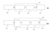
- FIG. 2 schematically illustrates two different configuration embodiments for the laser transport.
- FIG. 3 schematically illustrates one embodiment of the workflow of the control system of the device.
- FIG. 5 schematically illustrates one embodiment of the system with multiple radiation pulse arms mounted on robotic arms and multiple x-ray imaging modules mounted on static support, in particular with two radiation pulse arms and two x-ray imaging modules.
- FIG. 6 schematically illustrates one embodiment of the system with MRI imaging system, x-ray imaging system and two radiation pulse arms, in particular with one radiation pulse arm implemented in the MRI imaging system.
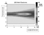
- FIG. 7 shows a 2-D plot of the dose deposited inside a 10x20 cm water phantom by one of the possible beams emitted by the pulsed radiation source.
- FIG. 1 schematically represents one possible embodiment of the system, in this specific case using x-ray imaging and a laser plasma electron accelerator.
- the synchronization system 101 synchronizes, with a time jitter lower than 200 ms, the emission of an x-ray pulse from the x-ray machine 107 and the emission of a laser pulse from the laser system 102 .
- the laser pulse is transported through the laser transport 103 , and then focused by the laser focusing system 104 into the plasma electron accelerator 105 .
- Each single electron beam generated in the plasma electron accelerator 105 goes into the radiation beam delivery system 106 , which operates on each electron pulse and sends to the target 110 a radiation pulse.
- the x-ray pulse coming from the x-ray machine 107 hits the target 110 within a time window shorter than 200 ms.
- the target position diagnostics 109 detect the x-ray signal coming from the x-ray delivery system 108 , after it passes through the target 110 .
- the synchronization system 101 is an electrical device capable of sending electrical pulses synchronized with a tunable delay with a time resolution better than 200 ms.
- the laser system 102 is a Ti:Sa laser, delivering laser pulses with energy of at least 100 mJ and pulse duration shorter than 1 ⁇ s.
- the laser system 102 is a Ti:Sa laser, pumped by diode pumped solid state lasers with frequency conversion, delivering laser pulses with energy of at least 100 mJ and pulse duration shorter than 1 ⁇ s.
- the laser transport 103 comprises the compressor 202 , which compresses the laser pulse in time to less than 100 fs, and the transport 203 , which is an optical transport line that sends the laser pulse to the laser focusing system 104 .
- the laser transport 103 comprises a phased optical fiber array 201 , which transports the uncompressed laser pulse, which has time duration of at least 10 ps, to the compressor 202 .
- the compressor 202 compresses the laser pulse in time to less than 100 fs and then it sends the laser pulse to the transport 203 , which is an optical transport line that sends the laser pulse to the laser focusing system 104 .
- the laser focusing system 104 is an optical system that focuses the laser pulse inside the plasma electron accelerator 105 , comprising at least one positioning mirror and at least one off-axis parabola capable of focusing the laser pulse to intensity higher than 10 12 W/cm 2 .
- the laser focusing system 104 is an optical system that focuses the laser pulse inside the plasma electron accelerator 105 , comprising at least one positioning mirror and at least one spherical mirror capable of focusing the laser pulse to intensity higher than 10 12 W/cm 2 .
- the plasma electron accelerator 105 is a device comprising at least one gas target mounted on a remotely controlled motorized stage with at least one degree of freedom to align the gas target according to the laser focus.
- the radiation beam delivery system 106 is a device comprising at least one of the following components: a magnetic field to select the energy of the electron beam and to eventually shape the electron beam, a beam charge diagnostic, a magnetic system to change the size of the electron beam, and eventually focus or defocus it, and a solid target to change the beam divergence and/or to generate other particle beams, for example high energy photons (x-ray and gamma-ray), positrons, neutrons or pi mesons.
- a magnetic field to select the energy of the electron beam and to eventually shape the electron beam
- a beam charge diagnostic to change the size of the electron beam, and eventually focus or defocus it
- a solid target to change the beam divergence and/or to generate other particle beams, for example high energy photons (x-ray and gamma-ray), positrons, neutrons or pi mesons.
- the x-ray machine 107 is a device comprising an electron emitter, or cathode, which may be a wire undergoing a current higher than 1 ⁇ A, and an anode having a potential difference with respect to the cathode of at least 20 kV.
- the x-ray machine 107 is a device comprising laser pulses that can come from the laser system 102 or from an independent laser system, focused on a solid, liquid, gaseous or plasma target.
- the x-ray delivery system 108 is a device capable of shaping the x-ray beam fluence and/or spectrum, which may be a stack of metal foils.
- the target position diagnostics 109 may be a set of digital x-ray sensors connected with the control system 301 .
- the control system 301 is capable of doing, at each irradiation step, at least one of the following: processing the acquired x-ray image, calculating the changes to be applied to the treatment plan, and applying those changes to the x-ray machine 107 , to the x-ray delivery system 108 , and to the control system for the electron beam optimization 306 .
- the target position diagnostics 109 can be set to perform x-ray absorption imaging, x-ray fluoroscopy imaging or x-ray phase contrast imaging.
- the system may contain a control system for the electron beam optimization 306 .
- the input and output of the control system for the electron beam optimization 306 are connected with some sub-parts of the laser plasma electron accelerator, but they can be connected to different sub-parts of the laser plasma electron accelerator, as well known to those skilled in the art.
- Each laser pulse originated in the laser system 102 , and passing through the laser transport 103 , the laser focusing system 104 and the plasma electron accelerator 105 , can be monitored by several diagnostics.
- these diagnostics there is at least one of the following: the spectral shape diagnostic, which measures the spectral shape of the laser pulse; the energy diagnostic, which measures the energy of the laser pulse; the beam shape diagnostic, which measures the energy distribution of the laser pulse along its transverse section; the spectral phase diagnostic, which measures the spectral phase of the laser pulse; the temporal profile diagnostic, which measures the temporal profile of the laser pulse; the laser focal spot diagnostic, which measures the spatial distribution of the laser pulse in its focus; and the wavefront diagnostic, which measures the phase front of the laser pulse.
- the gas target that emits the electron pulses can be monitored by several diagnostics.
- these diagnostics there is at least one of the following: the plasma diagnostic, which measures the plasma density inside the target; the laser plasma coupling diagnostic, which measures the coupling in the laser plasma interaction; and the laser propagation diagnostic, which measures the laser propagation after the plasma.
- the electron pulses accelerated by the plasma electron accelerator 105 can be monitored by several diagnostics.
- the electron beam shape diagnostic which measures the transverse shape of the electron pulse
- the electron beam charge diagnostic which measures the charge of the electron pulse
- the electron beam spectral shape diagnostic which measures the spectral shape of the electron pulse
- the beam divergence diagnostic which measures the divergence of the electron pulse
- the beam temporal profile diagnostic which measures the temporal profile of the electron pulse.
- the control system for the electron beam optimization 306 operates on at least one of the following components: the spectral shaping device, to modify the spectral shape of the laser pulses; the energy attenuator, to change the energy of the laser pulses; the spectral phase shaper, to modify the spectral phase of the laser pulses; the compressor gratings motors, to change the duration and/or the temporal profile of the laser pulses; the positioning motors, to modify the path of the laser pulses in the laser focusing system 104 ; the focusing optics motors, to modify the position and the shape of the laser focal spot; the gas density shaper, to modify the density profile of the gas target; the gas target motors, to change the position of the gas target within the plasma electron accelerator 105 ; the adaptive optics, to modify the wavefront of the laser pulse, and so the shape of the focal spot; the radiation spectrum fine shaper, which modifies the spectrum of the radiation pulse; the radiation pulse particle number controller, which adjusts the number of particles in the radiation pulse; the radiation pulse spatial distribution shape
- control system for the electron beam optimization 306 is a computer.
- the spectral shape diagnostic can be an optical and infrared light spectrometer.
- the spectral shaping device comprises at least one prism and at least one neutral optical filter.
- the energy diagnostic comprises at least one optical diode.
- the energy attenuator comprises at least one half-lambda plate and at least one polarizer.
- the beam shape diagnostics comprises a set of mask filters.
- the beam shape diagnostics comprises a camera and imaging optics.
- the adaptive optics comprise a deformable mirror.
- the temporal profile diagnostic comprises at least one of the following devices: SPIDER, FROG, D-SCAN and GRENOUILLE.
- the compressor gratings motors comprise at least one linear stage mounted below one of the gratings to change the optical path of different wavelengths.
- the compressor grating motors comprise at least one rotative stage mounted below one of the gratings to change the optical path of different wavelengths.
- the positioning motors comprise at least one actuator mounted on at least one mirror mount capable of moving with at least one degree of freedom the at least one positioning mirror.
- the focusing optics motors comprise at most five rotation stages and at most seven linear stages mounted below the focusing optics, capable of moving the focusing optics with at least one degree of freedom.
- the electron beam shape diagnostic comprises at least one fluorescent screen coupled with a CCD.
- the electron beam charge diagnostic comprises at least one Integrating Current Transformer.
- the gas target motors are a set of at least one linear stage capable of moving the gas target with at least one degree of freedom.
- the wavefront diagnostic comprises a wavefront sensor.
- the laser propagation diagnostic comprises a CCD looking at the laser exiting the target.
- the beam divergence diagnostic comprises at least one fluorescent screen coupled with a CCD.
- the beam temporal profile diagnostic comprises a streak camera with a resolution better than 10 ps.
- the beam temporal profile diagnostic comprises an infrared spectrometer and a metallic target.
- the radiation spectrum fine shaper comprises at least one magnetic field and at least one slit.
- the radiation pulse particle number controller comprises at least one magnetic field and at least one slit.
- the radiation pulse particle number controller comprises at least one solid target and at least one slit.
- the radiation pulse divergence controller comprises at least one magnetic field and at least one slit.
- the radiation pulse divergence controller comprises at least one solid target.
- the radiation pulse temporal profile controller comprises at least one magnetic field.
- the radiation pulse temporal profile controller comprises at least one solid target.
- the device is controlled by a wireless device, for example a tablet or a laptop.
- FIG. 3 schematically illustrates one embodiment of the control system of the device, in the case of a laser plasma electron accelerator as a pulsed radiation source and a generic imaging system.
- the control system 301 receives from the imaging system 302 the data containing information on the position and, eventually, the shape of the target region.
- the control system 301 elaborates the data received and creates a geometry reconstruction 303 to locate the target region in a 2D or 3D coordinate system. If the data coming from the imaging system 302 are not accurate enough for the geometry reconstruction, the control system 301 can operate on the imaging system 302 in order to get more accurate imaging data.
- the control system 3 01 uses the data concerning the radiation pulse coming from at least one among the radiation beam delivery system 106 , the plasma electron accelerator 105 , and the control system for the electron beam optimization 306 ; the control system 3 01 creates a map of the dose deposited into the patient’s body and into the target region 304 using the same 2D or 3D coordinate system.
- the control system 301 compares the map of the dose deposited into the patient’s body and into the target region 304 with the predicted dose deposited map, and eventually creates a modified treatment plan 305 .
- the control system 301 operates on the control system for the electron beam optimization 306 and/or on the radiation beam delivery system 106 , to meet the requirements for the subsequent radiation pulse to be delivered according to the current treatment plan.
- FIG. 4 schematically illustrates one possible embodiment of the pulsed radiation source, in the case of multiple radiation pulse arms, in particular with three radiation pulse arms.
- each of the three arms is a laser plasma electron accelerator.
- the laser master oscillator 401 sends fs, nJ pulses at a MHz repetition rate to the booster 402 , where the energy is increased at least to the ⁇ J level and the repetition rate lowered to the kHz level. Then the laser pulses are sent to the stretcher 403 , where they are elongated in time to at least 10 ps. After they are sent to the first amplifier 404 , which delivers laser pulses at a frequency of at least 5 Hz and with an energy of at least few mJ to the laser pulse delivery system 405 .
- the laser pulse delivery system 405 can either stop the laser pulses or deliver each of them to the first radiation pulse arm 421 , or to the second radiation pulse arm 422 , or to the third radiation pulse arm 423 .
- the final amplifier 406, 407, 408 receives the laser pulses coming from the laser pulse delivery system 405 , amplifies them to at least 100 mJ and then sends them to the laser transport 409, 410, 411 .
- the laser transport 409, 410, 411 compresses the laser pulses in time into the 20-200 fs range and sends them to the laser focusing system 412, 413, 414 , which focuses the laser pulses into the plasma electron accelerator 415, 416, 417 .
- the plasma electron accelerator 415, 416, 417 uses the laser pulses to accelerate the electron pulses, and sends these last to the radiation beam delivery system 418, 419, 420 , where each radiation pulse can be controlled, modified and eventually blocked.
- the laser master oscillator 401 is a Ti:Sa oscillator.
- the booster 402 comprises a laser pulse amplifier, for example a regenerative amplifier or a multi-pass amplifier.
- the stretcher 403 is an optical device comprising at least one pair of diffractive gratings.
- the 1 st amplifier 404 comprises a Ti:Sa crystal pumped by a flash lamp pumped solid state laser with frequency conversion.
- the laser pulse delivery system 405 is an optical system composed by a set of fast flip mirrors.
- the laser pulse delivery system 405 is a fast rotating mirror.
- the laser pulse delivery system 405 comprises at least one galvo mirror.
- the final amplifiers 406 , 407 and 408 comprise Ti:Sa crystals pumped by diode pumped solid state lasers with frequency conversion.
- the final amplifiers 406 , 407 and 408 comprise Ti:Sa crystals pumped by flash lamp pumped solid state laser with frequency conversion.
- FIG. 5 schematically illustrates one exemplary embodiment of the system with multiple radiation pulse arms mounted on robotic arms and multiple imaging modules mounted on static supports, in particular with two laser plasma electron accelerators and two x-ray imaging modules.
- the laser pulse delivery system located on the common laser table 501 sends selectively the laser pulses to the final amplifier tables 502 or 503 .
- the amplified laser pulses are then sent to the radiation stations 504 or 505 .
- the radiation stations send their radiation pulses to the patient lying on the treatment bed 509 ; at the same time the x-ray sources 506 and 507 , triggered by the synchronization system, irradiate the target region.
- the x-ray detector 508 and another x-ray sensor located inside the treatment bed 509 collect the attenuated x-ray and send these data to the control system 301 .
- the common laser table 501 comprises at least one laser master oscillator, at least one booster, at least one stretcher, at least one first amplifier, and at least one laser pulse delivery system.
- the radiation stations 504 and 505 are devices fixed to the ground, to a wall or to the ceiling of the treatment room.
- each of the radiation stations 504 and 505 comprises a laser transport, a laser focusing system, a plasma electron accelerator, and a radiation beam delivery system.
- At least one of the radiation stations 504 and 505 comprises a robotic arm or a gantry capable of moving the plasma electron accelerator.
- At least one of the radiation stations 504 and 505 comprises a robotic arm or a gantry capable of moving the radiation beam delivery system.
- At least one of the radiation stations 504 and 505 comprises a robotic arm or a gantry capable of moving both the plasma electron accelerator and the radiation beam delivery system.
- At least one of the radiation stations 504 and 505 comprises a robotic arm or a gantry capable of moving the compressor, the transport, the laser focusing system, the plasma electron accelerator and the radiation beam delivery system.
- the x-ray sources 506 and 507 are devices comprising at least one x-ray machine and at least one x-ray delivery system.
- At least one of the x-ray sources 506 and 507 comprises a robotic arm or a gantry capable of moving at least one x-ray machine and at least one x-ray delivery system.
- the x-ray detector 508 comprises at least one fluorescent screen coupled with a CCD.
- the x-ray detector 508 comprises at least onedigital x-ray detector.
- the treatment bed 509 is a stable bed movable along at least one direction.
- the treatment bed 509 has an x-ray detector 508 integrated.
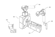
- FIG. 6 schematically illustrates an exemplary embodiment of the device with a combination of different imaging systems and multiple radiation pulse arms; in particular with one MRI imaging system, one x-ray imaging system, and two radiation pulse arms.
- the radiation pulse arm 602 is implemented into the MRI imaging system 601 .
- the radiation pulse arm 603 is stand-alone and pointing toward the patient, that is laying on the treatment bed 604 .
- the x-ray source 605 is pointed toward the patient and the x-ray detector 606 collects the x-ray passing through the patient.
- the MRI imaging system 601 is capable of imaging the target region with a time resolution better than 200 ms.
- the radiation pulse arm implemented into the MRI 602 is a laser plasma electron accelerator emitting neutral radiation.
- the radiation pulse arm 603 can be mounted on a static support, on a mechanically movable support, on a robotic arm, or on a gantry.
- the MRI imaging system 601 , the radiation pulse arm 602 , the radiation pulse arm 603 and the x-ray imaging system 605 are synchronized by a common synchronization system with a time resolution better than 200 ms.
- the treatment bed 604 may have an x-ray sensor incorporated.
- the treatment bed 604 can move along at least one direction.
- the x-ray detector 606 can be set to perform x-ray absorption imaging, x-ray fluoroscopy imaging or x-ray phase contrast imaging.
- FIG. 7 shows a 2-D plot describing the dose deposited inside a 10x20 cm water phantom by one of the possible beams emitted by the pulsed radiation source described in this patent application.
- it shows a beam containing 80 pC of electrons with 100 MeV kinetic energy.
- a single radiation pulse of this kind can deposit a dose higher than 50 mGy at a depth of at least 1 cm in water.
Landscapes
- Health & Medical Sciences (AREA)
- Engineering & Computer Science (AREA)
- Biomedical Technology (AREA)
- Pathology (AREA)
- Nuclear Medicine, Radiotherapy & Molecular Imaging (AREA)
- Radiology & Medical Imaging (AREA)
- Life Sciences & Earth Sciences (AREA)
- Animal Behavior & Ethology (AREA)
- General Health & Medical Sciences (AREA)
- Public Health (AREA)
- Veterinary Medicine (AREA)
- Radiation-Therapy Devices (AREA)
Abstract
La présente invention se rapporte à un système de radiothérapie qui comprend au moins une source de rayonnement pulsé, au minimum un système d'imagerie, un système de commande, et un système de synchronisation. La source de rayonnement pulsé dépose des impulsions de rayonnement à dose élevée sur une région cible à l'intérieur du patient, et, simultanément, le système d'imagerie sert à surveiller la région cible, avec une synchronisation par le système de synchronisation. La dose par impulsion de rayonnement est suffisamment élevée pour déposer, en peu d'impulsions, 1 Gy à une profondeur d'au moins 1 cm dans l'eau. À chaque étape du temps d'irradiation, ladite source de rayonnement pulsé délivre des impulsions de rayonnement courtes (< 1 ms) et ledit système d'imagerie réalise un instantané de la position, et finalement de la forme, de la région cible durant le temps d'irradiation, avec une résolution temporelle supérieure à 200 ms. Puisque la source de rayonnement pulsé et le système d'imagerie sont tous les deux synchronisés par le système de synchronisation avec une gigue inférieure à 200 ms, ce système permet une reconstruction très précise de la carte de la dose déposée dans la région cible.
Priority Applications (2)
| Application Number | Priority Date | Filing Date | Title |
|---|---|---|---|
| US16/309,668 US10603514B2 (en) | 2016-06-10 | 2017-06-09 | Device and method for high dose per pulse radiotherapy with real time imaging |
| EP17742938.8A EP3468666B1 (fr) | 2016-06-10 | 2017-06-09 | Dispositif et procédé pour une radiothérapie par impulsions à dose élevée avec une imagerie en temps réel |
Applications Claiming Priority (2)
| Application Number | Priority Date | Filing Date | Title |
|---|---|---|---|
| LU93102 | 2016-06-10 | ||
| LU93102A LU93102B1 (fr) | 2016-06-10 | 2016-06-10 | Dispositif et procédé pour une radiothérapie par impulsion à dose élevée avec une imagerie à temps réel |
Publications (1)
| Publication Number | Publication Date |
|---|---|
| WO2017211331A1 true WO2017211331A1 (fr) | 2017-12-14 |
Family
ID=56137486
Family Applications (1)
| Application Number | Title | Priority Date | Filing Date |
|---|---|---|---|
| PCT/CZ2017/050023 Ceased WO2017211331A1 (fr) | 2016-06-10 | 2017-06-09 | Dispositif et procédé pour une radiothérapie par impulsions à dose élevée avec une imagerie en temps réel |
Country Status (4)
| Country | Link |
|---|---|
| US (1) | US10603514B2 (fr) |
| EP (1) | EP3468666B1 (fr) |
| LU (1) | LU93102B1 (fr) |
| WO (1) | WO2017211331A1 (fr) |
Cited By (5)
| Publication number | Priority date | Publication date | Assignee | Title |
|---|---|---|---|---|
| CN109975859A (zh) * | 2019-05-06 | 2019-07-05 | 中国工程物理研究院激光聚变研究中心 | 一种高时空分辨软x射线辐射流定量测量系统 |
| US11013100B2 (en) | 2016-10-10 | 2021-05-18 | University Of Strathclyde | Plasma accelerator |
| CN114466500A (zh) * | 2020-11-10 | 2022-05-10 | 西门子医疗有限公司 | 闭环控制借助于直线加速器系统生成的x射线脉冲链 |
| WO2023047608A1 (fr) * | 2021-09-22 | 2023-03-30 | 雄二 古久保 | Dispositif de bnct robotisé et son procédé de fonctionnement |
| US12377291B2 (en) | 2020-05-12 | 2025-08-05 | Elekta Limited | Light detection apparatus and methods for a radiotherapy system |
Families Citing this family (27)
| Publication number | Priority date | Publication date | Assignee | Title |
|---|---|---|---|---|
| US11918831B2 (en) * | 2010-04-16 | 2024-03-05 | Susan L. Michaud | Hybrid bragg/flash proton therapy apparatus and method of use thereof |
| US11925818B2 (en) * | 2010-04-16 | 2024-03-12 | Susan L. Michaud | Flash proton therapy apparatus and method of use thereof |
| US9855445B2 (en) | 2016-04-01 | 2018-01-02 | Varian Medical Systems, Inc. | Radiation therapy systems and methods for delivering doses to a target volume |
| US11712579B2 (en) | 2017-07-21 | 2023-08-01 | Varian Medical Systems, Inc. | Range compensators for radiation therapy |
| US10549117B2 (en) | 2017-07-21 | 2020-02-04 | Varian Medical Systems, Inc | Geometric aspects of radiation therapy planning and treatment |
| US10843011B2 (en) | 2017-07-21 | 2020-11-24 | Varian Medical Systems, Inc. | Particle beam gun control systems and methods |
| US10183179B1 (en) | 2017-07-21 | 2019-01-22 | Varian Medical Systems, Inc. | Triggered treatment systems and methods |
| US11590364B2 (en) | 2017-07-21 | 2023-02-28 | Varian Medical Systems International Ag | Material inserts for radiation therapy |
| EP3654976A1 (fr) | 2017-07-21 | 2020-05-27 | Varian Medical Systems, Inc. | Procédés d'utilisation de rayonnement à débit de dose ultra élevé et d'agents thérapeutiques |
| US10092774B1 (en) | 2017-07-21 | 2018-10-09 | Varian Medical Systems International, AG | Dose aspects of radiation therapy planning and treatment |
| EP3710111B1 (fr) | 2017-11-16 | 2021-12-29 | Varian Medical Systems, Inc. | Sortie de faisceau améliorée et mise en forme de champ dynamique destinés à un système de radiothérapie |
| US10910188B2 (en) | 2018-07-25 | 2021-02-02 | Varian Medical Systems, Inc. | Radiation anode target systems and methods |
| US10814144B2 (en) | 2019-03-06 | 2020-10-27 | Varian Medical Systems, Inc. | Radiation treatment based on dose rate |
| US11116995B2 (en) | 2019-03-06 | 2021-09-14 | Varian Medical Systems, Inc. | Radiation treatment planning based on dose rate |
| US11103727B2 (en) | 2019-03-08 | 2021-08-31 | Varian Medical Systems International Ag | Model based PBS optimization for flash therapy treatment planning and oncology information system |
| US11090508B2 (en) | 2019-03-08 | 2021-08-17 | Varian Medical Systems Particle Therapy Gmbh & Co. Kg | System and method for biological treatment planning and decision support |
| IL265914B (en) * | 2019-04-08 | 2020-11-30 | Convergent R N R Ltd | System and method for optimization of radiotherapy treatments |
| US10918886B2 (en) | 2019-06-10 | 2021-02-16 | Varian Medical Systems, Inc. | Flash therapy treatment planning and oncology information system having dose rate prescription and dose rate mapping |
| US11291859B2 (en) | 2019-10-03 | 2022-04-05 | Varian Medical Systems, Inc. | Radiation treatment planning for delivering high dose rates to spots in a target |
| CN111103062B (zh) * | 2019-12-06 | 2021-02-12 | 太原理工大学 | 一种基于单光子计数二维成像的装置及方法 |
| EP4078607A1 (fr) * | 2019-12-20 | 2022-10-26 | Elekta AB (PUBL) | Algorithme d'accumulation de dose adaptative |
| US12390662B2 (en) | 2020-04-02 | 2025-08-19 | Siemens Healthineers International Ag | System and method for proton therapy treatment planning with proton energy and spot optimization |
| US11865361B2 (en) | 2020-04-03 | 2024-01-09 | Varian Medical Systems, Inc. | System and method for scanning pattern optimization for flash therapy treatment planning |
| US11541252B2 (en) | 2020-06-23 | 2023-01-03 | Varian Medical Systems, Inc. | Defining dose rate for pencil beam scanning |
| US11957934B2 (en) | 2020-07-01 | 2024-04-16 | Siemens Healthineers International Ag | Methods and systems using modeling of crystalline materials for spot placement for radiation therapy |
| US12064645B2 (en) | 2020-07-02 | 2024-08-20 | Siemens Healthineers International Ag | Methods and systems used for planning radiation treatment |
| JP7616867B2 (ja) * | 2020-11-13 | 2025-01-17 | キヤノンメディカルシステムズ株式会社 | 放射線治療装置及び方法 |
Citations (5)
| Publication number | Priority date | Publication date | Assignee | Title |
|---|---|---|---|---|
| US8039819B2 (en) | 2005-07-20 | 2011-10-18 | Ecole Polytechnique | Device and method for creating a spatial dose distribution in a medium volume |
| US20120294423A1 (en) * | 2010-10-01 | 2012-11-22 | Stephen Wah-Kwan Cheung | Systems and methods for cargo scanning and radiotherapy using a traveling wave linear accelerator based x-ray source using pulse width to modulate pulse-to-pulse dosage |
| US20150124930A1 (en) * | 2013-11-07 | 2015-05-07 | Varian Medical Systems International Ag | Time-resolved pre-treatment portal dosimetry systems, devices, and methods |
| US9044604B2 (en) | 2010-12-07 | 2015-06-02 | Siemens Aktiengesellschaft | Radiotherapy system |
| US20150157879A1 (en) * | 2013-12-09 | 2015-06-11 | University Of Miami | Radiation therapy device for ocular melanoma |
Family Cites Families (4)
| Publication number | Priority date | Publication date | Assignee | Title |
|---|---|---|---|---|
| SE0301508D0 (sv) * | 2003-05-23 | 2003-05-23 | Goergen Nilsson | Method for pre treatment verification in intensity modulates radiation therapy |
| US10940332B2 (en) * | 2011-05-19 | 2021-03-09 | The Trustees Of Dartmouth College | Cherenkov imaging systems and methods to monitor beam profiles and radiation dose while avoiding interference from room lighting |
| US8798234B2 (en) * | 2012-03-30 | 2014-08-05 | Elekta Ab (Publ) | Imaging during radiotherapy |
| US20170252579A1 (en) * | 2016-03-01 | 2017-09-07 | Accuray Incorporated | Linear accelerator with cerenkov emission detector |
-
2016
- 2016-06-10 LU LU93102A patent/LU93102B1/fr active IP Right Grant
-
2017
- 2017-06-09 EP EP17742938.8A patent/EP3468666B1/fr active Active
- 2017-06-09 US US16/309,668 patent/US10603514B2/en active Active
- 2017-06-09 WO PCT/CZ2017/050023 patent/WO2017211331A1/fr not_active Ceased
Patent Citations (5)
| Publication number | Priority date | Publication date | Assignee | Title |
|---|---|---|---|---|
| US8039819B2 (en) | 2005-07-20 | 2011-10-18 | Ecole Polytechnique | Device and method for creating a spatial dose distribution in a medium volume |
| US20120294423A1 (en) * | 2010-10-01 | 2012-11-22 | Stephen Wah-Kwan Cheung | Systems and methods for cargo scanning and radiotherapy using a traveling wave linear accelerator based x-ray source using pulse width to modulate pulse-to-pulse dosage |
| US9044604B2 (en) | 2010-12-07 | 2015-06-02 | Siemens Aktiengesellschaft | Radiotherapy system |
| US20150124930A1 (en) * | 2013-11-07 | 2015-05-07 | Varian Medical Systems International Ag | Time-resolved pre-treatment portal dosimetry systems, devices, and methods |
| US20150157879A1 (en) * | 2013-12-09 | 2015-06-11 | University Of Miami | Radiation therapy device for ocular melanoma |
Non-Patent Citations (2)
| Title |
|---|
| LE GARREC BRUNO ET AL: "ELI-beamlines: extreme light infrastructure science and technology with ultra-intense lasers", OPTOMECHATRONIC MICRO/NANO DEVICES AND COMPONENTS III : 8 - 10 OCTOBER 2007, LAUSANNE, SWITZERLAND; [PROCEEDINGS OF SPIE , ISSN 0277-786X], SPIE, BELLINGHAM, WASH, vol. 8962, 25 February 2014 (2014-02-25), pages 89620I - 89620I, XP060034292, ISBN: 978-1-62841-730-2, DOI: 10.1117/12.2039165 * |
| S. FARSIU ET AL.: "Statistical detection and imaging of objects hidden in turbid media using ballistic photons", APPLIED OPTICS, vol. 46, no. 23, 2007, XP001506962, DOI: doi:10.1364/AO.46.005805 |
Cited By (7)
| Publication number | Priority date | Publication date | Assignee | Title |
|---|---|---|---|---|
| US11013100B2 (en) | 2016-10-10 | 2021-05-18 | University Of Strathclyde | Plasma accelerator |
| CN109975859A (zh) * | 2019-05-06 | 2019-07-05 | 中国工程物理研究院激光聚变研究中心 | 一种高时空分辨软x射线辐射流定量测量系统 |
| CN109975859B (zh) * | 2019-05-06 | 2023-10-31 | 中国工程物理研究院激光聚变研究中心 | 一种高时空分辨软x射线辐射流定量测量系统 |
| US12377291B2 (en) | 2020-05-12 | 2025-08-05 | Elekta Limited | Light detection apparatus and methods for a radiotherapy system |
| CN114466500A (zh) * | 2020-11-10 | 2022-05-10 | 西门子医疗有限公司 | 闭环控制借助于直线加速器系统生成的x射线脉冲链 |
| CN114466500B (zh) * | 2020-11-10 | 2023-07-04 | 西门子医疗有限公司 | 闭环控制借助于直线加速器系统生成的x射线脉冲链 |
| WO2023047608A1 (fr) * | 2021-09-22 | 2023-03-30 | 雄二 古久保 | Dispositif de bnct robotisé et son procédé de fonctionnement |
Also Published As
| Publication number | Publication date |
|---|---|
| LU93102B1 (fr) | 2018-01-22 |
| EP3468666B1 (fr) | 2019-07-03 |
| US20190329071A1 (en) | 2019-10-31 |
| EP3468666A1 (fr) | 2019-04-17 |
| US10603514B2 (en) | 2020-03-31 |
Similar Documents
| Publication | Publication Date | Title |
|---|---|---|
| US10603514B2 (en) | Device and method for high dose per pulse radiotherapy with real time imaging | |
| US11712585B2 (en) | Systems, methods, and devices for high-energy irradiation | |
| US11114269B2 (en) | Bremsstrahlung target for radiation therapy system | |
| US20100108903A1 (en) | Determination of control parameters for irradiation of a moving target volume in a body | |
| WO2015169011A1 (fr) | Système de robot de radiothérapie à faisceau d'électrons ou à faisceau de photons d'extra-haute énergie | |
| US10039935B1 (en) | Systems and methods for providing an ion beam | |
| CN104053475A (zh) | 电荷粒子照射系统以及电荷粒子照射方法 | |
| IL270996A (en) | Systems and methods for ion beam satisfaction | |
| US10395881B2 (en) | Systems and methods for providing an ion beam | |
| JP2012254146A (ja) | 荷電粒子ビーム照射システム | |
| US20220117075A1 (en) | Systems and methods for compact laser wakefield accelerated electrons and x-rays | |
| JP6465283B2 (ja) | 放射線治療システム | |
| US20230126790A1 (en) | System and method for particle therapy | |
| Meier et al. | „Development of a setup for laser-Compton backscattering at the S-DALINAC “ | |
| JP2013138774A (ja) | 放射線治療システム | |
| KR101412611B1 (ko) | 이온 전리함 배열 검출기의 공간 분해능을 향상시키는 방사선 측정장치 및 방법 | |
| US11501943B2 (en) | Systems and methods for providing a beam of charged particles | |
| CN103007438B (zh) | 用于在粒子照射计划中确定照射持续时间的方法和装置 | |
| HK40072793A (en) | Systems and methods for compact laser wakefield accelerated electrons and x-rays |
Legal Events
| Date | Code | Title | Description |
|---|---|---|---|
| 121 | Ep: the epo has been informed by wipo that ep was designated in this application |
Ref document number: 17742938 Country of ref document: EP Kind code of ref document: A1 |
|
| NENP | Non-entry into the national phase |
Ref country code: DE |
|
| ENP | Entry into the national phase |
Ref document number: 2017742938 Country of ref document: EP Effective date: 20190110 |