WO2017213027A1 - 作業機械 - Google Patents
作業機械 Download PDFInfo
- Publication number
- WO2017213027A1 WO2017213027A1 PCT/JP2017/020523 JP2017020523W WO2017213027A1 WO 2017213027 A1 WO2017213027 A1 WO 2017213027A1 JP 2017020523 W JP2017020523 W JP 2017020523W WO 2017213027 A1 WO2017213027 A1 WO 2017213027A1
- Authority
- WO
- WIPO (PCT)
- Prior art keywords
- current
- electromagnetic valve
- operation member
- intention
- determination unit
- Prior art date
- Legal status (The legal status is an assumption and is not a legal conclusion. Google has not performed a legal analysis and makes no representation as to the accuracy of the status listed.)
- Ceased
Links
Images




Classifications
-
- G—PHYSICS
- G05—CONTROLLING; REGULATING
- G05D—SYSTEMS FOR CONTROLLING OR REGULATING NON-ELECTRIC VARIABLES
- G05D16/00—Control of fluid pressure
- G05D16/04—Control of fluid pressure without auxiliary power
- G05D16/06—Control of fluid pressure without auxiliary power the sensing element being a flexible membrane, yielding to pressure, e.g. diaphragm, bellows, capsule
- G05D16/08—Control of liquid pressure
-
- E—FIXED CONSTRUCTIONS
- E02—HYDRAULIC ENGINEERING; FOUNDATIONS; SOIL SHIFTING
- E02F—DREDGING; SOIL-SHIFTING
- E02F9/00—Component parts of dredgers or soil-shifting machines, not restricted to one of the kinds covered by groups E02F3/00 - E02F7/00
- E02F9/20—Drives; Control devices
- E02F9/2004—Control mechanisms, e.g. control levers
-
- E—FIXED CONSTRUCTIONS
- E02—HYDRAULIC ENGINEERING; FOUNDATIONS; SOIL SHIFTING
- E02F—DREDGING; SOIL-SHIFTING
- E02F9/00—Component parts of dredgers or soil-shifting machines, not restricted to one of the kinds covered by groups E02F3/00 - E02F7/00
- E02F9/20—Drives; Control devices
- E02F9/2025—Particular purposes of control systems not otherwise provided for
-
- E—FIXED CONSTRUCTIONS
- E02—HYDRAULIC ENGINEERING; FOUNDATIONS; SOIL SHIFTING
- E02F—DREDGING; SOIL-SHIFTING
- E02F9/00—Component parts of dredgers or soil-shifting machines, not restricted to one of the kinds covered by groups E02F3/00 - E02F7/00
- E02F9/20—Drives; Control devices
-
- E—FIXED CONSTRUCTIONS
- E02—HYDRAULIC ENGINEERING; FOUNDATIONS; SOIL SHIFTING
- E02F—DREDGING; SOIL-SHIFTING
- E02F9/00—Component parts of dredgers or soil-shifting machines, not restricted to one of the kinds covered by groups E02F3/00 - E02F7/00
- E02F9/20—Drives; Control devices
- E02F9/22—Hydraulic or pneumatic drives
- E02F9/2221—Control of flow rate; Load sensing arrangements
-
- E—FIXED CONSTRUCTIONS
- E02—HYDRAULIC ENGINEERING; FOUNDATIONS; SOIL SHIFTING
- E02F—DREDGING; SOIL-SHIFTING
- E02F9/00—Component parts of dredgers or soil-shifting machines, not restricted to one of the kinds covered by groups E02F3/00 - E02F7/00
- E02F9/20—Drives; Control devices
- E02F9/22—Hydraulic or pneumatic drives
- E02F9/2264—Arrangements or adaptations of elements for hydraulic drives
- E02F9/2267—Valves or distributors
-
- F—MECHANICAL ENGINEERING; LIGHTING; HEATING; WEAPONS; BLASTING
- F15—FLUID-PRESSURE ACTUATORS; HYDRAULICS OR PNEUMATICS IN GENERAL
- F15B—SYSTEMS ACTING BY MEANS OF FLUIDS IN GENERAL; FLUID-PRESSURE ACTUATORS, e.g. SERVOMOTORS; DETAILS OF FLUID-PRESSURE SYSTEMS, NOT OTHERWISE PROVIDED FOR
- F15B11/00—Servomotor systems without provision for follow-up action; Circuits therefor
- F15B11/08—Servomotor systems without provision for follow-up action; Circuits therefor with only one servomotor
-
- F—MECHANICAL ENGINEERING; LIGHTING; HEATING; WEAPONS; BLASTING
- F16—ENGINEERING ELEMENTS AND UNITS; GENERAL MEASURES FOR PRODUCING AND MAINTAINING EFFECTIVE FUNCTIONING OF MACHINES OR INSTALLATIONS; THERMAL INSULATION IN GENERAL
- F16K—VALVES; TAPS; COCKS; ACTUATING-FLOATS; DEVICES FOR VENTING OR AERATING
- F16K13/00—Other constructional types of cut-off apparatus; Arrangements for cutting-off
- F16K13/08—Arrangements for cutting-off not used
- F16K13/10—Arrangements for cutting-off not used by means of liquid or granular medium
Definitions
- the present invention relates to a work machine.
- the neutral position detection means for detecting the neutral position of the operation lever, and the transmission of the signal between the control body of the control means and the control valve when the output signal of the neutral position detection means is input and the operation lever is in the neutral position.
- a drive control device for a hydraulic machine provided with a prohibiting means for prohibiting (see Patent Document 1). According to the drive control device described in Patent Document 1, even if an electric signal including a control main body of the control means is broken down or mixed with noise due to work and an error signal is generated, the error signal is generated in the control valve. Without being transmitted, the control valve can be returned to the neutral position.
- a work machine includes a hydraulic pump, a hydraulic actuator driven by pressure oil discharged from the hydraulic pump, and an electromagnetic that controls a flow of pressure oil supplied from the hydraulic pump to the hydraulic actuator.
- a work machine comprising: a valve device; an operation member that operates the electromagnetic valve device; and an operation position determination unit that determines whether the operation member is disposed within a preset neutral range.
- An operation intention determination unit that determines whether or not the operator intends to operate the operation member based on a change in the state of the member, and supplies current to the electromagnetic valve device based on the operation of the operation member
- the operation position determination unit determines that the operation member is disposed within a neutral range, and the operation intention determination unit determines the operation.
- the responsiveness of the electromagnetic valve device to the operation can be improved.
- the side view of a hydraulic excavator The figure which shows schematic structure of the hydraulic shovel which concerns on the 1st Embodiment of this invention.
- (A) is a figure explaining operation
- (b) is a figure explaining the neutral range of an operation lever.
- the block diagram which shows the structure of the controller which concerns on the 1st Embodiment of this invention.
- (A) is a figure which shows the relationship between the operating angle (theta) of an operating lever, and the target value (refer solid line) of the control current output to a 1st solenoid valve
- (b) is the operating angle (theta) of an operating lever, and a 2nd solenoid valve
- the figure which shows the relationship with the target value (refer a continuous line) of the control current to output.
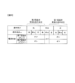
- the figure explaining the conditions for determining whether an electric current is supplied to a solenoid valve.
- the flowchart which shows an example of the process by the solenoid valve control program performed by the controller which concerns on the 1st Embodiment of this invention.
- (A) is a time chart which shows operation
- (b) is a time chart which shows operation
- (A) is a time chart which shows operation
- (b) is a time chart which shows operation
- the block diagram which shows the structure of the controller which concerns on the 2nd Embodiment of this invention.
- the flowchart which shows an example of the process by the solenoid valve control program performed by the controller which concerns on the 2nd Embodiment of this invention.
- FIG. 1 is a side view of a hydraulic excavator (backhoe) 100 which is an example of a work machine.
- a hydraulic excavator 100 includes a traveling body 101 and a revolving body 102 that is turnably mounted on the traveling body 101.
- the traveling body 101 travels by driving a pair of left and right crawlers by a traveling motor.
- a driver's cab 107 is provided on the left side of the front part of the swivel body 102, and an engine room is provided at the rear of the driver's cab 107.
- the engine room houses an engine, hydraulic equipment, and the like that are power sources.
- a counterweight 109 for balancing the airframe during work is attached to the rear of the engine compartment.
- a front working device 103 is provided on the right side of the front portion of the swivel body 102.
- the front working device 103 includes a plurality of front members, that is, a boom 104, an arm 105, and a bucket 106.
- the boom 104 is pivotally attached to the front part of the swing body 102 at the base end.
- One end of the arm 105 is rotatably attached to the tip of the boom 104.
- the boom 104 and the arm 105 are driven to rotate by the boom cylinder 104a and the arm cylinder 105a, respectively.
- the bucket 106 is attached at the tip of the arm 105 so as to be rotatable in the vertical direction with respect to the arm 105, and is driven to rotate by the bucket cylinder 106a.
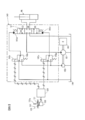
- FIG. 2 is a diagram showing a schematic configuration of the hydraulic excavator 100 according to the first embodiment of the present invention.
- the hydraulic circuit included in the excavator 100 controls a plurality of hydraulic actuators such as a boom cylinder 104a, an arm cylinder 105a, a bucket cylinder 106a, a turning hydraulic motor, and a flow of pressure oil supplied to these hydraulic actuators.
- a solenoid valve device or the like is provided.
- one hydraulic actuator HA for example, bucket cylinder 106a
- FIG. 2 corresponds to a diagram showing a configuration for driving one hydraulic actuator (for example, bucket cylinder 106a).
- the hydraulic excavator 100 includes a controller 120, an engine 190, a main pump 151, a pilot pump 152, a solenoid valve device 140, and an operation device 130.
- the controller 120 includes an arithmetic processing unit having a CPU and a storage device such as ROM and RAM, and other peripheral circuits, and controls each part of the excavator 100.
- An operation amount sensor 133 is connected to the controller 120.
- the operation amount sensor 133 detects the rotation angle of the operation lever 131 of the operation device 130 as an operation angle (operation amount) ⁇ , and outputs a signal corresponding to the operation angle ⁇ to the controller 120.
- the operation amount sensor 133 for example, a potentiometer that outputs a voltage corresponding to the rotation angle of the operation lever 131 can be configured.
- the electric operation device 130 operates an electromagnetic valve device 140 described later, and includes an operation lever 131, an operation amount sensor 133, and a return mechanism including a return spring 132.
- the operating lever 131 is a rotatable rod-shaped member, and a grip portion 131a that is gripped by the operator is provided at the tip.
- a return spring 132 is connected to the operation lever 131, and the operation lever 131 is elastically biased toward the neutral position by the return spring 132.
- the return mechanism also has a function as a reaction force application device that applies an operation reaction force to the operation lever 131.
- a plurality of operating devices 130 are disposed in the cab 107.
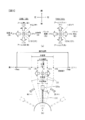
- FIG. 3A is a view for explaining the operation of the excavator 100 corresponding to the operation direction of the operation lever 131.
- the operating device 130 a right operating device 130A located on the right side of the driver's seat and a left operating device 130B located on the left side of the driver's seat are provided.
- FIG. 3B is a diagram for explaining the neutral range of the operation lever 131.
- the neutral position (NP) of the operation lever 131 is set to a position that divides the rotation range of the operation lever 131 into two.
- the operation angle ⁇ of the operation lever 131 corresponds to an inclination angle from the neutral position (NP).
- the operation angle ⁇ when the operation lever 131 is located at the neutral position (NP) is set to 0 °.
- the operation angle ⁇ increases in the positive direction when tilted to one side from the neutral position (NP). Further, when the operation angle ⁇ is tilted from the neutral position (NP) to the other side, the operation angle ⁇ increases in the negative direction, that is, becomes smaller than 0 °.
- the right operation device 130A is an operation device that operates the rotation operation of the boom 104 with respect to the revolving structure 102 and the rotation operation of the bucket 106 with respect to the arm 105.
- the operating lever hereinafter referred to as the right operating lever 131A
- the boom lowering operation is an operation in which the boom cylinder 104a contracts and the boom 104 rotates downward at a speed corresponding to the operation angle ( ⁇ 1).
- the right operation lever 131A is tilted rearward from the neutral position (NP)
- the negative operation angle ( ⁇ 1) is decreased, and the boom raising operation is performed.
- the boom raising operation is an operation in which the boom cylinder 104a extends and the boom 104 rotates upward at a speed corresponding to the operation angle ( ⁇ 1).
- a bucket earthing operation (also called a bucket dump operation) is performed.
- the bucket earthing operation means that the bucket 106 rotates at a speed corresponding to the operation angle ( ⁇ 2) so that the bucket cylinder 106a contracts and the toe (tip) of the bucket 106 moves away from the abdominal surface of the arm 105 (FIG. 1). (Clockwise rotation).
- the negative operation angle ( ⁇ 2) decreases, and a bucket excavation operation (also referred to as a bucket cloud operation) is performed.
- the bucket excavation operation means that the bucket 106 rotates at a speed corresponding to the operation angle ( ⁇ 2) so that the bucket cylinder 106a extends and the tip of the bucket 106 approaches the abdominal surface of the arm 105 (in FIG. 1). (Rotating counterclockwise).
- the operation lever (hereinafter referred to as the left operation lever 131B) of the left operation device 130B is an operation member that operates the rotation operation of the arm 105 relative to the boom 104 and the rotation operation of the revolving structure 102.
- the left operation lever 131B is tilted forward from the neutral position (NP)
- the positive operation angle ( ⁇ 3) is increased
- an arm pushing operation also referred to as an arm extending operation
- the arm pushing operation means that the arm cylinder 105a contracts and the arm 105 rotates at a speed corresponding to the operation angle ( ⁇ 3) in the direction in which the relative angle of the arm 105 expands with respect to the boom 104 (clockwise in FIG. 1). To rotate).
- the arm pulling operation means that the arm 105 rotates at a speed corresponding to the operation angle ( ⁇ 3) so that the arm cylinder 105a extends and the arm 105 is folded to the boom 104 side (rotates counterclockwise in FIG. 1). Is) operation.
- the dead zone is an operation area where the hydraulic actuator HA corresponding to the operation lever 131 does not operate, and the hydraulic pressure is sharply increased only when the operation lever 131 is slightly tilted from the neutral position (NP). It is provided to prevent the actuator HA from being driven.
- the dead zone is set in a range where the operation angle is ( ⁇ d) or more and (+ ⁇ d) or less, for example, about 15 to 25% of the entire operation range. Note that ⁇ d is a positive number ( ⁇ d> 0).
- the neutral range is an operation region set in advance in the dead zone, and is provided for use in determining whether or not to supply a control current to the solenoid valve device 140.
- the neutral range is set such that the operation angle is not less than ( ⁇ n) and not more than (+ ⁇ n), and is, for example, about 5 to 10% of the entire operation range.
- ⁇ n is a positive number smaller than ⁇ d and is an angle threshold value representing the boundary of the neutral range ( ⁇ n ⁇ d).
- the first angle threshold (+ ⁇ n), which is a positive angle threshold, and the second angle threshold ( ⁇ n), which is a negative angle threshold, are stored in advance in the storage device of the controller 120.
- the controller 120 receives signals corresponding to the operation angles ⁇ ( ⁇ 1, ⁇ 2, ⁇ 3, ⁇ 4) of the left operation lever 131B and the right operation lever 131A.
- the controller 120 detects the operation direction and the operation angle of the left operation lever 131B and the right operation lever 131A based on the operation angle ⁇ signal from the operation amount sensor 133.
- the main pump 151 and the pilot pump 152 which are hydraulic pumps, are driven by the engine 190 and discharge the hydraulic oil in the tank 199 as pressure oil.
- the hydraulic actuator HA is driven by pressure oil discharged from the main pump 151.
- the electromagnetic valve device 140 includes a hydraulic pilot type directional control valve 141 that controls the flow of pressure oil supplied from the main pump 151 to the hydraulic actuator HA, and two electromagnetic proportional pressure reducing valves that control the operation of the directional control valve 141 ( Hereinafter, the first electromagnetic valve 142p and the second electromagnetic valve 142m) are provided.
- the first solenoid valve 142p is connected to the pilot pump 152, and generates a pilot pressure to be supplied to the first pilot portion 141p of the direction control valve 141 when the operation lever 131 is rotated to the positive side outside the neutral range.
- the second electromagnetic valve 142m is connected to the pilot pump 152, and generates a pilot pressure to be supplied to the second pilot portion 141m of the direction control valve 141 when the operation lever 131 is turned to the negative side outside the neutral range. To do.
- the hydraulic actuator HA in FIG. 2 is described as a bucket cylinder 106a, and the driving of the bucket 106 will be representatively described.
- the controller 120 outputs a control current (excitation current) to the solenoids 143p and 143m of the electromagnetic valves 142p and 142m according to the operation direction and operation angle of the operation lever 131.
- the degree of pressure reduction of the first electromagnetic valve 142p is set by the control current supplied from the controller 120 according to the operation angle ( ⁇ ).
- the degree of pressure reduction of the second electromagnetic valve 142m is set by the control current supplied from the controller 120 according to the operation angle ( ⁇ ).
- the opening characteristics of the solenoid valves 142p and 142m are such that the degree of pressure reduction decreases with increasing control current input to the solenoids 143p and 143m, that is, the secondary pressure (pilot pressure) increases with increasing control current. Is set to
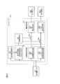
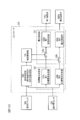
- FIG. 4 is a block diagram showing the configuration of the controller 120 according to the first embodiment of the present invention.
- the controller 120 includes a target current determination unit 122, a current supply unit 123, an operation speed calculation unit 127, a condition determination unit 128, and a current control unit 129.
- a power supply device (not shown) is connected to the controller 120.
- the current supply unit 123 includes a first current supply unit 123a that supplies current to the solenoid 143p of the first electromagnetic valve 142p that constitutes the electromagnetic valve device 140 when the operation lever 131 is rotated to the positive side. .
- the current supply unit 123 includes a second current supply unit 123b that supplies a current to the solenoid 143m of the second electromagnetic valve 142m constituting the electromagnetic valve device 140 when the operation lever 131 is turned to the negative side. .
- the current supply unit 123 adjusts the magnitude of the control current based on the target value of the control current set by the target current determination unit 122, which will be described later, and supplies the control current to each solenoid 143p, 143m.
- the current supply unit 123 does not supply current to the electromagnetic valves 142p and 142m.
- the target current determination unit 122 is a target value of the control current supplied from the current supply unit 123 to the solenoids 143p and 143m of the electromagnetic valves 142p and 142m based on the operation angle ⁇ of the operation lever 131 detected by the operation amount sensor 133. To decide.
- the target current determination unit 122 includes a first target current determination unit 122a and a second target current determination unit 122b.
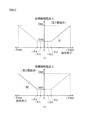
- FIG. 5A is a diagram showing the relationship between the operating angle ⁇ of the operating lever 131 and the target value (see solid line) of the control current output to the first electromagnetic valve 142p
- FIG. It is a figure which shows the relationship between the operation angle (theta) and the target value (refer solid line) of the control current output to the 2nd solenoid valve 142m.
- a characteristic N1 shown in FIG. 5A and a characteristic N2 shown in FIG. 5B are stored in a lookup table format.
- the first target current determination unit 122a refers to the table of the characteristic N1 indicated by the solid line in FIG. 5A, and based on the operation angle ⁇ detected by the operation amount sensor 133, moves to the solenoid 143p of the first electromagnetic valve 142p.
- a target value (target control current It) of the control current to be output is set.
- the target control current It is set to the minimum current Imin.
- the target control current It increases linearly as the operation angle ⁇ increases.
- the target control current It is set to the maximum current Imax.
- the second target current determination unit 122b refers to the table of the characteristic N2 indicated by the solid line in FIG. 5B, and based on the operation angle ⁇ detected by the operation amount sensor 133, the second electromagnetic valve 142m A target value (target control current It) of the control current output to the solenoid 143m is set.
- the target control current It is set to the minimum current Imin.
- the operation angle ⁇ decreases, that is, the absolute value
- the target control current It is set to the maximum current Imax.
- the maximum current Imax is a target value for minimizing the degree of pressure reduction of the solenoid valves 142p, 142m.
- the minimum current Imin is a target value for causing the electromagnetic valve device 140 to supply a standby current when the operation lever 131 is disposed within the neutral range.
- the minimum current Imin is also referred to as a standby current Imin.
- the standby current Imin is a very small current of about 10 mA to 400 mA, for example, and is lower than the current when the hydraulic actuator HA starts driving, in other words, lower than the current when the spool of the directional control valve 141 starts operation. is there.
- the standby current is dithered at a predetermined frequency in the current supply unit 123. For this reason, when a standby current is supplied to the solenoids 143p and 143m of the electromagnetic valves 142p and 142m, the spools of the electromagnetic valves 142p and 142m vibrate slightly, thereby reducing the friction of the sliding portion and making it easy to start. Become.
- the operation speed calculation unit 127 calculates an operation speed (angular velocity) ⁇ of the operation lever 131 based on the operation angle ⁇ of the operation lever 131 detected by the operation amount sensor 133.
- the operation speed calculator 127 repeatedly calculates the operation speed ⁇ every predetermined control period (for example, about 1 ms to 10 ms).
- ( ⁇ ⁇ / ⁇ t)
- the operation speed calculation unit 127 calculates the operation speed ⁇ that is the time change rate of the operation angle ⁇ by differentiating the operation angle ⁇ with respect to time.
- the condition determination unit 128 determines whether the first electromagnetic valve validation condition is satisfied, and It is determined whether the second electromagnetic valve validation condition is satisfied.
- FIG. 6 is a diagram for explaining conditions for determining whether or not to supply current to the electromagnetic valves 142p and 142m.
- the condition determination unit 128 is an operation intention determination unit that determines whether the operator intends to operate the operation lever 131 based on the operation speed ⁇ that is the time change rate of the operation angle ⁇ of the operation lever 131.
- condition determination unit 128 has a function as an operation position determination unit that determines whether the operation lever 131 is disposed within a preset neutral range based on the operation angle ⁇ of the operation lever 131. ing.
- condition determination unit 128 will be described in detail.
- the condition determination unit 128 determines that the first electromagnetic valve activation condition is satisfied when the use of the first electromagnetic valve 142p is specified when the operation lever 131 is disposed on the positive side outside the neutral range.
- the condition determination unit 128 determines that the operation lever 131 is disposed on the positive side outside the neutral range.
- the condition determination unit 128 When it is determined that the operation lever 131 is disposed within the neutral range and the operation lever 131 is intended to operate in the bucket discharging direction (positive side), the condition determination unit 128 Assuming that the use of 142p is estimated, it is determined that the first electromagnetic valve validation condition is satisfied. When the absolute value
- the condition determination unit 128 determines that the second electromagnetic valve activation condition is satisfied when the use of the second electromagnetic valve 142m is specified when the operation lever 131 is disposed on the negative side outside the neutral range.
- the condition determination unit 128 determines that the operation lever 131 is disposed on the negative side outside the neutral range.
- the condition determination unit 128 determines that the second electromagnetic valve 142m It is determined that the second electromagnetic valve validation condition is satisfied.
- the condition determination unit 128 determines that there is an intention to operate the operation lever 131 in the bucket excavation direction (negative side).
- the condition determination unit 128 activates the first solenoid valve and the second solenoid valve. It is determined that none of the conditions are satisfied.
- the condition determination unit 128 does not intend to operate the operation lever 131 when the operation speed ⁇ of the operation lever 131 is larger than the second speed threshold ( ⁇ i) and smaller than the first speed threshold (+ ⁇ i). Is determined.
- the first speed threshold (+ ⁇ i), which is a positive speed threshold, and the second speed threshold ( ⁇ i), which is a negative speed threshold, are stored in advance in the storage device of the controller 120.
- ⁇ i is a positive number and is a speed threshold value for determining whether or not the operation lever 131 is stopped.
- ⁇ i is a value slightly larger than 0 ( ⁇ i> 0).
- the condition determination unit 128 determines that there is no intention to operate the operation lever 131 when the absolute value
- the current control unit 129 outputs an enabling signal to the first switch 126 a and outputs an invalidating signal to the second switch 126 b when the first solenoid valve enabling condition is satisfied.
- the first switch 126a permits a signal corresponding to the target control current It set by the first target current determination unit 122a to be supplied to the first current supply unit 123a.
- the second switch 126b prohibits a signal corresponding to the target control current It set by the second target current determination unit 122b from being supplied to the second current supply unit 123b.
- the current control unit 129 permits, that is, enables the control current to be supplied from the first current supply unit 123a to the first electromagnetic valve 142p that is estimated or specified to be used.
- the current control unit 129 prohibits, that is, invalidates the supply of the control current from the second current supply unit 123b to the second electromagnetic valve 142m that is not estimated or specified to be used.
- the current control unit 129 outputs an invalidation signal to the first switch 126 a and outputs an validation signal to the second switch 126 b when the second electromagnetic valve validation condition is satisfied.
- the second switch 126b permits a signal corresponding to the target control current It set by the second target current determination unit 122b to be supplied to the second current supply unit 123b.
- the first switch 126a prohibits a signal corresponding to the target control current It set by the first target current determination unit 122a from being supplied to the first current supply unit 123a.
- the current control unit 129 permits, that is, enables the control current to be supplied from the second current supply unit 123b to the second electromagnetic valve 142m that is estimated or specified to be used.
- the current control unit 129 prohibits, that is, invalidates the supply of the control current from the first current supply unit 123a to the first electromagnetic valve 142p that is not estimated or specified to be used.
- the current control unit 129 outputs an invalidation signal to each of the first switch 126a and the second switch 126b when neither the first solenoid valve validation condition nor the second solenoid valve validation condition is satisfied. Accordingly, the first switch 126a and the second switch 126b are prohibited from supplying a signal corresponding to the target control current It to each of the first current supply unit 123a and the second current supply unit 123b. That is, the current control unit 129 is supplied from the first current supply unit 123a and the second current supply unit 123b to each of the first electromagnetic valve 142p and the second electromagnetic valve 142m that are not estimated or specified to be used. Prohibit the supply of control current, ie disable it.
- the current is allowed to be supplied from the first current supply unit 123a to the first electromagnetic valve 142p (the first electromagnetic valve is on), and the second Supply of current from the current supply unit 123b to the second electromagnetic valve 142m is prohibited (second electromagnetic valve off).
- the second electromagnetic valve validation condition is satisfied, the current is prohibited from being supplied from the first current supply unit 123a to the first electromagnetic valve 142p (the first electromagnetic valve is off), and the second current supply unit 123b is set to the second state. Supply of current to the solenoid valve 142m is permitted (second solenoid valve on).
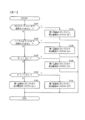
- FIG. 7 is a flowchart showing an example of processing by the solenoid valve control program executed by the controller 120 according to the first embodiment of the present invention.
- the process shown in the flowchart of FIG. 7 is started when an ignition switch (not shown) is turned on, and after initial settings (not shown), the processes after step S110 are performed every predetermined control period (for example, about 1 ms to 10 ms). Are repeatedly executed by the controller 120.
- the controller 120 acquires information on the operation angle ⁇ detected by the operation amount sensor 133 for each predetermined control cycle.
- the controller when the controller outputs an on signal to the solenoid valve, it means that the controller permits the current to be supplied to the solenoid valve, and when the controller outputs an off signal to the solenoid valve, the controller It means prohibiting the supply of current to the solenoid valve.
- step S110 the controller 120 calculates the operation speed ⁇ based on the operation angle ⁇ detected by the operation amount sensor 133, and proceeds to step S120.
- step S120 the controller 120 determines that the absolute value
- step S125 the controller 120 outputs an ON signal to the first electromagnetic valve 142p, outputs an OFF signal to the second electromagnetic valve 142m, and ends the process shown in the flowchart of FIG.
- step S130 the controller 120 determines that the absolute value
- step S135 the controller 120 outputs an off signal to the first electromagnetic valve 142p, outputs an on signal to the second electromagnetic valve 142m, and ends the processing shown in the flowchart of FIG.
- step S140 the controller 120 determines whether or not the operation angle ⁇ is smaller than the second angle threshold ( ⁇ n). If an affirmative determination is made in step S140, the process proceeds to step S145, and if a negative determination is made in step S140, the process proceeds to step S150.
- step S145 the controller 120 outputs an off signal to the first electromagnetic valve 142p, outputs an on signal to the second electromagnetic valve 142m, and ends the processing shown in the flowchart of FIG.
- step S150 the controller 120 determines whether or not the operation angle ⁇ is larger than the first angle threshold (+ ⁇ n). If an affirmative determination is made in step S150, the process proceeds to step S155, and if a negative determination is made in step S150, the process proceeds to step S160.
- step S155 the controller 120 outputs an ON signal to the first electromagnetic valve 142p, outputs an OFF signal to the second electromagnetic valve 142m, and ends the processing shown in the flowchart of FIG.
- step S160 the controller 120 outputs an off signal to the first electromagnetic valve 142p, outputs an off signal to the second electromagnetic valve 142m, and ends the processing shown in the flowchart of FIG.
- the glass swinging work refers to work that quickly shakes the bucket 106 to distribute earth and sand, concrete pieces, iron materials, and the like in the bucket 106.
- the dumping operation and the cloud operation are alternately repeated in the rattling operation.
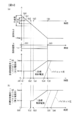
- FIG. 8A is a time chart showing the operation of the controller 120 according to the present embodiment
- FIG. 8B is a time chart showing the operation of the controller according to the comparative example.
- the horizontal axis in FIG. 8 indicates the elapsed time.
- the upper graph in FIG. 8A shows the time change of the operation angle ⁇
- the middle graph shows the time change of the operation speed ⁇
- the lower graph shows the time change of the target control current It with respect to the first electromagnetic valve 142p. Show.
- the lower graph of FIG. 8 (a) the change with time of the pilot pressure generated by the first electromagnetic valve 142p is also shown by a broken line.
- FIG. 8B is a diagram similar to the lower graph of FIG.
- the controller according to the comparative example prohibits the supply of the control current to the solenoid valve when the operation lever 131 is disposed within the neutral range regardless of the operation speed ⁇ . When it is arranged outside the neutral range, the control current is allowed to be supplied to the solenoid valve.
- the operator does not touch the operation lever 131, and the operation lever 131 is in a non-operation state.
- the operation speed ⁇ increases (time ta1).
- the operation speed ⁇ increases, the above-described first solenoid valve validation condition is satisfied (Yes in step S120), and therefore, the standby current Imin is supplied to the first solenoid valve 142p.
- the target control current It increases as the operating angle ⁇ increases (time ta3 to time ta5). Since the control current supplied to the first electromagnetic valve 142p increases, the pilot pressure increases from time ta4. When the operation lever 131 is operated up to the maximum operation angle (+ ⁇ max) at time ta5, the operation speed ⁇ becomes zero.
- the standby current Imin is not supplied to the first electromagnetic valve 142p while the operation lever 131 is located within the neutral range (time ta0 to time ta2).
- the standby current Imin is supplied to the first electromagnetic valve 142p when the operation lever 131 is positioned within the dead zone outside the neutral range (time ta2 to time ta3).
- the standby current Imin supply start timing (time point ta2) is later than in the present embodiment, and therefore the standby current application time is short.
- the pilot pressure increase start timing (time point ta6) is delayed as compared with the present embodiment.
- the operation lever 131 even when the operation lever 131 is positioned within the neutral range, it is determined that the operator intends to operate the operation lever 131 in the bucket discharging direction (positive direction).
- the first electromagnetic valve 142p is estimated to be used, and the standby current Imin is supplied to the first electromagnetic valve 142p.
- the supply timing of the standby current Imin is earlier than in the comparative example (time ta1 ⁇ time ta2). That is, the standby current application time can be sufficiently secured, and the friction inside the solenoid valve can be shifted from static friction to dynamic friction.
- the pilot pressure increase start timing is earlier than in the comparative example (time ta4 ⁇ time ta6).
- FIG. 9A is a time chart showing the operation of the controller 120 according to the present embodiment
- FIG. 9B is a time chart showing the operation of the controller according to the comparative example.
- FIG. 9 is a diagram similar to FIG. 8, and the horizontal axis of FIG. 9 indicates the elapsed time.
- the upper graph in FIG. 9A shows the time change of the operation angle ⁇
- the middle graph shows the time change of the operation speed ⁇
- the lower graph shows the time change of the target control current It for the second electromagnetic valve 142m. Show.
- the change over time of the pilot pressure generated by the second electromagnetic valve 142m is shown by a broken line.
- FIG. 9B is a diagram similar to the lower graph of FIG. 9A, and shows the time change of the target control current It and the time change of the pilot pressure.
- the cloud operation is performed after the above-described dump operation (see FIG. 8).
- the operator operates the operation lever 131 to the maximum operation angle (+ ⁇ max) in the bucket earthing direction, and then returns the operation lever 131 toward the neutral position.
- the operator operates the operation lever 131 at a constant operation speed ⁇ without reducing the operation speed ⁇ in order to operate the operation lever 131 in the bucket excavation direction beyond the neutral position.
- the control lever 131 is out of the neutral range and is located in the bucket discharging direction from the neutral position (NP). Is not supplied (Yes in step S150). If the operating lever 131 enters the neutral range while the absolute value
- the target control current It increases as the operation angle ⁇ increases (time tb3 to time tb5). Since the control current supplied to the second electromagnetic valve 142m increases, the pilot pressure increases from time tb4. When the operating lever 131 is operated up to the maximum operating angle ( ⁇ max) at time tb5, the operating speed ⁇ becomes zero.
- the standby current Imin is not supplied to the second electromagnetic valve 142m while the operation lever 131 is positioned within the neutral range (time tb0 to time tb2).
- the standby current Imin is supplied to the second electromagnetic valve 142m when the operation lever 131 is positioned within the dead zone outside the neutral range (time tb2 to time tb3).
- the standby current application time is short.
- the pilot pressure increase start timing (time point tb6) is delayed compared to the present embodiment.
- the current control unit 129 supplies the standby current Imin from the current supply unit 123 to the solenoid of the other solenoid valve on the positive side and the negative side.
- the standby current Imin is supplied to the second electromagnetic valve 142m.
- the supply timing of the standby current Imin is earlier than in the comparative example (time tb1 ⁇ time tb2). That is, the standby current application time can be sufficiently secured, and the friction inside the solenoid valve can be shifted from static friction to dynamic friction.
- the start timing of the increase in pilot pressure is earlier than in the comparative example (time tb4 ⁇ time tb6).
- FIG. 8 illustrates the case where the operation lever 131 is operated in the bucket discharging direction from the non-operation state, but the same applies to the case where the operation lever 131 is operated in the bucket excavation direction from the non-operation state.
- FIG. 9 the case where the operation in the bucket excavation direction is switched to the bucket excavation direction has been described, but the operation in the bucket excavation direction is switched to the bucket excavation direction. The same applies to the case.
- the electromagnetic valve device 140 that drives the bucket cylinder 106a has been described as a representative, but other hydraulic actuators such as the arm cylinder 105a, the boom cylinder 104a, and the swing motor are the same.
- the standby current is supplied when the controller 120 detects the operator's intention to operate the operation lever 131 in the neutral range. The responsiveness of the electromagnetic valve device and the hydraulic actuator to the operation can be improved.
- the hydraulic excavator 100 includes a main pump 151, a hydraulic actuator HA driven by pressure oil discharged from the main pump 151, and an electromagnetic for controlling the flow of pressure oil supplied from the main pump 151 to the hydraulic actuator HA.
- a valve device 140 and an operation device 130 for operating the electromagnetic valve device 140 are provided.
- the controller 120 includes a current supply unit 123 that supplies current to the solenoid of the electromagnetic valve device 140 based on the operation of the operation lever 131.
- the controller 120 intends to operate the operation lever 131 of the operation device 130 by the operator based on the change in the state of the operation lever 131 (in this embodiment, the operation speed ⁇ that is the time change rate of the operation angle ⁇ ).
- an operation intention determination unit for determining whether or not there is.
- the controller 120 controls the current supply from the current supply unit 123 to the electromagnetic valve device 140 based on the position of the operation lever 131 and the determination result of the operation intention determination unit (condition determination unit 128). It has. By supplying an electric current to the electromagnetic valve device 140 when the operator's intention of the operation is detected, the responsiveness of the electromagnetic valve device 140 to the operation can be improved.
- the controller 120 includes an operation position determination unit (condition determination unit 128) that determines whether or not the operation lever 131 is disposed within a preset neutral range.
- condition determination unit 1228 determines whether or not the operation lever 131 is disposed within a preset neutral range.
- the current control unit 129 is more than the current when the hydraulic actuator HA starts driving.
- the low standby current Imin is allowed to be supplied from the current supply unit 123 to the electromagnetic valve device 140.
- the standby current is supplied so that the responsiveness of the electromagnetic valve device 140 and the hydraulic actuator HA to the operation is supplied. Can be improved.
- the controller 120 determines that the standby current Imin is supplied from the current supply unit 123 to the solenoid valve device when it is determined that the operation lever 131 is disposed within the neutral range and there is no intention to operate the operation lever 131. 140 is prohibited. That is, when the operation lever 131 is located within the neutral range and the operator's intention for operation is not detected, the standby current is not supplied to the solenoid of the electromagnetic valve device 140. As a result, even when the calculation result of the target control current It becomes an abnormal value due to the mixing of noise between the controller 120 and the controller device 130, the operator moves the operation lever 131 to the neutral position. By returning, the hydraulic actuator HA can be stopped. That is, it is possible to prevent the hydraulic actuator HA from performing an operation different from the operator's intention.
- the operation speed calculator 127 calculates the operation speed ⁇ of the operation lever 131 based on the operation angle ⁇ of the operation lever 131.
- the condition determination unit 128 determines that there is an intention to operate the operation lever 131.
- the condition determination unit 128 determines that there is no intention to operate the operation lever 131.
- the operation lever 131 is configured to be rotatable from the neutral position (NP) in the neutral range to the positive side and the negative side.
- the electromagnetic valve device 140 includes a direction control valve 141, a first electromagnetic valve 142p, and a second electromagnetic valve 142m.
- the direction control valve 141 controls the flow of pressure oil supplied from the main pump 151 to the hydraulic actuator HA.
- the first electromagnetic valve 142p is a positive electromagnetic proportional pressure reduction that generates a pilot pressure to be supplied to the first pilot portion 141p of the direction control valve 141 when the operation lever 131 is rotated to the positive side outside the neutral range. It is a valve.
- the second electromagnetic valve 142m is a negative electromagnetic proportional pressure reduction that generates a pilot pressure to be supplied to the second pilot portion 141m of the direction control valve 141 when the operation lever 131 is turned to the negative side outside the neutral range. It is a valve.
- the current supply unit 123 supplies current to the solenoid 143p of the first electromagnetic valve 142p when the operation lever 131 is rotated to the positive side, and when the operation lever 131 is rotated to the negative side, A current is supplied to the solenoid 143m of the second electromagnetic valve 142m.
- the operation intention determination unit determines that the operation speed ⁇ is positive when the absolute value
- of the operation speed ⁇ toward the other of the positive side and the negative side from the state where the operation lever 131 is operated to one of the positive side and the negative side of the neutral range is the speed threshold value ⁇ i.
- the operation intention determination unit determines that there is an intention to operate on the other of the positive side and the negative side.
- the direction (the bucket earthing direction or the bucket excavation direction) in which the operation speed ⁇ is operated by positive and negative is determined.
- the solenoid valve on the side determined to have at least one of the positive side and the negative side to be operated from the current supply unit 123 The standby current is supplied to the solenoid.
- the operation lever 131 that is alternately operated in the first direction (positive direction) and the second direction (negative direction) that is opposite to the first direction.
- the operation of the opposite direction beyond the neutral position (NP) is predicted, and a standby current is supplied to the solenoid valve that is estimated to be used.
- the second electromagnetic valve 142m is The standby current can be supplied to the second electromagnetic valve 142m by presuming that it is used.
- the response of the hydraulic actuator HA can be improved in the case where the operation lever 131 such as a loose swing is quickly operated alternately in the first direction and the second direction (left and right in the present embodiment). Improvement of responsiveness contributes to improvement of work efficiency and operability.
- FIG. 10 is a diagram similar to FIG. 4, and is a block diagram showing a configuration of the controller 220 according to the second embodiment of the present invention. As shown in FIG. 10, the controller 220 receives a signal from a grip switch 233 provided in the grip portion 131 a of the operation lever 131.
- the grip switch 233 outputs an ON signal indicating that it is gripped when gripped by the operator, and outputs an OFF signal indicating that it is not gripped when not gripped by the operator.
- the condition determination unit 228 determines that there is no intention to operate the operation lever 131 when an off signal is output from the grip switch 233.
- the condition determination unit 228 When the operation lever 131 is positioned on the positive side in the neutral range and the ON signal is output from the grip switch 233, the condition determination unit 228 has an intention to operate the operation lever 131 in the positive direction. judge.
- the condition determination unit 228 has an intention to operate the operation lever 131 in the negative direction when the ON signal is output from the grip switch 233 with the operation lever 131 positioned on the negative side in the neutral range. Judged.
- FIG. 11 is a diagram similar to FIG. 7, and is a flowchart showing an example of processing by an electromagnetic valve control program executed by the controller 220 according to the second embodiment of the present invention.
- the process of step S110 in the flowchart of FIG. 7 is omitted, and the processes of steps S220 and 230 are executed instead of steps S120 and S130.
- the same processes as those shown in FIG. 7 are denoted by the same reference numerals, and the processes different from the processes shown in FIG. 7 will be mainly described.
- the processing shown in this flowchart is started by turning on an ignition switch (not shown), and after initial setting (not shown), the processing after step S220 is repeatedly executed by the controller 220 every predetermined control cycle.
- the controller 220 obtains information on the signal (ON / OFF signal) output from the grip switch 233 and information on the operation angle ⁇ detected by the operation amount sensor 133 for each predetermined control cycle. .
- step S220 the controller 220 determines whether or not the operation angle ⁇ is 0 ° or more and not more than the first angle threshold (+ ⁇ n) and an on signal is output from the grip switch 233. If an affirmative determination is made in step S220, the process proceeds to step S125, and if a negative determination is made in step S220, the process proceeds to step S230.
- step S230 the controller 220 determines whether or not the operation angle ⁇ is less than 0 ° and greater than or equal to the second angle threshold ( ⁇ n), and an ON signal is output from the grip switch 233. If a positive determination is made in step S230, the process proceeds to step S135, and if a negative determination is made in step S230, the process proceeds to step S140.
- the operation intention determination unit determines that there is an intention to operate the operation lever 131 when the ON signal is output from the grip switch 233. To do.
- the operation intention determination unit determines that there is no intention to operate the operation lever 131 when an off signal is output from the grip switch 233. According to such a second embodiment, the same operational effects as (1) to (3) described in the first embodiment can be obtained.
- an electromagnetically driven directional control valve 241 including solenoids 243p and 243m may be employed as the electromagnetic valve device 240 that drives a small hydraulic actuator HA.
- the first electromagnetic valve 142p and the second electromagnetic valve 142m are omitted.
- the spool of the direction control valve 241 moves to the position (D) side.
- a single electromagnetic proportional pressure reducing valve and a single electromagnetic switching valve may be provided instead of the first electromagnetic valve 142p and the second electromagnetic valve 142m.
- the pilot pressure is supplied to the first pilot portion 141p.
- the degree of pressure reduction of the electromagnetic proportional pressure reducing valve is set according to the operation amount, and the electromagnetic switching valve is switched to the other according to the operation direction.
- a pilot pressure is supplied to the pilot unit 141m.
- the standby current is supplied to both the electromagnetic proportional pressure reducing valve and the electromagnetic switching valve. According to such a modification, the same operational effects as those of the above-described embodiment can be obtained.
- the operation amount sensor 133 is configured by a potentiometer and the voltage corresponding to the rotation angle of the operation lever 131 is output.
- the present invention is not limited to this.
- an angle sensor using a Hall element may be adopted as the operation amount sensor 133.
- Information corresponding to the operation angle ⁇ may be acquired from a network in the hydraulic excavator 100 called CAN (Controller Area Network). In this case, the number of wirings can be suppressed and noise can be reduced.
- the operation angle ⁇ may be obtained using a PWM duty corresponding to the angle of the operation lever 131. In this case, noise can be reduced.
- the angle threshold value and the operation speed threshold value described above may have hysteresis.
- the first electromagnetic valve activation condition and the second electromagnetic valve activation condition are such that the above condition (steps S120, 130, 140, 150) is satisfied for a predetermined time (for example, about 2 to 3 times the control cycle). ) It may be determined that it has been established by continuing. As a result, even when transient noise is superimposed on the operation angle ⁇ and the operation speed ⁇ , it is possible to estimate or specify the electromagnetic valve to be used appropriately.
- the return mechanism including the return spring 132 has been described as an example, but the present invention is not limited to this. Instead of the return spring 132, a return mechanism including a cylinder in which a compressible gas such as air or nitrogen gas is sealed and has a damping characteristic and a spring characteristic may be employed.
- the current control unit 129 controls the first switch 126a and the second switch 126b between the target current determination unit 122 and the current supply unit 123, so that the current to the solenoid valves 142p and 142m is reduced.
- the first switch 126a and the second switch 126b may be provided between the current supply unit 123 and the electromagnetic valves 142p and 142m.
- the controller 120 described above may be implemented as part or all of the functions as software that operates on hardware, or may be realized only by hardware including an integrated circuit.
- Information such as programs, tables, and files executed by the controller 120 may be stored in a storage device such as a hard disk or SSD (Solid State Drive), or an IC card, SD card, DVD, or the like, instead of the above-described memory such as ROM or RAM. It may be stored in the storage medium.
- the target current determining unit 122 determines the target value for supplying the standby current when the operation lever 131 is disposed within the neutral range, and the operation lever 131 is disposed within the neutral range. If not, the target value for increasing the current supplied from the current supply unit 123 to the solenoids 143p and 143m as the operation amount of the operation lever 131 increases is determined. The current supply unit 123 supplies a current to the solenoid of the electromagnetic valve device 140 based on the target value.
- the current control unit 129 When it is determined that the operation lever 131 is disposed within the neutral range and there is no intention to operate the operation lever 131, the current control unit 129 receives the solenoids 143p, 143p of the electromagnetic valve device 140 from the current supply unit 123. It is prohibited to supply current to 143m. When it is determined that the operation lever 131 is disposed in the neutral range and the operation lever 131 is intended to operate the current control unit 129, the current control unit 129 receives the solenoid 143p, Allow current to be supplied to 143m.
- the calculation processing of the controller 120 is simplified by adopting a configuration that permits or prohibits current from being supplied to the solenoids 143p and 143m based on the target control current It determined by the target current determination unit 122.
- the present invention is not limited to this. For example, based on whether or not the operation intention is detected, first, determination of prohibition / permission of standby current supply is performed, and then the operation angle ⁇ is increased based on the determination result of whether or not standby current is supplied. A control current for driving the hydraulic actuator that increases with the calculation may be calculated.
- the speed threshold ⁇ i is a value slightly larger than 0 as a speed threshold for determining whether or not the operation lever 131 is stopped
- the speed threshold value ⁇ i is an operation that is performed quickly, such as a swinging operation of the bucket 106, and whether the operation lever 131 is operated suddenly in order to apply a standby current to an operation that requires high responsiveness. It is also possible to set an operation speed for determining whether or not. In this case, a somewhat large value is adopted as the speed threshold value ⁇ i.
- the crawler hydraulic excavator (backhoe) has been described as an example, but the present invention is not limited to this.
- the present invention can also be applied to, for example, a loading excavator and a wheeled hydraulic excavator.
- the present invention can be similarly applied to various work machines such as cranes and wheel loaders.
Landscapes
- Engineering & Computer Science (AREA)
- General Engineering & Computer Science (AREA)
- Physics & Mathematics (AREA)
- Mining & Mineral Resources (AREA)
- Civil Engineering (AREA)
- Structural Engineering (AREA)
- Fluid Mechanics (AREA)
- Mechanical Engineering (AREA)
- General Physics & Mathematics (AREA)
- Automation & Control Theory (AREA)
- Operation Control Of Excavators (AREA)
- Fluid-Pressure Circuits (AREA)
Priority Applications (4)
| Application Number | Priority Date | Filing Date | Title |
|---|---|---|---|
| CN201780014991.0A CN108699813B (zh) | 2016-06-07 | 2017-06-01 | 作业机械 |
| KR1020187024896A KR102036660B1 (ko) | 2016-06-07 | 2017-06-01 | 작업 기계 |
| EP17810205.9A EP3467211B1 (de) | 2016-06-07 | 2017-06-01 | Arbeitsmaschine |
| US16/306,908 US10983539B2 (en) | 2016-06-07 | 2017-06-01 | Work machine |
Applications Claiming Priority (2)
| Application Number | Priority Date | Filing Date | Title |
|---|---|---|---|
| JP2016-113779 | 2016-06-07 | ||
| JP2016113779A JP6552996B2 (ja) | 2016-06-07 | 2016-06-07 | 作業機械 |
Publications (1)
| Publication Number | Publication Date |
|---|---|
| WO2017213027A1 true WO2017213027A1 (ja) | 2017-12-14 |
Family
ID=60578655
Family Applications (1)
| Application Number | Title | Priority Date | Filing Date |
|---|---|---|---|
| PCT/JP2017/020523 Ceased WO2017213027A1 (ja) | 2016-06-07 | 2017-06-01 | 作業機械 |
Country Status (6)
| Country | Link |
|---|---|
| US (1) | US10983539B2 (de) |
| EP (1) | EP3467211B1 (de) |
| JP (1) | JP6552996B2 (de) |
| KR (1) | KR102036660B1 (de) |
| CN (1) | CN108699813B (de) |
| WO (1) | WO2017213027A1 (de) |
Families Citing this family (10)
| Publication number | Priority date | Publication date | Assignee | Title |
|---|---|---|---|---|
| JP6957414B2 (ja) * | 2018-06-11 | 2021-11-02 | 日立建機株式会社 | 作業機械 |
| EP3861176B1 (de) * | 2018-10-02 | 2023-03-29 | Volvo Construction Equipment AB | Vorrichtung zur steuerung der arbeitseinheit einer bauvorrichtung |
| JP7336701B2 (ja) * | 2019-07-17 | 2023-09-01 | 日本電気株式会社 | 制御システム、操作制御管理装置、操作制御管理方法、プログラム |
| CN115210433B (zh) * | 2020-05-29 | 2023-09-05 | 日立建机株式会社 | 作业机械 |
| JP7472991B2 (ja) * | 2020-08-28 | 2024-04-23 | 日本電気株式会社 | 建設機械の作業制御方法、作業制御システム及び作業制御装置 |
| JP7757427B2 (ja) * | 2021-12-28 | 2025-10-21 | 株式会社クボタ | 作業機の油圧システム、及び作業機 |
| JP7769570B2 (ja) * | 2022-03-18 | 2025-11-13 | 日立建機株式会社 | 油圧制御システム |
| JP7685966B2 (ja) * | 2022-03-24 | 2025-05-30 | 日立建機株式会社 | 作業機械 |
| CN117090826A (zh) * | 2023-09-21 | 2023-11-21 | 三一重机有限公司 | 执行机构动作控制方法、液压控制系统及作业机械 |
| CN119221545B (zh) * | 2024-09-10 | 2025-09-12 | 广西柳工元象科技有限公司 | 装载机铲斗摆动防偏移控制方法、装置、设备及介质 |
Citations (5)
| Publication number | Priority date | Publication date | Assignee | Title |
|---|---|---|---|---|
| JPH11287207A (ja) * | 1998-03-31 | 1999-10-19 | Tadano Ltd | 作業操作装置 |
| JP2010248867A (ja) * | 2009-04-20 | 2010-11-04 | Caterpillar Sarl | 作業機械の制御装置 |
| JP2011006862A (ja) * | 2009-06-23 | 2011-01-13 | Sumitomo (Shi) Construction Machinery Co Ltd | 旋回駆動制御装置及びこれを含む建設機械 |
| US20110071739A1 (en) * | 2008-05-29 | 2011-03-24 | Kiminori Sano | Rotation drive control unit and construction machine including same |
| JP2013014981A (ja) * | 2011-07-06 | 2013-01-24 | Hitachi Constr Mach Co Ltd | 作業機械の操作装置 |
Family Cites Families (34)
| Publication number | Priority date | Publication date | Assignee | Title |
|---|---|---|---|---|
| GB2186999B (en) * | 1986-02-12 | 1989-12-28 | Kubota Ltd | Control apparatus and proportional solenoid valve control circuit for boom-equipped working implement |
| JPH0663263B2 (ja) | 1987-03-27 | 1994-08-22 | 日立建機株式会社 | 油圧機械の駆動制御装置 |
| JP2946495B2 (ja) * | 1991-01-31 | 1999-09-06 | 株式会社小松製作所 | 建設車両の安全ロック解除システム |
| US5560387A (en) * | 1994-12-08 | 1996-10-01 | Caterpillar Inc. | Hydraulic flow priority system |
| JP3145595B2 (ja) * | 1995-02-06 | 2001-03-12 | 日立建機株式会社 | 油圧制御装置 |
| JP3736307B2 (ja) * | 2000-07-10 | 2006-01-18 | 株式会社豊田自動織機 | 産業車両のブレーキ制御装置 |
| CN2549351Y (zh) * | 2001-12-03 | 2003-05-07 | 陈文周 | 煤气暖炉省电操作装置 |
| US7556586B2 (en) * | 2004-07-28 | 2009-07-07 | Komatsu Ltd. | Shift control device and shift control method for vehicle |
| US7143579B2 (en) * | 2005-04-18 | 2006-12-05 | Cnh America Llc | Velocity control of agricultural machinery |
| JP4199776B2 (ja) * | 2006-03-03 | 2008-12-17 | 株式会社Access | ジョイスティック信号処理方法および装置 |
| BRPI0822641A2 (pt) * | 2008-05-27 | 2015-06-23 | Volvo Constr Equip Ab | Um método e um sistema para operação de uma máquina de trabalho |
| WO2010095585A1 (ja) * | 2009-02-23 | 2010-08-26 | ナブテスコ株式会社 | 作業機械の旋回制御装置、制御プログラム及び作業機械 |
| CN102791540B (zh) * | 2010-03-04 | 2015-12-16 | 本田技研工业株式会社 | 车辆的安全带装置 |
| JP5595335B2 (ja) * | 2011-06-10 | 2014-09-24 | 日立建機株式会社 | 建設機械 |
| DE112011105457T5 (de) * | 2011-07-20 | 2014-05-15 | Toyota Jidosha Kabushiki Kaisha | Fahrzeugsteuersystem |
| CN103748365B (zh) * | 2011-08-24 | 2016-09-07 | 株式会社小松制作所 | 液压驱动系统 |
| JP5873684B2 (ja) * | 2011-10-20 | 2016-03-01 | 日立建機株式会社 | 作業車両の油圧駆動装置 |
| JP6032177B2 (ja) * | 2013-10-29 | 2016-11-24 | 井関農機株式会社 | 作業車両 |
| CN106068353B (zh) * | 2014-03-03 | 2018-06-26 | 凯斯纽荷兰(中国)管理有限公司 | 具有返回挖掘功能的工作机 |
| WO2015129932A1 (ja) * | 2015-03-25 | 2015-09-03 | 株式会社小松製作所 | ホイールローダ |
| JP6502742B2 (ja) * | 2015-05-11 | 2019-04-17 | 川崎重工業株式会社 | 建設機械の油圧駆動システム |
| JP6587279B2 (ja) * | 2015-07-03 | 2019-10-09 | キャタピラー エス エー アール エル | 建設機械における走行制御システム |
| JP6373812B2 (ja) * | 2015-09-10 | 2018-08-15 | 日立建機株式会社 | 建設機械 |
| JP6666209B2 (ja) * | 2016-07-06 | 2020-03-13 | 日立建機株式会社 | 作業機械 |
| KR102733398B1 (ko) * | 2016-10-04 | 2024-11-25 | 에이치디현대인프라코어 주식회사 | 건설기계의 제어 시스템 및 건설기계의 제어 방법 |
| JP6378734B2 (ja) * | 2016-10-27 | 2018-08-22 | 川崎重工業株式会社 | 油圧ショベル駆動システム |
| JP6605519B2 (ja) * | 2017-02-03 | 2019-11-13 | 日立建機株式会社 | 建設機械 |
| JP6761102B2 (ja) * | 2017-02-22 | 2020-09-23 | 住友建機株式会社 | ショベル |
| EP3604827B1 (de) * | 2017-03-29 | 2023-09-20 | Hitachi Construction Machinery Co., Ltd. | Arbeitsmaschine |
| WO2018179577A1 (ja) * | 2017-03-29 | 2018-10-04 | 日立建機株式会社 | 作業機械 |
| JP6912356B2 (ja) * | 2017-11-13 | 2021-08-04 | 日立建機株式会社 | 建設機械 |
| JP7127313B2 (ja) * | 2018-03-19 | 2022-08-30 | コベルコ建機株式会社 | 建設機械 |
| US10994778B2 (en) * | 2018-12-20 | 2021-05-04 | Rce Equipment Solutions, Inc. | Tracked vehicle with steering compensation |
| JP7370724B2 (ja) * | 2019-04-05 | 2023-10-30 | 株式会社竹内製作所 | 作業用車両の作動制御装置 |
-
2016
- 2016-06-07 JP JP2016113779A patent/JP6552996B2/ja active Active
-
2017
- 2017-06-01 KR KR1020187024896A patent/KR102036660B1/ko active Active
- 2017-06-01 WO PCT/JP2017/020523 patent/WO2017213027A1/ja not_active Ceased
- 2017-06-01 EP EP17810205.9A patent/EP3467211B1/de active Active
- 2017-06-01 CN CN201780014991.0A patent/CN108699813B/zh active Active
- 2017-06-01 US US16/306,908 patent/US10983539B2/en active Active
Patent Citations (5)
| Publication number | Priority date | Publication date | Assignee | Title |
|---|---|---|---|---|
| JPH11287207A (ja) * | 1998-03-31 | 1999-10-19 | Tadano Ltd | 作業操作装置 |
| US20110071739A1 (en) * | 2008-05-29 | 2011-03-24 | Kiminori Sano | Rotation drive control unit and construction machine including same |
| JP2010248867A (ja) * | 2009-04-20 | 2010-11-04 | Caterpillar Sarl | 作業機械の制御装置 |
| JP2011006862A (ja) * | 2009-06-23 | 2011-01-13 | Sumitomo (Shi) Construction Machinery Co Ltd | 旋回駆動制御装置及びこれを含む建設機械 |
| JP2013014981A (ja) * | 2011-07-06 | 2013-01-24 | Hitachi Constr Mach Co Ltd | 作業機械の操作装置 |
Non-Patent Citations (1)
| Title |
|---|
| See also references of EP3467211A4 * |
Also Published As
| Publication number | Publication date |
|---|---|
| KR20180108742A (ko) | 2018-10-04 |
| JP2017218790A (ja) | 2017-12-14 |
| US10983539B2 (en) | 2021-04-20 |
| JP6552996B2 (ja) | 2019-07-31 |
| KR102036660B1 (ko) | 2019-10-28 |
| CN108699813B (zh) | 2020-11-20 |
| EP3467211A4 (de) | 2020-04-15 |
| EP3467211A1 (de) | 2019-04-10 |
| US20210018942A1 (en) | 2021-01-21 |
| CN108699813A (zh) | 2018-10-23 |
| EP3467211B1 (de) | 2023-05-10 |
Similar Documents
| Publication | Publication Date | Title |
|---|---|---|
| JP6552996B2 (ja) | 作業機械 | |
| CN107532409B (zh) | 工程机械的控制装置 | |
| JP5228132B1 (ja) | ホイールローダ | |
| CN112638696B (zh) | 电动式作业机械 | |
| CN102124233B (zh) | 液压作业机械的发动机加载减速抑制装置 | |
| JP5192367B2 (ja) | 作業車両および作業車両の制御方法 | |
| KR102588223B1 (ko) | 작업 기계 | |
| CN108138460A (zh) | 工程机械 | |
| CN106545039B (zh) | 挖土机 | |
| CN105307740B (zh) | 作业车辆的控制方法、作业车辆的控制装置及作业车辆 | |
| EP3859087B1 (de) | Nutzfahrzeug | |
| JP5717924B1 (ja) | 作業車両の制御方法、作業車両の制御装置及び作業車両 | |
| KR102698835B1 (ko) | 작업 기계 | |
| JP6928161B2 (ja) | 作業車両及び作業車両の制御方法 | |
| JP6691482B2 (ja) | 作業車両および動作制御方法 | |
| JPH11324026A (ja) | 建設機械における操作子とアクチュエータ組合せ変更装置および作業モード変更装置 | |
| WO2022201905A1 (ja) | 作業機械 | |
| WO2016129196A1 (ja) | 作業車両のエンジン制御装置 | |
| JP6791827B2 (ja) | 作業車両及び作業車両の制御方法 | |
| JP2024136103A (ja) | 作業機械 | |
| JP2025152242A (ja) | 作業車両 | |
| JP6161916B2 (ja) | 作業機械 | |
| JP2024137187A (ja) | 作業機械 | |
| CN118265829A (zh) | 作业机的液压系统、以及作业机的液压系统的控制方法 | |
| JP2015203431A (ja) | 建設機械のポンプ制御装置 |
Legal Events
| Date | Code | Title | Description |
|---|---|---|---|
| ENP | Entry into the national phase |
Ref document number: 20187024896 Country of ref document: KR Kind code of ref document: A |
|
| 121 | Ep: the epo has been informed by wipo that ep was designated in this application |
Ref document number: 17810205 Country of ref document: EP Kind code of ref document: A1 |
|
| NENP | Non-entry into the national phase |
Ref country code: DE |
|
| ENP | Entry into the national phase |
Ref document number: 2017810205 Country of ref document: EP Effective date: 20190107 |