WO2017217130A1 - 水耕栽培システム - Google Patents
水耕栽培システム Download PDFInfo
- Publication number
- WO2017217130A1 WO2017217130A1 PCT/JP2017/017200 JP2017017200W WO2017217130A1 WO 2017217130 A1 WO2017217130 A1 WO 2017217130A1 JP 2017017200 W JP2017017200 W JP 2017017200W WO 2017217130 A1 WO2017217130 A1 WO 2017217130A1
- Authority
- WO
- WIPO (PCT)
- Prior art keywords
- screw
- cultivation system
- hydroponic cultivation
- cultivation
- nutrient solution
- Prior art date
- Legal status (The legal status is an assumption and is not a legal conclusion. Google has not performed a legal analysis and makes no representation as to the accuracy of the status listed.)
- Ceased
Links
Images






Classifications
-
- A—HUMAN NECESSITIES
- A01—AGRICULTURE; FORESTRY; ANIMAL HUSBANDRY; HUNTING; TRAPPING; FISHING
- A01G—HORTICULTURE; CULTIVATION OF VEGETABLES, FLOWERS, RICE, FRUIT, VINES, HOPS OR SEAWEED; FORESTRY; WATERING
- A01G9/00—Cultivation in receptacles, forcing-frames or greenhouses; Edging for beds, lawn or the like
- A01G9/24—Devices or systems for heating, ventilating, regulating temperature, illuminating, or watering, in greenhouses, forcing-frames, or the like
- A01G9/249—Lighting means
-
- A—HUMAN NECESSITIES
- A01—AGRICULTURE; FORESTRY; ANIMAL HUSBANDRY; HUNTING; TRAPPING; FISHING
- A01G—HORTICULTURE; CULTIVATION OF VEGETABLES, FLOWERS, RICE, FRUIT, VINES, HOPS OR SEAWEED; FORESTRY; WATERING
- A01G31/00—Soilless cultivation, e.g. hydroponics
- A01G31/02—Special apparatus therefor
- A01G31/04—Hydroponic culture on conveyors
- A01G31/042—Hydroponic culture on conveyors with containers travelling on a belt or the like, or conveyed by chains
-
- A—HUMAN NECESSITIES
- A01—AGRICULTURE; FORESTRY; ANIMAL HUSBANDRY; HUNTING; TRAPPING; FISHING
- A01G—HORTICULTURE; CULTIVATION OF VEGETABLES, FLOWERS, RICE, FRUIT, VINES, HOPS OR SEAWEED; FORESTRY; WATERING
- A01G31/00—Soilless cultivation, e.g. hydroponics
- A01G31/02—Special apparatus therefor
- A01G31/04—Hydroponic culture on conveyors
-
- A—HUMAN NECESSITIES
- A01—AGRICULTURE; FORESTRY; ANIMAL HUSBANDRY; HUNTING; TRAPPING; FISHING
- A01G—HORTICULTURE; CULTIVATION OF VEGETABLES, FLOWERS, RICE, FRUIT, VINES, HOPS OR SEAWEED; FORESTRY; WATERING
- A01G31/00—Soilless cultivation, e.g. hydroponics
- A01G31/02—Special apparatus therefor
- A01G31/04—Hydroponic culture on conveyors
- A01G31/045—Hydroponic culture on conveyors with containers guided along a rail
-
- A—HUMAN NECESSITIES
- A01—AGRICULTURE; FORESTRY; ANIMAL HUSBANDRY; HUNTING; TRAPPING; FISHING
- A01G—HORTICULTURE; CULTIVATION OF VEGETABLES, FLOWERS, RICE, FRUIT, VINES, HOPS OR SEAWEED; FORESTRY; WATERING
- A01G7/00—Botany in general
- A01G7/04—Electric or magnetic or acoustic treatment of plants for promoting growth
- A01G7/045—Electric or magnetic or acoustic treatment of plants for promoting growth with electric lighting
-
- Y—GENERAL TAGGING OF NEW TECHNOLOGICAL DEVELOPMENTS; GENERAL TAGGING OF CROSS-SECTIONAL TECHNOLOGIES SPANNING OVER SEVERAL SECTIONS OF THE IPC; TECHNICAL SUBJECTS COVERED BY FORMER USPC CROSS-REFERENCE ART COLLECTIONS [XRACs] AND DIGESTS
- Y02—TECHNOLOGIES OR APPLICATIONS FOR MITIGATION OR ADAPTATION AGAINST CLIMATE CHANGE
- Y02P—CLIMATE CHANGE MITIGATION TECHNOLOGIES IN THE PRODUCTION OR PROCESSING OF GOODS
- Y02P60/00—Technologies relating to agriculture, livestock or agroalimentary industries
- Y02P60/20—Reduction of greenhouse gas [GHG] emissions in agriculture, e.g. CO2
- Y02P60/21—Dinitrogen oxide [N2O], e.g. using aquaponics, hydroponics or efficiency measures
Definitions
- the present invention relates to a hydroponic cultivation system.
- Patent Document 1 in a hydroponic cultivation facility in which a plurality of troughs that circulate nutrient solution at the bottom are arranged in parallel and on one surface, the pitch gradually increases from the start end side to the end side of the trough row. It is disclosed that the troughs are conveyed all at once by driving the pitch increasing type conveying device.
- Patent Document 2 the interval between a plurality of troughs arranged in an inclined manner in a plurality of planes substantially orthogonal to one horizontal direction is increased in the horizontal direction as the plant matures and advances.
- a plant growth apparatus provided with the apparatus to let it go is disclosed.
- each trough to which a plurality of seedlings has been transplanted is configured to extend in a direction perpendicular to the moving direction on a horizontal plane.
- the device must be a complex mechanism with multiple screws.
- an object of the present invention is to provide a hydroponics system capable of transporting a nursery bed with a simple mechanism.
- a hydroponic cultivation system includes a plurality of nurseries, a suspension unit, and a transport mechanism.
- the plurality of nurseries are long in which plant seedlings are transplanted.
- the suspension unit suspends each of the seed beds in a state where the plurality of seed beds are arranged in a predetermined horizontal direction from the seedling planting side to the harvesting side.
- the transport mechanism transports the plurality of nurseries in the predetermined horizontal direction while increasing the interval between the nurseries in the predetermined horizontal direction stepwise or continuously.
- the hydroponic cultivation system uses a simple mechanism compared to the case of using a horizontal nursery by horizontally transporting a vertical nursery that is suspended by a suspension unit and arranged in a predetermined horizontal direction by a transport mechanism.
- the nursery can be transported.
- the suspension part suspends the nursery bed, the hydroponics system does not apply the dead weight of the nursery bed to the transport mechanism, so the structure of the transport mechanism can be simplified and the cost can be reduced.
- Each of the nurseries or the transport mechanism may have a sliding mechanism that slides the nurseries in the predetermined horizontal direction when the nurseries are transported.
- the transport mechanism may include a single screw having a thread groove that is formed so that the pitch gradually increases toward the predetermined horizontal direction and that can engage the upper end of each nursery bed.
- the end on the fixed planting side can be engaged with the screw groove by sliding and inserting the upper ends of a predetermined number of newly planted nurseries into the predetermined horizontal direction. You may have a notch.
- the hydroponics system allows the hydroponics system to improve the efficiency of the planting work because the screw has a notch so that the operator can insert a predetermined number of nurseries into the screw at the same time.
- the predetermined number is, for example, 3, 5, 10, or the like, but is not limited thereto.
- the nursery bed may have a roller member that slides each nursery bed in the predetermined horizontal direction on the suspension part at the position where the nursery bed is conveyed at the position suspended by the suspension part.
- the width of the roller member in the predetermined horizontal direction may match the pitch of the end of the screw on the fixed planting side.
- the hydroponics system can position each nursery bed in the screw groove of the screw when a predetermined number of nursery beds are slid and inserted from the notch portion by matching the width of the roller member and the pitch of the screw. It is possible to eliminate the extra work for adjusting the position of each nursery bed and to smoothly transfer each nursery bed as it is in the horizontal direction.
- the thread and the groove of the portion provided with the notch regulate the conveyance of the nurseries in the predetermined horizontal direction, and the nurseries are parallel to the rotation direction of the screws.
- the hydroponic cultivation system is in contact with the corners of the notches when the seedbeds inserted through the notches move with the rotation of the screw, and thus damage pieces, etc. Can be prevented from falling on the plant and mixing in foreign matter.
- the screw includes a plurality of screw members each having a predetermined length in which connecting holes are formed at both ends in the direction of the rotation axis of the screw, and two screw members respectively engaged with the connecting holes of the plurality of screw members.
- the transport mechanism includes a screw support portion that pivotally supports an end portion of the screw, and a biasing member that is provided between the screw support portion and the screw and biases the screw members in the direction of the rotation axis. You may have.
- the hydroponic cultivation system urges the screw configured by connecting a plurality of screw members with the urging member, so that the position of each screw member can be changed even when the screw expands and contracts due to heat and its overall length changes. Can be maintained.
- the connecting hole and the connecting member may have a shape such as, for example, a combination of a column and a semi-column having a smaller diameter than the column.
- the hydroponics system may further include a nutrient solution supply unit that is provided at the same or lower position as the transport mechanism in the height direction and supplies nutrient solution to the seed beds.
- the hydroponics system has a nutrient solution supply pipe at a position equal to or lower than that of the transport mechanism in the height direction, so that the transport mechanism is not exposed to the nutrient solution and corroded, so durability is improved. Can be improved.
- Each nursery bed is provided so as to protrude from the side surface of each nursery bed in the vertical direction of the length of each nursery bed, and receives a nutrient solution supplied from the nutrient solution supply unit from above and distributes the nutrient solution to the inside of the nursery bed.
- You may have a tube.
- the hydroponics system causes the nutrient solution supplied from the nutrient solution supply unit to flow through the seed bed by the nutrient solution receiving unit perpendicular to the seed bed, thereby generating a vortex inside the nutrient solution receiving unit.
- the nutrient solution can be distributed evenly to each seedling inside the nursery.
- the nutrient solution supply unit may supply different nutrient solutions for each nursery area.
- the hydroponic system can supply nutrient solutions with different components and concentrations according to the growth of the plant. For example, in a predetermined growth stage, the previous nutrient solution is replaced with a nutrient solution with a different component.
- functional vegetables such as low potassium lettuce can be easily cultivated.
- nutrient solution circulates in the vertical direction at high speed in the nursery, even when different nutrient solutions are used for each region, their contamination is prevented as much as possible, compared to the case where a horizontal nursery is used, The effect of different nutrient solutions for each area can be maximized.
- a guide member may be further included that regulates the swing of each of the nurseries on a plane perpendicular to the predetermined horizontal direction.
- FIG. 5 is a cross-sectional view of the screw of the conveying mechanism shown in FIG. It is an enlarged view of the B part of FIG.
- FIG. 7 is an enlarged view of a portion C in FIG. 6. It is a perspective view of the bottom face part of the screw member which comprises the screw shown in FIG.
- FIG. 10 is a partially enlarged side view of the screw member shown in FIG. 9.
- FIG. 10 is a schematic development view of the screw member shown in FIG. 9. It is the figure which showed a mode that the said hydroponics system was divided
- FIG. 1 is a diagram illustrating an overall configuration of a hydroponic cultivation system according to the present embodiment.
- FIG. 2 is a partially enlarged view of the hydroponic cultivation system shown in FIG.
- FIG. 3 is the figure which showed the hydroponic cultivation system shown in FIG. 2 from the conveyance direction.
- This hydroponics system is a system for cultivating plants such as leafy vegetables such as lettuce, green leaf, salad vegetables, mizuna vegetables, spinach and herbs.
- the hydroponic cultivation system 100 includes a plurality of cultivation tubes 1, a cultivation tube holding part 2 for suspending each cultivation tube 1, and each cultivation tube 1 in a predetermined horizontal direction (see FIG. And a transport mechanism 3 for transporting in the X direction).
- the cultivation tube suspending unit 2 and the transport mechanism 3 are supported by a support frame 4.
- Each cultivation cylinder 1 is a hollow cylindrical seedbed in which the above-mentioned leafy vegetable seedling V to be cultivated is transplanted on its side surface.
- a material of the cultivation cylinder for example, polyvinyl chloride is used.
- the cultivation tube suspension part 2 is configured as a rail along the X direction, for example, having a slit for insertion of the cultivation tube 1 in the center, and each cultivation tube is arranged on the planting side of the seedling V (see FIGS. 1 and 2).
- the respective cultivation cylinders 1 are suspended in a state of being arranged in a predetermined horizontal direction (X direction) from the left side to the harvesting side (right side in FIGS. 1 and 2). That is, each cultivation cylinder 1 is suspended in one row in a state where the longitudinal direction is the vertical direction (Y direction).
- cultivation unit which consists of these cultivation tubes 1 and the cultivation tube suspension part 2 and the conveyance mechanism 3 which were suspended in the said 1 row is installed in the perpendicular
- Z direction vertical direction
- each cultivation cylinder 1 has a cultivation cylinder main body 11 and a branching branch pipe 12 that is branched from the cultivation cylinder main body 11 via a joint pipe and the like and holds the transplanted seedling V. .
- each cultivation cylinder 1 has shown the upper part and the cultivation cylinder main body 11 simplified.
- the state in which the two cultivation cylinders 1 overlapped is shown, the cultivation cylinder 1 in front is a thick line, and the cultivation cylinder 1 (the planting branch pipe 12) in the back (next to the X direction) is. It is shown with a thin line.
- the planting branch pipes 12 are alternately arranged at opposite positions on the side surface of the cultivation cylinder body 11 in the longitudinal direction of the cultivation cylinder 1. Furthermore, as shown by the thick-line cultivation tube 1 in the foreground and the thin-line cultivation tube 1 in the foreground, adjacent cultivation tubes 1 are alternately positioned in the planting branch pipes 12 in the transport direction (X direction). So that the planted branch pipes 12 are not adjacent to each other in the adjacent cultivation cylinder 1. Thereby, while arrange
- the angle formed by the planting branch pipe 12 and the cultivation cylinder main body 11 in the YZ plane is bent so that the part immediately after the branching of the planting branch pipe 12 is about 90 degrees and the remaining part is about 45 degrees.
- the planting angle of the seedling V is about 45 degrees.
- this planting angle is not limited to this.
- the angle (the angle with respect to the conveyance direction of the planting branch pipe 12) which the planting branch pipe 12 and the cultivation cylinder main body 11 make in XY plane is about 90 degree
- the state which each cultivation cylinder 1 shows in the same figure From around the axis in the longitudinal direction it may be rotated by an angle within 45 degrees, for example.
- a daylighting device 7 that adopts natural light (sunlight) and irradiates the seedling V and an LED 5 that irradiates the seedling V with artificial light are used in combination.
- the light source may be only natural light or only artificial light.
- a light duct, a skylight, or the like is used, and in addition, a solar light tracking device or a louver may be provided.
- a fluorescent lamp, an organic light emitting diode (OLED), or the like may be used instead of the LED 5.
- the daylighting device 7 includes a daylighting port 71 for taking in natural light, a pair of acrylic plates 72 facing in the horizontal direction, and a diffusion plate 73 provided between the daylighting port 71 and the acrylic plate 72.
- the shape of the acrylic plate 72 is not limited to a plate shape, and various shapes such as a film shape are used. Further, when using natural light as a light source, the material of the acrylic plate 72 may be a material that allows light to pass through but is difficult to transmit heat, such as silver, silver alloy, aluminum, steel plate, etc. Also good. In the case of using a material that reflects light, it is necessary to provide a plurality of holes in the plate according to the position of the seedling V in order to apply light to the seedling V. As a result, natural light taken from the lighting port 71 propagates downward while repeating reflection, and light is emitted to the seedlings V from the holes provided in the plate in the process of propagation. .
- the light source is only an artificial light source, a material that scatters light (for example, a plate with a metal or a light scattering film, etc.) so that the plant does not receive light (so that the plant cannot be shaded)
- a material that reflects light within the cultivation space without leaking light from the cultivation space for example, a metal such as silver or aluminum, or a resin such as acrylic colored in white.
- Sunlight introduced from the light collection port 71 is diffused by the diffusion plate 73, is repeatedly reflected between the acrylic plates 72, is emitted from the surface of the acrylic plate 72 on the seedling side, and is applied to the seedlings V of each cultivation tube 1. Irradiated.
- the LED 5 is configured as a plurality of horizontally long units, for example, as shown in FIG. 2, and is provided on the seedling side surface of the acrylic plate 72 as shown in FIG. 3.
- the LED 5 plays a role of supplementing the sunlight when the light emitted to the seedling V does not reach a predetermined target value only by sunlight.
- the supplementary light by the LED 5 is performed in parallel with the sunlight irradiation by the daylighting device 7 and also at night when the sunlight is not irradiated.
- each said cultivation cylinder 1 is formed with materials, such as a polyvinyl chloride, for example as above-mentioned, you may be formed from the metal and other resin.
- the cultivation cylinder 1 has a high reflectance (for example, 70% or more) with respect to the natural light or the artificial light (i.e., it is colored silver or white).
- the reflected light of the light irradiated to each cultivation cylinder 1 from the lighting device 7 and LED5 can also be utilized effectively for the growth promotion of the seedling V.
- the transport mechanism 3 has one screw 31 for transporting each row of the cultivation cylinders 1 in the X direction.
- the screw 31 is formed so that the pitch gradually increases toward the conveyance direction, and has a thread groove with which the upper end of each cultivation cylinder 1 can be engaged.
- the conveyance mechanism 3 conveys each cultivation cylinder 1 expanding the space
- the screw 31 can be driven to rotate by a motor (not shown), for example, and can be manually driven by an operator using the handle 6 shown in FIG. Details of the screw 31 will be described later.
- a nutrient solution supply pipe 8 for supplying a nutrient solution (a liquid fertilizer obtained by dissolving solid or liquid fertilizer in water) is provided at the top of each cultivation tube 1. ing.
- the nutrient solution flows from the nutrient solution tank (not shown) through the nutrient solution supply pipe 8 by a pump (not shown), and is supplied to the receiving port of the nutrient solution receiving tube 13 of the cultivation cylinder 1. It reaches the roots of the seedling V inside.
- the nutrient solution receiving tube 13 protrudes from the side surface of each cultivation tube 1 in the vertical direction (horizontal direction) of the longitudinal direction of each cultivation tube 1 and is supplied from the nutrient solution supply tube 8 from the receiving port at the end thereof. Receive nourishing fluid.
- the nutrient solution which flowed in from the receptacle collides with the nutrient solution receiving tube 13 in the horizontal direction, and a vortex is generated inside the nutrient solution receiving tube 13, the nutrient solution so that the inside of the cultivation cylinder main body 11 also vortexes. Since it flows, it is possible to spread the nutrient solution uniformly to each seedling V.
- each cultivation cylinder 1 on the surface (YZ plane) perpendicular
- a cultivation tube lower guide 9 for restricting the swinging is provided.
- the hydroponic cultivation system 100 has an air conditioner (not shown), and the air supplied from the air conditioning equipment is below the air conditioning duct 10 provided in the vicinity of the transport mechanism 3 above the support frame 4. Is erupted.
- air conditioner (not shown)
- carbon dioxide used for photosynthesis of the seedling V is also supplied into the hydroponic cultivation system 100, and the carbon dioxide is mixed with the air and filled in the cultivation space.
- the cultivation space is covered with the acrylic plate 72, the air conditioning efficiency is also improved.
- the hydroponic cultivation system 100 has a control device that controls the driving state of the LED 5, the supply state of the nutrient solution from the liquid fertilizer pump, and the like.
- FIG. 4 is an enlarged view of the conveyance mechanism 3 portion of the hydroponic cultivation system 100 shown in FIG.
- FIG. 5 is a view showing the transport mechanism 3 shown in FIG. 4 from the side surface direction.
- a pair of cultivating cylinders 1 is placed at a position suspended by the cultivating cylinder suspending section 2 via a horizontal frame member 14 connected to the main body 11 of the cultivating cylinder 1.
- a roller member 15 is provided.
- the roller member 15 can be rotated by an axis in the Z direction in the same figure, and the roller member 15 is supported by the cultivation tube suspending portion 2, whereby each cultivation tube 1 by the screw 31 of the transport mechanism 3. At the time of conveyance, it functions as a sliding mechanism that slides each cultivation cylinder 1 in the conveyance direction (X direction) on the cultivation cylinder suspension part 2. With the sliding mechanism, each cultivation tube 1 can be transported more smoothly, and wear and breakage of each cultivation tube 1 can be prevented.
- each cultivation cylinder 1 the width (length) in the transport direction of each roller member 15 and the horizontal frame member 14 that holds the roller member 15 is equal to the pitch P ⁇ b> 1 at the end of the screw 31 on the planting side. It matches. Thereby, when each planting cylinder 1 is newly engaged with the screw 31 and the planting operation is performed on the planting side, each planting cylinder 1 can be easily positioned on the screw 31.
- the screw 31 is guided by a screw guide 33 constituted by a roller or the like during rotation driving.
- FIG. 6 is a cross-sectional view of the screw 31 of the transport mechanism 3 shown in FIG. 7 is an enlarged view of a portion B in FIG. 6, and FIG. 8 is an enlarged view of a portion C in FIG.
- the screw 31 is configured by connecting a plurality of (for example, about 10) screw members 35 having a predetermined length (for example, about 1200 mm) by a connection key 36.
- Each screw member 35 has a connection hole (refer to connection hole 44 (large diameter part 44a and small diameter part 44b) of Drawing 10) in the direction of the axis of rotation at both ends, and each connection key 36 is the connection hole concerned. It has a substantially cylindrical shape that engages. Specifically, each connection key 36 is configured by projecting cylindrical key teeth 36b having a diameter smaller than that of the key body 36a on the surface of the columnar key body 36a.
- the screw 31 is for moving each cultivation tube 1 in the conveyance direction by one pitch, and its torque is relatively small. Therefore, even if the shape of the connection key 36 and the connection hole is made cylindrical, the connection strength is sufficiently maintained. In addition, the columnar shape can greatly reduce the labor and cost of processing compared to the case of a prismatic shape.
- a coil spring 32 is provided as a biasing member that biases in the axial direction (X direction).
- connection force of the screw member 35 is maintained by the coil spring 32, and the position of each screw member 35 can be maintained at a predetermined position even when the length of the screw 31 is expanded and contracted by heat.
- FIG. 9 is a perspective view of the bottom surface portion of the screw member 35 shown in FIG. 6 (that is, a perspective view of the screw member 35 viewed upside down).
- FIG. 10 is a view of the screw member 35 shown in FIG. 9 as viewed from the direction of the rotation axis.
- FIG. 11 is a partially enlarged side view of the screw member 35 shown in FIG.
- a rectangular parallelepiped-shaped cutout 43 is formed at an end of the screw thread 41 of the screw member 35 on the fixed planting side.
- the notch 43 can be engaged with the screw groove 42 by sliding and inserting the upper ends of a predetermined number of newly planted cultivation tubes 1 together in the transport direction.
- the notch 43 allows the operator to insert a predetermined number of cultivation tubes 1 into the screw 31 simultaneously in the insertion direction of FIG. 9 at the time of new planting, so that the planting operation can be made more efficient.
- the predetermined number is, for example, 3, 5, 10, or the like, but is not limited thereto.
- each cultivation cylinder 1 in each cultivation cylinder 1, the width in the transport direction of each roller member 15 and the horizontal frame member 14 that holds the roller member 15 is the end of the screw 31 on the planting side. Is matched with the pitch P1 (when the screw 31 rotates once, the cultivation cylinder 1 advances in the transport direction by the pitch P1).
- the pitch of the screw 31 is designed to increase gradually (stepwise) from the planting side to the harvesting side.
- the (smallest) pitch on the planting side is, for example, 50 mm, and then gradually increases toward the harvesting side, for example, 100 mm, 150 mm, and 200 mm.
- the number of pitches that are the same pitch matches the number of cultivation tubes 1 that are collectively planted on the planting side and the number of cultivation tubes 1 that are collectively harvested on the harvesting side, or an integral multiple of those numbers. May be.
- FIG. 12 is a schematic development view of the screw member 35 shown in FIG.
- the thread 41 and the screw groove 42 in the portion where the notch 43 is provided at the planting side end of the screw member 35 have a retaining portion 45.
- the said stop part 45 has the stop part 45 which regulates the conveyance to the conveyance direction (X direction) of each cultivation cylinder 1, and guides each said cultivation cylinder 1 to the direction parallel to the rotation direction of the screw 31. As shown in FIG.
- the screw thread 41 and the screw groove 42 at the planting side end are temporarily stopped at a position slightly in front of the notch 43 and the trajectory is corrected in the direction parallel to the rotation axis (Y direction).
- the shape is such that it returns to the spiral orbit from a position slightly past the notch 43.
- the hydroponic cultivation system 100 can vary the nutrient solution supplied to the seedling V of the cultivation cylinder 1 for each region.
- FIG. 13 is a diagram illustrating a state in which the hydroponic cultivation system 100 is divided into regions for each supply nutrient solution.
- the hydroponic cultivation system 100 has different nutrient solutions (for example, the number of different pitches of the screw 31 is 3) for each region of the cultivation cylinder 1 having the same adjacent interval (that is, the pitch of the corresponding screw 31). Three different nutrient solutions) can be supplied.
- the cultivation tube 1 is suspended in the vertical direction, the nutrient solution supplied from the nutrient solution supply pipe 8 via the nutrient solution receiving tube 13 is high speed in the vertical direction in the cultivation tube 1. Therefore, even when different nutrient solutions are used for each region, such contamination is prevented as much as possible. Therefore, compared with the case where a horizontal nursery is used, the effect of different nutrient solutions for each region can be maximized.
- the hydroponic cultivation system 100 can supply nutrient solutions having different components and concentrations in accordance with the growth of the seedling V. For example, in a predetermined growth stage, the previous nutrient solution is replaced with a nutrient solution having a different component. By doing so, functional vegetables, such as a low potassium lettuce, can be grown easily.
- the hydroponic cultivation system 100 transfers the vertical cultivation cylinders 1 suspended in the cultivation cylinder suspension unit 2 and arranged in a line in the conveyance direction to the conveyance mechanism 3 (1).
- the nursery can be transported by a simple mechanism as compared with the case of using a horizontal nursery.
- the cultivation cylinder holding part 2 suspends the cultivation cylinder 1
- the structure of the conveyance mechanism 3 can be simplified and cost-reduced.
- the nutrient solution supply pipe 8 is provided at the same or lower position as the transport mechanism 3 in the height direction, the transport mechanism 3 is not exposed to the nutrient solution and corroded, thereby improving durability. Can do.
- the transport mechanism 3 is configured by the screw 31 whose pitch increases stepwise.
- the transport mechanism 3 is not limited to this.
- This figure is a schematic transmission side view of the link mechanism 50 as the transport mechanism 3. As shown in the figure, the link mechanism 50 has a ceiling part 51 and an arm part 52.
- the arm portion 52 is formed of, for example, an elongated rhombus-shaped plate member, and an upper roller 54 and a lower roller 55 that are rotatable around an axis in the Z direction are provided at both ends thereof. Moreover, the arm part 52 is rotatably connected with the side wall of the horizontal frame member 14 of the cultivation cylinder 1 via the support shaft 53 on the upper roller side, for example.
- the cultivation cylinder 1 has the roller member 15 which can slide on the cultivation cylinder suspension part 2 similarly to the above-mentioned embodiment.
- the ceiling part 51 is formed so that the height (distance between the ceiling part 51 and the cultivation tube suspension part 2) decreases stepwise through the slope.
- the roller member 15 as a sliding member is provided on the upper part of each cultivation tube 1 (portion supported by the cultivation tube suspension part 2).
- the roller member may be provided in the cultivation tube suspending portion 2 instead of being provided in the cultivation tube 1.
- FIG. 15 is a view showing the configuration of the sliding mechanism when the roller member is provided in the cultivation tube suspending portion 2 from the conveyance direction side.
- a plurality of columnar wheels 61 for sliding the horizontal frame member 14 of the cultivation cylinder 1 in the conveying direction are provided on the bottom and side surfaces of the cultivation cylinder suspension 2. Is provided.
- a large number of the wheels 61 are provided adjacently from the planting side to the harvesting side in the transport direction, and function as a wheel conveyor.
- Each wheel 61 is not limited to a columnar shape, and a plurality of disc-shaped rollers may be connected in the Z direction.
- the screw 31 is shown as a conveyance mechanism in the same figure, it replaces with the said screw 31 and the said link mechanism 50 may be used.
- the length of the notch 43 of the screw 31 in the above-described embodiment is not limited to the illustrated one, and a larger number of the cultivation cylinders 1 may be slidably inserted together. Further, the length (area) of the retaining portion 45 of the screw 31 is not limited to the illustrated one, and can be changed as appropriate.
- the number of different pitches of the screw 31 is not limited to that illustrated in the above embodiment, and can be changed as appropriate. In that case, the number of different nutrient solutions used according to the number of pitches can be changed as appropriate. It is.
- the cultivation cylinder 1 is shown as a nursery bed into which seedlings have been transplanted.
- the nursery bed is not limited to a cylindrical shape, but any long one such as a cylindrical foam (sponge etc.) that can hold seedlings on the side or a rod that can suspend seedlings from the side It may be of any form.
- the nutrient solution is distributed from the nutrient solution tank through the nutrient solution supply pipe 8 by a pump, supplied to the receiving port of the nutrient solution receiving tube 13 of the cultivation cylinder 1, and cultivated via the nutrient solution receiving tube 13. It was supplied to the inside of the tube.
- a hole may be provided in the axial center of the screw 31, and the nutrient solution may be supplied to each cultivation cylinder 1 through the hole of the screw 1.
Landscapes
- Life Sciences & Earth Sciences (AREA)
- Environmental Sciences (AREA)
- Biodiversity & Conservation Biology (AREA)
- Botany (AREA)
- Ecology (AREA)
- Forests & Forestry (AREA)
- Hydroponics (AREA)
- Cultivation Receptacles Or Flower-Pots, Or Pots For Seedlings (AREA)
Abstract
水耕栽培システムは、複数の苗床と、吊持部と、搬送機構とを有する。複数の苗床は、栽培対象の植物の複数の苗が側面に移植されたものである。吊持部は、上記複数の苗床が、上記苗の定植側から収穫側へ向かう所定の水平方向に配列された状態で当該各苗床を吊持する。上記搬送機構は、上記複数の苗床を、上記所定の水平方向における各苗床の間隔を、段階的または連続的に拡げながら当該所定の水平方向へ搬送する。
Description
本発明は、水耕栽培システムに関する。
従来から、養液栽培を利用して野菜等の植物を屋内で栽培する水耕栽培システムが実用化されている。そのような水耕栽培システムにおいては、それぞれ栽培対象の植物が移植された複数の苗床を、定植側から収穫側へ移動させながら、当該植物の生長に合わせて苗床間のピッチを拡げることが可能な機構を備えたものが存在する。
例えば、下記特許文献1には、底部に養液を流通させる複数本のトラフが平行かつ一面に配列された水耕栽培施設において、トラフ列の始端側から終端側へ向けてピッチが徐々に大きくなるピッチ漸増式搬送装置を駆動することによって各トラフを一斉に搬送することが開示されている。
また、下記特許文献2には、一つの水平方向に対してほぼ直交した複数の面内で傾斜して配置された複数のトラフの間隔を、植物が成熟するにつれて上記水平方向において増大させて前進させる装置を備えた植物生育装置が開示されている。
しかしながら、上記特許文献1及び2に記載の技術では、複数の苗が移植された各トラフが、水平面において、その移動方向に対して垂直な方向に延びて構成されているため、各トラフの搬送装置は、複数のスクリューを備えた複雑な機構とならざるを得ない。
以上のような事情に鑑み、本発明の目的は、簡素な機構により苗床を搬送できる水耕栽培システムを提供することにある。
上記目的を達成するため、本発明の一形態に係る水耕栽培システムは、複数の苗床と、吊持部と、搬送機構とを有する。複数の苗床は、植物の苗が移植された長尺状のものである。吊持部は、上記複数の苗床が、上記苗の定植側から収穫側へ向かう所定の水平方向に配列された状態で当該各苗床を吊持する。上記搬送機構は、上記複数の苗床を、上記所定の水平方向における各苗床の間隔を、段階的または連続的に拡げながら当該所定の水平方向へ搬送する。
これにより水耕栽培システムは、吊持部に吊持され所定の水平方向に配列された縦型の苗床を搬送機構によって水平搬送することで、横型の苗床を用いる場合に比べて簡素な機構により苗床を搬送できる。また水耕栽培システムは、吊持部が苗床を吊持することで、搬送機構に対して苗床の自重がかからないため、搬送機構の構造を簡素化し低コスト化することができる。
上記各苗床または上記搬送機構は、上記各苗床の搬送時に当該各苗床を上記所定の水平方向へ摺動させる摺動機構を有してもよい。
これにより水耕栽培システムは、各苗床をスムースに搬送させることができるとともに、各苗床の摩耗や破損を防止することができる。
上記搬送機構は、上記所定の水平方向へ向かって段階的にピッチが大きくなるように形成され、上記各苗床の上端が係合可能なねじ溝を有する1本のスクリューを有してもよい。
これにより水耕栽培システムは、1本のスクリューによって各苗床を搬送でき、システムを簡素化できる。
上記スクリューのねじ山のうち上記定植側の端部は、新たに定植される所定数の苗床の上端をまとめて上記所定の水平方向へ摺動挿入させ上記ねじ溝に係合させることが可能な切欠き部を有してもよい。
これにより水耕栽培システムは、スクリューが切欠き部を有することで、作業者に、所定数の苗床をスクリューに同時に挿入させることができるため、定植作業を効率化することができる。ここで所定数とは例えば3本、5本、10本等であるが、これらに限られない。
上記苗床は、上記吊持部に吊持される位置に、上記各苗床の搬送時に当該各苗床を上記吊持部上で上記所定の水平方向へ摺動させるローラ部材を有してもよい。この場合上記ローラ部材の上記所定の水平方向における幅は、上記スクリューの上記定植側の端部のピッチと合致してもよい。
これにより水耕栽培システムは、ローラ部材の幅とスクリューのピッチが合致することで、所定数の苗床が切欠き部から摺動挿入された場合に各苗床をスクリューのねじ溝に位置決めすることができ、各苗床の位置を調整するための余計な作業を省いて各苗床を水平方向にそのままスムースに搬送することができる。
上記スクリューのうち、上記切欠き部が設けられた部分のねじ山及びねじ溝は、上記各苗床の上記所定の水平方向への搬送を規制し上記各苗床を当該スクリューの回転方向と平行な方向へ案内する停留部を有してもよい。
これにより水耕栽培システムは、切欠き部を介して挿入された各苗床が、スクリューの回転に伴って移動する際に切欠き部の角に接触して損傷してしまい、ひいてはその損傷片等が植物上に落下してしまい異物が混入してしまうことを防ぐことができる。
上記スクリューは、両端部において当該スクリューの回転軸方向に連結穴がそれぞれ形成された所定長の複数のスクリュー部材と、当該複数のスクリュー部材の上記各連結穴に係合しそれぞれ2つのスクリュー部材を連結する連結部材とを有してもよい。この場合上記搬送機構は、上記スクリューの端部を軸支するスクリュー支持部と、当該スクリュー支持部と上記スクリューとの間に設けられ上記各スクリュー部材を上記回転軸方向へ付勢する付勢部材とを有してもよい。
これにより水耕栽培システムは、複数のスクリュー部材が連結されて構成されたスクリューを付勢部材によって付勢することで、スクリューが熱によって伸縮しその全長が変化した場合でも各スクリュー部材の位置を維持することができる。この場合、連結穴及び連結部材は、例えば円柱と当該円柱よりも直径が小さい半円柱とを組み合わせたような形状とされてもよい。
上記水耕栽培システムは、高さ方向において上記搬送機構と同一以下の位置に設けられ、上記各苗床に養液を供給する養液供給部をさらに有していてもよい。
これにより水耕栽培システムは、高さ方向において搬送機構と同一以下の位置に養液供給管を有することから、搬送機構が養液に晒されて腐食してしまうことがないため、耐久性を向上させることができる。
上記各苗床は、当該各苗床の側面から各苗床の長手方向の垂直方向に突出して設けられ、上記養液供給部から供給される養液を上部から受けて上記苗床内部へ流通させる養液受管を有してもよい。
これにより水耕栽培システムは、養液供給部から供給される養液を、苗床に垂直な養液受部によって苗床内に流通させることで、養液受部内部で渦流を発生させ、それにより苗床内部の各苗に養液を万遍なく行き渡らせることができる。
上記養液供給部は、苗床の領域ごとに異なる養液を供給してもよい。
これにより水耕栽培システムは、植物の生長に合わせて成分や濃度の異なる養液を供給することができ、例えば所定の生長段階において、それ以前の養液を異なる成分の養液に置換することで、低カリウムレタス等の機能性野菜を容易に栽培することができる。また、苗床内において養液は垂直方向へ高速に流通することから、領域毎に異なる養液を用いた場合でも、それらのコンタミネーションが極力防止され、横型の苗床が用いられる場合に比べて、領域ごとに養液を異ならせることの効果を最大限に引き出すことができる。
上記各苗床の上記所定の水平方向に垂直な面上における揺動を規制するガイド部材をさらに有してもよい。
これにより水耕栽培システムは、苗床が搬送中等に搬送方向の垂直面上で振れるのを防止し、植物の生長にむらが出たり植物が損傷したりするのを防ぐことができる。
以上説明したように、本発明によれば、簡素な機構により苗床を搬送できる水耕栽培システムを提供することができる。しかし、当該効果は本発明を限定するものではない。
以下、図面を参照しながら、本発明の実施形態を説明する。
[システムの構成]
図1は、本実施形態に係る水耕栽培システムの全体構成を示した図である。また図2は、図1に示した水耕栽培システムの一部拡大図である。また図3は、図2に示した水耕栽培システムを搬送方向から示した図である。
図1は、本実施形態に係る水耕栽培システムの全体構成を示した図である。また図2は、図1に示した水耕栽培システムの一部拡大図である。また図3は、図2に示した水耕栽培システムを搬送方向から示した図である。
この水耕栽培システムは、レタス、グリーンリーフ、サラダ菜、ミズ菜、ホウレンソウ、ハーブ類等の葉物野菜等の植物を栽培するためのシステムである。
これらの図に示すように、水耕栽培システム100は、複数の栽培筒1と、当該各栽培筒1を吊持する栽培筒吊持部2と、各栽培筒1を所定の水平方向(図のX方向)へ搬送する搬送機構3とを有する。栽培筒吊持部2及び搬送機構3は、支柱フレーム4によって支持されている。
各栽培筒1は、栽培対象の上記葉物野菜の苗Vがその側面に移植された内部が中空の筒状の苗床である。栽培筒1の材質としては、例えば、ポリ塩化ビニル等が用いられる。
栽培筒吊持部2は、例えば中央に栽培筒1の挿通用のスリットを有する、X方向に沿ったレールとして構成され、各栽培筒が、上記苗Vの定植側(図1及び図2の左側)から収穫側(図1及び図2の右側)へ向かう所定の水平方向(X方向)に配列された状態で当該各栽培筒1を吊持する。すなわち、各栽培筒1は、その長手方向が垂直方向(Y方向)となった状態で1列に吊持される。
そして、これら当該1列に吊持された複数の栽培筒1及び栽培筒吊持部2並びに搬送機構3からなる栽培ユニットが、上記搬送方向の垂直方向(Z方向)に複数設置されている。図3では2つの栽培ユニットのみが示されているが、もちろん、3つ以上の栽培ユニットが設置されていても構わない。
図3に示すように、各栽培筒1は、栽培筒本体11と、当該栽培筒本体11から継手配管等を介して分岐形成され、移植された苗Vを保持する植付枝管12を有する。なお、図2では、各栽培筒1はその上部及び栽培筒本体11のみが簡略化されて示されている。また図3では、2つの栽培筒1が重なった状態が示されており、手前の栽培筒1が太線で、その奥(X方向の隣)の栽培筒1(の植付枝管12)が細線で示されている。
同図に示すように、植付枝管12は、栽培筒1の長手方向に向かって栽培筒本体11の側面の対向する位置に互い違いに配置されている。さらに、手前の太線の栽培筒1と奥の細線の栽培筒1とで示されるように、隣接する栽培筒1は、搬送方向(X方向)において、それらの植付枝管12の位置が互い違いになるように(隣接する栽培筒1において植付枝管12同士が隣接しないように)配置されている。これにより、栽培システム100内において複数の栽培筒1を高密度に配置しながらも、各苗Vが接触するのを防止し、栽培空間の使用効率を向上させることができる。
YZ平面において植付枝管12と栽培筒本体11とがなす角度は、植付枝管12の分岐直後の部分が約90度、その余の部分が約45度となるよう屈曲形成されており、これにより苗Vの植付角度は約45度となっている。しかし、この植付角度はこれに限られない。
また、XY平面において植付枝管12と栽培筒本体11とがなす角度(植付枝管12の搬送方向に対する角度)は約90度とされるが、各栽培筒1が同図に示す状態からその長手方向の軸回りに例えば45度以内の角度だけ回転された状態とされてもよい。
本実施形態では、栽培筒1の苗Vを成長させるための光の光源として、自然光(太陽光)を採り入れて苗Vへ照射する採光装置7及び人工光を苗Vへ照射するLED5を併用しているが、光源は自然光のみでもよく、人工光のみでもよい。
採光装置7としては、光ダクトや天窓等が用いられ、加えて、太陽光追尾装置やルーバーが備えられていてもよい。また人工光源として、LED5に代えて、蛍光灯や有機発光ダイオード(OLED)等が用いられてもよい。
図3に示すように、採光装置7は、自然光を採り入れる採光口71と、水平方向で対向する一対のアクリル板72と、採光口71とアクリル板72の間に設けられた拡散板73とを有する。
アクリル板72の形状は板状に限定されず、フィルム状など種々の形状のものが用いられる。また、自然光を光源として利用する場合、アクリル板72の素材は、光は通すが熱は通しにくい素材であってもよく、銀、銀合金、アルミニウム、鋼板など光を反射する素材が用いられてもよい。光を反射する素材を用いる場合は、苗Vに光を当てるため、苗Vの位置に応じて、板に複数の孔を設ける必要がある。これにより、採光口71から採り入れられた自然光が、反射を繰り返しながら下方に伝搬するようになり、その伝搬する過程で、板に設けた孔から苗Vに光が照射されるようになっている。また、光源が人工光源のみの場合は、植物に光が当たらないことが無いよう(植物に影ができないよう)に、光を散乱する素材(例えば、金属や光散乱フィルムを貼った板等)や、光が栽培空間から漏洩せずに、栽培空間内で光を反射させる素材(例えば、銀、アルミニウムなどの金属や、白色などに着色したアクリルなどの樹脂)を用いた方がよい。
採光口71から採り入れられた太陽光は、拡散板73によって拡散され、アクリル板72の間で反射を繰り返しながら、アクリル板72の苗側の面から放光され、各栽培筒1の苗Vに照射される。
また、LED5は、図2に示すように、例えば横長形状の複数のユニットとして構成され、図3に示すように、アクリル板72の苗側の面に設けられている。当該LED5は、例えば、上記苗Vに対して照射される光が、太陽光のみでは所定の目標値に達しない場合に、上記太陽光を補光する役割を担う。当該LED5による補光は、採光装置7による太陽光の照射と並行して実行されるほか、太陽光が照射されない夜間においても行われる。
また、上記各栽培筒1は、上述の通り、例えばポリ塩化ビニル等の材料で形成されているが、金属やその他の樹脂から形成されていてもよい。この場合、栽培筒1は、上記自然光または人工光に対して高い反射率(例えば70%以上)を有していること(銀色系や白色系の着色がされていること)が好ましい。これにより、採光装置7及びLED5から各栽培筒1に照射された光の反射光も苗Vの生長促進に有効利用することができる。
図1乃至図3に示すように、搬送機構3は、上記一列の各栽培筒1をX方向へ搬送するための1本のスクリュー31を有する。詳細は後述するが、当該スクリュー31は、上記搬送方向へ向かって段階的にピッチが大きくなるように形成され、上記各栽培筒1の上端が係合可能なねじ溝を有する。これにより、搬送機構3は、図1及び図2に示すように、搬送方向(X方向)に向かって各栽培筒1の間隔を段階的または連続的に拡げながら各栽培筒1を搬送することが可能となる。
当該スクリュー31は、例えば図示しないモータ等で回転駆動することができるほか、図2に示すハンドル6を用いて作業者が手動で駆動することも可能とされている。当該スクリュー31の詳細については後述する。
図3に示すように、各栽培筒1の上部には、各栽培筒1に養液(固形又は液状の肥料を水に溶かした液体肥料)を供給するための養液供給管8が設けられている。養液は、図示しない養液タンクから図示しないポンプによって養液供給管8を流通し、栽培筒1の養液受管13の受け口まで供給され、当該養液受管13を介して栽培筒の内部の苗Vの根へ行き渡るようになっている。
ここで、養液供給管8は、高さ方向(Y方向)において、上記搬送機構3と同一以下の位置に設けられる。これにより、搬送機構3が養液に晒されて腐食してしまうことがないため、耐久性を向上させることができる。
また、養液受管13は、各栽培筒1の側面から各栽培筒1の長手方向の垂直方向(水平方向)に突出して設けられ、その端部の受け口から上記養液供給管8から供給される養液を受ける。これにより、受け口から流入した養液が水平方向の養液受管13に衝突し、養液受管13の内部で渦流が発生するため、栽培筒本体11の内部も渦を巻くように養液が流れるので、各苗Vに養液を万遍なく行き渡らせることができる。
また、各栽培筒1の下部端部に相当する位置には、例えば各栽培筒1を挟んで対向する支柱フレームの間に、各栽培筒1が搬送方向に垂直な面(YZ平面)上における揺動を規制する栽培筒下部ガイド9が設けられている。これにより、各栽培筒1が搬送中等に搬送方向の垂直面上で振れるのが防止され、苗Vの生長にむらが出たり苗Vが損傷したりするのが防止される。
また、水耕栽培システム100は、図示しない空調装置を有しており、当該空調設備から供給される空気は、支柱フレーム4の上部の、搬送機構3の近傍に設けられた空調ダクト10から下方に噴出される。また、当該空気とは別に、水耕栽培システム100内部には、苗Vの光合成に用いられる二酸化炭素も供給され、当該二酸化炭素は上記空気と混合され、栽培空間に充填される。また、栽培空間はアクリル板72によって覆われているため、空調効率も向上する。
その他、図示しないが、水耕栽培システム100は、上記LED5の駆動状態や、液肥ポンプからの養液の供給状態等を制御する制御装置を有している。
[搬送機構及び摺動機構の構成]
次に、上記搬送機構3及びそれを補助する摺動機構について説明する。
次に、上記搬送機構3及びそれを補助する摺動機構について説明する。
図4は、図3に示した水耕栽培システム100の搬送機構3部分の拡大図である。また図5は、図4に示した搬送機構3を側面方向から示した図である。
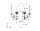
両図に示すように、各栽培筒1の上部の、栽培筒吊持部2に吊持される位置には、栽培筒1の本体11に接続された水平フレーム部材14を介して、一対のローラ部材15が設けられている。
当該ローラ部材15は、同図Z方向の軸により回転可能とされており、当該ローラ部材15が栽培筒吊持部2に支持されることで、搬送機構3のスクリュー31による各栽培筒1の搬送時に、当該各栽培筒1を栽培筒吊持部2上で上記搬送方向(X方向)へ摺動させる摺動機構として機能する。当該摺動機構により、各栽培筒1をよりスムースに搬送させることができるとともに、各栽培筒1の摩耗や破損を防止することができる。
図5に示すように、各栽培筒1において、各ローラ部材15及びそれを保持する水平フレーム部材14の搬送方向における幅(長さ)は、上記スクリュー31の定植側の端部におけるピッチP1に合致している。これにより、定植側において各栽培筒1を新たにスクリュー31に係合させて定植作業を行う際に、各栽培筒1をスクリュー31に容易に位置決めすることができる。
また、図4に示すように、スクリュー31は、回転駆動時において、ローラ等で構成されたスクリューガイド33によってガイドされる。
図6は、図4に示した搬送機構3のスクリュー31の一部省略A-A断面図である。また図7は、図6のB部分の拡大図であり、図8は、図6のC部分の拡大図である。
これらの図に示すように、スクリュー31は、所定長(例えば1200mm程度)の複数(例えば10本程度)のスクリュー部材35が、連結キー36によって連結されて構成されている。
各スクリュー部材35は、その両端部において、その回転軸方向に連結穴(図10の連結穴44(大径部44a及び小径部44b)参照)を有し、各連結キー36は、当該連結穴に係合する略円柱形状を有する。具体的には、各連結キー36は、円柱状のキー本体36aの表面に、当該キー本体36aよりも直径が小さい円柱状のキー歯36bが突出形成されて構成されている。
スクリュー31は各栽培筒1を1ピッチずつ搬送方向に移動させるためのものであり、そのトルクは比較的小さいため、連結キー36及び連結穴の形状を円柱状としてもその連結強度を十分に保つことができ、また円柱状にすることで、角柱形状にする場合よりも加工の手間とコストを大きく下げることができる。
また、図8に示すように、スクリュー31のスクリュー軸37の端部はスクリュー軸受38によって軸支され、当該スクリュー軸受38とスクリュー31との間には、上記各スクリュー部材35をスクリュー31の回転軸方向(X方向)へ付勢する付勢部材としてのコイルばね32を有する。
当該コイルばね32により、スクリュー部材35の連結力が維持されるとともに、スクリュー31が熱によって伸縮しその全長が変化した場合でも、各スクリュー部材35の位置を所定位置に維持することができる。
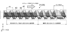
図9は、図6に示したスクリュー部材35の底面部分の斜視図である(すなわち、スクリュー部材35の天地を逆にして見た斜視図である)。また図10は、図9に示したスクリュー部材35を回転軸方向から見た図である。また図11は、図9に示したスクリュー部材35の一部拡大側面図である。
これらの図に示すように、スクリュー部材35のねじ山41のうち上記定植側の端部には、直方体形状の切欠き部43が形成されている。当該切欠き部43は、新たに定植される所定数の栽培筒1の上端をまとめて上記搬送方向へ摺動挿入させ、ねじ溝42に係合させることが可能なものである。
当該切欠き部43により、作業者は、新たな定植時に所定数の栽培筒1をスクリュー31に図9の挿入方向へ同時に挿入させることができるため、定植作業を効率化することができる。ここで所定数とは例えば3本、5本、10本等であるが、これらに限られない。
上記図5でも説明したが、図11に示すように、各栽培筒1において、各ローラ部材15及びそれを保持する水平フレーム部材14の搬送方向における幅は、上記スクリュー31の定植側の端部におけるピッチP1(スクリュー31が1回転すると、栽培筒1はピッチP1分だけ搬送方向へ進む)に合致している。
これにより、複数(同図の例では5本)の栽培筒1が切欠き部43からまとめて摺動挿入された場合に、作業者は、各栽培筒1をスクリュー31のねじ溝42にそのまま位置決めすることができ、各栽培筒1の位置を調整するための余計な作業を省いて各栽培筒1を搬送方向にそのままスムースに搬送することができる。
また、上述したように、スクリュー31のピッチは、定植側から収穫側にかけて徐々に(段階的に)大きくなるように設計されている。定植側の(最も小さい)ピッチは例えば50mmであり、それから収穫側へ向かって例えば100mm、150mm、200mmと段階的に拡大する。同一のピッチとなるピッチ数は、作業者が定植側においてまとめて定植する栽培筒1の本数及び収穫側においてまとめて収穫する栽培筒1の本数と合致し、またはそれらの本数の整数倍とされてもよい。
図12は、図9に示したスクリュー部材35の略式展開図である。
同図に示すように、スクリュー部材35の定植側端部において切欠き部43が設けられた部分のねじ山41及びねじ溝42は、停留部45を有する。当該停留部45は、各栽培筒1の搬送方向(X方向)への搬送を規制し、上記各栽培筒1をスクリュー31の回転方向と平行な方向へ案内する停留部45を有する。
すなわち、上記定植側端部のねじ山41及びねじ溝42は、その螺旋状の軌道が切欠き部43のやや手前の位置で一旦停止し、回転軸の平行方向(Y方向)に軌道修正され、切欠き部43をやや過ぎた位置から再び螺旋状の軌道に戻るような形状とされている。
当該停留部45が設けられることで、切欠き部43を介して挿入された各栽培筒が、スクリュー31の回転に伴って移動する際に、切欠き部43の角に接触したり引っ掛かったりして損傷してしまうのを防ぐことができ、ひいてはその損傷片等が栽培筒1の苗V上に落下して、苗Vに異物が混入してしまうことを防ぐことができる。
[領域毎に異なる養液の供給]
本実施形態においては、水耕栽培システム100は、栽培筒1の苗Vに供給する養液を、領域毎に異ならせることができる。図13は、水耕栽培システム100を、供給養液毎の領域に分割した様子を示した図である。
本実施形態においては、水耕栽培システム100は、栽培筒1の苗Vに供給する養液を、領域毎に異ならせることができる。図13は、水耕栽培システム100を、供給養液毎の領域に分割した様子を示した図である。
同図に示すように、水耕栽培システム100は、隣接間隔(すなわち、対応するスクリュー31のピッチ)が同一の栽培筒1の領域ごとに異なる養液(例えばスクリュー31の異なるピッチの数が3つであれば、3つの異なる養液)を供給することができる。
上述したように、栽培筒1は垂直方向に吊持されていることから、養液供給管8から養液受管13を介して供給される養液は、栽培筒1内において垂直方向へ高速に流通することから、領域毎に異なる養液を用いた場合でも、それらのコンタミネーションが極力防止される。したがって、横型の苗床が用いられる場合に比べて、領域毎に養液を異ならせることの効果を最大限に引き出すことができる。
これにより水耕栽培システム100は、苗Vの生長に合わせて成分や濃度の異なる養液を供給することができ、例えば所定の生長段階において、それ以前の養液を異なる成分の養液に置換することで、低カリウムレタス等の機能性野菜を容易に栽培することができる。
[まとめ]
以上説明したように、本実施形態によれば、水耕栽培システム100は、栽培筒吊持部2に吊持され搬送方向に一列に配列された縦型の栽培筒1を搬送機構3(1本のスクリュー31)によって水平搬送することで、横型の苗床を用いる場合に比べて簡素な機構により苗床を搬送できる。また、栽培筒吊持部2が栽培筒1を吊持することで、搬送機構3に対して栽培筒1の自重がかからないため、搬送機構3の構造を簡素化し低コスト化することができる。さらに、高さ方向において搬送機構3と同一以下の位置に養液供給管8を有することから、搬送機構3が養液に晒されて腐食してしまうことがないため、耐久性を向上させることができる。
以上説明したように、本実施形態によれば、水耕栽培システム100は、栽培筒吊持部2に吊持され搬送方向に一列に配列された縦型の栽培筒1を搬送機構3(1本のスクリュー31)によって水平搬送することで、横型の苗床を用いる場合に比べて簡素な機構により苗床を搬送できる。また、栽培筒吊持部2が栽培筒1を吊持することで、搬送機構3に対して栽培筒1の自重がかからないため、搬送機構3の構造を簡素化し低コスト化することができる。さらに、高さ方向において搬送機構3と同一以下の位置に養液供給管8を有することから、搬送機構3が養液に晒されて腐食してしまうことがないため、耐久性を向上させることができる。
[変形例]
本発明は上述の実施形態にのみ限定されるものではなく、本発明の要旨を逸脱しない範囲内において種々変更され得る。
本発明は上述の実施形態にのみ限定されるものではなく、本発明の要旨を逸脱しない範囲内において種々変更され得る。
上述の実施形態において、搬送機構3はピッチが段階的に大きくなるスクリュー31によって構成された。しかし、搬送機構3はこれに限られない。例えば、搬送機構3として、図14に示すようなリンク機構を用いることもできる。
同図は、当該搬送機構3としてのリンク機構50の略式透過側面図である。同図に示すように、リンク機構50は、天井部51及びアーム部52を有する。
アーム部52は例えば細長い菱形状の板部材で構成され、その両端部には、Z方向の軸回りに回転可能な上部ローラ54及び下部ローラ55が設けられる。またアーム部52は例えばその上部ローラ側において、栽培筒1の水平フレーム部材14の側壁と、支軸53を介して回転可能に連結されている。栽培筒1は、上述の実施形態と同様の、栽培筒吊持部2上を摺動可能なローラ部材15を有する。
また天井部51は、その高さ(天井部51と栽培筒吊持部2との間の距離)が斜面を介して段階的に小さくなるように形成されている。
この構成により、最も定植側(同図左端)の栽培筒1が搬送方向(X方向右側)へ移動すると、栽培筒1に接続されたアーム部52の下部ローラ55がその1つ前の栽培筒1を押すことで、複数の栽培筒1が連動して搬送方向へ移動する。それとともに、上記天井部51の高さが段階的に小さくなっていることから、それに沿って上部ローラ54の位置が下方へ移動するとともに、支軸53を中心にアーム部52が搬送方向へ回転し、それにより下部ローラ55の位置も搬送方向へ移動することから、下部ローラ55によって押される1つ前の栽培筒1との間の距離も、天井部51の高さの変化に伴って大きくなる。
このような構成により、上記ピッチの異なるスクリュー31と同様に、栽培筒1間の間隔を段階的に広げながら各栽培筒1を搬送方向へ搬送することが可能となる。
上述の実施形態では、摺動部材としてのローラ部材15は各栽培筒1の上部(栽培筒吊持部2に支持される部分)に設けられた。しかし、ローラ部材は栽培筒1に設けられる代わりに、栽培筒吊持部2に設けられてもよい。
図15は、ローラ部材が栽培筒吊持部2に設けられた場合の摺動機構の構成を搬送方向側から示した図である。同図に示すように、栽培筒吊持部2の底面及び側面には、栽培筒1の水平フレーム部材14を搬送方向へ摺動させるための複数の円柱状のホイール61(いわゆるミニミニホイール)が設けられている。当該ホイール61は、搬送方向の定植側から収穫側に亘って多数隣接して設けられ、ホイールコンベアとして機能する。
各ホイール61は、円柱状に限らず、複数の円盤状ローラがZ方向に連結されて構成されていてもよい。また同図では搬送機構としてスクリュー31が示されているが、当該スクリュー31に代えて上記リンク機構50が用いられてもよい。
これにより、栽培筒1の構造をより簡素化することができ、栽培筒1を定植する際の作業性が向上する。
上述の実施形態におけるスクリュー31の切欠き部43の長さは、図示したものに限られず、より多くの本数の栽培筒1をまとめて摺動挿入できるものであってもよい。また、上記スクリュー31の停留部45の長さ(面積)も、図示したものに限られず、適宜変更可能である。
また、スクリュー31の異なるピッチの数も上述の実施形態で図示したものに限られず、適宜変更可能であり、またその場合、ピッチの数に応じて用いる異なる養液の数も併せて適宜変更可能である。
上述の実施形態においては、苗が移植された苗床として栽培筒1が示された。しかし、苗床は筒状に限られず、側面に苗を保持可能な円柱状の発泡体(スポンジ等)や、側面から苗を吊下げ可能な棒状体等、長尺状のものであればどのような形態のものであっても構わない。
上述の実施形態では、養液は、養液タンクからポンプによって養液供給管8を流通し、栽培筒1の養液受管13の受け口まで供給され、当該養液受管13を介して栽培筒の内部へ供給された。しかし、養液供給管8に代えて、スクリュー31の軸方向の中心に穴が設けられ、当該スクリュー1の穴を通して各栽培筒1へ養液が供給されてもよい。
1…栽培筒
2…栽培筒吊持部
3…搬送機構
4…支柱フレーム
5…LED
7…採光装置
8…養液供給管
9…栽培筒下部ガイド
10…空調ダクト
11…栽培筒本体
12…植付枝管
13…養液受管
14…水平フレーム部材
15…ローラ部材
31…スクリュー
32…コイルばね
35…スクリュー部材
36…連結キー
41…ねじ山
42…ねじ溝
43…切欠き部
44…連結穴
45…停留部
50…リンク機構
51…天井部
52…アーム部
53…支軸
54…上部ローラ
55…下部ローラ
61…ホイール
V…苗
2…栽培筒吊持部
3…搬送機構
4…支柱フレーム
5…LED
7…採光装置
8…養液供給管
9…栽培筒下部ガイド
10…空調ダクト
11…栽培筒本体
12…植付枝管
13…養液受管
14…水平フレーム部材
15…ローラ部材
31…スクリュー
32…コイルばね
35…スクリュー部材
36…連結キー
41…ねじ山
42…ねじ溝
43…切欠き部
44…連結穴
45…停留部
50…リンク機構
51…天井部
52…アーム部
53…支軸
54…上部ローラ
55…下部ローラ
61…ホイール
V…苗
Claims (11)
- 植物の苗が移植された複数の長尺状の苗床と、
前記複数の苗床が、前記苗の定植側から収穫側へ向かう所定の水平方向に配列された状態で当該各苗床を吊持する吊持部と、
前記複数の苗床を、前記所定の水平方向における各苗床の間隔を、段階的または連続的に拡げながら当該所定の水平方向へ搬送する搬送機構と
を具備する水耕栽培システム。 - 請求項1に記載の水耕栽培システムであって、
前記各苗床または前記搬送機構は、前記各苗床の搬送時に当該各苗床を前記所定の水平方向へ摺動させる摺動機構を有する
水耕栽培システム。 - 請求項1または2に記載の水耕栽培システムであって、
前記搬送機構は、前記所定の水平方向へ向かって段階的にピッチが大きくなるように形成され、前記各苗床の上端が係合可能なねじ溝を有する1本のスクリューを有する
水耕栽培システム。 - 請求項3に記載の水耕栽培システムであって、
前記スクリューのねじ山のうち前記定植側の端部は、新たに定植される所定数の苗床の上端をまとめて前記所定の水平方向へ摺動挿入させ前記ねじ溝に係合させることが可能な切欠き部を有する
水耕栽培システム。 - 請求項3または4に記載の水耕栽培システムであって、
前記苗床は、前記吊持部に吊持される位置に、前記各苗床の搬送時に当該各苗床を前記吊持部上で前記所定の水平方向へ摺動させるローラ部材を有し、
前記ローラ部材の前記所定の水平方向における幅は、前記スクリューの前記定植側の端部のピッチと合致する
水耕栽培システム。 - 請求項4または5のいずれかに記載の水耕栽培システムであって、
前記スクリューのうち、前記切欠き部が設けられた部分のねじ山及びねじ溝は、前記各苗床の前記所定の水平方向への搬送を規制し前記各苗床を当該スクリューの回転方向と平行な方向へ案内する停留部を有する
水耕栽培システム。 - 請求項3乃至6のいずれかに記載の水耕栽培システムであって、
前記スクリューは、両端部において当該スクリューの回転軸方向に連結穴がそれぞれ形成された所定長の複数のスクリュー部材と、当該複数のスクリュー部材の前記各連結穴に係合しそれぞれ2つのスクリュー部材を連結する連結部材とを有し、
前記搬送機構は、前記スクリューの端部を軸支するスクリュー支持部と、当該スクリュー支持部と前記スクリューとの間に設けられ前記各スクリュー部材を前記回転軸方向へ付勢する付勢部材とを有する
水耕栽培システム。 - 請求項1乃至7のいずれかに記載の水耕栽培システムであって、
高さ方向において前記搬送機構と同一以下の位置に設けられ、前記各苗床に養液を供給する養液供給部をさらに具備する
水耕栽培システム。 - 請求項1乃至8のいずれかに記載の水耕栽培システムであって、
前記各苗床は、当該各苗床の側面から各苗床の長手方向の垂直方向に突出して設けられ、前記養液供給部から供給される養液を上部から受けて前記苗床内部へ流通させる養液受管を有する
水耕栽培システム。 - 請求項1乃至9のいずれかに記載の水耕栽培システムであって、
前記養液供給部は、苗床の領域ごとに異なる養液を供給する
水耕栽培システム。 - 請求項1乃至10のいずれかに記載の水耕栽培システムであって、
前記各苗床の前記所定の水平方向に垂直な面上における揺動を規制するガイド部材をさらに具備する
水耕栽培システム。
Priority Applications (3)
| Application Number | Priority Date | Filing Date | Title |
|---|---|---|---|
| US16/310,540 US11026379B2 (en) | 2016-06-17 | 2017-05-01 | Hydroponic cultivation system comprising seedbeds and a transport mechanism |
| EP17813035.7A EP3473086B1 (en) | 2016-06-17 | 2017-05-01 | Hydroponic system |
| CN201780037475.XA CN109561665B (zh) | 2016-06-17 | 2017-05-01 | 水培培育系统 |
Applications Claiming Priority (2)
| Application Number | Priority Date | Filing Date | Title |
|---|---|---|---|
| JP2016120846A JP6812668B2 (ja) | 2016-06-17 | 2016-06-17 | 水耕栽培システム |
| JP2016-120846 | 2016-06-17 |
Publications (1)
| Publication Number | Publication Date |
|---|---|
| WO2017217130A1 true WO2017217130A1 (ja) | 2017-12-21 |
Family
ID=60664033
Family Applications (1)
| Application Number | Title | Priority Date | Filing Date |
|---|---|---|---|
| PCT/JP2017/017200 Ceased WO2017217130A1 (ja) | 2016-06-17 | 2017-05-01 | 水耕栽培システム |
Country Status (5)
| Country | Link |
|---|---|
| US (1) | US11026379B2 (ja) |
| EP (1) | EP3473086B1 (ja) |
| JP (1) | JP6812668B2 (ja) |
| CN (1) | CN109561665B (ja) |
| WO (1) | WO2017217130A1 (ja) |
Cited By (10)
| Publication number | Priority date | Publication date | Assignee | Title |
|---|---|---|---|---|
| CN109511545A (zh) * | 2018-12-21 | 2019-03-26 | 重庆市农业科学院 | 一种马铃薯脱毒种苗水培生产装置及方法 |
| WO2019183244A3 (en) * | 2018-03-21 | 2019-10-31 | Mjnn Llc | Vertical grow tower conveyance system for controlled environment agriculture |
| US11570958B2 (en) | 2019-09-20 | 2023-02-07 | Mjnn Llc | Catch mechanism facilitating loading of vertical grow towers onto grow lines in a vertical farm system |
| US11700804B2 (en) | 2018-10-30 | 2023-07-18 | Mjnn Llc | Production facility layout for automated controlled environment agriculture |
| US11832569B2 (en) | 2018-10-30 | 2023-12-05 | Mjnn Llc | Grow tower processing for controlled environment agriculture system |
| US11856902B2 (en) | 2019-09-20 | 2024-01-02 | Mjnn Llc | Production facility layouts for automated controlled environment agriculture |
| US11944049B2 (en) | 2019-09-20 | 2024-04-02 | Mjnn Llc | Vertical grow tower conveyance system for controlled environment agriculture including tower shuttle |
| US12089545B1 (en) | 2020-09-25 | 2024-09-17 | Mjnn Llc | Grow towers with overlapping funnels for automated agriculture production |
| US12478006B2 (en) | 2020-08-22 | 2025-11-25 | Mjnn Llc | Controlled environment agriculture system including multiple grow space condition zones |
| US12568892B1 (en) | 2022-08-19 | 2026-03-10 | Mjnn Llc | Plant support structure for improving canopy light exposure |
Families Citing this family (10)
| Publication number | Priority date | Publication date | Assignee | Title |
|---|---|---|---|---|
| US10212892B2 (en) * | 2012-07-10 | 2019-02-26 | Once Innovatians, Inc. | Light sources adapted to spectral sensitivity of plant |
| BE1023219B1 (nl) * | 2015-06-30 | 2017-01-03 | Green Production Systems Bvba | Teelsysteem |
| US11089744B2 (en) * | 2017-09-18 | 2021-08-17 | Stem Cultivation, Inc. | Cultivation system and methods |
| US11483981B1 (en) * | 2018-05-14 | 2022-11-01 | Crop One Holdings, Inc. | Systems and methods for providing a low energy use farm |
| CN108901806B (zh) * | 2018-07-11 | 2020-10-27 | 福建省中科生物股份有限公司 | 一种植物水培装置及植物水培方法 |
| JP7272941B2 (ja) * | 2018-12-20 | 2023-05-12 | 鋼鈑商事株式会社 | 植物水耕栽培用筒状体、水耕栽培ユニット及び水耕栽培システム |
| TWI680708B (zh) * | 2019-01-11 | 2020-01-01 | 邱鈺礎 | 植株槽控制結構 |
| WO2022187958A1 (en) * | 2021-03-10 | 2022-09-15 | 11778757 Canada Inc. | System for rotating horticulture towers |
| CN115399171B (zh) * | 2022-09-21 | 2023-06-23 | 龙泉市林业科学研究院 | 一种可调育苗盘 |
| WO2024145284A1 (en) * | 2022-12-27 | 2024-07-04 | Mjnn Llc | Tower indexing via tower interleaving |
Citations (4)
| Publication number | Priority date | Publication date | Assignee | Title |
|---|---|---|---|---|
| JPH03127919A (ja) * | 1989-10-11 | 1991-05-31 | Kobe Kigyo Kk | トラフ移動型水耕栽培施設 |
| JPH0576252A (ja) * | 1991-09-20 | 1993-03-30 | Hitachi Ltd | 立体可動式栽培装置 |
| JP2008154505A (ja) * | 2006-12-25 | 2008-07-10 | Mebiol Kk | 植物栽培システムおよび植物栽培方法 |
| US20150223418A1 (en) * | 2014-02-13 | 2015-08-13 | Fred Collins | Light-weight modular adjustable vertical hydroponic growing system and method |
Family Cites Families (25)
| Publication number | Priority date | Publication date | Assignee | Title |
|---|---|---|---|---|
| US4166341A (en) * | 1974-08-13 | 1979-09-04 | Bent Vestergaard | Method and apparatus for cultivation of plants grown singly in separate beds |
| JPS5184948U (ja) | 1974-12-27 | 1976-07-07 | ||
| US4028847A (en) * | 1976-02-19 | 1977-06-14 | General Mills, Inc. | Apparatus for producing plants |
| JPS5327535A (en) * | 1976-08-19 | 1978-03-14 | Kyowa Kagaku Kougiyou Kk | Hydroponics and its device |
| IT1155847B (it) * | 1978-02-27 | 1987-01-28 | Schmidt Maria | Procedimento per la coltivazione a ciclo continuo di vegetali ed impianto verticale che realizza detto procedimento |
| US4337986A (en) * | 1978-08-02 | 1982-07-06 | General Mills, Inc. | Method and apparatus for increasing the spacing between plants in accordance with their growth rate |
| US4216618A (en) * | 1978-08-02 | 1980-08-12 | General Mills, Inc. | Method and apparatus for increasing the spacing between plants in accordance with their growth rate |
| DE3221646C3 (de) * | 1982-06-08 | 1997-05-07 | Veit Gmbh & Co | Fördereinrichtung, insbesondere Hängeförderung |
| US4476651A (en) * | 1983-01-27 | 1984-10-16 | Geoffrey Drury | Apparatus and method for transporting growing plants |
| US6173529B1 (en) * | 1987-03-04 | 2001-01-16 | Malcolm Glen Kertz | Plant growing room |
| JPH0391423A (ja) * | 1989-09-01 | 1991-04-17 | Idemitsu Kosan Co Ltd | 移動式立筒栽培装置及びそれに用いる養液供給装置 |
| JPH062013B2 (ja) * | 1990-07-25 | 1994-01-12 | 神戸企業株式会社 | トラフ移動型水耕栽培施設 |
| JPH07121190B2 (ja) * | 1990-12-20 | 1995-12-25 | 武 松岡 | 移動式作物栽培装置及び方法 |
| JP2000077499A (ja) * | 1998-09-03 | 2000-03-14 | Dainippon Screen Mfg Co Ltd | 基板処理装置 |
| JP2001069865A (ja) * | 1999-09-01 | 2001-03-21 | Toyo Bio Reactor Kk | 植物の栽培装置 |
| JP2002157641A (ja) * | 2000-11-22 | 2002-05-31 | Shinko Mex Co Ltd | 自動販売機 |
| AU2003284767A1 (en) * | 2002-11-27 | 2004-06-18 | LIM, , Sun-Ho | Hydroponic device and hydroponic pot thereof |
| US20060201058A1 (en) * | 2005-03-09 | 2006-09-14 | Ripatti Matti T | Multipurpose growing system |
| JP2008253218A (ja) * | 2007-04-06 | 2008-10-23 | Yasumasa Yoshikawa | 植物栽培装置 |
| US11026378B2 (en) * | 2009-08-03 | 2021-06-08 | University Of Wyoming | Vertical hydroponic plant production apparatus |
| US10136594B2 (en) * | 2012-05-18 | 2018-11-27 | Tower Garden, Llc | Aeroponic growing system and method |
| JP6233204B2 (ja) * | 2014-06-23 | 2017-11-22 | 株式会社安川電機 | 栽培装置 |
| US11129344B2 (en) * | 2015-01-01 | 2021-09-28 | Aravinda Raama Mawendra | Central processing horticulture |
| BE1023219B1 (nl) * | 2015-06-30 | 2017-01-03 | Green Production Systems Bvba | Teelsysteem |
| WO2018013163A1 (en) * | 2016-07-14 | 2018-01-18 | Mjnn Llc | Control and sensor systems for an environmentally controlled vertical farming system |
-
2016
- 2016-06-17 JP JP2016120846A patent/JP6812668B2/ja active Active
-
2017
- 2017-05-01 US US16/310,540 patent/US11026379B2/en active Active
- 2017-05-01 CN CN201780037475.XA patent/CN109561665B/zh active Active
- 2017-05-01 WO PCT/JP2017/017200 patent/WO2017217130A1/ja not_active Ceased
- 2017-05-01 EP EP17813035.7A patent/EP3473086B1/en active Active
Patent Citations (4)
| Publication number | Priority date | Publication date | Assignee | Title |
|---|---|---|---|---|
| JPH03127919A (ja) * | 1989-10-11 | 1991-05-31 | Kobe Kigyo Kk | トラフ移動型水耕栽培施設 |
| JPH0576252A (ja) * | 1991-09-20 | 1993-03-30 | Hitachi Ltd | 立体可動式栽培装置 |
| JP2008154505A (ja) * | 2006-12-25 | 2008-07-10 | Mebiol Kk | 植物栽培システムおよび植物栽培方法 |
| US20150223418A1 (en) * | 2014-02-13 | 2015-08-13 | Fred Collins | Light-weight modular adjustable vertical hydroponic growing system and method |
Non-Patent Citations (1)
| Title |
|---|
| See also references of EP3473086A4 * |
Cited By (24)
| Publication number | Priority date | Publication date | Assignee | Title |
|---|---|---|---|---|
| EP4197317A1 (en) | 2018-03-21 | 2023-06-21 | Mjnn Llc | Multi cavitiy vertical grow tower conveyance system |
| US11690326B2 (en) | 2018-03-21 | 2023-07-04 | Mjnn Llc | Vertical grow tower conveyance system for controlled environment agriculture |
| KR20200140803A (ko) * | 2018-03-21 | 2020-12-16 | 엠제이엔엔 엘엘씨 | 통제된 환경 농업을 위한 수직 재배 타워 컨베이어 시스템 |
| CN112105256A (zh) * | 2018-03-21 | 2020-12-18 | Mjnn有限责任公司 | 用于受控环境农业的垂直种植塔输送系统 |
| US11089741B2 (en) | 2018-03-21 | 2021-08-17 | Mjnn Llc | Vertical grow tower conveyance system for controlled environment agriculture |
| CN114847153A (zh) * | 2018-03-21 | 2022-08-05 | Mjnn有限责任公司 | 用于受控环境农业的垂直种植塔输送系统 |
| WO2019183244A3 (en) * | 2018-03-21 | 2019-10-31 | Mjnn Llc | Vertical grow tower conveyance system for controlled environment agriculture |
| CN114847153B (zh) * | 2018-03-21 | 2024-11-08 | Mjnn有限责任公司 | 用于受控环境农业的垂直种植塔输送系统 |
| AU2019240064B2 (en) * | 2018-03-21 | 2024-05-23 | Mjnn Llc | Vertical grow tower conveyance system for controlled environment agriculture |
| US11612112B2 (en) | 2018-03-21 | 2023-03-28 | Mjnn Llc | Vertical grow tower conveyance system for controlled environment agriculture |
| KR102728964B1 (ko) * | 2018-03-21 | 2024-11-12 | 엠제이엔엔 엘엘씨 | 통제된 환경 농업을 위한 수직 재배 타워 컨베이어 시스템 |
| US11832569B2 (en) | 2018-10-30 | 2023-12-05 | Mjnn Llc | Grow tower processing for controlled environment agriculture system |
| US12527267B2 (en) | 2018-10-30 | 2026-01-20 | Mjnn Llc | Production facility layout for automated controlled environment agriculture |
| US11700804B2 (en) | 2018-10-30 | 2023-07-18 | Mjnn Llc | Production facility layout for automated controlled environment agriculture |
| US12127516B2 (en) | 2018-10-30 | 2024-10-29 | Mjnn Llc | Production facility layout for automated controlled environment agriculture |
| CN109511545A (zh) * | 2018-12-21 | 2019-03-26 | 重庆市农业科学院 | 一种马铃薯脱毒种苗水培生产装置及方法 |
| US11570958B2 (en) | 2019-09-20 | 2023-02-07 | Mjnn Llc | Catch mechanism facilitating loading of vertical grow towers onto grow lines in a vertical farm system |
| US11944049B2 (en) | 2019-09-20 | 2024-04-02 | Mjnn Llc | Vertical grow tower conveyance system for controlled environment agriculture including tower shuttle |
| US12201072B2 (en) | 2019-09-20 | 2025-01-21 | Mjnn Llc | Production facility layouts for automated controlled environment agriculture |
| US11856902B2 (en) | 2019-09-20 | 2024-01-02 | Mjnn Llc | Production facility layouts for automated controlled environment agriculture |
| US12582058B2 (en) | 2019-09-20 | 2026-03-24 | Mjnn Llc | Production facility layouts for automated controlled environment agriculture |
| US12478006B2 (en) | 2020-08-22 | 2025-11-25 | Mjnn Llc | Controlled environment agriculture system including multiple grow space condition zones |
| US12089545B1 (en) | 2020-09-25 | 2024-09-17 | Mjnn Llc | Grow towers with overlapping funnels for automated agriculture production |
| US12568892B1 (en) | 2022-08-19 | 2026-03-10 | Mjnn Llc | Plant support structure for improving canopy light exposure |
Also Published As
| Publication number | Publication date |
|---|---|
| CN109561665A (zh) | 2019-04-02 |
| EP3473086A1 (en) | 2019-04-24 |
| JP2017221165A (ja) | 2017-12-21 |
| US11026379B2 (en) | 2021-06-08 |
| CN109561665B (zh) | 2021-11-09 |
| EP3473086A4 (en) | 2019-12-11 |
| JP6812668B2 (ja) | 2021-01-13 |
| US20190183076A1 (en) | 2019-06-20 |
| EP3473086B1 (en) | 2022-01-12 |
Similar Documents
| Publication | Publication Date | Title |
|---|---|---|
| WO2017217130A1 (ja) | 水耕栽培システム | |
| US11612112B2 (en) | Vertical grow tower conveyance system for controlled environment agriculture | |
| CN101647386A (zh) | 植物立体栽培塔 | |
| KR102060055B1 (ko) | 식물 재배 장치 | |
| US20210084850A1 (en) | Vertical farm irrigation system with dual return pumps | |
| US20230105146A1 (en) | Technologies for aeroponics | |
| US20230033137A1 (en) | Fault handling in controlled environment agriculture | |
| JPH03127919A (ja) | トラフ移動型水耕栽培施設 | |
| WO2019144638A1 (zh) | 植物种植装置以及植物种植方法 | |
| WO2023004320A1 (en) | Vertical indexing of grow tower segments | |
| JP7036167B2 (ja) | 水耕栽培システム | |
| JP4279379B2 (ja) | 植物栽培装置 | |
| JP6787470B2 (ja) | 水耕栽培システム | |
| CN108450317A (zh) | 水培植物栽培系统及其应用方法 | |
| CN221178600U (zh) | 一种倒栽植物系统 | |
| JP6498869B2 (ja) | 植物栽培装置及びそれを備えた植物工場設備 | |
| US11570958B2 (en) | Catch mechanism facilitating loading of vertical grow towers onto grow lines in a vertical farm system | |
| US20230225258A1 (en) | Indexing plants in two-dimensional and three-dimensional space in a controlled growing environment | |
| US20240016100A1 (en) | Managing atmospheric gas composition in a controlled agricultural environment | |
| JPH03191725A (ja) | 可搬式人工光型植物栽培装置 | |
| KR20240160930A (ko) | 회전식 식재판이 구비된 수경재배장치 | |
| HK40080321A (en) | Vertical grow tower conveyance system for controlled environment agriculture | |
| HK40034383B (en) | Vertical grow tower conveyance system for controlled environment agriculture | |
| HK40080321B (zh) | 用於受控环境农业的垂直种植塔输送系统 | |
| JPH0484834A (ja) | トラフ移動型水耕栽培施設 |
Legal Events
| Date | Code | Title | Description |
|---|---|---|---|
| 121 | Ep: the epo has been informed by wipo that ep was designated in this application |
Ref document number: 17813035 Country of ref document: EP Kind code of ref document: A1 |
|
| NENP | Non-entry into the national phase |
Ref country code: DE |
|
| ENP | Entry into the national phase |
Ref document number: 2017813035 Country of ref document: EP Effective date: 20190117 |