WO2017217352A1 - 加熱撹拌調理器 - Google Patents
加熱撹拌調理器 Download PDFInfo
- Publication number
- WO2017217352A1 WO2017217352A1 PCT/JP2017/021580 JP2017021580W WO2017217352A1 WO 2017217352 A1 WO2017217352 A1 WO 2017217352A1 JP 2017021580 W JP2017021580 W JP 2017021580W WO 2017217352 A1 WO2017217352 A1 WO 2017217352A1
- Authority
- WO
- WIPO (PCT)
- Prior art keywords
- magnet
- rotation direction
- stirring
- magnetic field
- container
- Prior art date
- Legal status (The legal status is an assumption and is not a legal conclusion. Google has not performed a legal analysis and makes no representation as to the accuracy of the status listed.)
- Ceased
Links
Images


Classifications
-
- A—HUMAN NECESSITIES
- A47—FURNITURE; DOMESTIC ARTICLES OR APPLIANCES; COFFEE MILLS; SPICE MILLS; SUCTION CLEANERS IN GENERAL
- A47J—KITCHEN EQUIPMENT; COFFEE MILLS; SPICE MILLS; APPARATUS FOR MAKING BEVERAGES
- A47J36/00—Parts, details or accessories of cooking-vessels
- A47J36/16—Inserts
- A47J36/165—Stirring devices operatively connected to cooking vessels when being removably inserted inside
-
- A—HUMAN NECESSITIES
- A47—FURNITURE; DOMESTIC ARTICLES OR APPLIANCES; COFFEE MILLS; SPICE MILLS; SUCTION CLEANERS IN GENERAL
- A47J—KITCHEN EQUIPMENT; COFFEE MILLS; SPICE MILLS; APPARATUS FOR MAKING BEVERAGES
- A47J43/00—Implements for preparing or holding food, not provided for in other groups of this subclass
- A47J43/04—Machines for domestic use not covered elsewhere, e.g. for grinding, mixing, stirring, kneading, emulsifying, whipping or beating foodstuffs, e.g. power-driven
- A47J43/046—Machines for domestic use not covered elsewhere, e.g. for grinding, mixing, stirring, kneading, emulsifying, whipping or beating foodstuffs, e.g. power-driven with tools driven from the bottom side
- A47J43/0465—Machines for domestic use not covered elsewhere, e.g. for grinding, mixing, stirring, kneading, emulsifying, whipping or beating foodstuffs, e.g. power-driven with tools driven from the bottom side with magnetic drive
-
- A—HUMAN NECESSITIES
- A47—FURNITURE; DOMESTIC ARTICLES OR APPLIANCES; COFFEE MILLS; SPICE MILLS; SUCTION CLEANERS IN GENERAL
- A47J—KITCHEN EQUIPMENT; COFFEE MILLS; SPICE MILLS; APPARATUS FOR MAKING BEVERAGES
- A47J27/00—Cooking-vessels
-
- A—HUMAN NECESSITIES
- A47—FURNITURE; DOMESTIC ARTICLES OR APPLIANCES; COFFEE MILLS; SPICE MILLS; SUCTION CLEANERS IN GENERAL
- A47J—KITCHEN EQUIPMENT; COFFEE MILLS; SPICE MILLS; APPARATUS FOR MAKING BEVERAGES
- A47J27/00—Cooking-vessels
- A47J27/004—Cooking-vessels with integral electrical heating means
-
- A—HUMAN NECESSITIES
- A47—FURNITURE; DOMESTIC ARTICLES OR APPLIANCES; COFFEE MILLS; SPICE MILLS; SUCTION CLEANERS IN GENERAL
- A47J—KITCHEN EQUIPMENT; COFFEE MILLS; SPICE MILLS; APPARATUS FOR MAKING BEVERAGES
- A47J36/00—Parts, details or accessories of cooking-vessels
- A47J36/32—Time-controlled igniting mechanisms or alarm devices
-
- A—HUMAN NECESSITIES
- A47—FURNITURE; DOMESTIC ARTICLES OR APPLIANCES; COFFEE MILLS; SPICE MILLS; SUCTION CLEANERS IN GENERAL
- A47J—KITCHEN EQUIPMENT; COFFEE MILLS; SPICE MILLS; APPARATUS FOR MAKING BEVERAGES
- A47J43/00—Implements for preparing or holding food, not provided for in other groups of this subclass
- A47J43/04—Machines for domestic use not covered elsewhere, e.g. for grinding, mixing, stirring, kneading, emulsifying, whipping or beating foodstuffs, e.g. power-driven
- A47J43/07—Parts or details, e.g. mixing tools, whipping tools
- A47J43/0716—Parts or details, e.g. mixing tools, whipping tools for machines with tools driven from the lower side
-
- A—HUMAN NECESSITIES
- A47—FURNITURE; DOMESTIC ARTICLES OR APPLIANCES; COFFEE MILLS; SPICE MILLS; SUCTION CLEANERS IN GENERAL
- A47J—KITCHEN EQUIPMENT; COFFEE MILLS; SPICE MILLS; APPARATUS FOR MAKING BEVERAGES
- A47J43/00—Implements for preparing or holding food, not provided for in other groups of this subclass
- A47J43/04—Machines for domestic use not covered elsewhere, e.g. for grinding, mixing, stirring, kneading, emulsifying, whipping or beating foodstuffs, e.g. power-driven
- A47J43/07—Parts or details, e.g. mixing tools, whipping tools
- A47J43/08—Driving mechanisms
- A47J43/085—Driving mechanisms for machines with tools driven from the lower side
-
- B—PERFORMING OPERATIONS; TRANSPORTING
- B01—PHYSICAL OR CHEMICAL PROCESSES OR APPARATUS IN GENERAL
- B01F—MIXING, e.g. DISSOLVING, EMULSIFYING OR DISPERSING
- B01F33/00—Other mixers; Mixing plants; Combinations of mixers
- B01F33/45—Magnetic mixers; Mixers with magnetically driven stirrers
- B01F33/453—Magnetic mixers; Mixers with magnetically driven stirrers using supported or suspended stirring elements
- B01F33/4533—Magnetic mixers; Mixers with magnetically driven stirrers using supported or suspended stirring elements supporting the stirring element in one point
-
- B—PERFORMING OPERATIONS; TRANSPORTING
- B01—PHYSICAL OR CHEMICAL PROCESSES OR APPARATUS IN GENERAL
- B01F—MIXING, e.g. DISSOLVING, EMULSIFYING OR DISPERSING
- B01F35/00—Accessories for mixers; Auxiliary operations or auxiliary devices; Parts or details of general application
- B01F35/20—Measuring; Control or regulation
- B01F35/22—Control or regulation
- B01F35/221—Control or regulation of operational parameters, e.g. level of material in the mixer, temperature or pressure
- B01F35/2214—Speed during the operation
- B01F35/22142—Speed of the mixing device during the operation
- B01F35/221422—Speed of rotation of the mixing axis, stirrer or receptacle during the operation
-
- B—PERFORMING OPERATIONS; TRANSPORTING
- B01—PHYSICAL OR CHEMICAL PROCESSES OR APPARATUS IN GENERAL
- B01F—MIXING, e.g. DISSOLVING, EMULSIFYING OR DISPERSING
- B01F2101/00—Mixing characterised by the nature of the mixed materials or by the application field
- B01F2101/1805—Kitchen, household equipment for mixing
Definitions
- the present disclosure relates to a heating and stirring cooker including a container to be heated and a stirring body for stirring an object to be cooked accommodated in the container. Specifically, it is related with the heating stirring cooker provided with the stirring body which is arrange
- FIG. 21 is a cross-sectional view showing a conventional rotary heating cooker described in Patent Document 1.
- the main body 101 of the rotary heating cooker is provided with a coil 104 divided into a plurality of parts and connected to the inverter 103.
- the coil 104 divided into a plurality of parts generates a high-frequency magnetic field, a low-frequency magnetic field, or a mixed magnetic field thereof according to the output of the inverter 103.
- the pan 105 formed of nonmagnetic metal is induction-heated, and the rotating blade 107 provided with the magnet 106 therein is rotated by the rotating magnetic field generated by the coil 104. .
- FIG. 22 is a cross-sectional view showing a conventional electric rice cooker described in Patent Document 2.
- the stirring motor 204 When the stirring motor 204 is driven, the driving-side magnet 205 generates a rotating magnetic field. Then, the stirring blade 201 is rotationally driven in a non-contact manner by the magnetic coupling between the rotating magnetic field and the stirring blade 201. Therefore, the rotation drive device 202 does not penetrate the rice cooking pot 203, and water leakage does not occur from the penetration portion.
- Patent Documents 3 to 5 have been proposed as means for detecting the rotational motion of the stirrer in various stirrers using magnetic coupling techniques.
- the stirrer of the stirrer of Patent Document 3 is provided with a detector that is composed of a permanent magnet at a position deviated from the rotation center of the stirrer and rotates integrally with the stirrer.
- the stirring device has a sensor that detects the position of the detector in response to the magnetism of the detector. Thereby, the rotation speed of the stirring member is detected, and the rotation speed of the stirring member is controlled based on the detection result.
- a plurality of magnetic detection sensors that are magnetically shielded from the drive magnet and detect the magnetism of the stirring rotor are disposed below the container.
- the plurality of magnetic detection sensors are connected by a parallel circuit. Thereby, it can be detected that the stirring rotor is detached in the container, and the stirring rotor is returned to the original position by performing control such as temporarily rotating the drive magnet to a low speed. .
- FIG. 23 is a cross-sectional view showing a conventional stirring device described in Patent Document 5.
- a magnetic operating body 302 is disposed inside a container 301, and a driving device 303 for rotating the magnetic operating body 302 is disposed below the container 301.
- the driving device 303 is supported by a force sensor 304.
- the force sensor 304 continuously monitors the apparent weight of the driving device 303 to detect the magnitude of the magnetic force between the magnetic operating body 302 and the driving device 303. Thereby, it is possible to detect that the magnetic operating body 302 has started not to be interlocked or detached without checking the inside of the container 301 of the stirring device.
- JP-A-8-35664 JP 2011-229612 A Japanese Patent Application Laid-Open No. 2011-5381 Japanese Unexamined Patent Publication No. 2000-126777 JP 2001-62274 A
- This disclosure provides a heating and stirring cooker that suppresses an increase in the size of the apparatus, efficiently stirs the object to be cooked, and further improves usability.
- the heating and stirring cooker is a main body, a container disposed in the main body, and a stirring body disposed in the container so as to be detachable with respect to the container.
- a stirring body having a blade that stirs the food to be cooked, and a magnet disposed at a position facing the inner bottom of the container in a state where the stirring body is disposed in the container, and is rotated in the main body.
- a magnetic field generating unit that generates a magnetic field and applies a rotational force generated by the rotating magnetic field to the magnet, and a control unit that is disposed in the main body and controls the magnetic field generating unit.
- control unit switches the rotation direction of the rotating magnetic field between the normal rotation direction and the reverse rotation direction opposite to the normal rotation direction, and the number of rotations M in the reverse rotation direction is in the positive rotation direction.
- the magnetic field generator is configured to be controlled so as to be smaller than the number of rotations N of the motor.
- the stirring object is agitated from the direction opposite to the rotation in the forward rotation direction by rotating the stirring body by combining the forward rotation direction and the reverse rotation direction at different ratios and stirring the cooking object.
- the rotational force of the body can be applied, and stirring can be performed while releasing the increase factor of the load applied to the stirring body due to the bias of the object to be cooked.
- the stirring body decelerates or stops due to overload, it is combined with the rotation of the stirring body in the reverse rotation direction, so it escapes from this state without human intervention and continues to stir the food. be able to.
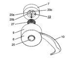
- FIG. 1 is a perspective view illustrating the entire heating and stirring cooker according to the embodiment of the present disclosure.
- FIG. 2 is a plan view showing a state where the lid of the heating and stirring cooker in the same embodiment is removed.
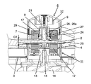
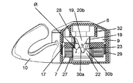
- 3 is a longitudinal sectional view taken along the line III-III in FIG.
- FIG. 4 is an enlarged cross-sectional view of the portion A in FIG. 3 when the magnetic gap is G1.
- FIG. 5 is an enlarged cross-sectional view of a portion A in FIG. 3 when the magnetic gap is G2.
- FIG. 6A is a bottom view showing a magnet of the stirrer in the same embodiment.
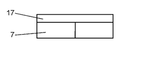
- FIG. 6B is a side view showing a magnet of the stirring body in the same embodiment.
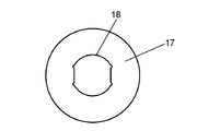
- FIG. 6C is a plan view showing a magnet of the stirrer in the same embodiment.
- FIG. 7A is an exploded perspective view of the stirring body in the same embodiment as viewed from below.
- FIG. 7B is an exploded perspective view of the stirring body in the same embodiment as viewed from above.
- FIG. 8 is a cross-sectional view showing a state in which the claw of the stirrer is engaged with the engaging portion in the same embodiment.
- FIG. 9 is a cross-sectional view showing a state in which the claw of the stirring body in the same embodiment is rising on the inclined surface of the engaging portion.
- FIG. 10 is a cross-sectional view showing a state in which the claw of the stirring member in the embodiment is disengaged from the engaging portion and the magnet is raised.
- FIG. 11 is a cross-sectional view showing a state in which the claw of the stirring member in the same embodiment is moving down the inclined surface of the engaging portion.
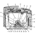
- 12 is a cross-sectional view taken along the line III-III in FIG.
- FIG. 13 is an enlarged cross-sectional view of the portion B in FIG. 12 when the magnetic gap is G1.
- FIG. 14 is an enlarged cross-sectional view of the portion B in FIG. 12 when the magnetic gap is G2.
- FIG. 15 is a cross-sectional view showing the flow of magnetic force in the magnetic coupling when the magnetic gap is G1.
- FIG. 16 is a cross-sectional view showing the flow of magnetic force in the magnetic coupling when the magnetic gap is G2 in the configuration having the clutch portion.
- FIG. 17 is a cross-sectional view showing the flow of magnetic force in a magnetic coupling when a repulsive force is acting between magnets in a configuration that does not have a clutch portion.
- FIG. 18 is a diagram schematically showing the rotational deviation angle of the magnetic coupling and the force acting on the magnet.
- FIG. 19 is a diagram showing a correlation between the rotational deviation angle of the magnetic coupling and the rotational torque.
- FIG. 20 is a diagram showing the correlation between the rotational deviation angle of the magnetic coupling and the range in which the magnetic force flows on the radially outer side of the apparatus-side magnet.
- FIG. 21 is a cross-sectional view showing a conventional rotary heating cooker.
- FIG. 22 is a cross-sectional view showing a conventional electric rice cooker.
- FIG. 23 is a cross-sectional view showing a conventional stirring device.
- the inventors of the present invention have obtained the following knowledge as a result of intensive studies on a heating and stirring cooker using a magnetic coupling in order to further improve the user-friendliness while suppressing an increase in size.
- the load applied to the stirrer fluctuates momentarily during the stir cooking with changes in the manner in which the objects to be cooked overlap each other and the manner of contact with the container.
- the load applied to the stirrer changes from moment to moment as the to-be-cooked object is heated, causing changes in hardness, moisture movement, evaporation, and the like.
- the apparatus in order to cope with the fluctuation of the load applied to the stirrer as described above, if a sufficiently large torque is generated to stir, the apparatus becomes large. That is, a motor that generates a driving force for stirring, a power transmission unit that transmits the driving force to the stirring body, a power source that supplies power to the motor, and the like increase in size, and the weight of the apparatus also increases.
- the thickness of the mounting plate and the thickness of the pan on which the pan is placed are large between the coil and the permanent magnet provided on the rotary blade.
- the magnetic gap is about 5 mm to 15 mm.
- the stronger the magnetic gap the weaker the magnetic coupling.
- a configuration in which the magnetic flux generated from the coil and the magnetic flux formed by the permanent magnets are sufficiently linked is required, and the device becomes large.
- stirring the cooking object while heating with a large torque causes the cooking object to boil down and leads to a loss in the quality of cooking.
- the stirring effect in cooking is, for example, heating cooking of a solid-centered food that has little moisture and convection cannot be expected, and cooking that is concerned about burning due to evaporation of moisture, etc. It suppresses heating unevenness and scorching.
- the user himself uses a cooking tool such as chopsticks or a spatula to turn the food to be turned upside down, upside down, to collect, or to scatter the food to be heated evenly.
- the operation is performed intermittently or continuously.
- the blades of the stirring body are physically acted on the object to be cooked.
- heating unevenness and scorching factors in cooking are as follows: arrangement of heating means such as a heater for heating the container, difference in heat conduction, position of the cooking object in the container, presence or absence of convection, and further The heat capacity due to the density is complicatedly related. For this reason, in order to suppress uneven heating and scorching for cooked foods that are not uniform in shape and size, the arrangement positions in the container are interchanged. It is necessary to prevent the object to be cooked from being heated in a state where it stays in a certain place by promoting the change of the contact surface to be contacted.
- the inventors thought that if the object to be cooked can be stirred efficiently, the usability can be improved without increasing the size of the apparatus.
- the drive-side magnet continues to rotate even if the stirring body becomes non-rotatable. For this reason, since the repulsive force between the magnetic couplings increases as the polarity of the opposing magnets between the stirrer and the drive side device approaches the same polarity, the stirrer steps out of rotation of the rotating magnetic field, It leaves from the center of rotation.
- Patent Document 3 it is a configuration that can detect the separation of the stirring body after the separation.
- a heating and stirring cooker once the stirrer is detached, it becomes difficult to return the stirrer to the original position because the object to be cooked becomes resistance.
- the inventors will continue the stirring operation if the possibility that the stirring body is detached before the stirring body is detached or the possibility that the stirring body is detached can be reduced. I thought it was possible to improve usability.
- a heating and stirring cooker is a main body, a container that is disposed in the main body, and in which the object to be cooked is stored, and a stirring body that is detachably disposed in the container.
- a stirring body having a blade that stirs the object to be cooked in the container, and a magnet disposed at a position facing the inner bottom of the container in a state where the stirring body is disposed in the container, and disposed in the main body.
- a magnetic field generating unit that generates a rotating magnetic field and applies a rotational force generated by the rotating magnetic field to the magnet, and a control unit that is disposed in the main body and controls the magnetic field generating unit.
- control unit switches the rotation direction of the rotating magnetic field between the normal rotation direction and the reverse rotation direction opposite to the normal rotation direction, and the number of rotations M in the reverse rotation direction is in the positive rotation direction.
- the magnetic field generator is configured to be controlled so as to be less than the number of rotations N of the motor.
- the magnetic field generation unit is controlled so that the rotation direction of the rotating magnetic field is switched between the normal rotation direction and the reverse rotation direction opposite to the normal rotation direction, and the number of rotations M in the reverse rotation direction is Since it is less than the number N of rotations in the forward rotation direction, it is possible to remove the increase factor of the rotational load and continue the stirring. Therefore, since the to-be-cooked object can be stirred efficiently, the enlargement of the apparatus can be suppressed. Thereby, the usability of the heating and stirring cooker can be improved.
- control unit rotates when the rotating magnetic field rotates a predetermined number of rotations in the forward rotation direction and the reverse rotation direction, and changes in the rotation state of the stirring body.
- the rotation direction of the rotating magnetic field may be switched in at least one of the cases when the signal is detected.
- the rotating magnetic field is rotated when the rotating magnetic field rotates a predetermined number of rotations in the forward rotation direction and the reverse rotation direction, and at least when a change in the state of the rotating magnetic field is detected. Since the rotation direction is switched, the increase in load is suppressed, or even when the stirrer is stopped, the increase factor of the rotation load can be efficiently removed and the stirring can be continued.
- the heating and stirring cooker according to another aspect of the present disclosure is configured such that the rotation number of the rotating magnetic field is switched when the rotating magnetic field rotates a predetermined number of rotations in the forward rotation direction and the reverse rotation direction.
- the ratio of the number of rotations M to N may be in the range of 0.1 to 0.9.
- the object to be cooked can be efficiently stirred by increasing the number of rotations in the forward rotation direction while suppressing an increase in load.
- the heating and stirring cooker according to another aspect of the present disclosure is configured such that the rotation number of the rotating magnetic field is switched when the rotating magnetic field rotates a predetermined number of rotations in the forward rotation direction and the reverse rotation direction.
- M may be in the range of 1-2.
- the number of rotations in the reverse rotation direction can be reduced within a range where suppression of increase in load can be expected, and the food to be cooked efficiently. Can be stirred.
- the magnetic field generation unit includes a device-side magnet disposed at a position facing the magnet, and a rotation driving unit that rotates the device-side magnet, Even if a detection unit is provided in the vicinity of the apparatus-side magnet, which is disposed in the main body and detects a change in the rotational state of the stirring body by detecting the state of magnetic coupling between the magnet and the apparatus-side magnet. Good.
- the detection unit may detect a change in the flow of magnetic force in the magnetic coupling between the magnet and the apparatus-side magnet.
- the control unit when the rotating magnetic field is rotating in the positive rotation direction, the control unit is configured to detect the magnetic force in the magnetic coupling between the magnet and the apparatus-side magnet. When a change in flow is detected, the rotation direction of the rotating magnetic field may be switched to the reverse rotation direction.
- the number M of rotations in the reverse rotation direction after the rotation direction of the rotation magnetic field is switched to the reverse rotation direction is 2 or less, and the rotation magnetic field has rotated M times.
- the rotation direction of the rotating magnetic field may be switched to the positive rotation direction.
- the lump of the object to be cooked that causes the stirring body to stop can be broken and scattered, and the stirring can be continued by rotating in the normal rotation direction again.
- the detection unit is provided outside the device-side magnet in the radial direction with respect to the rotation center of the device-side magnet, and is provided at a position facing the device-side magnet. You may detect the change of the flow of the magnetic force in the outer side of the apparatus side magnet.
- the blade gathers the objects to be cooked when the blade is rotating in the normal rotation direction, and the blade is rotating in the reverse rotation direction. You may be comprised so that the to-be-cooked thing gathered together may be destroyed.
- the food to be cooked can be efficiently stirred, and the mass of the food to be cooked that has increased the rotational load can be broken.
- FIG. 1 is a perspective view illustrating the entire heating and stirring cooker according to the embodiment of the present disclosure.
- FIG. 2 is a plan view showing a state where the lid of the heating and stirring cooker in the same embodiment is removed.
- 3 is a longitudinal sectional view taken along the line III-III in FIG. 4 and 5 are cross-sectional views when the magnetic gap is G1, which is enlarged for part A in FIG. 3, and are cross-sectional views when the magnetic gap is G2, enlarged for part A in FIG. .
- the heating and stirring cooker 100 includes a main body 1 in which an object to be cooked and the like is stored, and a lid 5 that covers the main body 1.
- a container 2 is disposed inside the main body 1.
- the container 2 is stored in the container storage portion 3 of the main body 1.
- the container 2 includes an inner bottom portion and an inner peripheral portion, and has an opening on the upper side.
- the object to be cooked is stored in the container 2 and cooked.
- the inner bottom portion and the inner peripheral portion respectively constitute an inner peripheral surface and an inner bottom surface that are inner surfaces of the container 2.
- the main body 1 includes an inner wall and an outer wall and has an opening on the upper side.
- the container storage portion 3 is formed by the inner wall of the main body 1.
- a heater 4 that is a heating means is disposed at the bottom of the container storage unit 3.
- the heater 4 is in contact with the lower surface of the container 2 to transmit heat to the container 2.
- the heater 4 has a ring shape in plan view.
- the heater 4 is disposed along the lower surface of the container 2 when the container 2 is stored in the container storage unit 3.
- the container 2 receives heat from the heater 4 and generates heat.
- a lid 5 that covers the opening of the main body 1 is arranged above the main body 1.
- the lid 5 is attached to the main body 1 so as to be rotatable in the vertical direction with respect to the main body 1.
- a stirring body 6 is disposed in the container 2.
- the stirring body 6 includes a storage unit 9 and blades 10 formed around the storage unit 9. Inside the storage portion 9, a magnet 7 made of a permanent magnet and a clutch portion 8 are stored.
- the stirring body 6 is detachably disposed in the container 2 with respect to the inner bottom portion of the container 2.
- the blade 10 rotates with the rotation of the stirring body 6 to stir the food to be cooked in the container 2.
- the magnet 7 is disposed at a position facing the inner bottom of the container 2 in a state where the stirring body 6 is disposed in the container 2.
- the magnet 7 can receive torque (rotational force) due to a rotating magnetic field from the outside of the storage unit 9.
- the magnetic field generator 11 is positioned outside the inner bottom of the container 2 and is disposed so as to face the magnet 7 of the stirring body 6.
- the magnetic field generation unit 11 includes a coupling unit 13 and a motor 14 that is a rotation drive unit.
- the motor 14 is connected to the coupling unit 13.
- the coupling unit 13 houses a device-side magnet 12 made of a permanent magnet.
- the apparatus-side magnet 12 is disposed so as to face the magnetic field of the magnet 7.
- the device-side magnet 12 is fitted to the coupling portion 13 at the fitting portion of the coupling portion 13 and is stored in the coupling portion 13. Therefore, when the driving force of the motor 14 is transmitted to the coupling unit 13, the apparatus-side magnet 12 rotates together with the coupling unit 13. Thereby, a rotating magnetic field is generated.
- a control unit 50 is disposed in the main body 1.
- the controller 50 controls the rotation of the motor 14 by controlling the rotation of the motor 14. Thereby, the rotation of the rotating magnetic field (for example, the rotation direction, the number of rotations, the rotation speed, etc.) is controlled.
- the rotation of the rotating magnetic field for example, the rotation direction, the number of rotations, the rotation speed, etc.
- the coupling portion 13 is disposed so as to penetrate the central opening formed in the heater 4.
- a spacer member 15 is disposed between the upper end of the coupling portion 13 and the lower surface of the container 2.
- the spacer member 15 is attached to the upper part of the coupling portion 13.
- the upper end of the coupling portion 13 is disposed by the spacer member 15 so as to be positioned about 1 mm below the lower surface of the container 2.
- a part of the inner peripheral portion of the container 2 may be provided with a baffle portion 16 (see FIG. 2) that protrudes about 6 mm toward the center of the container 2 and has a curved cross-sectional shape.
- the baffle part 16 can improve the stirring performance with respect to a to-be-cooked thing.
- the stirring body 6 has a storage part 9 (see FIG. 4).
- the storage unit 9 stores the magnet 7 and the clutch unit 8.
- 6A to 6C are a bottom view showing the magnet of the stirring body in the embodiment, a side view showing the magnet of the stirring body in the embodiment, and a plan view showing the magnet of the stirring body in the embodiment, respectively. is there.
- the magnet 7 has a ring shape. Further, as shown in FIG. 6B, a magnetic metal plate 17 is disposed above the magnet 7. For example, the magnetic metal plate 17 is attached to the magnet 7 by being adhered thereto. As shown in FIG. 6C, the magnetic metal plate 17 has an opening 18 formed at the center. The magnetic metal plate 17 prevents the magnetic force from the magnet 7 from leaking upward in a state where the magnet 7 is housed in the housing portion 9.
- the magnetic metal plate 17 is disposed on the opposite side to the side on which the rotational force is applied to the magnet 7 from the outside.
- the magnet 7 has four magnetic poles arranged in the order of N / S / N / S.
- the opening 18 may be formed at the outer edge of the opening 18 so as to have at least one straight line portion.
- FIG. 7A and 7B are an exploded perspective view of the stirring body in the embodiment as viewed from below, and an exploded perspective view of the stirring body in the embodiment as viewed from above, respectively.
- the clutch portion 8 (see FIG. 3) includes the clutch pawl portion 19, the columnar portion 21, and the clutch engaging portion 22 shown in FIGS. 7A and 7B.
- the clutch claw portion 19 has a substantially cylindrical base portion 20a and a claw 20b and a flat portion 20c that protrude from the inner peripheral portion of the base portion 20a and are formed along the inner peripheral portion.
- the claw 20b has a convex shape protruding from the inner peripheral side.
- the clutch claw portion 19 has the base portion 20 a of the clutch claw portion 19 fitted into the opening 18 of the magnetic metal plate 17. As a result, the clutch pawl portion 19 rotates as the magnet 7 rotates.
- claw 20b is comprised so that the shape when it sees from the center side of the base 20a is substantially trapezoid, and the length of a lower base is shorter than an upper base. Thereby, the left and right side surfaces of the claw 20b form an inclined surface that is inclined from the lower base toward the upper base.
- the columnar part 21 is arranged at the rotation center of the storage part 9.
- the columnar portion 21 penetrates the magnet 7 and the clutch pawl portion 19, so that the magnet 7 and the clutch pawl portion 19 are attached to the columnar portion 21.
- the magnet 7 and the clutch claw part 19 can be moved up and down with respect to the columnar part 21 and can be rotated around the columnar part 21.
- the magnet 7 is accommodated in the accommodating part 9 so as to be movable in the height direction of the columnar part 21.
- the clutch engaging portion 22 has a base portion 22a, an engaging portion 23, and a slide portion 28 formed by the upper end surface of the base portion 22a.
- the clutch engaging portion 22 is disposed below the clutch pawl portion 19 so as to face the clutch pawl portion 19.
- the clutch engaging portion 22 has a substantially cylindrical shape, and is disposed in the vicinity of the lower portion of the storage portion 9 while being penetrated by the columnar portion 21.
- the clutch engaging part 22 is fixed to the columnar part 21.
- the engaging portion 23 is formed in a concave shape by cutting out a part of the base portion 22a from above.
- the outer shape of the engaging portion 23 corresponds to the outer shape of the claw 20 b of the clutch claw portion 19. That is, the engaging part 23 is formed to have an inclined surface corresponding to the shape of the left and right inclined surfaces of the claw 20b.
- the size of the engaging portion 23 is slightly larger than the size of the claw 20b. Thereby, the nail
- the upper portion of the columnar portion 21 is fixed to the fixing portion 32 by fastening means or the like in a state where the magnet 7 or the like is stored in the storage portion 9.
- a shaft portion 26 (see FIG. 4) is disposed in the concave portion of the columnar portion 21. As shown in FIG. 4, the shaft portion 26 includes a shaft 26a, a bearing bush 24, and a substantially disc-shaped receiving portion 25 that is formed integrally with the shaft 26a.
- a spring 27 made of, for example, a compression coil is applied so that a pressing force is applied to the clutch pawl portion 19 in the upward direction. Is arranged.
- the spring 27 is disposed between the base portion 20 a of the clutch claw portion 19 and the bottom surface of the storage portion 9. The spring 27 urges the magnet 7 toward the side opposite to the side where the magnet 7 receives the rotational force generated by the rotating magnetic field.
- FIG. 5 shows a state where the clutch portion 8 is disconnected and the magnetic gap is G2.
- the state where the clutch portion 8 is disengaged is a state where the claw 20b of the clutch claw portion 19 and the engagement portion 23 (see FIG. 8 described later) of the clutch engagement portion 22 are not engaged.
- the load (spring coefficient) of the spring 27 is such that when the bottom surface of the storage portion 9 of the stirrer 6 is placed on a magnetic metal plate (for example, on an iron plate), the magnet 7 exerts a magnetic force on the metal plate side.
- the magnet 7 is set so that a force 1.2 to 1.5 times the attractive force attracted to the magnet 7 is applied.
- the magnetic metal body 29 is fixedly attached to the inner wall in the storage portion 9.
- the magnetic metal body 29 has a ring shape centering on the shaft portion 26 of the stirring body 6 in plan view.
- the magnetic metal body 29 is disposed outside the magnet 7 and at a position facing the side surface of the magnet 7 when the magnet 7 is directly below the fixed portion 32 (see FIG. 5).
- the thickness of the magnetic metal body 29 may be 1 mm to 3 mm.
- a clearance of 0.5 to 3 mm is provided between the magnetic metal body 29 and the magnet 7.
- FIG. 8 is a cross-sectional view showing a state in which the claw of the stirring member in the embodiment is engaged with the engaging portion.
- FIG. 9 is a cross-sectional view showing a state in which the claw of the stirring body in the same embodiment is rising on the inclined surface of the engaging portion.
- FIG. 10 is sectional drawing which shows the state which the magnet raised while the nail
- FIG. 11 is sectional drawing which shows the state in the middle of the nail
- the engaging portion 23 of the clutch engaging portion 22 has inclined surfaces 30a and 30b that come into contact with the claw 20b of the clutch claw portion 19 on the left and right.
- the stirrer 6 When the stirrer 6 is rotating in the positive (right) rotation direction in which it mainly rotates, the claw 20b engages (contacts) with the inclined surface 30a.
- the inclination angle ⁇ 1 (see FIG. 9) of the inclined surface 30a is set to 65 ° to 85 ° with respect to the rotation plane.
- the claw 20b engages (contacts) with the inclined surface 30b.
- the inclination angle ⁇ 2 (see FIG. 11) of the inclined surface 30b is set to 45 ° to 75 ° with respect to the rotation plane.
- any one of a neodymium sintered magnet, a samarium cobalt magnet, an Fe—Cr—Co based magnet, and an Fe—Nd—B based bonded magnet is used.
- a neodymium sintered magnet is used as the magnet of the apparatus-side magnet 12 of the magnetic field generator 11.
- the magnet 7 is made of a material and a size so that magnetic properties such as an attractive force are lower than those of the apparatus-side magnet 12 in consideration of ease of handling of the stirring body 6 in a state where the stirring body 6 is detached from the container 2. Is set.
- Rotational motion of the apparatus-side magnet 12 of the magnetic field generator 11 is transmitted to the magnet 7 of the stirring body 6 through the container 2 in a non-contact manner.
- the magnet 7 housed in the stirring body 6 is configured in a ring shape by alternately arranging N poles and S poles in the circumferential direction.
- the device side magnet 12 of the coupling unit 13 also has N and S poles alternately arranged in the circumferential direction.
- the apparatus-side magnet 12 rotates, the attraction force generated between the magnets 7 and the magnets of the opposite poles of the apparatus-side magnet 12 facing each other, and the same polarity of the magnet 7 and the apparatus-side magnet 12 adjacent to these magnets. Due to the repulsive force generated between the magnets, the magnet 7 rotates in synchronization with the apparatus-side magnet 12.
- control unit 50 controls the magnetic field generation unit 11 so that the rotation direction of the rotating magnetic field is switched between the normal rotation direction and the reverse rotation direction opposite to the normal rotation direction. Then, the control unit 50 rotates the rotating magnetic field N times in the forward rotation direction and rotates M times in the reverse rotation direction opposite to the normal rotation direction.
- the control unit 50 may be configured such that the rotating magnetic field rotates a predetermined number of rotations in the forward rotation direction and the reverse rotation direction.
- the control unit 50 may be configured to switch the rotation direction of the rotating magnetic field when the rotating magnetic field rotates a predetermined number of rotations in the forward rotation direction and the reverse rotation direction.
- control unit 50 is at least one of when the rotating magnetic field rotates a predetermined number of rotations in the forward rotation direction and the reverse rotation direction and when a change in the state of the rotating magnetic field of the stirrer 6 is detected. In this case, the rotation direction of the rotating magnetic field is switched to the reverse rotation direction. Further, the control unit 50 rotates the rotating magnetic field M in the reverse rotation direction.
- the control unit 50 controls the magnetic field generation unit 11 so that the number of rotations M in the reverse rotation direction is smaller than the number of rotations N in the forward rotation direction.
- the magnet 7 rotates in the reverse rotation direction.
- the blade 10 of the agitator 6 to which the rotational force is transmitted by the clutch portion 8 rotates M in the reverse rotation direction.
- the rotation in the reverse rotation direction is combined so that the action on the object to be cooked is different from the rotation in the normal rotation direction of the stirrer.
- the rotational torque of the stirrer 6 can be applied also from the direction. Therefore, the stirring can be continued while effectively canceling the increase factor of the load applied to the stirring body 6 due to the excessive bias of the object to be cooked.
- the blade 10 of the stirring member 6 is curved in a convex shape toward the positive rotation direction in a plan view of the blade 10.
- the control unit 50 may control the magnetic field generation unit 11 so that the rate at which the rotating magnetic field rotates in the forward rotation direction is larger than the rate at which the rotating magnetic field rotates in the reverse rotation direction.
- the rotation number M in the reverse rotation direction is 1 to 1.
- the magnetic field generator 11 may be controlled to be in the range of 2.
- the stirrer 6 can be rotated in the reverse rotation direction for one or more rotations, and the lump of the food to be cooked that has stopped the stirrer 6 can be broken and scattered.
- the number of rotations is preset for each rotation direction, such as 2.5 for the forward rotation direction and 1.25 for the reverse rotation direction. That is, the control unit 50 controls the magnetic field generation unit 11 so that the ratio of the number of rotations M in the reverse rotation direction to the number of rotations N in the forward rotation direction becomes 0.5. Accordingly, when the rotational force is transmitted from the magnet 7, the stirring body 6 rotates 2.5 times in the forward rotation direction and then rotates 1.25 times in the reverse rotation direction.
- the blade 10 rotates in the reverse rotation direction, the objects to be cooked gathered by the rotation in the normal rotation direction are broken (toward the center side of the container 2). Thereby, increase of the load concerning the heating stirring cooker 100 is suppressed. Moreover, the to-be-cooked object in the container 2 can be efficiently stirred by controlling so that the ratio which rotates to the normal rotation direction with respect to the ratio which the blade
- the ratio of the number of rotations M in the reverse rotation direction to the number of rotations N in the forward rotation direction is such that the position of the blade 10 when the rotation direction of the stirring body 6 is switched is the blade when the rotation direction is switched last time. It is set not to be the same as the position of 10.
- the number of rotations M and N are set so as not to be integers. As a result, the position of the blade 10 is different between the start of rotation in the forward rotation direction or the reverse rotation direction and the switching of the rotation direction. Therefore, it is possible to uniformly stir the object to be cooked without unevenness.
- the stirring action of the object to be cooked by the stirring body 6 will be described in detail.
- the blade 10 pushes the food to be cooked in the container 2 from the center side toward the inner peripheral side.
- the object to be cooked gets over the blade 10 by receiving resistance from the inner wall surface or the baffle 16 of the container 2. That is, the blade 10 acts to push out the food to be cooked and return the food to be cooked. Therefore, the objects to be cooked can be scattered or collected in the container 2 by alternately rotating the stirring body 6 in the forward rotation direction and the reverse rotation direction.
- stirring cooking can be performed, heating so that the heat
- the rotation speed of the stirring member 6 may be set to a low-speed rotation of 2 to 20 rotations per minute.
- the blade 10 is rotated in the reverse rotation direction. This makes it possible to continue stirring. That is, by rotating the blade 10 in the reverse rotation direction, it is possible to remove from the blade 10 the food to be cooked, which is a factor that increases the load on the blade 10. Thereby, it can avoid that a to-be-cooked object is heated in the state which is not fully stirred, and can suppress that a to-be-cooked object is heated and non-sticking.
- the ratio of the number of rotations in the reverse rotation direction to the number of rotations in the forward rotation direction of the blade 10 is set to 0.1 or less, the effect of suppressing an increase in load is low.
- the ratio of the number of rotations in the reverse rotation direction to the number of rotations in the forward rotation direction of the blade 10 is set to 0.5 so that the increase factor of the load can be removed quickly and reliably. Is set.
- the heating and stirring cooker 100 of the present embodiment has a clutch mechanism inside the stirring body 6.
- the clutch mechanism will be described.
- the rotational force generated by the rotating magnetic field generated by the magnetic field generator 11 acts on the magnet 7, and the rotation of the magnet 7 is performed via the clutch unit 8 through the storage unit 9. It is done in a state that is transmitted to.
- the claw 20 b of the clutch claw portion 19 and the engagement portion 23 of the clutch engagement portion 22 are engaged in the storage portion 9 of the stirring body 6.
- the magnet 7 is in a state of being lowered to a position below the storage portion 9. That is, the magnetic gap between the magnet 7 and the apparatus-side magnet 12 of the magnetic field generator 11 is G1 (see FIG. 4), which is the shortest.
- the magnetic attractive force generated between the magnet 7 and the apparatus-side magnet 12 is about 4.0 Kgf. It is.
- the magnet 7 is rotated by receiving the rotational force generated by the rotating magnetic field generated by the rotation of the apparatus-side magnet 12. Thereby, the magnet 7 rotates in synchronization with the apparatus-side magnet 12.
- the claw 20 b of the clutch claw portion 19 and the engagement portion 23 of the clutch engagement portion 22 are engaged in the storage portion 9 of the stirring body 6. Accordingly, the rotation of the magnet 7 is transmitted to the engaging portion 23 of the clutch engaging portion 22 through the claw 20 b of the clutch claw portion 19.
- the storage portion 9 integrated with the engaging portion 23 rotates around the shaft 26a.
- wing 10 formed in the outer side surface of the accommodating part 9 rotates, and the stirring body 6 rotates.
- the user can remove the stirring body 6 from the container 2.
- the user can remove the stirring body 6 from the container 2 by rotating the blade 10 clockwise.
- the magnet 7 is slightly rotated in the right rotation direction by the pressing force in the rotation direction by the clutch claw portion 19.
- a portion where the same-polarity magnets face each other is generated between the magnet 7 and the apparatus-side magnet 12, and a repulsive force acts between the magnet 7 and the apparatus-side magnet 12. Therefore, this repulsive force also acts in the direction in which the magnet 7 rises in the storage portion 9.
- the clutch portion 8 is disengaged, that is, the claw 20 b of the clutch claw portion 19 and the engagement portion 23 of the clutch engagement portion 22 are not engaged. Therefore, the rotational force due to the rotating magnetic field from the magnetic field generating unit 11 is not transmitted to the storage unit 9. Therefore, even if the magnet 7 rotates, the rotation of the magnet 7 is not transmitted to the engaging portion 23 of the clutch engaging portion 22 via the claw 20 b of the clutch claw portion 19.
- the magnetic gap between the magnet 7 and the apparatus-side magnet 12 increases from G1 to G2 between the magnets shown in FIG. 4 during stirring (see FIG. 5).
- the increase in the magnetic gap corresponds to the depth of the concave portion (the height of the claw 20b) of the engaging portion 23 of the clutch engaging portion 22 shown in FIG.
- the depth of the concave portion of the engaging portion 23 is set to about 10 mm.
- the attractive force between the magnet 7 and the apparatus-side magnet 12 drops from about 4.0 Kgf to about 1.0 Kgf. That is, the attractive force between the magnets is reduced by about 75%. Therefore, since the load at the time of removing the stirring body 6 is significantly reduced, the user can easily remove the stirring body 6 from the container 2.
- the stirring body 6 removed from the container 2 is in a state where the magnet 7 and the magnetic metal plate 17 are held directly below the fixed portion 32 in the storage portion 9. For this reason, a spatial distance L ⁇ b> 1 is formed between the suction surface of the magnet 7 and the lower surface of the stirring member 6, which is the sum of the thickness of the bottom portion of the stirring member 6 and the engagement height of the clutch portion 8. Due to the presence of this spatial distance L1, the magnetic force on the lower surface of the stirring member 6 is small.
- the claw 20 b of the clutch claw portion 19 is on the slide portion 28 of the clutch engagement portion 22 inside the agitator 6. Therefore, even if a strong impact is applied to the stirring member 6, the claw 20b is unlikely to fall downward. That is, the magnet 7 is prevented from moving downward. Therefore, it is avoided that the attracting force by the magnet 7 on the lower surface of the storage portion 9 returns to a strong state.
- the magnetic characteristics of the magnet 7 of the stirrer 6 according to the present embodiment are such that when the magnet 7 is fixed to the lower portion of the storage portion 9, the attractive force when adsorbing the magnetic metal plate or the like is about 3 It is set to be around 5 kgf. On the other hand, when the magnet 7 is lifted by the action of the clutch portion 8 as described above, the attractive force by the magnet 7 on the lower surface of the storage portion 9 is reduced to about 100 to 300 gf.
- the magnetic metal plate 17 is attached to the surface of the magnet 7 on the fixed portion 32 side shown in FIG. Accordingly, the magnetic flux upward from the magnet 7 is concentrated in the magnetic metal plate 17. For this reason, even when the magnet 7 is positioned above the stirring body 6, almost no magnetic field is transmitted above the stirring body 6. Therefore, adsorption of a metal spoon or the like on the upper surface of the stirring body 6 can be avoided.
- the ring-shaped magnetic metal body 29 is arranged in plan view so as to face the outer side surface of the magnet 7 when the magnet 7 is located immediately below the fixed portion 32. (See FIG. 10).
- the magnetic metal body 29 is attached to the outer peripheral portion in the storage portion 9.
- the magnetic metal body 29 is provided at a position facing the magnet 7 when the magnet 7 is raised.
- the magnetic metal body 29 may be provided over the entire height direction of the side surface of the storage portion 9 without being limited to such a configuration.
- the arrangement position, size, and shape of the magnetic metal body 29 can be appropriately set according to the stirring torque.
- a magnetic metal body 29 may be attached to the side surface of the magnet 7.
- the bottom surface portion of the storage portion 9 of the stirrer 6 may be formed of nonmetal or nonmagnetic metal, and the side surface portion of the storage portion 9 and the fixing portion 32 may be formed of magnetic metal.
- the bonding between the nonmetal or nonmagnetic metal and the magnetic metal is performed by a bonding means between different materials.
- the spring 27 is provided between the clutch pawl portion 19 and the bottom surface of the storage portion 9 as described above. Thereby, even when the user forcibly removes the stirring member 6 without rotating the clutch portion 8 after cooking is completed, the magnet 7 and the magnetic metal plate 17 are pushed up to a position directly below the fixing portion 32 by the spring 27. Further, the spring 27 has a pressing force larger than the attractive force generated when the magnetic metal plate or the like is attracted to the lower surface of the storage portion 9 in a state where the magnet 7 and the magnetic metal plate 17 are located immediately below the fixed portion 32. It is set to be applied to the magnet 7. Accordingly, the magnet 7 does not move downward in the storage portion 9 to the extent that a slight impact is applied to the stirrer 6 such as when the user drops the stirrer 6.
- the user rotates the blade 10 clockwise with the lower surface of the storage part 9 of the stirring body 6 in contact with the inner bottom part of the container 2. Then, magnets of different polarities of magnet 7 and apparatus side magnet 12 face each other and are attracted. At this time, the magnetic gap between the magnet 7 and the apparatus-side magnet 12 is in the state G2 (see FIG. 5).
- the claw 20b riding on the slide portion 28 slides to the left in FIG.
- the claw 20b reaches the inclined surface 30b of the clutch engaging portion 22, the claw 20b slides downward along the inclined surface 30b (see FIG. 11).
- the magnet 7 is located in the lower part (bottom side) of the accommodating part 9 (refer FIG. 8).
- the attractive force due to the magnetic field between the magnet 7 and the magnetic field generator 11 is greater than the pressure of the spring 27 when the magnetic gap is G2. Further, although the pressure of the spring 27 increases as the magnet 7 descends toward the lower portion (bottom side) of the storage portion 9, the increase in the attractive force between the magnets is larger. Therefore, the magnet 7 is surely lowered to the position of the lower part (bottom side) of the storage part 9. Thereby, the stirring body 6 is correctly set in the container 2, and the stirring torque set with respect to the heating stirring cooker 100 can be generated reliably.
- the type of food eg, meat, potatoes, onions, beans, etc.
- the size of the food eg., the size of the food
- the state of the food being cut eg., chopped, chopped, etc.
- an object to be cooked may be caught between the blade 10 of the stirring member 6 and the inner peripheral part of the container 2 shown in FIG. In such a state, the agitator 6 is overloaded.
- baffle part 16 improves the stirring characteristics, the food to be cooked is easily caught between the baffle part 16 and the tip of the blade 10 of the stirrer 6.
- the apparatus-side magnet 12 of the magnetic field generator 11 is Continues to rotate at the set speed. Accordingly, the rotational deviation angle increases between the magnet 7 and the apparatus-side magnet 12. That is, between the magnet 7 and the apparatus-side magnet 12, the magnets of different polarities face each other by being opposed to each other, so that the same poles face each other. A repulsive force acts between them. As a result, the stirring body 6 is pushed upward and is in a state of being out of the center of rotation, that is, the state where the stirring body 6 is detached.
- the object to be cooked will be heated in a biased state, resulting in heating unevenness, partial burning, and the like.
- the blades 10 and the storage unit 9 of the agitator 6 are decelerated or stay in place (stopped).
- the magnet 7 tries to rotate while being attracted to the magnetic field of the magnetic field generator 11.
- the clutch portion 8 When the claw 20 b is sliding on the slide portion 28, the clutch portion 8 is in a state where the rotational force due to the rotating magnetic field from the magnetic field generating portion 11 is not transmitted to the storage portion 9 via the magnet 7. This is because the claw 20b and the engaging portion 23 are not engaged, and therefore the rotational force of the magnet 7 is not transmitted to the storage portion 9 through the claw 20b even if the magnet 7 rotates. Therefore, the blades 10 and the storage portion 9 of the stirring body 6 are in a state where they remain in place (stopped state).
- the inclination angle of the inclined surface 30a of the engaging portion 23 located on the positive rotation direction side, which is the main rotation direction is set to 65 ° to 85 °. .
- the inclination angle of the inclined surface 30b of the engaging portion 23 located on the reverse rotation direction side is set to 45 ° to 75 °. For this reason, the nail
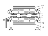
- the range of the magnetic force of the magnet 7 and the apparatus-side magnet 12 extends to the outside in the radial direction of the magnet 7 and the apparatus-side magnet 12 respectively. spread. Therefore, when the detection unit 33 for detecting the magnetic force is appropriately disposed outside the magnet 7 or the apparatus-side magnet 12 in the radial direction, the clutch unit 8 of the stirrer 6 operates and the clutch unit 8 is disconnected. That is, it can be determined that the stirrer 6 is in a loaded state.
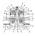
- FIG. 12 is a cross-sectional view taken along the line III-III in FIG. 13 and FIG. 14 are cross-sectional views when the magnetic gap is G1, which is enlarged for the portion B in FIG. 12, and are cross-sectional views when the magnetic gap is G2, which is enlarged for the portion B in FIG.
- a detection unit 33 is provided in the main body 1 (see FIG. 12) and in the vicinity of the apparatus-side magnet 12.
- the detection unit 33 is configured by, for example, a magnetic sensor that is a Hall element or a magnetoresistive element, and detects a change in the state of the rotating magnetic field.
- the detection unit 33 detects a change in the state of the rotating magnetic field by detecting magnetic coupling between the magnet 7 of the stirrer 6 and the apparatus-side magnet 12 of the magnetic field generation unit 11.
- the detection part 33 detects the change of the rotation state of the stirring body 6.
- the detection unit 33 detects magnetic coupling by detecting a change in the flow of magnetic force between the magnet 7 and the apparatus-side magnet 12.
- the detection unit 33 may be provided outside the device-side magnet 12 in the radial direction about the rotation center of the device-side magnet 12 and at a position facing the device-side magnet 12. And the change of the flow of the magnetic force in the outer side of the apparatus side magnet 12 may be detected by the detection part 33 arrange
- the detection part 33 can detect the coupling state between magnets using magnetic force conversion elements, such as a magnetic sensor, it can avoid that it becomes a complicated structure and an apparatus enlarges.
- the detection unit 33 may be a mechanical detection unit that combines a magnetic body and a switching element, such as a microswitch having an on / off lever formed of a magnetic body.
- FIG. 15 is a cross-sectional view showing the flow of magnetic force in the magnetic coupling when the magnetic gap is G1.
- FIG. 15 shows a state where the stirring body 6 is set in the container 2.
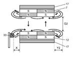
- FIG. 16 is a cross-sectional view showing the flow of magnetic force in the magnetic coupling when the magnetic gap is G2 in the configuration having the clutch portion.
- FIG. 16 shows a state in which the magnetic gap between the magnet 7 and the apparatus-side magnet 12 is expanded by the operation of the clutch unit 8.
- FIG. 15 shows a state where the clutch is connected and the food to be cooked can be stirred. That is, a large attractive force acts between the magnet 7 and the apparatus-side magnet 12, and these magnets are in a state of being strongly magnetically coupled. At this time, the flow of magnetic force between the magnets is concentrated between the magnetically coupled surfaces as indicated by the arrows in the figure. And the range (diameter distance Y) where the magnetic force flow exists on the radially outer side of the apparatus side magnet 12 is Y1, and is limited to the vicinity of the side surface of the magnet 7 and the apparatus side magnet 12 on the radially outer side. .
- the distance X between the detection unit 33 and the radially outer side surface of the apparatus-side magnet 12 is set to X> Y1. For this reason, in the state shown in FIG. 15, the detection part 33 does not detect magnetic force, or even if it detects, it is a trace amount.
- the magnetic gap between the magnets 7 between the magnet 7 and the apparatus-side magnet 12 increases to G2, as shown in FIG. . That is, the magnetic coupling between the magnet 7 and the apparatus-side magnet 12 is weakened. At this time, the flow of magnetic force between the magnet 7 and the apparatus-side magnet 12 decreases. On the other hand, in the magnet 7 and the apparatus-side magnet 12, the flow of magnetic force increases between adjacent magnets having different polarities, or between the magnets having different polarities.
- the detection unit 33 can detect the magnetic force by setting the distance X so that Y1 ⁇ X ⁇ Y2. That is, the detection unit 33 can detect a change in the flow of magnetic force between the magnet 7 and the apparatus-side magnet 12.
- the detection unit 33 can determine whether the clutch unit 8 is operating or not by detecting a change in the range in which the magnetic force flow exists outside the device-side magnet 12 in the radial direction. . That is, the rotation stop of the stirring body 6 can be detected.
- the rotation number M may be in the range of 1 to 2.
- the control unit 50 when the detection unit 33 detects a change in the flow of magnetic force, the control unit 50 outputs a signal for switching the rotation direction of the rotating magnetic field to the reverse direction to the magnetic field generation unit 11. As a result, the control unit 50 reversely rotates the agitator 6 through the apparatus-side magnet 12 and the magnet 7, for example, once or twice. Thereafter, the control unit 50 controls the magnetic field generation unit 11 to perform a normal stirring operation, that is, to rotate the rotating magnetic field N times in the forward direction and M times in the reverse direction.
- the number of rotations for reversely rotating the stirring member 6 when the detection unit 33 detects a change in the flow of magnetic force is set to 1 to 2.
- FIG. 17 is a cross-sectional view showing the flow of magnetic force in a magnetic coupling when a repulsive force is acting between magnets in a configuration having no clutch portion.
- FIG. 17 shows a state where the rotation of the magnet 7 is stopped, and the same polarity of the magnet 7 and the apparatus-side magnet 12 face each other. While the magnet 7 is stopped by applying a load to the stirrer 6, the apparatus-side magnet 12 continues to rotate, and thus the timing at which the same poles face each other is generated.
- the clutch portion 8 since the clutch portion 8 is not provided, the magnetic gap between the magnet 7 and the apparatus-side magnet 12 is always constant and is the same G1 as in FIG. 15.
- the range (diameter distance Y) in which the magnetic force flow exists outside the device-side magnet 12 in the radial direction is Y3, and Y1 ⁇ Y3.
- the detection unit 33 detects a change in the flow of magnetic force in the magnetic coupling between the magnet 7 and the apparatus-side magnet 12. be able to.
- the rotational torque (T) increases as the deviation of the magnetic pole between the magnets, that is, the rotation deviation angle increases. . Then, when the rotational torque exceeds the maximum value, step-out occurs.
- FIG. 18 is a diagram schematically showing the rotational deviation angle of the magnetic coupling and the force acting on the magnet, and the four-pole magnet between the apparatus-side magnet 12 and the magnet 7 used in the present embodiment. In the coupling configuration, the change in magnetic coupling with the rotational deviation angle is shown.
- FIG. 18 is a view of the magnet 7 and the apparatus-side magnet 12 as viewed from below, and the outer diameter of the magnet 7 is set to the outer diameter of the apparatus-side magnet 12 so that the positional relationship between the magnets can be easily explained. It is shown larger.
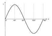
- FIG. 19 is a diagram showing the correlation between the rotational deviation angle ⁇ of the magnetic coupling and the rotational torque T.
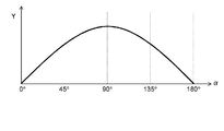
- FIG. 20 is a diagram showing a correlation between the rotational deviation angle ⁇ of the magnetic coupling and the range (radial distance Y) where the magnetic force flows on the radially outer side of the apparatus-side magnet.
- the rotational torque T is 0 when the rotational deviation angle ⁇ is 0 °, and the rotational torque T increases as the rotational deviation angle ⁇ increases.
- the rotational torque T is maximized.
- Rotational torque T is generated by the action of attractive force F1 and repulsive force F2 acting between magnet 7 and device-side magnet 12 in a state where device-side magnet 12 that is the drive-side magnet is rotating.
- the magnetic pole N1b receives a repulsive force F2 (thick line arrow) from the magnetic pole N1a at the same time it receives the attractive force F1 (broken line arrow) from the magnetic pole S1a. Accordingly, the rotational torque T increases as the repulsive force F2 increases.
- the rotational torque T changes as shown in FIG. 19 as the rotational deviation angle ⁇ changes. Specifically, as the rotational deviation angle ⁇ increases from 0 ° to 180 °, the rotational torque T changes as a sinusoidal curve with 180 ° as one cycle.
- the range in which the magnetic force flows outside in the radial direction (the radial distance Y) changes with the rotational deviation angle ⁇ as shown in the schematic diagram of FIG. To do.
- the distance Y changes as shown in FIG. 20 as the rotational deviation angle ⁇ changes. Specifically, as the rotational deviation angle ⁇ increases from 0 ° to 180 °, the distance Y changes as a sinusoidal curve having a half cycle of 180 °. That is, the distance Y is 0 when the rotation deviation angle ⁇ is 0 ° and 180 °. The distance Y becomes maximum when the rotational deviation angle ⁇ is 90 °.
- the detection unit 33 by arranging the detection unit 33 so that the distance X between the detection unit 33 and the apparatus-side magnet 12 is equal to or less than the maximum value of the distance Y and detecting a change in the magnetic force flow, Can be detected in advance.
- the food to be cooked stored in the container can be stirred while being heated. Therefore, for example, even in stewed cooking with a large load, such as curry for several dishes, it is possible to suppress scorching and uneven heating without periodic stirring with a rice scoop or the like.
- the heating and stirring cooker according to the present embodiment stirs the object to be cooked by rotating the stirring body by combining the forward rotation direction and the reverse rotation direction at different ratios. Therefore, since the rotational force of the stirring body can be applied to the object to be cooked from the direction opposite to the normal rotation direction, the object to be cooked is biased and the load on the stirring body is increased. The food to be cooked can be agitated while avoiding it.
- the agitator stops in the reverse direction by rotating the agitator without being operated by the user. It is possible to prevent this from happening, or to escape from the state where the stirring body is stopped. Therefore, stirring of a to-be-cooked object can be continued.
- the overload state can be released by combining the rotation in the reverse rotation direction, a large torque is unnecessary, and the torque of the stirring body can be set low. Accordingly, it is possible to suppress the cooking of the food to be cooked due to over stirring. Thereby, the heating stirring cooker which has the outstanding stirring performance can be provided. Furthermore, since a large torque is not required, the stirrer and the heating and stirring cooker can be reduced in size and weight, and the handleability is excellent.
- the state of the stirring body can be detected by having the detection unit. Further, the overload state of the stirring body can be released by switching the rotation direction of the stirring body to the reverse rotation based on the detection result.
- the user does not need to open and monitor the lid of the heating and stirring cooker until the cooking is completed, because the user is afraid that cooking is not performed properly and fails to cook. That is, the user only has to put the food to be cooked in advance at the start of cooking, and does not take time until cooking is completed.
- the content of the present disclosure may be applied to a cooker in which a lid is locked during cooking, a cooker in which an operation unit and a display unit are provided on the lid, a cooker with a timer reservation, and the like.
- each component demonstrated above it can select suitably and it combines so that there may exist the effect of this indication, or can employ
- the heating unit is not limited to a resistance heater, and heating means such as induction heating, steam, hot air, and radiant heating may be used.
- the configuration in which the stirrer is provided with the clutch portion is mainly described.
- the lock suppression mechanism that suppresses the rotation of the stirrer from being stopped due to the load and becoming unrotatable (locked state).
- the agitator may have no clutch portion.
- the number of rotations may be determined and switched in the forward rotation direction and the reverse rotation direction in accordance with the amount and type of the object to be cooked.
- the heating and stirring cooker of the present disclosure can be applied to cooking devices such as an electric pressure cooker and a multi-cooker because the stirring performance is improved and the usability is improved.
Landscapes
- Engineering & Computer Science (AREA)
- Food Science & Technology (AREA)
- Mechanical Engineering (AREA)
- Chemical & Material Sciences (AREA)
- Chemical Kinetics & Catalysis (AREA)
- Cookers (AREA)
- Food-Manufacturing Devices (AREA)
Abstract
加熱撹拌調理器(100)は、本体(1)と、本体(1)内に配置され、被調理物が収納される容器(2)と、容器(2)内において容器(2)に対して着脱可能に配置される撹拌体(6)であって、容器(2)内の被調理物を撹拌する羽根(10)と、撹拌体(6)が容器(2)内に配置された状態において容器(2)の内底部に対向する位置に配置された磁石(7)と、を有する撹拌体(6)と、本体(1)内に配置され、回転磁界を発生し、回転磁界による回転力を磁石(7)に作用させる磁界発生部(11)と、本体(1)内に配置され、磁界発生部(11)を制御する制御部(50)と、を備える。そして、制御部(50)は、回転磁界の回転方向が、正回転方向と前記正回転方向と逆の逆回転方向との間で切り替わるよう、かつ、逆回転方向への回転回数Mが、正回転方向への回転回数Nよりも少なくなるよう、磁界発生部(11)を制御するよう構成される。
Description
本開示は、加熱される容器と、容器内に収容された被調理物を撹拌するための撹拌体とを備えた加熱撹拌調理器に関する。具体的には、容器内に配置され、容器の外部からの回転磁界を受けて回転する撹拌体を備えた加熱撹拌調理器に関する。
従来から、誘導加熱調理器に備えられたコイルから発生する磁界によって、コイルの上方に載置された鍋を誘導加熱するとともに、永久磁石又は着磁体を有した回転翼の回転をおこなう回転加熱調理器が提案されている(例えば、特許文献1参照)。
図21は、特許文献1に記載された従来の回転加熱調理器を示す断面図である。回転加熱調理器の本体101には、複数部に分割され、インバータ103に接続されたコイル104が設けられている。複数部に分割されたコイル104は、インバータ103の出力に応じて、高周波磁界もしくは低周波磁界、又はこれらの混合磁界を発生する。これにより、非磁性金属で形成された鍋105が誘導加熱されるとともに、コイル104が発生する回転磁界によって、鍋105内部に配置され、内部に磁石106を備えた回転翼107の回転が行われる。
また、加熱される炊飯用の鍋と、鍋の内部に設けられた撹拌体とを有し、撹拌体の被駆動側磁石に対し、炊飯器本体の回転駆動装置で発生させた回転磁界との磁気カップリングにより撹拌体を回転駆動する電気炊飯器が提案されている(例えば、特許文献2参照)。
図22は、特許文献2に記載された従来の電気炊飯器を示す断面図である。撹拌モータ204が駆動されることで、駆動側の磁石205が回転磁界を発生させる。そして、回転磁界と撹拌翼201との磁気カップリングによって非接触で撹拌翼201が回転駆動される。従って、回転駆動装置202が炊飯用の鍋203を貫通せず、貫通箇所から水漏れが発生することはない。
また、磁気カップリングの手法を用いた種々の撹拌装置において、撹拌体の回転動作を検知する手段として、例えば特許文献3~5の構成が提案されている。
特許文献3の撹拌装置の撹拌部材には、撹拌部材の回転中心から外れた位置に永久磁石で構成され、撹拌部材と一体となって回転する検知子が設けられている。また、撹拌装置は、検知子の磁気に反応して検知子の位置を検出するセンサを有する。これにより、撹拌部材の回転数を検出し、検出結果に基づいて撹拌部材の回転数が制御される。
特許文献4の撹拌装置については、容器の下方において、駆動磁石から磁気遮蔽され、撹拌用回転子の磁気を検出する複数の磁気検出センサが配置されている。複数の磁気検出センサは、並列回路によって結ばれている。これにより、容器内において撹拌用回転子が離脱したことを検出することができ、駆動磁石を一時低速に回転させる等の制御をすることで、撹拌用回転子を元の位置に戻すものである。
図23は、特許文献5に記載された従来の撹拌装置を示す断面図である。図23に示す撹拌装置は、容器301の内部に磁気動作体302が配置され、容器301の下方に、磁気動作体302を回転させるための駆動装置303が配置されている。また、駆動装置303は力センサ304によって支持されている。そして、力センサ304が駆動装置303の見掛け重量を継続的にモニターすることにより、磁気動作体302と駆動装置303との間の磁力の大きさを検知する。これにより、使用者が撹拌装置の容器301の中を確認することなく、磁気動作体302が連動しなくなり始めたこと、又は、離脱したことを検出することができる。
しかしながら、加熱撹拌調理器において、磁気カップリングを用いた従来のような撹拌装置を利用して、被調理物を撹拌するための大きなトルクを得ようとすると、装置が大型化してしまうという課題がある。また、加熱撹拌調理器において、使用者の使い勝手を更に向上させる観点において、未だ改善の余地がある。
本開示は、装置の大型化を抑制するとともに、被調理物を効率的に撹拌し、使い勝手を更に向上した加熱撹拌調理器を提供する。
具体的には、加熱撹拌調理器は、本体と、本体内に配置され、被調理物が収納される容器と、容器内において容器に対して着脱可能に配置される撹拌体であって、容器内の被調理物を撹拌する羽根と、撹拌体が容器内に配置された状態において容器の内底部に対向する位置に配置された磁石と、を有する撹拌体と、本体内に配置され、回転磁界を発生し、回転磁界による回転力を磁石に作用させる磁界発生部と、本体内に配置され、磁界発生部を制御する制御部と、を備える。そして、制御部は、回転磁界の回転方向が、正回転方向と前記正回転方向と逆の逆回転方向との間で切り替わるよう、かつ、逆回転方向への回転回数Mが、正回転方向への回転回数Nよりも少なくなるように、磁界発生部を制御するよう構成される。
これにより、撹拌体を正回転方向と逆回転方向とを異なる割合で組み合わせて回転させて被調理物を撹拌することで、被調理物に対し正回転方向の回転とは反対の向きからも撹拌体の回転力を作用させることができ、被調理物の偏りによる撹拌体にかかる負荷の増大要因を解除しつつ撹拌を行うことができる。さらに、撹拌体が過負荷によって減速、又は、停止する場合でも、撹拌体の逆回転方向の回転を組み合わせているので、人手を介さずにこの状態から脱出し、被調理物の撹拌を継続することができる。
(本開示の基礎となった知見)
本発明者らは、磁気カップリングを用いた加熱撹拌調理器について、大型化を抑制しつつ、使用者の使い勝手を更に向上させるために、鋭意検討した結果、以下の知見を得た。
本発明者らは、磁気カップリングを用いた加熱撹拌調理器について、大型化を抑制しつつ、使用者の使い勝手を更に向上させるために、鋭意検討した結果、以下の知見を得た。
従来の加熱撹拌調理器において実際に調理行うと、次のような事象が発生することがわかった。
例えば、固形物を主とする被調理物を撹拌する場合には、被調理物のサイズ、大きさ、硬さなどは一様ではない。従って、撹拌体にかかる負荷は、被調理物の相互の重なり方、容器との接触のしかたなどの変化にともない、撹拌調理中に刻々と変動する。
また、撹拌体にかかる負荷は、被調理物が加熱されるのにともなって、被調理物について硬さの変化、水分の移動、蒸発などが発生することでも刻々と変化する。
そして、例えば、撹拌体の羽根部の回転動作によって被調理物の一部が羽根部と容器の内周部との間に挟まると、挟まった被調理物が羽根部に対する抵抗となって、撹拌体の回転負荷が増大する。このとき、撹拌体の回転負荷が駆動トルクを上回ると撹拌体は回転不能の状態(ロック状態)となる。そして、この状態で加熱が継続されると、被調理物の加熱ムラ、焦げ付き等が発生して調理の失敗につながってしまう。
このため、従来の撹拌加熱調理器を使用する場合、使用者は撹拌体が停止していないかを調理中に時々監視する必要がある。また、撹拌体が停止している場合には、負荷の増大要因を取り除く手間が生じてしまう。
ここで、上述のような撹拌体にかかる負荷の変動に対応するために、十分大きなトルクを発生させて撹拌しようとすると、装置が大型化してしまう。つまり、撹拌のための駆動力を発生させるモータ、その駆動力を撹拌体に伝達させる動力伝達手段、モータに電力を供給する電源などが大型化するとともに、装置の重量も増加してしまう。
例えば、特許文献1に記載の撹拌装置の場合、コイルと回転翼に設けられた永久磁石との間には、鍋を載置する載置板の厚み及び鍋の厚みが存在するために、大きな磁気ギャップが存在する。実際にはこの磁気ギャップは5mmから15mm程度となる。そして、磁気ギャップが大きい程、磁気結合は弱まる。このため、大きな回転トルクを確保するためには、コイルから発生される磁束と永久磁石で形成される磁束とが十分に鎖交する構成が必要となり、機器が大型化してしまう。
また、加熱中の被調理物を大きなトルクで撹拌することは、被調理物の煮崩れ等の要因となり、調理の出来栄えを損ねることにつながる。
また、逆に、被調理物から受ける抵抗が低減するよう構成された羽根部で撹拌すると、被調理物に対する撹拌作用が限定されてしまうため、調理における撹拌効果は小さくなってしまう。
なお、調理における撹拌効果とは、例えば、水分が少なく対流を期待できないような固形物中心の被調理物の加熱調理、水分が蒸発することで焦げ付きなどの心配のある加熱調理等であっても、加熱ムラ及び焦げ付きを抑制するものである。
通常の鍋での調理においては、使用者自身が箸、ヘラなどの調理具を用いて、被調理物を裏返したり上下入れ替えたり集めたり散らばせたりして、被調理物が均一に加熱されるように断続的又は連続的に操作を行う。加熱撹拌調理器においては、これらと同等の効果を得るために、撹拌体の羽根部を被調理物に物理的に作用させる。
なお、加熱調理における加熱ムラ及び焦げ付きの要因としては、容器を加熱するヒータ等の加熱手段の配置、熱伝導の差、容器内の被調理物の位置や対流の有無、さらには被調理物の疎密などによる熱容量の大小等が複雑に関係している。このため、形及び大きさが一定でない、不揃いにカットされた被調理物について、加熱ムラ及び焦げ付きを抑制するためには、容器内での配置位置の相互の入れ替わり、被調理物と容器とが接触する接触面の変更等を促進することで、被調理物が一定箇所に留まった状態で加熱されないようにすることが必要となる。
従って、発明者らは、被調理物を効率よく撹拌できれば、装置が大型化することなく、使い勝手を向上できると考えた。
また、従来の撹拌装置においては、撹拌体が回転不能な状態になっても、駆動側の磁石は回転し続ける。このため、撹拌体と駆動側装置との間で対向する磁石の極性が同極に近づくことにより、磁気カップリング間の反発力が増大するため、撹拌体が回転磁界の回転から脱調し、回転中心から離脱してしまう。
このような状態を回避するためには、撹拌体の動作を検出することが一つの方法である。
例えば、特許文献3及び特許文献4の構成の場合、撹拌体が離脱したことを、離脱後に検知できる構成である。しかし、加熱撹拌調理器の場合、一旦撹拌体が離脱してしまうと、被調理物が抵抗となるため撹拌体を元の位置に戻すことは困難である。
従って、発明者らは、撹拌体が離脱する前に撹拌体が離脱する可能性を検知する、又は、撹拌体が離脱する可能性を低減することができれば、撹拌動作を継続して使用者の使い勝手を向上することができると想到した。
なお、特許文献5の構成の場合、駆動装置に対して回転軸方向(上下方向)に掛かる見掛け上の重量は、磁気カップリング間において生じる反発力によって変化する。従って、撹拌体が脱調する直前を検出することが可能ではある。しかし、駆動装置が上下に移動可能にする支持構成、及び、駆動装置の重量を検出する構成が必要であり、構造が複雑で機器が大型化してしまう。
これらの新規な知見に基づき、本発明者らは、以下の開示に至った。
本開示の一態様に係る加熱撹拌調理器は、本体と、本体内に配置され、被調理物が収納される容器と、容器内において容器に対して着脱可能に配置される撹拌体であって、容器内の被調理物を撹拌する羽根と、撹拌体が容器内に配置された状態において容器の内底部に対向する位置に配置された磁石と、を有する撹拌体と、本体内に配置され、回転磁界を発生し、回転磁界による回転力を磁石に作用させる磁界発生部と、本体内に配置され、磁界発生部を制御する制御部と、を備える。そして、制御部は、回転磁界の回転方向が、正回転方向と前記正回転方向と逆の逆回転方向との間で切り替わるよう、かつ、逆回転方向への回転回数Mが、正回転方向への回転回数Nよりも少なくなるように、磁界発生部を制御するよう構成されるものである。
このような構成により、回転磁界の回転方向が、正回転方向と正回転方向と逆の逆回転方向との間で切り替わるよう、磁界発生部が制御され、逆回転方向への回転回数Mは、正回転方向への回転回数Nよりも少ないことから、回転負荷の増大要因を取り除いて撹拌を継続することができる。従って、被調理物を効率的に撹拌できるため、装置の大型化を抑制することができる。これにより、加熱撹拌調理器の使い勝手を向上することができる。
本開示の他の一態様に係る加熱撹拌調理器は、制御部は、回転磁界が正回転方向及び逆回転方向について予め定められた設定回転回数回転したとき、及び、撹拌体の回転状態の変化を検知したときの少なくともいずれかの場合に、回転磁界の回転方向を切り替えるよう構成されていてもよい。
このような構成により、回転磁界が正回転方向及び逆回転方向について予め定められた設定回転回数回転したとき、及び、回転磁界の状態の変化を検知したときの少なくともいずれかの場合に、回転磁界の回転方向を切り替えるため、負荷が増大するのを抑制し、又は、撹拌体が停止した場合であっても、効率よく回転負荷の増大要因を取り除いて撹拌を継続することができる。
本開示の他の一態様に係る加熱撹拌調理器は、回転磁界が正回転方向及び逆回転方向について予め定められた設定回転回数回転したときに回転磁界の回転方向が切り替えられる場合において、回転回数Nに対する回転回数Mの比率は、0.1~0.9の範囲であってもよい。
このような構成により、負荷の増大を抑制しつつ、正回転方向への回転回数を多くして、効率よく被調理物を撹拌することができる。
本開示の他の一態様に係る加熱撹拌調理器は、回転磁界が正回転方向及び逆回転方向について予め定められた設定回転回数回転したときに回転磁界の回転方向が切り替えられる場合において、回転回数Mは、1~2の範囲であってもよい。
このような構成により、逆回転方向への回転回数を1~2回とすることで、負荷の増大の抑制が見込める範囲内で逆回転方向への回転回数を小さくし、効率よく被調理物を撹拌することができる。
本開示の他の一態様に係る加熱撹拌調理器は、磁界発生部は、磁石と対向する位置に配置された装置側磁石と、装置側磁石を回転させる回転駆動部と、を有し、さらに、本体内に配置され、磁石と装置側磁石との間の磁気結合の状態を検知することで、撹拌体の回転状態の変化を検知する検出部を、装置側磁石の近傍に備えていてもよい。
このような構成により、簡素な構成で撹拌体の回転状態の変化を検知することができ、撹拌体の脱調又は回転中心からの離脱を検出することができる。
本開示の他の一態様に係る加熱撹拌調理器は、検出部は、磁石と装置側磁石との間の磁気結合における磁力の流れの変化を検知してもよい。
このような構成により、磁気結合における磁力の流れの変化を利用して、簡素な構成で撹拌体の回転状態の変化を検知することができる。
本開示の他の一態様に係る加熱撹拌調理器は、制御部は、回転磁界が正回転方向へ回転している場合において、検出部が磁石と装置側磁石との間の磁気結合における磁力の流れの変化を検知したとき、回転磁界の回転方向を逆回転方向に切り替えるよう構成されていてもよい。
このような構成により、撹拌体の回転が停止した場合であっても、これを検出するとともに、逆回転方向に回転させることで、撹拌体の回転の停止要因となった被調理物から離れる方向に撹拌体を動作させ、撹拌体が停止した状態から脱出することができる。
本開示の他の一態様に係る加熱撹拌調理器は、回転磁界の回転方向が逆回転方向に切り替えられた後の逆回転方向への回転回数Mは2以下であり、回転磁界がM回転したときに、回転磁界の回転方向が正回転方向に切り替えられてもよい。
このような構成により、撹拌体が停止する要因となる被調理物の塊を崩し、及び、散らすことができるとともに、再度正回転方向に回転させることで撹拌を継続することができる。
本開示の他の一態様に係る加熱撹拌調理器は、検出部は、装置側磁石の回転中心についての半径方向における装置側磁石の外側であって、装置側磁石に対向する位置に設けられ、装置側磁石の外側における磁力の流れの変化を検知してもよい。
このような構成により、簡素な構成で磁力の流れの変化を検知することができる。
本開示の他の一態様に係る加熱撹拌調理器は、羽根は、羽根が正回転方向へ回転しているときに被調理物を寄せ集め、かつ、羽根が逆回転方向へ回転しているときに寄せ集められた被調理物を崩すよう構成されていてもよい。
このような構成により、効率よく被調理物の撹拌し、回転負荷の増大要因となった被調理物の塊を崩すことができる。
以下、本発明の実施の形態について、図面を参照しながら説明する。なお、この実施の形態によって本発明が限定されるものではない。
(実施の形態)
[1.加熱撹拌調理器の全体構成]
図1は、本開示の実施の形態における加熱撹拌調理器の全体を示す斜視図である。図2は、同実施の形態における加熱撹拌調理器の蓋体を外した状態を示す平面図である。図3は、図2のIII-III切断線における縦断面図である。また、図4及び図5は、それぞれ、図3のA部分について拡大した、磁気ギャップがG1のときの断面図、図3のA部分について拡大した、磁気ギャップがG2のときの断面図である。
[1.加熱撹拌調理器の全体構成]
図1は、本開示の実施の形態における加熱撹拌調理器の全体を示す斜視図である。図2は、同実施の形態における加熱撹拌調理器の蓋体を外した状態を示す平面図である。図3は、図2のIII-III切断線における縦断面図である。また、図4及び図5は、それぞれ、図3のA部分について拡大した、磁気ギャップがG1のときの断面図、図3のA部分について拡大した、磁気ギャップがG2のときの断面図である。
図1に示すように、加熱撹拌調理器100は、被調理物等が内部に収納される本体1と、本体1を覆う蓋部5と、を有する。
また、図2に示すように、本体1の内部には、容器2が配置されている。容器2は、本体1の容器収納部3に収納されている。
容器2は、内底部と内周部とを備え、上方に開口を有する。被調理物は、容器2に収納されて調理される。内底部及び内周部はそれぞれ、容器2の内面である内周面及び内底面を構成している。
本体1は、内壁と外壁とを備え、上方に開口を有する。容器収納部3は、本体1の内壁によって形成されている。
図3に示すように、容器収納部3の底部分には、加熱手段であるヒータ4が配置されている。ヒータ4は、容器2の下面と接することで、容器2に熱を伝達する。ヒータ4は、平面視においてリング状の形状である。また、ヒータ4は、容器収納部3に容器2が収納されたときに容器2の下面に沿うように配置されている。容器2は、ヒータ4からの熱を受けて発熱する。
また、本体1の上方には、本体1の開口を覆う蓋部5が配置されている。蓋部5は、本体1に対して上下方向に回動可能となるように、本体1に取り付けられている。
容器2内に撹拌体6が配置される。撹拌体6は、収納部9と、収納部9の周囲に形成された羽根10とを備える。収納部9の内部には、永久磁石で構成された磁石7とクラッチ部8とが収納される。
撹拌体6は、容器2内において、容器2の内底部に対して着脱可能に配置される。羽根10は、撹拌体6の回転に伴って回転し、容器2内の被調理物を撹拌する。
図4に示すように、磁石7は、撹拌体6が容器2に配置された状態において、容器2の内底部に対向する位置に配置される。また、磁石7は、収納部9の外部から回転磁界によるトルク(回転力)を受けることが可能である。
本体1の内部には、回転磁界を発生させる磁界発生部11が配置されている。
すなわち、磁界発生部11は、容器2の内底部の外側に位置し、撹拌体6の磁石7と対向するように配置される。
磁界発生部11は、カップリング部13と、回転駆動部であるモータ14とを有して構成される。モータ14は、カップリング部13に連結される。
カップリング部13には、永久磁石で構成された装置側磁石12が収納されている。装置側磁石12は、磁石7の磁界に対向するように配置されている。
なお、装置側磁石12は、カップリング部13の嵌め合い部において、カップリング部13と嵌合され、カップリング部13内に収納されている。従って、モータ14の駆動力がカップリング部13に伝達されると、カップリング部13と一緒に装置側磁石12が回転する。これによって、回転磁界が発生する。
図3に示すように、本体1内には、制御部50が配置されている。
制御部50は、モータ14の回転を制御して、装置側磁石12の回転を制御する。これにより、回転磁界の回転(例えば、回転方向、回転回数、回転速度等)が制御される。
カップリング部13は、ヒータ4に形成された中央開口を貫通するように配置されている。カップリング部13の上端と容器2の下面との間には、スペーサ部材15が配置されている。スペーサ部材15は、カップリング部13の上部に取り付けられている。カップリング部13の上端は、スペーサ部材15によって、容器2の下面から約1mm下方に位置するよう配置されている。
なお、容器2の内周部の一部には、容器2の中心方向に向かって約6mm突出し、横断面形状が湾曲した形状の邪魔部16(図2参照)が設けられてもよい。邪魔部16は、被調理物に対する撹拌性能を向上させることができる。
[2.撹拌体の詳細構成]
次に、撹拌体6の詳細構成について説明する。
次に、撹拌体6の詳細構成について説明する。
撹拌体6は、収納部9を有する(図4参照)。そして、収納部9には、磁石7と、クラッチ部8と、が収納されている。
図6A~図6Cは、それぞれ、実施の形態における撹拌体の磁石を示す底面図、同実施の形態における撹拌体の磁石を示す側面図、同実施の形態における撹拌体の磁石を示す平面図である。
図6Aに示すように、磁石7は、リング状に構成されている。さらに、図6Bに示すように、磁石7の上方には、磁性金属板17が配置されている。磁性金属板17は、例えば磁石7に接着されて取り付けられている。図6Cに示すように、磁性金属板17は、中央部分に開口部18が形成されている。磁性金属板17は、磁石7が収納部9に収納された状態において、磁石7からの磁力が上方へ漏洩するのを抑制する。
すなわち、磁性金属板17は、磁石7に対して外部から回転力が付与される側とは反対側に配置されている。
また、図6Aに示すように、磁石7は、4極の磁極がN/S/N/Sの順に配置されている。
なお、開口部18は、開口部18の外縁において、直線部を少なくとも1箇所有して形成されていてもよい。
図7A及び図7Bは、それぞれ、実施の形態における撹拌体を下方から見た分解斜視図、同実施の形態における撹拌体を上方から見た分解斜視図である。
クラッチ部8(図3参照)は、図7A及び図7Bに示すクラッチ爪部19と、柱状部21と、クラッチ係合部22と、を有して構成されている。
クラッチ爪部19は、略円筒形状の基部20aと、基部20aの内周部から突出し、内周部に沿うように形成された、爪20b及び平坦部20cとを有する。爪20bは、内周部側から突出する凸形状になっている。
クラッチ爪部19は、クラッチ爪部19の基部20aが、磁性金属板17の開口部18に嵌合される。これにより、磁石7の回転に伴い、クラッチ爪部19が回転する。
爪20bは、基部20aの中心側から見たときの形状が、略台形状で、かつ、上底よりも下底の長さが短くなるように構成されている。これにより、爪20bの左右の側面は、下底から上底の方向に向かって傾斜する傾斜面を構成する。
柱状部21は、収納部9の回転中心に配置されている。柱状部21が、磁石7及びクラッチ爪部19を貫通することで、磁石7及びクラッチ爪部19が柱状部21に取り付けられている。これにより、磁石7及びクラッチ爪部19は、柱状部21に対して上下に昇降することができるとともに、柱状部21を中心として回転可能となっている。換言すれば、磁石7は、収納部9内において柱状部21の高さ方向に移動可能に収納されている。
クラッチ係合部22は、基部22aと、係合部23と、基部22aの上端面によって形成されたスライド部28と、を有する。また、クラッチ係合部22は、クラッチ爪部19と対向するように、クラッチ爪部19の下方に配置されている。クラッチ係合部22は略円筒形状であり、柱状部21によって貫通された状態で収納部9の下部付近に配置されている。クラッチ係合部22は柱状部21に固定されている。
係合部23は、基部22aの一部を上方から切り欠くことで凹形状に形成されている。係合部23の外形形状は、クラッチ爪部19の爪20bの外形形状に対応している。すなわち、係合部23は、爪20bの左右の傾斜面の形状に対応する傾斜面を有するように形成されている。係合部23の大きさは、爪20bの大きさより若干大きい。これにより、爪20bが係合部23に確実に嵌まり込む。
なお、図4に示すように、柱状部21の上部は、収納部9内に磁石7等が収納された状態において、締結手段等によって固定部32に固定されている。
また、柱状部21の下部の内部には、回転中心部に凹部が形成されている。柱状部21の凹部には、シャフト部26(図4参照)が配置されている。シャフト部26は、図4に示すように、シャフト26aと、軸受用のブッシュ24と、シャフト26aと一体に構成された略円板状の受け部25と、を備えている。
撹拌体6が容器2に配置される際は、シャフト部26の受け部25が、容器2の内底部に接触して内底部に載置された状態となる。そして、撹拌体6の羽根10及び収納部9は、シャフト部26を中心に回転する(図3参照)。
なお、図5に示すシャフト26aは、ブッシュ24によって撹拌体6の回転は伝達されない。従って、受け部25及びシャフト26aは、容器2の内底部に接触し、かつ、内底部に固定された状態のままほぼ回転しない。
また、後述の図8~図11に示すように、クラッチ爪部19の下方には、クラッチ爪部19に対して上方向に押圧力がかかるように、例えば圧縮コイルで構成された、バネ27が配置されている。バネ27は、クラッチ爪部19の基部20aと収納部9の底面との間に配置されている。バネ27は、磁石7が回転磁界による回転力を受ける側と反対側に向けて磁石7を付勢している。
図5は、クラッチ部8が切れており、磁気ギャップがG2となったときの状態を示している。なお、クラッチ部8が切れた状態とは、クラッチ爪部19の爪20bとクラッチ係合部22の係合部23(後述の図8参照)とが係合していない状態のことである。
バネ27によってクラッチ爪部19が押し上げられると、図5に示すように、磁石7及び磁性金属板17は収納部9の固定部32の直下にまで押し上げられる。バネ27の荷重(バネ係数)は、この状態において撹拌体6の収納部9の底面が磁性体の金属板上(例えば、鉄板上)に置かれた際に、磁石7の磁力によって金属板側に引き付けられる吸着力に対して1.2~1.5倍の力が磁石7にかかるように設定されている。
後述の図10に示すように、磁石7及び磁性金属板17が収納部9の固定部32の直下に位置した際、爪20bの下端は、スライド部28の面上を滑りながら摺動し、シャフト部26(図4参照)を中心に回転する。なお、スライド部28は、係合部23と連続して形成されている(図7B参照)。
また、図4及び図5に示すように、磁性金属体29が収納部9内の内壁に固定して取り付けられている。磁性金属体29は、平面視において撹拌体6のシャフト部26を中心としたリング状である。
磁性金属体29は、磁石7の外側であって、磁石7が固定部32の直下にあるときの磁石7の側面に対向する位置に配置されている(図5参照)。
なお、磁性金属体29の厚みは、1mm~3mmであってもよい。
磁性金属体29と磁石7との間には、0.5~3mmのクリアランスが設けられている。これにより、磁石7が収納部9内で昇降及び回転する際に、磁石7が磁性金属体29と接触することを回避できる。
一方、図4に示すように、磁石7が収納部9の下部に位置する際には、磁石7の大部分は、磁性金属体29と対向しない。
図8は、実施の形態における撹拌体の爪が係合部と係合した状態を示す断面図である。図9は、同実施の形態における撹拌体の爪が係合部の傾斜面を上昇している途中の状態を示す断面図である。また、図10は、同実施の形態における撹拌体の爪が係合部から外れるとともに、磁石が上昇した状態を示す断面図である。なお、このとき、撹拌体6の爪20bはスライド部28に載置された状態である。さらに、図11は、同実施の形態における撹拌体の爪が係合部の傾斜面を下降している途中の状態を示す断面図である。
図8に示す状態において、スライド部28(図9参照)は、クラッチ爪部19の平坦部20cを下方から保持する。
また、クラッチ係合部22の係合部23は、クラッチ爪部19の爪20bと接触する傾斜面30a,30bを左右に有する。撹拌体6が主に回転する正(右)回転方向で回転しているときは、爪20bは傾斜面30aと係合(接触)する。傾斜面30aの傾斜角度θ1(図9参照)は、回転平面に対して65°~85°に設定されている。
一方、撹拌体6が逆(左)回転方向で回転しているときは、爪20bは傾斜面30bと係合(接触)する。傾斜面30bの傾斜角度θ2(図11参照)は、回転平面に対して45°~75°に設定されている。
なお、撹拌体6の磁石7としては、ネオジウム焼結磁石、サマリウムコバルト磁石、Fe-Cr-Co系磁石、及びFe-Nd-B系のボンド磁石のうちのいずれかの磁石が用いられる。一方、磁界発生部11の装置側磁石12の磁石としては、ネオジウム焼結磁石が用いられる。また、磁石7は、撹拌体6を容器2から取り外した状態における撹拌体6の取り扱い易さを考慮し、装置側磁石12よりも吸着力等の磁気特性が低くなるように、材質及びサイズが設定されている。
[3.撹拌体の機能]
次に、撹拌体6の機能について説明する。
次に、撹拌体6の機能について説明する。
撹拌体6の磁石7には、磁界発生部11の装置側磁石12の回転動作が、容器2を介して非接触で伝達される。
図6Aに示すように、撹拌体6の内部に収納された磁石7は、N極及びS極が円周方向に交互に配置されてリング状に構成されている。
そして、磁石7と対向する位置において、カップリング部13の装置側磁石12も、N極及びS極が円周方向に交互に配置されている。
このような構成により、装置側磁石12が回転すると回転磁界が発生する。そして、磁石7には回転磁界による回転力(トルク)が作用する。これにより、磁石7は装置側磁石12の回転に伴って回転する。
すなわち、装置側磁石12が回転すると、磁石7及び装置側磁石12の対向する異極の磁石間に発生する吸引力、及び、これらの磁石と隣接する磁石7及び装置側磁石12の同極の磁石間に発生する反発力によって、磁石7は装置側磁石12と同期した状態で回転する。
なお、図2において実線矢印に示す時計方向Rの回転が、撹拌体6の正回転方向であり、破線矢印に示す反時計方向Lの回転が撹拌体6の逆回転方向である。
本実施の形態では、制御部50は、回転磁界の回転方向が、正回転方向と正回転方向と逆の逆回転方向との間で切り替わるように、磁界発生部11を制御する。そして、制御部50は、回転磁界を正回転方向にN回転させ、正回転方向と逆の逆回転方向にM回転させる。
制御部50は、回転磁界が正回転方向及び逆回転方向について予め定められた設定回転回数回転するように構成されていてもよい。また、制御部50は、回転磁界が正回転方向及び逆回転方向について予め定められた設定回転回数回転したときに、回転磁界の回転方向を切り替えるように構成されていてもよい。
そして、制御部50は、回転磁界が正回転方向及び逆回転方向について予め定められた設定回転回数回転したとき、及び、撹拌体6の回転磁界の状態の変化を検知したときの少なくともいずれかの場合に、回転磁界の回転方向を逆回転方向へ切り替える。また、制御部50は、回転磁界を逆回転方向へM回転させる。
なお、制御部50は、逆回転方向への回転回数Mが、正回転方向への回転回数Nよりも少なくなるよう、磁界発生部11を制御する。
これにより、磁石7が正回転方向にN回転し、クラッチ部8により回転力が伝達された撹拌体6の羽根10が、正回転方向にN回転する。
そして、回転磁界が正回転方向について予め定められた設定回転回数回転したとき、及び、撹拌体6の回転磁界の状態の変化を検知したときの少なくともいずれかの場合に、磁石7が逆回転方向にM回転し、クラッチ部8により回転力が伝達された撹拌体6の羽根10が、逆回転方向にM回転する。
これにより、撹拌体の正回転方向の回転とは被調理物への作用が異なるように逆回転方向の回転動作を組みあわせているので、被調理物に対して正回転方向の回転とは反対の方向からも撹拌体6の回転トルクを作用させることができる。従って、被調理物の偏り過ぎによる撹拌体6にかかる負荷の増大要因を効果的に解除しつつ撹拌を継続することができる。
また、図2に示すように、撹拌体6の羽根10は、羽根10の平面視において、正回転方向に向けて凸状に湾曲している。これにより、羽根10が正回転方向へ回転しているときに、被調理物が容器2内において、容器2の中心側から内周部側の方向に向かって寄せ集められる。また、羽根10が逆回転方向へ回転しているときに、正回転方向の回転により寄せ集められた被調理物が容器2の中心側に向かって崩される。
これにより、効率よく被調理物の撹拌し、回転負荷の増大要因となった被調理物の塊を崩すことができる。
また、回転磁界が正回転方向及び逆回転方向について予め定められた設定回転回数回転したときに回転磁界の回転方向が切り替えられる場合、正回転方向の回転回数Nに対する逆回転方向の回転回数Mの比率は、0.1から0.9の範囲に設定されていてもよい。すなわち、制御部50は、回転磁界が正回転方向へ回転する割合の方が逆回転方向へ回転する割合よりも大きくなるように、磁界発生部11を制御してもよい。
これにより、負荷の増大を抑制しつつ、効率よく被調理物を撹拌することができる。
また、制御部50は、回転磁界が正回転方向及び逆回転方向について予め定められた設定回転回数回転したときに回転磁界の回転方向が切り替えられる場合、逆回転方向への回転回数Mが1~2の範囲となるように磁界発生部11を制御してもよい。
これにより、撹拌体6を1回転以上、逆回転方向に回転させて、撹拌体6の停止の要因となった被調理物の塊を崩す、及び、散らすことができる。
本実施の形態では、正回転方向については2.5回、逆回転方向については1.25回というように、それぞれの回転方向について回転回数が予め設定されている。すなわち、正回転方向への回転回数Nに対する逆回転方向への回転回数Mの比率が0.5となるよう、制御部50が磁界発生部11を制御している。従って、磁石7から回転力が伝達されることによって撹拌体6は、正回転方向に2.5回回転し、その後逆回転方向に1.25回回転する。
そして、羽根10が逆回転方向に回転することで、正回転方向の回転により寄せ集められた被調理物は(容器2の中心側に向かって)崩される。これにより、加熱撹拌調理器100にかかる負荷の増大が抑制される。また、羽根10が逆回転方向に回転する割合に対して正回転方向に回転する割合が大きくなるように制御されることによって、容器2内における被調理物を効率的に撹拌することができる。
また、正回転方向への回転回数Nに対する逆回転方向への回転回数Mの比率は、撹拌体6の回転方向が切り替えられる際の羽根10の位置が、前回回転方向が切り替えられた際の羽根10の位置と同じにならないように設定されている。例えば、回転回数M,Nはそれぞれ整数とならないように設定される。これによって、正回転方向又は逆回転方向への回転の開始時と回転方向の切り替え時において、羽根10の位置が異なる位置となる。従って、偏りなく均一に被調理物を撹拌することができる。
撹拌体6による被調理物の撹拌作用について詳細に説明する。図2に示す撹拌体6が正回転方向に回転することにより、羽根10が被調理物を容器2内において中心側から内周部側の方向に向けて押し出す。このとき、被調理物は、容器2の内壁面又は邪魔部16から抵抗を受けることによって、羽根10を乗越える。すなわち、羽根10は、被調理物を押し出すとともに、被調理物を返すようにも作用する。従って、撹拌体6を正回転方向及び逆回転方向へ交互に回転させることで、被調理物を容器2内で散らしたり寄せ集めたりすることができる。また、被調理物の裏表を返すことができるため、ヒータ4の熱が容器2底面から被調理物全体に伝わるように加熱しながら撹拌調理を行うことができる。
なお、本実施の形態において、固形物を主とした被調理物の撹拌を行う場合には、撹拌体6の回転速度は毎分2~20回転の低速回転に設定されていてもよい。
また、羽根10の正回転方向の回転が停止するような大きな負荷が羽根10に対してかかっている場合、又は、過負荷によって羽根10が停止した場合においても、羽根10を逆回転方向に回転させることで、撹拌を継続することが可能となる。すなわち、羽根10を逆回転方向に回転させることによって、羽根10に対する負荷の増大要因である被調理物を羽根10から取り除くことが可能となる。これにより、撹拌が十分されていない状態で被調理物が加熱されることを回避して、被調理物に加熱ムラ及び焦げ付きが生じるのを抑制することができる。
なお、羽根10の正回転方向への回転回数に対する逆回転方向への回転回数の比率が0.1以下に設定されていると、負荷の増大を抑制する効果が低い。また、羽根10に過負荷がかかって、羽根10の正回転方向への回転がゆっくりになっている場合、又は、回転が停止した場合、負荷の増大要因が除去されるまでに時間がかかってしまうと被調理物が部分的に強く加熱されて被調理物に焦げ付きが発生する可能性がある。従って、本実施の形態においては、羽根10の正回転方向への回転回数に対する逆回転方向への回転回数の比率は、負荷の増大要因を素早く、かつ、確実に除去できるよう、0.5に設定されている。
また、前述のように、本実施の形態の加熱撹拌調理器100は、撹拌体6の内部にクラッチ機構を有する。以下、クラッチ機構について説明する。
加熱撹拌調理器100による被調理物の撹拌は、磁界発生部11で発生した回転磁界による回転力が磁石7に作用しており、かつ、磁石7の回転がクラッチ部8を介して収納部9に伝達されている状態で行われる。
図4及び図8は、クラッチ部8が繋がった状態、すなわち、クラッチ爪部19の爪20bとクラッチ係合部22の係合部23とが係合し(図8参照)、磁石7の回転が収納部9及び収納部9に接続している羽根10に伝達される状態を示している。
図8に示すように、撹拌体6の収納部9内では、クラッチ爪部19の爪20bとクラッチ係合部22の係合部23とが係合している。このとき、磁石7は、収納部9の下部の位置まで下がった状態である。すなわち、磁石7と磁界発生部11の装置側磁石12との磁気ギャップはG1(図4参照)となり、最も短い。
従って、この状態において、磁石7と装置側磁石12の間における磁気吸着力が最大となる。また、バネ27は縮められた状態であるため、バネ27による磁石に対する押圧力が増加する。
しかし、磁石7と装置側磁石12との間の磁気吸引力の方がはるかに強いため、磁石7に作用する回転力の減少は少ない。
なお、本実施の形態において、磁石7と磁界発生部11の装置側磁石12との磁気ギャップがG1のとき、磁石7と装置側磁石12との間で発生する磁気吸着力は約4.0Kgfである。
図4及び図8において、磁石7は、装置側磁石12の回転により発生した回転磁界による回転力を受けて回転する。これにより、磁石7は装置側磁石12と同期して回転する。
また、図8に示すように、撹拌体6の収納部9内ではクラッチ爪部19の爪20bとクラッチ係合部22の係合部23とが係合している。従って、磁石7の回転がクラッチ爪部19の爪20bを介してクラッチ係合部22の係合部23に伝達される。
さらに、磁石7の回転力が係合部23に付与されることにより、係合部23と一体となった収納部9がシャフト26aを中心に回転する。そして、収納部9とともに、収納部9の外側側面に形成された羽根10が回転し、撹拌体6が回転する。
[4.撹拌体の取り外し]
次に、撹拌体6の取り外し方法について説明する。
次に、撹拌体6の取り外し方法について説明する。
加熱撹拌調理器100による調理の終了後、使用者は容器2内から撹拌体6を取り外すことが可能である。本実施の形態においては、使用者は羽根10を右回転させることで、撹拌体6を容器2内から取り外すことができる。
調理の終了後は、モータ14は停止しているため、磁界発生部11のカップリング部13は停止しており、その場に留まった状態である。この状態において、使用者が羽根10を図2に示すように右回転させると、撹拌体6内の磁石7はカップリング部13内の装置側磁石12による吸引力により、その場に留まろうとする。
このため、図9に示す場合と同様に、クラッチ係合部22の係合部23には、クラッチ爪部19の爪20bによる右回転方向への押力が作用する。これにより、爪20bは、係合部23の傾斜面30aに沿って上昇する。そして、爪20bがさらに右回転されると、図10に示すように、爪20bの下端がスライド部28に到達し、爪20bの下端はスライド部28に乗った状態となる。
また、このとき、クラッチ爪部19による回転方向への押力によって磁石7は少しだけ右回転方向に回転する。これにより、磁石7と装置側磁石12との間で、同極の磁石どうしが対向する部分が生じることとなり、磁石7と装置側磁石12との間に反発力が作用する。従って、この反発力も磁石7が収納部9内において上昇する向きに作用する。
図10に示す状態では、クラッチ部8は切れた状態、すなわち、クラッチ爪部19の爪20bとクラッチ係合部22の係合部23とが係合していない状態となる。従って、収納部9には、磁界発生部11からの回転磁界による回転力が伝達されない。従って、磁石7が回転したとしても、磁石7の回転はクラッチ爪部19の爪20bを介してクラッチ係合部22の係合部23に伝達されることはない。
また、磁石7が図10に示す位置まで移動すると、磁石7と装置側磁石12との間の磁気ギャップは、撹拌時の図4に示す磁石間のG1からG2に増加する(図5参照)。磁気ギャップの増加は、図8に示すクラッチ係合部22の係合部23の凹部の深さ(爪20bの高さ)に該当する。本実施の形態では、係合部23の凹部の深さは約10mmに設定されている。
そして、磁気ギャップがG1からG2に増加することで、磁石7と装置側磁石12との磁石間の吸引力は、前述の約4.0Kgfから約1.0Kgf程度にまで落ちる。すなわち、磁石間の吸引力は約75%減少する。従って、撹拌体6を取り外す際の負荷が大幅に軽減されることから、使用者は、容器2内から撹拌体6を容易に取り外すことが可能となる。
容器2内から取り外された撹拌体6は、図10に示すように、磁石7と磁性金属板17が収納部9内の固定部32の直下に保持された状態となっている。このため、磁石7の吸引面と撹拌体6の下面との間には、撹拌体6の底部分の肉厚分及びクラッチ部8の係合高さを合わせた空間距離L1が存在する。この空間距離L1が存在することで、撹拌体6の下面における磁力は小さいものとなる。
従って、撹拌体6が磁性金属性のキッチンのシンク台等に置かれた場合であっても、磁石7とキッチン台等の金属面とは、ほとんど吸着しない。
また、フォーク、ナイフ等の磁性金属で形成された金属食器又はキッチン用品についても同様である。すなわち、撹拌体6の磁石7による磁力によってフォーク、ナイフ等が撹拌体6に不意に吸着されることが抑制される。
また、撹拌体6が容器2から取り外されたとき、撹拌体6内部では、クラッチ爪部19の爪20bが、クラッチ係合部22のスライド部28上に乗った状態となっている。従って、撹拌体6に強い衝撃が加わっても、爪20bが下方に落ち難い。すなわち、磁石7が下方に移動することが回避される。従って、収納部9の下面における磁石7による吸着力が強い状態に戻ってしまうことが回避される。
また、本実施の形態の撹拌体6の磁石7の磁気特性は、仮に、磁石7が収納部9の下部に固定された場合において、磁性金属板等を吸着させた際の吸着力が約3.5Kgf前後となるように設定されている。これに対して、上述のようなクラッチ部8の作用によって、磁石7が上昇すると、収納部9の下面における磁石7による吸着力は約100~300gfにまで減少する。
また、前述のように、図4に示す固定部32側の磁石7の面には、磁性金属板17が張り付けられている。従って、磁石7から上方に向かう磁束は、磁性金属板17内に集中する。このため、磁石7が撹拌体6の内部において上方に位置した場合でも、撹拌体6の上方には磁界がほとんど透過しない。従って、撹拌体6の上面に金属製のスプーン等が吸着するのを回避することができる。
また、本実施の形態の撹拌体6においては、磁石7が固定部32の直下に位置した場合に、磁石7の外側側面と対向するように、平面視においてリング状の磁性金属体29が配置されている(図10参照)。磁性金属体29は、収納部9内における外周部分に取り付けられている。
このような構成によって、磁性金属体29の厚み内に磁石7から側面の外側へ向かう磁力の流れが集中する。従って撹拌体6の側面の外側には磁界がほとんど透過しない。これにより、撹拌体6の側面に金属物が吸着するのを回避することができる。
ここで、本実施の形態では、磁性金属体29は磁石7が上昇した際に磁石7と対向する位置に設けられている。しかし、このような構成に限られず、収納部9の側面の高さ方向全体にわたって磁性金属体29が設けられてもよい。
また、磁性金属体29の配置位置、大きさ、及び形状は、撹拌トルクに応じて適宜設定することが可能である。
また、磁石7の側面に、磁性金属体29が取り付けられてもよい。
さらに、撹拌体6の収納部9の底面部分を非金属又は非磁性金属により形成し、収納部9の側面部分及び固定部32を磁性金属で形成してもよい。この場合、非金属又は非磁性金属と、磁性金属との間の接合は、異種材料間の接合手段により行われる。
以上のような構成により、収納部9の上方及び側方への磁束の透過を抑制することができる。
また、本実施の形態では、前述のようにクラッチ爪部19と収納部9の底面との間にバネ27が設けられている。これにより、調理終了後に使用者がクラッチ部8を回転させることなく無理やり撹拌体6を取り外した場合でも、磁石7及び磁性金属板17はバネ27により固定部32の直下の位置まで押し上げられる。また、バネ27は、磁石7及び磁性金属板17が固定部32の直下に位置した状態において、収納部9の下面に磁性金属板等を吸着させたときに生じる吸着力よりも大きい押圧力が磁石7にかかるように設定されている。従って、使用者が撹拌体6を落とす等して、撹拌体6に少しの衝撃が加わった程度では、磁石7が収納部9内において下方に移動ことはない。
なお、撹拌体6を容器2内の内底部にセットするときは、使用者が、容器2の内底部に撹拌体6の収納部9の下面を接触させた状態で羽根10を右回転させる。すると、磁石7及び装置側磁石12の異極の磁石どうしが対向して吸着する。このとき、磁石7と装置側磁石12との磁気ギャップはG2の状態である(図5参照)。この状態において羽根10をさらに右回転させると、スライド部28上に乗った爪20bはスライド部28上において、図11における左方向へ滑る。そして、爪20bがクラッチ係合部22の傾斜面30bにさしかかると、爪20bは傾斜面30bに沿って下方に滑り落ちる(図11参照)。これにより、磁石7は収納部9の下部(底側)に位置する(図8参照)。
図5に示す撹拌体6を容器2にセットする際、磁気ギャップがG2の状態においては、磁石7と磁界発生部11との間の磁界による吸引力は、バネ27の押圧よりも大きい。また、磁石7が収納部9の下部(底側)に向かって下降するにつれてバネ27の押圧は増加するものの、磁石間の吸引力の増加の方が大きい。従って、磁石7は、収納部9の下部(底側)の位置まで確実に下降する。これにより、撹拌体6は正しく容器2内にセットされ、加熱撹拌調理器100に対して設定された撹拌トルクを確実に発生させることができる。
[5.調理中のクラッチ部の作用]
次に、撹拌調理中のクラッチ部8の動作について説明する。
次に、撹拌調理中のクラッチ部8の動作について説明する。
被調理物の撹拌時、被調理物の種類(例えば、肉、ジャガイモ、玉ねぎ、豆等)、被調理物の大きさ、被調理物のカットした状態(例えば、みじん切り、乱切り等)、被調理物の量等の条件によっては、図3に示す撹拌体6の羽根10と容器2の内周部との間に被調理物が挟まることがある。このような状態になると、撹拌体6に過負荷がかかってしまう。
また、本実施の形態の邪魔部16(図2参照)は撹拌特性を向上させる一方、邪魔部16と撹拌体6の羽根10先端との間に被調理物が挟まり易い。
これに対して何ら対策をしない場合、次のような状態に陥る。
図3に示す撹拌体6に上述のような過負荷がかかって、撹拌体6の回転が減速、又は、止まった状態になった場合であっても、磁界発生部11の装置側磁石12は設定速度で回転し続ける。従って、磁石7と装置側磁石12との間で、回転ずれ角度が増加する。すなわち、磁石7と装置側磁石12との間において、異極の磁石どうしが対向することで互いに吸引していた状態から、同極どうしが対向する状態となり、磁石7と装置側磁石12との間には反発力が作用する。これにより、撹拌体6は上方へ押し上げられて、回転中心から外れた状態、すなわち、撹拌体6が離脱した状態となる。
そして、一度、撹拌体6が離脱した状態になると、撹拌体6は、被調理物が障壁となって、回転中心の位置に復帰することが困難となる。従って、撹拌機能が停止した状態となる。
そして、撹拌動作が停止した状態が解消されないまま加熱が継続されると、被調理物は偏った状態で加熱されることになり、加熱ムラ、部分的な焦げ付き等が発生してしまう。
これに対して、例えば、本実施の形態のクラッチ部8によって、上述のような状態に陥るのを回避することができる。
本実施の形態では、撹拌体6に過負荷がかかった状態になると、撹拌体6の羽根10及び収納部9は、回転が減速し、又はその場に留まった状態(停止状態)になる。一方、磁石7は磁界発生部11の磁界との吸引状態のまま回転しようとする。
すると、クラッチ爪部19の爪20bは係合部23の傾斜面30aを滑り上がり(図9参照)、その後、爪20bの下端がクラッチ係合部22のスライド部28に乗る(図10参照)。
爪20bがスライド部28上を滑っている時、クラッチ部8は、磁界発生部11からの回転磁界による回転力を磁石7を介して収納部9に伝達させない状態となっている。これは、爪20bと係合部23とが係合していないため、磁石7が回転したとしても磁石7の回転力が爪20bを介して収納部9に伝達されないためである。従って、撹拌体6の羽根10及び収納部9は、その場に留まった状態(停止状態)となっている。
一方、磁石7と装置側磁石12との間の吸引状態は維持されているため、磁石7は装置側磁石12の回転とともに回転する。従って、撹拌体6は回転中心から外れにくい。つまり、撹拌体6が回転中心から離脱した状態となるのを回避することができる。
そして、装置側磁石12と磁石7とが吸引状態のまま、爪20bがスライド部28上を滑りながら移動して再び係合部23の位置にさしかかると、図11に示すように、爪20bは傾斜面30bに沿って下降して、クラッチ係合部22の係合部23と係合する。
つまり、撹拌体6に過負荷がかかった状態では、撹拌体6の羽根10と収納部9がその場に留まった状態で、磁石7が空回りする状態となる。従って、装置側磁石12と磁石7との間の反発力によって、撹拌体6自体が上方に押し上げられることを回避できる。これにより、撹拌体6が回転中心から外れることなく定位置に留まることになる。従って、撹拌体6の逆回転方向の回転を組み合わせて撹拌動作を確実に継続することができる。
なお、本実施の形態では、クラッチ部8において、主に回転する方向である正回転方向側に位置する係合部23の傾斜面30aの傾斜角度を、65°~85°に設定している。これにより、クラッチ部が動作する頻度を少なくして、クラッチ部8を構成しない場合に発生し得る撹拌トルクからの減少を10%以内に抑えることができる。
また、逆回転方向側に位置する係合部23の傾斜面30bの傾斜角度を45°~75°に設定している。このため、爪20bが傾斜面30bに沿って緩やかに下降することとなる。この構成により、磁石7が磁界発生部11からの強力な吸引力によって急激に下降して、衝撃音が発生したり、衝撃によって磁石7が損傷したりすることを抑制することができる。
なお、クラッチ部8の動作によって磁石7と装置側磁石12との間の磁気ギャップが拡がると、磁石間の磁気結合力が変化する。言い換えると、磁石7と装置側磁石12との間の吸着力が弱まるとともに、磁石間の磁力の流れも変化する。
具体的には、磁石7と装置側磁石12との間の磁気ギャップが拡がると、磁石7及び装置側磁石12の磁力の及ぶ範囲は、磁石7及び装置側磁石12の径方向の外側へそれぞれ拡がる。従って、磁石7又は装置側磁石12の径方向の外側に、磁力を検知する検出部33が適切に配置されることで、撹拌体6のクラッチ部8が動作してクラッチ部8が切れた状態となったこと、すなわち撹拌体6に負荷がかかっている状態であることを判別することが可能となる。
[6.検出部]
以下、検出部33について詳細に説明する。
以下、検出部33について詳細に説明する。
図12は、検出部を有する場合の図2のIII-III切断線における断面図である。図13及び図14は、それぞれ、図12のB部分について拡大した、磁気ギャップがG1のときの断面図、図12のB部分について拡大した、磁気ギャップがG2のときの断面図である。
図12~図14に示すように、本体1(図12参照)内であって、装置側磁石12の近傍に、検出部33が設けられている。検出部33は、例えば、ホール素子又は磁気抵抗素子である磁気センサにより構成され、回転磁界の状態の変化を検知する。検出部33は、例えば、撹拌体6の磁石7と磁界発生部11の装置側磁石12との間の磁気結合を検知することで、回転磁界の状態の変化を検知する。これにより、検出部33は、撹拌体6の回転状態の変化を検知する。検出部33は、例えば、磁石7と装置側磁石12との間の磁力の流れの変化を検知することで磁気結合を検知する。
なお、検出部33は、装置側磁石12の回転中心についての半径方向における装置側磁石12の外側であって、装置側磁石12に対向する位置に設けられていてもよい。そして、このように配置された検出部33によって、装置側磁石12の外側における磁力の流れの変化が検知されてもよい。
これにより、検出部33は、磁気センサ等の磁力変換素子を用いて磁石間の結合状態を検知することができるため、複雑な構成となって装置が大型化することを回避できる。
なお、検出部33は、例えば、磁性体で形成されたオン/オフレバーを備えたマイクロスイッチ等、磁性体とスイッチング素子とを組み合わせた機械式の検知部であってもよい。
次に、磁力の流れの変化について、クラッチ部8が繋がった状態である撹拌調理時と、クラッチ部8が切れた状態であるクラッチ動作時との間での違いを図15及び図16を用いて説明する。
図15は、磁気ギャップがG1のときの磁気カップリングにおける磁力の流れを示す断面図である。図15では、撹拌体6が容器2内にセットされた状態を示している。また、図16は、クラッチ部を有する構成において、磁気ギャップがG2のときの磁気カップリングにおける磁力の流れを示す断面図である。図16では、クラッチ部8が動作することにより、磁石7と装置側磁石12との磁気ギャップが広がった状態を示している。
図15は、クラッチが繋がっており、被調理物の撹拌が可能な状態を示している。すなわち、磁石7と装置側磁石12との間には、大きな吸着力が作用しており、これらの磁石が強く磁気結合している状態にある。このとき、磁石間の磁力の流れは、図中の矢印に示すように、磁気結合している面の間に集中している。そして、装置側磁石12の径方向の外側において磁力の流れが存在する範囲(径方向の距離Y)は、Y1となり、磁石7及び装置側磁石12の径方向外側の側面近傍に限られている。
本実施の形態において、検出部33と装置側磁石12の径方向外側の側面との間の距離Xは、X>Y1に設定されている。このため、図15に示す状態において、検出部33は磁力を検知しない、又は検知しても極微量である。
次に、クラッチ部8が動作した状態、すなわちクラッチ部8が切れた状態になると、図16に示すように、磁石7と装置側磁石12との間の磁石間の磁気ギャップはG2に増加する。すなわち、磁石7と装置側磁石12との間の磁気結合が弱まる。このとき、磁石7と装置側磁石12との間の磁力の流れは減少する。一方、磁石7及び装置側磁石12においてそれぞれ隣り合う異極の磁石間、又は、各磁石自身の異極間での磁力の流れが増加する。
従って、装置側磁石12の径方向の外側において磁力の流れが存在する範囲(径方向の距離Y)は、図16に示すように、Y1よりも大きいY2となる。このとき、Y1<X<Y2となるように距離Xが設定されることで、検出部33は、磁力を検知することができる。すなわち、検出部33は、磁石7と装置側磁石12との間の磁力の流れの変化を検知することが可能になる。
このように、検出部33は、装置側磁石12の径方向の外側における磁力の流れが存在する範囲の変化を検知することで、クラッチ部8の動作又は非動作の状態を判別することができる。すなわち、撹拌体6の回転停止を検知することができる。
そして、回転磁界が正回転方向及び逆回転方向について予め定められた設定回転回数回転したときに回転磁界の回転方向が切り替えられる場合において、回転回数Mは1~2の範囲であってもよい。
具体的には、検出部33が磁力の流れの変化を検知すると、制御部50は、磁界発生部11に対して、回転磁界の回転方向を逆方向に切り替える信号を出力する。それにより、制御部50は、装置側磁石12及び磁石7を介して、撹拌体6を例えば1~2回、逆回転させる。その後、制御部50は、通常の撹拌動作、すなわち、回転磁界を正回転方向にN回転させ、逆回転方向にM回転させるように磁界発生部11を制御する。
なお、本実施の形態においては、検出部33が磁力の流れの変化を検知した際に撹拌体6を逆回転させる回転回数を1~2としている。これにより、撹拌体6が停止する要因となった被調理物を崩し、又は、散らすことができる。また、1回転以上の逆回転を行うことにより、通常の撹拌動作に戻した直後に被調理物によって再び撹拌体6が停止することを回避することができる。
なお、本実施の形態では、クラッチ部8を有する撹拌体6について説明したが、クラッチ部8を有しない場合でも、撹拌体6に負荷がかかって停止する状態を検知することができる。すなわち、クラッチ部8を有しない場合であっても、装置側磁石12と磁石7との間の磁力の流れの変化が発生するため、これを検知することで、撹拌体6が離脱した状態となることを回避することができる。
図17は、クラッチ部を有しない構成において、磁石どうしに反発力が作用しているときの磁気カップリングにおける磁力の流れを示す断面図である。図17では、磁石7が回転停止した場合の状態を示しており、磁石7及び装置側磁石12の同極どうしが互いに対向している。磁石7は、撹拌体6に負荷がかかって停止する一方、装置側磁石12が回転を継続することで、このように同極どうしが対向するタイミングが生じる。なお、図17の構成においては、クラッチ部8を有しないため、磁石7と装置側磁石12との間の磁気ギャップは常に一定であり、図15と同じG1である。
図17の状態では、磁石7と装置側磁石12との間には反発力が作用しており、磁石7と装置側磁石12との間には、互いの磁石に向かう磁力の流れは存在しない。一方、磁石7及び装置側磁石12において、それぞれの磁石の隣り合う異極の磁石間、又は各磁石自身の異極間での磁力の流れが増加する。
このような磁気結合の状態においては、装置側磁石12の径方向の外側において磁力の流れが存在する範囲(径方向の距離Y)はY3となり、Y1<Y3である。このとき、Y1<X<Y3となるように、検出部33が配置されることで、検出部33は、磁石7と装置側磁石12との間の磁気結合における磁力の流れの変化を検知することができる。
以上のような構成により、クラッチ部8を有しない場合であっても、撹拌体6が被調理物の噛みこみ等で停止したことを、検出部33を用いて判別することができる。
一般的に、対向する磁石間の磁気カップリングを利用した被接触の回転伝達機構においては、磁石間での磁極のずれ、すなわち回転ずれ角度が増加するに伴い、回転トルク(T)が増大する。そして、回転トルクが最大値を超えた時点で、脱調が生じる。
図18は、磁気カップリングの回転ずれ角度及び磁石に作用する力を模式的に示す図であり、本実施の形態で用いた、装置側磁石12と磁石7との間での4極の磁気カップリング構成において、回転ずれ角度に伴う磁気結合の変化を示している。なお、図18は、磁石7及び装置側磁石12を下方から見た図であり、磁石間の位置関係を説明し易いように、装置側磁石12の外径に対して磁石7の外径をより大きく図示している。
また、図19は、磁気カップリングの回転ずれ角度αと回転トルクTとの相関関係を示す図である。さらに、図20は、磁気カップリングの回転ずれ角度αと装置側磁石の径方向外側において磁力の流れが及ぶ範囲(径方向の距離Y)との相関関係を示す図である。
本実施の形態における4極の磁気カップリングでは、回転ずれ角度αが0°の状態では回転トルクTは0であり、回転ずれ角度αが増加するとともに回転トルクTは増大する。そして、回転ずれ角度αが45°の時点において、回転トルクTが最大となる。
回転トルクTは、駆動側磁石である装置側磁石12が回転している状態において、磁石7と装置側磁石12との間に作用する吸引力F1と反発力F2の作用によって発生する。
理解しやすいように、装置側磁石12から回転力を受ける磁石7側の一部の磁極N1bについて、説明する。
図18において、回転ずれ角度αが0°の状態では、磁極N1bには、装置側磁石12の磁極S1aからの吸引力F1のみが作用しており、装置側磁石12から反発力F2を受けていない状態である。
そして、回転ずれ角度αが増加するに伴い、磁極N1bは、磁極S1aからの吸引力F1(破線の矢印)を受けると同時に、磁極N1aからの反発力F2(太線の矢印)を受ける。従って、反発力F2が増加することで回転トルクTが増大する。
次に、回転ずれ角度が45°になった時点では、磁極N1bが、磁極N1aから受ける反発力と磁極S1aから受ける吸引力とがほぼ同等となる。そして、この状態において、回転トルクTが最大値を示す。
さらに、回転ずれ角度αが増加すると、磁極N1bが磁極S1aから受ける吸引力F1よりも、磁極N1bが磁極N1aから受ける反発力F2の方が大きくなる。従って、回転トルクTは次第に減少する。
そして、回転ずれ角度αが90°になった時点では、磁極N1bは、磁極N1aからの反発力F2のみを受けている状態であり、回転トルクTは0となる。
この状態からさらに回転ずれ角度αが増加すると、磁極N1bは、磁極N1aからの反発力F2を受けると同時に、磁極S2aからの吸引力F1を受け始める。これにより、先程説明したのとは逆方向の回転トルクTが増大する。
従って、回転ずれ角度αの変化に伴って、回転トルクTは図19に示すように変化する。具体的には、回転ずれ角度αが0°から180°に増加するに伴い、回転トルクTは180°を一周期とする正弦波の曲線となって変化する。
一方、磁石7及び装置側磁石12について、径方向の外側において磁力の流れが存在する範囲(径方向の距離Y)は、図20の模式図で示すように、回転ずれ角度αに伴って変化する。
磁石7及び装置側磁石12が互いに反発する状態になると、これらの磁石間の磁気カップリングにおける磁力の流れは減少する。一方、各々の磁石において隣り合う磁極間に磁力の流れが発生するようになる。そして、この状態において、距離Yは大きくなる。
すなわち、回転ずれ角度が0°から90°に増加するのに伴い、磁極N1bが磁極N1aから受ける反発力F2が増加するため、距離Yは、回転ずれ角度αが90°の時点で最大となる。
従って、回転ずれ角度αの変化に伴って、距離Yは図20に示すように変化する。具体的には、回転ずれ角度αが0°から180°に増加するに伴い、距離Yは180°を半周期とする正弦波の曲線となって変化する。すなわち、回転ずれ角度αが0°及び180°において距離Yは0である。そして、距離Yは、回転ずれ角度αが90°において最大となる。
従って、検出部33と装置側磁石12との間の距離Xが、距離Yの最大値以下となるように検出部33を配置して磁力の流れの変化を検知することで、磁気カップリング間の脱調を事前に検知することができる。
以上説明したように、本開示の加熱撹拌調理器においては、容器に収納された被調理物について、加熱しながら撹拌することができる。従って、例えば、数皿分のカレー等、負荷の大きな煮込み調理においても、定期的にしゃもじ等でかき混ぜなくとも焦げ付き及び加熱ムラを抑制することができる。
また、本実施の形態の加熱撹拌調理器は、撹拌体を正回転方向及び逆回転方向を異なる割合で組み合わせて回転させることによって被調理物を撹拌する。従って、撹拌体の回転力を、被調理物に対して正回転方向とは反対の向きからも作用させることができるため、被調理物が偏って撹拌体の負荷が増大する状態になることを未然に回避しつつ、被調理物を撹拌することができる。
さらに、撹拌体に過負荷がかかって撹拌体が減速、又は、停止した場合であっても、撹拌体が逆回転方向へ回転することで、使用者が操作することなく、撹拌体が停止するのを未然に防止し、又は、撹拌体が停止した状態から脱出することができる。従って、被調理物の撹拌を継続することができる。
また、逆回転方向への回転を組み合わせることで、過負荷状態を解除することができるため、大きなトルクは不要となり、撹拌体のトルクを低く設定することができる。従って、過撹拌による被調理物の煮崩れ等を抑制することができる。これにより、優れた撹拌性能を有する加熱撹拌調理器を提供することができる。さらに、大きなトルクが不要となるため、撹拌体及び加熱撹拌調理器の小型化及び軽量化が実現でき、取り扱い性に優れる。
また、検出部を有することで、撹拌体の状態を検出することができる。また、検出結果に基づいて、撹拌体の回転方向を逆回転に切り変えることで、撹拌体の過負荷状態を解除することができる。
また、撹拌体の過負荷状態を解除した後は、通常の撹拌動作に戻す制御を行うため、安定した撹拌動作を行うことができる。
従って、使用者は、撹拌が適正に行われずに調理の失敗することを恐れて、調理の完了まで加熱撹拌調理器の蓋を開けて監視する必要がなく、使い勝手が向上する。すなわち、使用者は、調理開始時に予め被調理物を投入するだけでよく、調理が完成するまで手間がかからない。
また、使用者が蓋を開ける必要がないことから、蓋を開けることで熱の損失が発生することを回避することができる。
従って、本開示の内容は、調理中は蓋がロックされる調理器、蓋に操作部、表示部などが設けられた調理器、タイマー予約付きの調理器などに適用されてもよい。
なお、以上説明した各構成要素について、本開示の効果を奏するように、適宜選択して組合せ、又は、同様の機能を有する構成要素を適宜採用して組み合わせることができる。
例えば、加熱部は、抵抗式のヒータに限られず、誘導加熱、スチーム、温風、輻射加熱などによる加熱手段を用いてもよい。
なお、本実施の形態では撹拌体がクラッチ部を備えた構成について主に説明しているが、撹拌体の回転が負荷によって停止し、回転不能(ロック状態)になることを抑制するロック抑制機構として、撹拌体にクラッチ部を備えない構成であってもよい。
回転不能状態は、撹拌体の羽根の回転動作によって被調理物の一部が羽根と容器の内壁との間に挟まって、羽根に対する抵抗となることで、負荷が撹拌体の駆動トルクを上回ることにより発生する。
従って、例えば、被調理物の量、種類に対応して、正回転方向及び逆回転方向について回転数を定めて切り替えてもよい。また、磁界発生部の負荷変動である回転負荷検知に基づいて撹拌体の正回転方向と逆回転方向の切り替えてもよい。このような構成においても、撹拌体の回転不能状態を回避して、撹拌動作を継続するという効果を得ることができる。
以上のように、本開示の加熱撹拌調理器は、撹拌性能が向上するとともに、使い勝手が向上するため、電気圧力鍋、マルチクッカーなどの調理器に適用することができる。
1 本体
2 容器
3 容器収納部
4 ヒータ
6 撹拌体
7 磁石
8 クラッチ部
9 収納部
10 羽根
11 磁界発生部
12 装置側磁石
13 カップリング部
14 モータ
17 磁性金属板
18 開口部
19 クラッチ爪部
20a 基部
20b 爪
20c 平坦部
21 柱状部
22 クラッチ係合部
22a 基部
23 係合部
24 ブッシュ
25 受け部
26 シャフト部
26a シャフト
27 バネ
28 スライド部
29 磁性金属体
30a,30b 傾斜面
32 固定部
33 検出部
50 制御部
100 加熱撹拌調理器
2 容器
3 容器収納部
4 ヒータ
6 撹拌体
7 磁石
8 クラッチ部
9 収納部
10 羽根
11 磁界発生部
12 装置側磁石
13 カップリング部
14 モータ
17 磁性金属板
18 開口部
19 クラッチ爪部
20a 基部
20b 爪
20c 平坦部
21 柱状部
22 クラッチ係合部
22a 基部
23 係合部
24 ブッシュ
25 受け部
26 シャフト部
26a シャフト
27 バネ
28 スライド部
29 磁性金属体
30a,30b 傾斜面
32 固定部
33 検出部
50 制御部
100 加熱撹拌調理器
Claims (10)
- 本体と、
前記本体内に配置され、被調理物が収納される容器と、
前記容器内において前記容器に対して着脱可能に配置される撹拌体であって、前記容器内の前記被調理物を撹拌する羽根と、前記撹拌体が前記容器内に配置された状態において前記容器の内底部に対向する位置に配置された磁石と、を有する前記撹拌体と、
前記本体内に配置され、回転磁界を発生し、前記回転磁界による回転力を前記磁石に作用させる磁界発生部と、
前記本体内に配置され、前記磁界発生部を制御する制御部と、を備え、
前記制御部は、前記回転磁界の回転方向が、正回転方向と前記正回転方向と逆の逆回転方向との間で切り替わるよう、かつ、前記逆回転方向への回転回数Mが、前記正回転方向への回転回数Nよりも少なくなるように、前記磁界発生部を制御するよう構成された、
加熱撹拌調理器。 - 前記制御部は、前記回転磁界が前記正回転方向及び前記逆回転方向について予め定められた設定回転回数回転したとき、及び、前記撹拌体の回転状態の変化を検知したときの少なくともいずれかの場合に、前記回転磁界の前記回転方向を切り替えるよう構成された、
請求項1に記載の加熱撹拌調理器。 - 前記回転磁界が前記正回転方向及び前記逆回転方向について予め定められた前記設定回転回数回転したときに前記回転磁界の前記回転方向が切り替えられる場合において、
前記回転回数Nに対する前記回転回数Mの比率は、0.1~0.9の範囲である、
請求項2に記載の加熱撹拌調理器。 - 前記回転磁界が前記正回転方向及び前記逆回転方向について予め定められた前記設定回転回数回転したときに前記回転磁界の前記回転方向が切り替えられる場合において、
前記回転回数Mは、1~2の範囲である、
請求項2又は請求項3に記載の加熱撹拌調理器。 - 前記磁界発生部は、前記磁石と対向する位置に配置された装置側磁石と、前記装置側磁石を回転させる回転駆動部と、を有し、
さらに、前記本体内に配置され、前記磁石と前記装置側磁石との間の磁気結合の状態を検知することで、前記撹拌体の回転状態の変化を検知する検出部を、前記装置側磁石の近傍に備えた、
請求項2に記載の加熱撹拌調理器。 - 前記検出部は、前記磁石と前記装置側磁石との間の磁気結合における磁力の流れの変化を検知する、
請求項5に記載の加熱撹拌調理器。 - 前記制御部は、
前記回転磁界が前記正回転方向へ回転している場合において、
前記検出部が前記磁石と前記装置側磁石との間の磁気結合における磁力の流れの変化を検知したとき、前記回転磁界の前記回転方向を前記逆回転方向に切り替えるよう構成された、
請求項6に記載の加熱撹拌調理器。 - 前記回転磁界の前記回転方向が前記逆回転方向に切り替えられた後の前記逆回転方向への前記回転回数Mは2以下であり、
前記回転磁界がM回転したときに、前記回転磁界の前記回転方向が前記正回転方向に切り替えられる、
請求項7に記載の加熱撹拌調理器。 - 前記検出部は、
前記装置側磁石の回転中心についての半径方向における前記装置側磁石の外側であって、前記装置側磁石に対向する位置に設けられ、
前記装置側磁石の前記外側における磁力の流れの変化を検知する、
請求項6~8のいずれか1項に記載の加熱撹拌調理器。 - 前記羽根は、
前記羽根が前記正回転方向へ回転しているときに前記被調理物を寄せ集め、かつ、前記羽根が前記逆回転方向へ回転しているときに寄せ集められた前記被調理物を崩す、
請求項1~9のいずれか1項に記載の加熱撹拌調理器。
Priority Applications (4)
| Application Number | Priority Date | Filing Date | Title |
|---|---|---|---|
| US16/091,124 US10945557B2 (en) | 2016-06-15 | 2017-06-12 | Heating/stirring cooker |
| RU2018146499A RU2018146499A (ru) | 2016-06-15 | 2017-06-12 | Нагревающее варочное устройство с перемешиванием |
| EP17813248.6A EP3473143B1 (en) | 2016-06-15 | 2017-06-12 | Heating/ stirring cooker |
| CN201780030875.8A CN109152491B (zh) | 2016-06-15 | 2017-06-12 | 加热搅拌烹调器 |
Applications Claiming Priority (4)
| Application Number | Priority Date | Filing Date | Title |
|---|---|---|---|
| JP2016118897A JP6799747B2 (ja) | 2016-06-15 | 2016-06-15 | 加熱撹拌調理器 |
| JP2016-118897 | 2016-06-15 | ||
| JP2017-026100 | 2017-02-15 | ||
| JP2017026100A JP2018130321A (ja) | 2017-02-15 | 2017-02-15 | 加熱撹拌調理器 |
Publications (1)
| Publication Number | Publication Date |
|---|---|
| WO2017217352A1 true WO2017217352A1 (ja) | 2017-12-21 |
Family
ID=60664198
Family Applications (1)
| Application Number | Title | Priority Date | Filing Date |
|---|---|---|---|
| PCT/JP2017/021580 Ceased WO2017217352A1 (ja) | 2016-06-15 | 2017-06-12 | 加熱撹拌調理器 |
Country Status (5)
| Country | Link |
|---|---|
| US (1) | US10945557B2 (ja) |
| EP (1) | EP3473143B1 (ja) |
| CN (1) | CN109152491B (ja) |
| RU (1) | RU2018146499A (ja) |
| WO (1) | WO2017217352A1 (ja) |
Cited By (2)
| Publication number | Priority date | Publication date | Assignee | Title |
|---|---|---|---|---|
| JPWO2022270315A1 (ja) * | 2021-06-24 | 2022-12-29 | ||
| CN119455416A (zh) * | 2025-01-15 | 2025-02-18 | 常州市科宇干燥设备有限公司 | 一种均匀干燥型喷雾造粒干燥机 |
Families Citing this family (24)
| Publication number | Priority date | Publication date | Assignee | Title |
|---|---|---|---|---|
| KR102599577B1 (ko) * | 2018-11-30 | 2023-11-07 | 엘지전자 주식회사 | 릴레이 설치 위치가 개선된 전기 포트 |
| CN110876567B (zh) * | 2019-10-11 | 2020-10-27 | 九阳股份有限公司 | 一种操控可靠的空气炸锅 |
| FR3104399B1 (fr) * | 2019-12-13 | 2021-12-31 | Seb Sa | Appareil de cuisson électrique pour cuire des aliments comprenant une pale de brassage |
| CN111528682B (zh) * | 2020-05-31 | 2021-05-25 | 郑益丽 | 一种自动炒菜机 |
| CN111839183B (zh) * | 2020-07-27 | 2021-08-17 | 杨前 | 自动搅拌匀热电磁锅具 |
| CN119403454A (zh) | 2022-05-13 | 2025-02-07 | 尚科宁家运营有限公司 | 用于碳酸化系统的搅拌器 |
| US12096880B2 (en) | 2022-05-13 | 2024-09-24 | Sharkninja Operating Llc | Flavorant for beverage carbonation system |
| US11751585B1 (en) | 2022-05-13 | 2023-09-12 | Sharkninja Operating Llc | Flavored beverage carbonation system |
| US12213617B2 (en) | 2022-05-13 | 2025-02-04 | Sharkninja Operating Llc | Flavored beverage carbonation process |
| US11647860B1 (en) | 2022-05-13 | 2023-05-16 | Sharkninja Operating Llc | Flavored beverage carbonation system |
| US12005404B2 (en) | 2022-08-22 | 2024-06-11 | Sharkninja Operating Llc | Beverage carbonation system flow control |
| US12539500B2 (en) | 2022-08-31 | 2026-02-03 | Sharkninja Operating Llc | Additive containers |
| US11634314B1 (en) | 2022-11-17 | 2023-04-25 | Sharkninja Operating Llc | Dosing accuracy |
| US12084334B2 (en) | 2022-11-17 | 2024-09-10 | Sharkninja Operating Llc | Ingredient container |
| US12103840B2 (en) | 2022-11-17 | 2024-10-01 | Sharkninja Operating Llc | Ingredient container with sealing valve |
| US11745996B1 (en) | 2022-11-17 | 2023-09-05 | Sharkninja Operating Llc | Ingredient containers for use with beverage dispensers |
| US11738988B1 (en) | 2022-11-17 | 2023-08-29 | Sharkninja Operating Llc | Ingredient container valve control |
| USD1091308S1 (en) | 2022-12-23 | 2025-09-02 | Sharkninja Operating Llc | Ingredient container |
| USD1092208S1 (en) | 2022-12-23 | 2025-09-09 | Sharkninja Operating Llc | Cap of ingredient container |
| US12116257B1 (en) | 2023-03-22 | 2024-10-15 | Sharkninja Operating Llc | Adapter for beverage dispenser |
| US11871867B1 (en) | 2023-03-22 | 2024-01-16 | Sharkninja Operating Llc | Additive container with bottom cover |
| US11925287B1 (en) | 2023-03-22 | 2024-03-12 | Sharkninja Operating Llc | Additive container with inlet tube |
| US12005408B1 (en) | 2023-04-14 | 2024-06-11 | Sharkninja Operating Llc | Mixing funnel |
| WO2024254837A1 (en) | 2023-06-16 | 2024-12-19 | Sharkninja Operating Llc | Carbonation mixing nozzles |
Citations (8)
| Publication number | Priority date | Publication date | Assignee | Title |
|---|---|---|---|---|
| JPH0630264Y2 (ja) * | 1988-06-14 | 1994-08-17 | 三菱マテリアル株式会社 | 粉粒体の混合装置 |
| JP2002028625A (ja) * | 2001-05-23 | 2002-01-29 | Yanmar Agricult Equip Co Ltd | 生ゴミ処理装置 |
| JP2003001085A (ja) * | 2001-06-25 | 2003-01-07 | Shinichi Akiyama | 磁気回転攪拌装置 |
| JP2007029870A (ja) * | 2005-07-27 | 2007-02-08 | Os Giken:Kk | 撹拌装置及びこれを用いた監視システム |
| JP2007069094A (ja) * | 2005-09-06 | 2007-03-22 | Koichiro Isozaki | 水浸バクテリア循環式生ゴミ処理装置 |
| JP2008534215A (ja) * | 2005-04-05 | 2008-08-28 | ロト クックウェア,エルエルシー | 交換可能な撹拌装置を有する自己撹拌・加熱・調理組立体 |
| WO2014162743A1 (ja) * | 2013-04-04 | 2014-10-09 | パナソニック株式会社 | 加熱調理器 |
| JP2017086204A (ja) * | 2015-11-04 | 2017-05-25 | シャープ株式会社 | 加熱調理器 |
Family Cites Families (10)
| Publication number | Priority date | Publication date | Assignee | Title |
|---|---|---|---|---|
| CN2127708Y (zh) * | 1992-07-29 | 1993-03-03 | 熊发忠 | 一种可产生旋转磁场的磁化器 |
| JPH0835664A (ja) | 1994-07-22 | 1996-02-06 | Matsushita Electric Ind Co Ltd | 回転加熱調理器 |
| JP4340343B2 (ja) | 1998-10-20 | 2009-10-07 | 慎一 秋山 | 磁気回転撹拌装置 |
| FR2796569B1 (fr) | 1999-07-22 | 2002-04-26 | Cogema | Agitation d'un milieu au moyen d'un agitateur magnetique avec controle de l'entrainement magnetique, dispositif associe |
| SE531967C2 (sv) * | 2007-03-10 | 2009-09-15 | Huhnseal Ab | Apparat för omrörning av ett visköst medium, användning därav, datorprogram för apparaten samt omrörarelement, som innefattas i apparaten |
| JP5388719B2 (ja) | 2009-06-24 | 2014-01-15 | 旭サナック株式会社 | 多液混合装置 |
| JP5637728B2 (ja) | 2010-04-26 | 2014-12-10 | シャープ株式会社 | 電気炊飯器 |
| CN103505079B (zh) * | 2012-06-29 | 2016-03-02 | 新宝基电器(深圳)有限公司 | 一种奶泡机搅拌装置及使用该搅拌装置的奶泡机 |
| CN202723515U (zh) * | 2012-07-05 | 2013-02-13 | 达鑫机械有限公司 | 榨汁机 |
| US20150013552A1 (en) * | 2013-07-12 | 2015-01-15 | Simatelex Manufactory Co. Ltd. | Frothing machine for controlling foam volume |
-
2017
- 2017-06-12 EP EP17813248.6A patent/EP3473143B1/en active Active
- 2017-06-12 US US16/091,124 patent/US10945557B2/en not_active Expired - Fee Related
- 2017-06-12 WO PCT/JP2017/021580 patent/WO2017217352A1/ja not_active Ceased
- 2017-06-12 CN CN201780030875.8A patent/CN109152491B/zh active Active
- 2017-06-12 RU RU2018146499A patent/RU2018146499A/ru not_active Application Discontinuation
Patent Citations (8)
| Publication number | Priority date | Publication date | Assignee | Title |
|---|---|---|---|---|
| JPH0630264Y2 (ja) * | 1988-06-14 | 1994-08-17 | 三菱マテリアル株式会社 | 粉粒体の混合装置 |
| JP2002028625A (ja) * | 2001-05-23 | 2002-01-29 | Yanmar Agricult Equip Co Ltd | 生ゴミ処理装置 |
| JP2003001085A (ja) * | 2001-06-25 | 2003-01-07 | Shinichi Akiyama | 磁気回転攪拌装置 |
| JP2008534215A (ja) * | 2005-04-05 | 2008-08-28 | ロト クックウェア,エルエルシー | 交換可能な撹拌装置を有する自己撹拌・加熱・調理組立体 |
| JP2007029870A (ja) * | 2005-07-27 | 2007-02-08 | Os Giken:Kk | 撹拌装置及びこれを用いた監視システム |
| JP2007069094A (ja) * | 2005-09-06 | 2007-03-22 | Koichiro Isozaki | 水浸バクテリア循環式生ゴミ処理装置 |
| WO2014162743A1 (ja) * | 2013-04-04 | 2014-10-09 | パナソニック株式会社 | 加熱調理器 |
| JP2017086204A (ja) * | 2015-11-04 | 2017-05-25 | シャープ株式会社 | 加熱調理器 |
Non-Patent Citations (1)
| Title |
|---|
| See also references of EP3473143A4 * |
Cited By (3)
| Publication number | Priority date | Publication date | Assignee | Title |
|---|---|---|---|---|
| JPWO2022270315A1 (ja) * | 2021-06-24 | 2022-12-29 | ||
| JP7825115B2 (ja) | 2021-06-24 | 2026-03-06 | パナソニックIpマネジメント株式会社 | 加熱調理器 |
| CN119455416A (zh) * | 2025-01-15 | 2025-02-18 | 常州市科宇干燥设备有限公司 | 一种均匀干燥型喷雾造粒干燥机 |
Also Published As
| Publication number | Publication date |
|---|---|
| RU2018146499A (ru) | 2020-07-15 |
| CN109152491B (zh) | 2021-03-19 |
| EP3473143A1 (en) | 2019-04-24 |
| EP3473143A4 (en) | 2019-05-01 |
| EP3473143B1 (en) | 2020-12-16 |
| US10945557B2 (en) | 2021-03-16 |
| CN109152491A (zh) | 2019-01-04 |
| US20190125124A1 (en) | 2019-05-02 |
Similar Documents
| Publication | Publication Date | Title |
|---|---|---|
| WO2017217352A1 (ja) | 加熱撹拌調理器 | |
| CN108135382B (zh) | 搅拌体和加热搅拌烹调器 | |
| CN102892344B (zh) | 组合榨汁机-搅拌机 | |
| JP5576876B2 (ja) | 調理器具用解放システム | |
| JP6757893B2 (ja) | 加熱調理器 | |
| JP2015156994A (ja) | 撹拌体および撹拌機能付き容器および加熱撹拌調理器 | |
| CN105640294B (zh) | 掂锅机构以及具有掂锅机构的烹饪机 | |
| KR20160135664A (ko) | 교반분쇄식 자동조리장치 | |
| JP6248282B2 (ja) | 撹拌体および撹拌機能付き容器および加熱撹拌調理器 | |
| JP6799747B2 (ja) | 加熱撹拌調理器 | |
| WO2014024126A1 (en) | Milk frothing device | |
| JP6735442B2 (ja) | 加熱撹拌調理器 | |
| JP6735441B2 (ja) | 加熱撹拌調理器 | |
| JP6471356B2 (ja) | 撹拌体および加熱撹拌調理器 | |
| JP2017074185A (ja) | 加熱撹拌調理器 | |
| EP4274455B1 (en) | A kitchen appliance | |
| EP4429529B1 (en) | A kitchen appliance | |
| TW201724994A (zh) | 一種上置式攪拌炒菜機 | |
| EP4384053B1 (en) | A kitchen appliance | |
| CN109381038B (zh) | 食品处理机及其温奶控制方法及装置 | |
| EP2878246A1 (en) | Tool ejecting mechanism for household appliances | |
| CN107319911A (zh) | 面包机式电饭煲及其烤篮 | |
| JP2012228681A (ja) | 攪拌機 | |
| JP6824826B2 (ja) | 自動調理器、撹拌体 | |
| JP6269248B2 (ja) | 加熱調理器 |
Legal Events
| Date | Code | Title | Description |
|---|---|---|---|
| 121 | Ep: the epo has been informed by wipo that ep was designated in this application |
Ref document number: 17813248 Country of ref document: EP Kind code of ref document: A1 |
|
| NENP | Non-entry into the national phase |
Ref country code: DE |
|
| ENP | Entry into the national phase |
Ref document number: 2017813248 Country of ref document: EP Effective date: 20190115 |