WO2017221305A1 - Instrument de traitement - Google Patents
Instrument de traitement Download PDFInfo
- Publication number
- WO2017221305A1 WO2017221305A1 PCT/JP2016/068287 JP2016068287W WO2017221305A1 WO 2017221305 A1 WO2017221305 A1 WO 2017221305A1 JP 2016068287 W JP2016068287 W JP 2016068287W WO 2017221305 A1 WO2017221305 A1 WO 2017221305A1
- Authority
- WO
- WIPO (PCT)
- Prior art keywords
- shaft
- housing
- rotation axis
- axis
- predetermined rotation
- Prior art date
- Legal status (The legal status is an assumption and is not a legal conclusion. Google has not performed a legal analysis and makes no representation as to the accuracy of the status listed.)
- Ceased
Links
Images








Classifications
-
- A—HUMAN NECESSITIES
- A61—MEDICAL OR VETERINARY SCIENCE; HYGIENE
- A61B—DIAGNOSIS; SURGERY; IDENTIFICATION
- A61B18/00—Surgical instruments, devices or methods for transferring non-mechanical forms of energy to or from the body
- A61B18/04—Surgical instruments, devices or methods for transferring non-mechanical forms of energy to or from the body by heating
- A61B18/12—Surgical instruments, devices or methods for transferring non-mechanical forms of energy to or from the body by heating by passing a current through the tissue to be heated, e.g. high-frequency current
- A61B18/14—Probes or electrodes therefor
- A61B18/1442—Probes having pivoting end effectors, e.g. forceps
- A61B18/1445—Probes having pivoting end effectors, e.g. forceps at the distal end of a shaft, e.g. forceps or scissors at the end of a rigid rod
-
- A—HUMAN NECESSITIES
- A61—MEDICAL OR VETERINARY SCIENCE; HYGIENE
- A61B—DIAGNOSIS; SURGERY; IDENTIFICATION
- A61B17/00—Surgical instruments, devices or methods
- A61B17/28—Surgical forceps
- A61B17/29—Forceps for use in minimally invasive surgery
- A61B17/2909—Handles
-
- A—HUMAN NECESSITIES
- A61—MEDICAL OR VETERINARY SCIENCE; HYGIENE
- A61B—DIAGNOSIS; SURGERY; IDENTIFICATION
- A61B17/00—Surgical instruments, devices or methods
- A61B17/32—Surgical cutting instruments
- A61B17/320068—Surgical cutting instruments using mechanical vibrations, e.g. ultrasonic
- A61B17/320092—Surgical cutting instruments using mechanical vibrations, e.g. ultrasonic with additional movable means for clamping or cutting tissue, e.g. with a pivoting jaw
-
- A—HUMAN NECESSITIES
- A61—MEDICAL OR VETERINARY SCIENCE; HYGIENE
- A61B—DIAGNOSIS; SURGERY; IDENTIFICATION
- A61B18/00—Surgical instruments, devices or methods for transferring non-mechanical forms of energy to or from the body
- A61B18/04—Surgical instruments, devices or methods for transferring non-mechanical forms of energy to or from the body by heating
- A61B18/08—Surgical instruments, devices or methods for transferring non-mechanical forms of energy to or from the body by heating by means of electrically-heated probes
- A61B18/082—Probes or electrodes therefor
- A61B18/085—Forceps, scissors
-
- A—HUMAN NECESSITIES
- A61—MEDICAL OR VETERINARY SCIENCE; HYGIENE
- A61B—DIAGNOSIS; SURGERY; IDENTIFICATION
- A61B17/00—Surgical instruments, devices or methods
- A61B2017/00831—Material properties
- A61B2017/0084—Material properties low friction
- A61B2017/00845—Material properties low friction of moving parts with respect to each other
-
- A—HUMAN NECESSITIES
- A61—MEDICAL OR VETERINARY SCIENCE; HYGIENE
- A61B—DIAGNOSIS; SURGERY; IDENTIFICATION
- A61B17/00—Surgical instruments, devices or methods
- A61B2017/00831—Material properties
- A61B2017/00858—Material properties high friction or non-slip
-
- A—HUMAN NECESSITIES
- A61—MEDICAL OR VETERINARY SCIENCE; HYGIENE
- A61B—DIAGNOSIS; SURGERY; IDENTIFICATION
- A61B17/00—Surgical instruments, devices or methods
- A61B17/28—Surgical forceps
- A61B17/29—Forceps for use in minimally invasive surgery
- A61B2017/2901—Details of shaft
-
- A—HUMAN NECESSITIES
- A61—MEDICAL OR VETERINARY SCIENCE; HYGIENE
- A61B—DIAGNOSIS; SURGERY; IDENTIFICATION
- A61B17/00—Surgical instruments, devices or methods
- A61B17/28—Surgical forceps
- A61B17/29—Forceps for use in minimally invasive surgery
- A61B17/2909—Handles
- A61B2017/291—Handles the position of the handle being adjustable with respect to the shaft
-
- A—HUMAN NECESSITIES
- A61—MEDICAL OR VETERINARY SCIENCE; HYGIENE
- A61B—DIAGNOSIS; SURGERY; IDENTIFICATION
- A61B17/00—Surgical instruments, devices or methods
- A61B17/28—Surgical forceps
- A61B17/29—Forceps for use in minimally invasive surgery
- A61B17/2909—Handles
- A61B2017/2912—Handles transmission of forces to actuating rod or piston
-
- A—HUMAN NECESSITIES
- A61—MEDICAL OR VETERINARY SCIENCE; HYGIENE
- A61B—DIAGNOSIS; SURGERY; IDENTIFICATION
- A61B17/00—Surgical instruments, devices or methods
- A61B17/28—Surgical forceps
- A61B17/29—Forceps for use in minimally invasive surgery
- A61B2017/2926—Details of heads or jaws
- A61B2017/2927—Details of heads or jaws the angular position of the head being adjustable with respect to the shaft
-
- A—HUMAN NECESSITIES
- A61—MEDICAL OR VETERINARY SCIENCE; HYGIENE
- A61B—DIAGNOSIS; SURGERY; IDENTIFICATION
- A61B17/00—Surgical instruments, devices or methods
- A61B17/28—Surgical forceps
- A61B17/29—Forceps for use in minimally invasive surgery
- A61B2017/2926—Details of heads or jaws
- A61B2017/2927—Details of heads or jaws the angular position of the head being adjustable with respect to the shaft
- A61B2017/2929—Details of heads or jaws the angular position of the head being adjustable with respect to the shaft with a head rotatable about the longitudinal axis of the shaft
-
- A—HUMAN NECESSITIES
- A61—MEDICAL OR VETERINARY SCIENCE; HYGIENE
- A61B—DIAGNOSIS; SURGERY; IDENTIFICATION
- A61B18/00—Surgical instruments, devices or methods for transferring non-mechanical forms of energy to or from the body
- A61B2018/00053—Mechanical features of the instrument of device
- A61B2018/00184—Moving parts
- A61B2018/00202—Moving parts rotating
Definitions
- the present invention relates to a treatment tool for treating a treatment target with an end effector.
- US Pat. No. 5,383,888 discloses a treatment instrument in which an end effector for treating a treatment target is provided at the tip of a shaft.
- a shaft is connected to a holdable housing, and the handle is opened or closed with respect to the grip of the housing, whereby the end effector opens or closes between a pair of gripping pieces.
- a treatment target such as a living tissue is gripped between the grip pieces.
- a rotating member (rotating knob) that is a part of the shaft is attached to the housing so as to be rotatable about the central axis of the shaft.
- the shaft and the end effector rotate with respect to the housing together with the rotating member, with the central axis of the shaft as a predetermined rotation axis.
- the angular position of the end effector about the predetermined rotation axis changes.
- the end effector bends with respect to the shaft (the central axis of the shaft) based on an operation at a bending operation portion (wing member) provided in the housing.
- treatment may be performed in a state where the end effector is bent with respect to the shaft.
- a force may act on the end effector at a position away from the central axis of the shaft.
- the force acting on the end effector generates a rotational moment around the central axis of the shaft, and the shaft may rotate together with the end effector.
- An object of the present invention is to provide a treatment instrument in which rotation of an end effector and a shaft caused by force acting on the end effector is effectively prevented.
- a treatment instrument includes a rotating element having an end effector, a housing having a support portion that rotatably supports the rotating element around an axis of a predetermined rotating axis, and the first of the rotating elements.
- the rotation element rotates about the axis of the predetermined rotation axis as one of the positions closer to the end effector deviates from the axis of the predetermined rotation axis with respect to the support position supported by one support portion.
- a locking mechanism that suppresses this.
- FIG. 1 is a schematic view showing a treatment instrument according to the first embodiment.
- FIG. 2 is a schematic perspective view showing the configuration of the end effector in the treatment instrument according to the first embodiment.
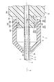
- FIG. 3 is a schematic cross-sectional view showing an internal configuration of the housing in the treatment instrument according to the first embodiment.
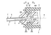
- FIG. 4 is a schematic cross-sectional view showing a state in which the central axis of the shaft matches the predetermined rotation axis of the housing in the treatment instrument according to the first embodiment.
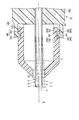
- FIG. 5 shows that in the treatment instrument according to the first embodiment, the rotation element receives an external force from the direction deviating from the central axis (predetermined rotational axis), and the central axis of the shaft is deviated from the predetermined rotational axis of the housing.
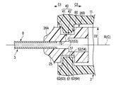
- FIG. 6 is a schematic cross-sectional view showing a state in which the radius D2 of the connecting portion of the rotating member is larger than the radius D1 shown in FIG. 4 in the treatment tool according to the first modification of the first embodiment.
- FIG. 7 shows a treatment instrument according to a first modification of the first embodiment, in which the rotational element shown in FIG. 6 receives an external force from the direction away from the central axis, and the center of the shaft with respect to a predetermined rotational axis of the housing. It is a rough sectional view showing the state where the axis shifted.
- FIG. 8 is a schematic cross-sectional view showing a state in which protrusions for effectively generating a frictional force against the housing are arranged on the rotating member in the treatment tool according to the second modification of the first embodiment.
- FIG. 9 is a schematic cross-sectional view showing a state in which a protrusion for effectively generating a frictional force against the rotating member is arranged on the housing in the treatment instrument according to the third modification of the first embodiment.
- FIG. 10 is a schematic cross-sectional view showing a state in which a friction plate for effectively generating a friction force against the housing is arranged on the rotating member in the treatment instrument according to the fourth modification of the first embodiment. .
- FIG. 11 is a schematic cross-sectional view showing a state in which a friction plate for effectively generating a frictional force against the rotating member is disposed in the housing in the treatment instrument according to the fifth modification of the first embodiment.
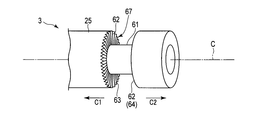
- FIG. 12 is a schematic perspective view showing a state in which a number of jagged steps for effectively generating a frictional force against the housing are formed on the rotating member in the treatment instrument according to the sixth modification of the first embodiment.
- FIG. FIG. 13A shows a treatment instrument according to a seventh modification of the first embodiment, in which a protrusion for effectively generating a frictional force against the housing is disposed on the rotating member, and the frictional force against the rotating member is effectively generated.
- FIG. 6 is a schematic cross-sectional view showing a state in which a recess that fits into the protrusion of the rotating member is disposed in the housing.
- FIG. 13B is a schematic cross-sectional view seen from the direction along line 13B-13B in FIG. 13A.
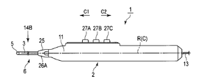
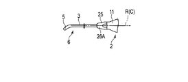
- FIG. 14A is a schematic diagram illustrating a treatment tool according to the second embodiment.
- FIG. 14B is a schematic diagram showing the rotating element and the rotating member as seen from the direction indicated by the arrow 14B in FIG. 14A.
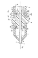
- FIG. 15 is a schematic diagram illustrating a state where drawing of the end effector is omitted in the treatment tool according to the third embodiment.
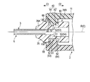
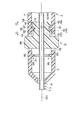
- FIG. 16 is a schematic cross-sectional view showing a state in which the central axis of the shaft matches the predetermined rotation axis of the housing in the treatment instrument according to the third embodiment.
- FIG. 17 shows a state in which the central axis of the shaft is coincident with a predetermined rotation axis of the housing in the treatment tool according to the third embodiment by a solid line, and the rotation element receives an external force from a direction away from the central axis.
- FIG. 3 is a schematic cross-sectional view showing a state in which the central axis of the shaft is displaced with respect to a predetermined rotation axis of the housing by a broken line.
- FIG. 18 shows, in a treatment instrument according to the first modification of the third embodiment, a state in which the central axis of the shaft coincides with a predetermined rotational axis of the housing by a solid line, and the direction in which the rotational element deviates from the central axis.
- FIG. 6 is a schematic cross-sectional view showing a state in which the center axis of the shaft is displaced with respect to a predetermined rotation axis of the housing and the outer peripheral surface of the shaft is in contact with the friction ring at the front end of the housing by receiving external force from the broken line.
- FIG. 19 is a schematic cross-sectional view showing a state in which the central axis of the shaft matches the predetermined rotation axis of the housing in the treatment instrument according to the second modification of the third embodiment.
- FIG. 20 shows a state in which the central axis of the shaft coincides with a predetermined rotation axis of the housing in the treatment instrument according to the second modification of the third embodiment by a solid line, and the direction in which the rotation element deviates from the central axis.
- FIG. 6 is a schematic cross-sectional view showing a state in which the central axis of the shaft is displaced with respect to a predetermined rotation axis of the housing by receiving an external force from a broken line.
- FIG. 21 is a schematic cross-sectional view showing a state where the central axis of the shaft matches the predetermined rotation axis of the housing in the treatment instrument according to the fourth embodiment.
- FIG. 22 shows, in a treatment instrument according to the fourth embodiment, a state in which the central axis of the shaft coincides with a predetermined rotational axis of the housing by a solid line, and receives an external force from a direction in which the rotational element deviates from the central axis.
- FIG. 3 is a schematic cross-sectional view showing a state in which the central axis of the shaft is displaced with respect to a predetermined rotation axis of the housing by a broken line.
- FIG. 1 is a view showing a treatment tool (gripping treatment tool) 1 of the present embodiment.
- the treatment instrument 1 shown in FIG. 1 has a predetermined rotation axis (longitudinal axis) R.
- a distal end side (arrow C1 side)
- a side opposite to the distal end side is defined as a proximal end side (arrow C2 side).
- the treatment instrument 1 includes a housing 2, a shaft (sheath) 3 protruding from the housing 2, and an end effector 5.
- the shaft 3 and the end effector 5 form a rotary element 6 with respect to a predetermined rotation axis R of the housing 2. That is, the rotating element 6 includes the shaft 3 and the end effector 5.
- the central axis C is defined for the shaft 3.
- the shaft 3 extends along the central axis C from the proximal end side to the distal end side.
- the end effector 5 is disposed at the tip of the shaft 3.
- the shaft 3 is supported rotatably with respect to the housing 2. Therefore, the shaft 3 supports the end effector 5 together with the shaft 3 so as to be rotatable about the central axis C.
- a side toward the housing 2 is a proximal end side
- a side toward the end effector 5 is a distal end side.
- the end effector 5 may be disposed on the central axis C, or may be disposed at a position shifted from the central axis C.
- the end effector 5 is movable between a position where the end effector 5 is disposed on the axis of the central axis C of the shaft 3 and a position where it is displaced from the position of the central axis C. It is. For this reason, in this embodiment, the end effector 5 is bent with respect to the shaft 3.
- the shaft 3 is formed of a metal material such as stainless steel, and can be elastically deformed by the load of the external force F applied to the rotary element 6 from the direction away from the central axis C (predetermined rotation axis R). Is preferred. For this reason, it is preferable that the shaft 3 has a tendency to bend moderately by the load of the external force F applied to the rotating element 6 from the direction deviating from the central axis C (predetermined rotation axis R).
- the housing 2 is formed of a resin material having electrical insulation.
- the housing 2 according to this embodiment includes a housing main body 11 extending along a predetermined (non-moving) rotation axis R, and a direction intersecting the predetermined rotation axis R from the housing main body 11 (arrows Y1 and Y2). And a grip (fixed handle) 12 extending along the direction indicated by.
- the grip 12 is provided at a site away from the predetermined rotation axis R.
- One end of a cable 13 is connected to the grip 12.
- the other end of the cable 13 is connected to an energy control device (not shown).
- FIG. 1 is a view of the treatment instrument 1 as viewed from one side in the width direction of the housing 2.
- FIG. 2 is a diagram showing a configuration of the end effector 5.
- the end effector 5 is rotatable with respect to the housing 2 around the rotation axis R (center axis C) together with the shaft 3, and the shaft 3 (center axis C). Can be bent.
- the end effector 5 can be rotated with respect to the housing 2 around the rotation axis R (center axis C) together with the shaft 3 and bendable with respect to the shaft 3 (center axis C). Is also suitable (see FIG. 14B).
- the shaft 3 rotates about the central axis C, the angular position of the end effector 5 about the rotational axis R changes.
- the end effector 5 includes a relay member 15, a first grip piece 16, and a second grip piece 17.
- the relay member 15 is attached to the tip of the shaft 3 so as to be bent with respect to the shaft 3. That is, a bending joint 18 is formed between the shaft 3 and the relay member 15.
- the end effector 5 can be opened and closed between a pair of gripping pieces 16 and 17.
- the opening / closing directions of the gripping pieces 16 and 17 intersect the central axis C and intersect the end effector 5 bending direction.
- the first gripping piece 16 is rotatably attached to the relay member 15 via a support pin (support portion) 19. That is, the relay member 15 is provided with a support pin 19 that supports the first gripping piece 16.
- the first gripping piece 16 can be rotated around the support pin 19.
- the rotation axis T ⁇ b> 1 of the first gripping piece 16 with respect to the relay member 15 passes through the support pin 19 and is substantially coaxial with the central axis of the support pin 19.
- the rotation axis T ⁇ b> 1 extends substantially parallel to the bending direction of the end effector 5.
- the extending direction of the rotation axis T1 intersects the central axis C of the shaft 3 and intersects the opening / closing direction of the gripping pieces 16 and 17.
- the support pin (support portion) 19 can rotate around the predetermined rotation axis R with respect to the housing 2 together with the shaft 3 and the end effector 5.
- the second gripping piece 17 is integrated with the relay member 15 or fixed to the relay member 15. In another embodiment, the second gripping piece 17 is also rotatably attached to the relay member 15. Furthermore, in another embodiment, a rod member (not shown) extends from the inside of the relay member 15 toward the distal end side, and the second gripping piece is formed by the protruding portion of the rod member from the relay member 15 toward the distal end side. 17 is formed.
- a handle (movable handle) 21 is rotatably attached to the housing 2.
- the handle 21 is opened or closed with respect to the grip 12 by rotating the handle 21 which is an opening / closing operation input unit with respect to the housing 2. That is, the handle 21 can be opened and closed with respect to the grip 12.
- the handle 21 since the treatment tool 1 is a pistol type, the handle 21 is located on the side where the grip 12 is located with respect to the rotation axis R and on the tip side with respect to the grip 12.
- the movement direction of the handle 21 in the opening operation and the closing operation with respect to the grip 12 is substantially parallel to the rotation axis R.
- the handle 21 may be provided on the proximal side with respect to the grip 12.
- the handle 21 and the grip 12 are provided on the opposite sides with respect to the rotation axis R, and the moving direction in the opening operation and the closing operation of the handle 21 with respect to the grip 12 is determined by the rotation axis R. May be substantially perpendicular to.
- the housing 2 is provided with a bending dial 23 as a bending operation input portion (operation input portion).
- a bending operation input portion operation input portion
- an operation for bending the end effector 5 with respect to the shaft 3 is input by rotating the bending dial 23.
- bending drive members 28 ⁇ / b> A and 28 ⁇ / b> B such as wires or leaf springs are extended along the rotation axis R inside the shaft 3.
- the distal ends (one end) of the bending drive members 28 ⁇ / b> A and 28 ⁇ / b> B are connected to the relay member 15 of the end effector 5.
- the base ends of the bending drive members 28A and 28B are mechanically connected to the bending dial 23 via a pulley (not shown) provided inside the housing 2.
- the bending drive members 28A and 28B can rotate with respect to the housing 2 around the predetermined rotation axis R (center axis C) together with the shaft 3 and the end effector 5.
- the bending dial 23 may be rotatable around a predetermined rotation axis R (center axis C) with respect to the housing 2 together with the shaft 3 and the end effector 5. It is not necessary to rotate around the predetermined rotation axis R (center axis C) together.
- the bending dial 23 is attached to the base end surface of the housing main body 11, but the position of the bending dial 23 is not limited to this.
- a bending operation input section such as a bending dial 23 may be attached to the outer surface of the housing main body 11 facing the side opposite to the side where the grip 12 is positioned with respect to the predetermined rotation axis R.
- Rotating member 25 that is a part of shaft 3 is supported on the front end side of housing body 11.
- the rotating member 25 is preferably formed of a resin material having electrical insulation.
- the rotating member 25 includes a rotating knob 26 ⁇ / b> A that is operated and a connecting portion 26 ⁇ / b> B that is connected to the housing 2.
- the rotary knob 26A and the connecting portion 26B are formed in an appropriate cylindrical shape. In order to generate a large rotational moment with a small force, the maximum radius (distance from the central axis C) D0 of the rotary knob 26A is appropriately increased.
- the maximum radius (distance from the central axis C) D0 of the rotary knob 26A is preferably formed larger than the maximum radius (distance from the central axis C) D1 of the connecting portion 26B.
- the shaft 3 is supported by the housing 2 while being inserted into the housing main body 11 from the distal end side.
- the rotating member 25 is fixed to the shaft 3 and rotates around the rotation axis R with respect to the housing 2 together with the shaft 3 and the end effector 5.
- an operation force that rotates the shaft 3 and the end effector 5, that is, the rotation element 6 around the axis of the predetermined rotation axis R (center axis C) is applied to the rotation member 25 that is a rotation operation input unit.
- Operation buttons 27A and 27B are attached to the housing 2. Each of the operation buttons 27A and 27B is pressed to input an operation.
- the treatment instrument 1 is operated in a predetermined operation mode. At this time, for example, as in a known treatment instrument, any of high-frequency current, ultrasonic vibration, and heater heat is applied as treatment energy to a treatment object grasped between the grasping pieces 16 and 17.
- the electric motor is driven, so that the gripping pieces 16 and 17 are moved. Staples may be punctured into the treatment target to be grasped.
- FIG. 3 is a diagram showing an internal configuration of the housing 2.
- FIG. 3 shows a cross section that is substantially perpendicular to (intersects with) the width direction of the housing 2.
- the bending drive members 28A and 28B and the configuration for transmitting the operating force from the bending dial 23 to the bending drive members 28A and 28B are omitted.
- a cylindrical movable member 31 is attached to the rotating member 25 from the base end side (arrow C ⁇ b> 2 side) inside the housing 2 (housing main body 11).
- the movable member 31 extends along a predetermined rotation axis R (center axis C) and is movable along the predetermined rotation axis R with respect to the housing 2 and the shaft 3.
- the first gripping piece 16 By opening the handle 21 with respect to the grip 12, the first gripping piece 16 opens relative to the second gripping piece 17, and by closing the handle 21 with respect to the grip 12, the first gripping piece Various mechanisms can be employed as the mechanism in which 16 closes relative to the second gripping piece 17.
- a slider member 32 is disposed on the outer peripheral surface of the movable member 31.
- the handle 21 is connected to the movable member 31 via the slider member 32.
- the movable member 31 is rotatable with respect to the handle 21 around a predetermined rotation axis R.
- a drive rod 33 that is an opening / closing drive member is fixed to the movable member 31 via a connection pin 35.
- the drive rod 33 extends along the rotation axis R from the inside of the movable member 31 through the inside of the shaft 3.
- the drive rod 33 Since the drive rod 33 is fixed to the movable member 31, the drive rod 33 is attached to the housing 2 together with the shaft 3, the end effector 5, and the movable member 31 when an operating force is applied on the rotating member 25. And rotate around a predetermined rotation axis R (center axis C).
- An urging member 37 such as a spring is provided inside the housing 2.
- the urging member 37 has one end connected to the housing 2 and the other end connected to the handle 21.
- the urging member 37 urges the handle 21 to open to the grip 12.
- the movable member 31 and the drive rod 33 When an operating force is applied to the handle 21 and the handle 21 is opened or closed with respect to the grip 12, the movable member 31 and the drive rod 33 have a predetermined rotation axis R (center axis C) with respect to the shaft 3 and the housing 2. Move along. As shown in FIG. 2, the drive rod (drive member) 33 extending through the inside of the shaft 3 has one end (tip) connected to the first gripping piece 16 of the end effector 5. In the present embodiment, the drive rod 33 is connected to the first gripping piece 16 via the connecting pin 36. When the movable member 31 and the drive rod (drive member) 33 move along the predetermined rotation axis R, at least the first gripping piece 16 rotates about the support pin 19 with respect to the relay member 15.
- the support pin 19 serves as a pivot point for the rotation of the first gripping piece 16
- the connecting pin 36 serves as a force point for applying a driving force from the drive rod 33 to the first gripping piece 16.
- the distal end of the drive rod (opening / closing drive member) 33 is added to the first gripping piece 16 and the second gripping piece 17. Also connected to. In this case, when the drive rod 33 moves along the rotation axis R, both the gripping pieces 16 and 17 rotate with respect to the relay member 15 and the gap between the gripping pieces 16 and 17 opens or closes.
- the biasing member 37 biases the first gripping piece 16 to the second gripping piece 17 and opens the end effector 5 so that the gap between the gripping pieces 16 and 17 is open. Be forced.
- the housing main body 11 of the housing 2 is provided with an engaging protrusion (supporting portion) 41 that protrudes toward a predetermined rotation axis R.
- the engaging protrusion 41 is disposed on the inner peripheral surface of the housing 2.
- the engagement protrusion (inner flange) 41 is provided over the entire circumference around a predetermined rotation axis R.
- the engagement protrusions 41 may be formed in the circumferential direction around the predetermined rotation axis R, for example, at appropriate intervals. For this reason, the engagement protrusion 41 may be one or plural.
- An engaging recess (supported portion) 42 that is recessed toward the inner peripheral side is provided in the connecting portion 26B of the rotating member 25 that is a part of the shaft 3.
- the engaging recess 42 is provided over the entire circumference around the rotation axis R.
- the engagement recess 42 can move around the rotation axis R with respect to the engagement protrusion 41.
- the rotating member 25 of the shaft 3 is rotatable about a predetermined rotation axis R with respect to the housing 2. Therefore, the engagement protrusion 41 and the engagement recess 42 form a joint (connection portion) 40 that connects the shaft 3 so as to be rotatable around a predetermined rotation axis R of the housing 2.
- FIG. 4 and 5 are diagrams showing the configuration of the joint 40 (engagement protrusion 41 and engagement recess 42) between the shaft 3 and the housing 2.
- FIG. 4 shows a state in which the central axis C of the shaft 3 coincides with the predetermined rotation axis R of the housing 2.
- FIG. 5 shows a state in which the central axis C of the shaft 3 is shifted with respect to a predetermined rotational axis R of the housing 2 by an external force F on the rotating element 6, that is, the end effector 5 and / or the shaft 3.
- the engagement protrusion 41 of the housing 2 has a support portion (rotation support surface) 51 and an engagement portion (sliding resistance generation portion) 52.
- the support portion 51 defines a cylindrical inner peripheral surface with respect to a predetermined rotation axis R.
- the support portion 51 supports the rotating element 6 so as to be rotatable around a predetermined rotation axis R.
- the engaging portion 52 is adjacent to the support portion 51 along the central axis C.
- the engaging portion 52 has a protrusion facing surface (first receiving surface) 53 facing the distal end side and a protrusion facing surface (second receiving surface) 54 facing the proximal end side.
- the engaging recess 42 of a part of the rotating member 25 of the shaft 3 has a supported portion (rotating support surface) 61 and an engaged portion (sliding resistance generating portion) 62. That is, the rotating element 6 includes a supported portion 61 that is provided on the shaft 3 and supported by the support portion 51 of the housing 2.
- the supported portion 61 defines a cylindrical outer peripheral surface with respect to the central axis C.
- the engaged portion 62 is adjacent to the supported surface 61 along the central axis C.
- the engaged portion 62 has a concave facing surface (first contact surface) 63 facing the proximal end side and a concave facing surface (second contact surface) 64 facing the distal end side.
- the support portion 51 and the supported portion 61 are formed of a material that suppresses the generation of frictional force when contacted, or is subjected to surface processing that suppresses the generation of frictional force.
- the support part 51 and the supported part 61 are preferably made of a material having a small coefficient of friction, such as POM, and good slipperiness (lubricity). For this reason, the supported portion 61 can rotate smoothly with respect to the support portion 51.
- the support part 51 of the housing 2 and the supported part 61 of the shaft 3 cooperate to form the rotation support mechanism 70.
- the concave facing surface (first contact surface) 63 facing the proximal end side of the engaging recess 42 faces the projection facing surface (first receiving surface) 53 facing the distal end side of the engaging projection 41.
- a concave facing surface (second contact surface) 64 facing the distal end side of the engaging recess 42 faces a projection facing surface (second receiving surface) 54 facing the proximal end side of the engaging projection 41.
- the frictional force (sliding resistance) between the supporting part 51 and the supported part 61 is formed so as to generate a large frictional force.
- the surface processing between the protrusion facing surface 53 of the engaging protrusion 41 and the concave facing surface 63 of the engaging recess 42 is made of a material that generates a large frictional force when contacted, or a surface treatment that easily generates a frictional force. It is preferable that it is done.
- the protrusion facing surface 54 of the engaging protrusion 41 and the concave facing surface 64 of the engaging recess 42 it is formed of a material that generates a large frictional force when contacted, or it is easy to generate a frictional force. It is preferable that the surface is processed.
- the engaging portion 52 of the housing 2 and the engaged portion 62 of the shaft 3 cooperate to form the lock mechanism 80.
- the lock mechanism 80 is disposed on the support portion 51 of the housing 2 and the supported portion 61 of the shaft 3.
- the lock mechanism 80 rotates as one of the rotation elements 6 positioned closer to the end effector 5 than the support position supported by the support portion 51 deviates from the axis of the predetermined rotation axis R.
- the element 6 is prevented from rotating around the predetermined rotation axis R.
- the rotation element 6 is prevented from rotating around the axis of the predetermined rotation axis R at a position (a different position) adjacent to the support portion 51 (the protrusion facing surface 53 of the engagement portion 52).
- the engagement portion (friction resistance portion) 52 cooperates with the engaged portion 62 and is in a direction around the axis of the predetermined rotation axis R at a position farther from the predetermined rotation axis R than the support portion 51. Generates sliding resistance.
- the engaging portion 52 of the housing 2 is in a position adjacent to the distal end side and the proximal end side of the support portion 51 along a predetermined rotation axis R. For this reason, the position of the support part 51 of the housing 2 and the position of the engaging part 52 are different.
- the engaged portion 62 of the shaft 3 is located along the central axis C adjacent to the distal end side and the proximal end side of the supported portion 61. For this reason, the position of the supported portion 61 of the shaft 3 and the position of the engaged portion 62 are different.
- the support portion 51 of the engagement protrusion 41 of the housing 2 and the supported portion 61 of the engagement recess 42 of the shaft 3 cooperate to change the center axis C of the shaft 3 to the housing of the housing 2. It is made to correspond to the predetermined rotation axis R of the main body 11.
- the inner diameter of the support portion 51 with respect to the rotation axis R is formed larger than the outer diameter of the supported portion 61 with respect to the central axis C.
- the support portion 51 of the engagement protrusion 41 of the housing 2 has a rattling, that is, play with respect to the supported portion 61 of the engagement recess 42 of the shaft 3.
- the outer peripheral surface of the supported portion 61 of the rotating member 25 and the inner peripheral surface of the support portion 51 of the housing 2 can partially contact each other.
- the supported portion 61 of the rotating member 25 is positioned at the position of the supporting portion 51 of the housing 2 that is currently in contact.
- the center axis C being parallel to the predetermined rotation axis R
- it moves to the opposite side across the predetermined rotation axis R (escapes)
- the center axis C of the shaft 3 is moved to the predetermined rotation axis of the housing 2. It can match or be close to R.
- the rotation member 25 when rotating the rotation member 25 around the axis of the predetermined rotation axis R (center axis C) with respect to the housing 2, the rotation member 25 can be rotated with the sliding resistance reduced (minimized state). Therefore, the joint 40 slides around the axis of the predetermined rotation axis R between the housing 2 and the shaft 3 in a state where the predetermined rotation axis R of the housing 2 and the center axis C of the shaft 3 coincide with each other. Minimize resistance.
- the rotation element 6, that is, the end effector 5 and / or the shaft 3, is located closer to the tip of the end effector 5 than the rotation member 25, from the direction away from the rotation axis R of the housing 2.
- a load (external force) F can be applied.
- the first holding piece 16 is urged to open with respect to the second holding piece 17 by the urging member 37 disposed inside the housing 2. For this reason, for example, even when the end effector 5 is on the axis of the central axis C of the shaft 3, the first gripping piece 16 side with the first gripping piece 16 open with respect to the second gripping piece 17.
- an external force F is applied from the direction, a force is applied to rotate the end effector 5 around the central axis C.
- the end effector 5 and / or the shaft 3 may generate a rotational moment about the central axis C due to an external force F from a position deviating from the central axis C.
- the rotating member 25 which is a part of the shaft 3 tries to rotate around the central axis C.
- the support portion 51 of the engagement protrusion 41 of the housing 2 has a rattling, that is, play with respect to the supported portion 61 of the engagement recess 42 of the shaft 3.
- the rotating member 25 is also tilted with respect to the housing 2 due to play (play) with respect to the housing 2.
- the example shown in FIG. 5 is for explaining the present embodiment in an easy-to-understand manner.
- the maximum inclination angle (inclination) of the central axis C of the rotation member 25 (shaft 3) with respect to the predetermined rotation axis R of the housing 2 The amount can be set as appropriate.
- the concave facing surface 63 of the engaged portion 62 of the rotating member 25 is in contact with the protrusion facing surface 53 of the engaging portion 52 of the housing 2.
- the contact position (friction generation position) between the protrusion facing surface 53 of the engaging portion 52 and the concave facing surface 63 of the engaged portion 62 is a distance d1 ( ⁇ D1) in the radial direction with respect to the predetermined rotation axis R. ) Position.
- the concave facing surface 63 of the engaged portion 62 of the rotating member 25 gradually comes into strong contact with the protrusion facing surface 53 of the engaging portion 52 of the housing 2.
- the braking action due to the sliding resistance that suppresses the rotation of the shaft 3 (rotating member 25) about the predetermined rotation axis R relative to the housing 2 also increases. Therefore, unintended rotation of the rotating member 25 with respect to the housing 2 is suppressed.
- the rotation member 25 may be rotated around the predetermined rotation axis R against the sliding resistance (frictional force) generated between the rotation member 25 and the housing 2 by the external force F.
- the surgeon rotates the rotating member 25 around the central axis C, the moment between the rotating member 25 and the housing 2 is reduced with a smaller force due to the moment relationship based on the difference in the sizes of the radii D0 and D1.
- the rotating member 25 can be rotated against the sliding resistance (frictional force) generated in the above. For this reason, the surgeon can push away the living tissue, for example, with the end effector 5 by rotating the end effector 5 at a position shifted from the axis of the central axis C around the axis of the central axis C.
- a position closer to the end effector 5 than the support position supported by the support portion 51 among the rotation elements 6 by an external force F from a direction deviating from a predetermined rotation axis R for example, a position closer to the end effector 5 than the support position supported by the support portion 51 among the rotation elements 6 by an external force F from a direction deviating from a predetermined rotation axis R. Any of these can be shifted from the axis of the predetermined rotation axis R.
- the engaging portion (sliding resistance generating portion) 52 and the engaged portion (sliding resistance generating portion) 62 of the lock mechanism 80 of the joint 40 are shifted from the predetermined rotation axis R with respect to the center axis C.
- a sliding resistance about a predetermined rotation axis R is generated between the housing 2 and the rotation element 6.
- the joint 40 has a predetermined rotation axis R on the rotating element 6 (shaft 3) at a position closer to the end effector 5 than a supporting position where the shaft 5 of the rotating element 6 is supported by the support portion 51 of the housing 2.
- the sliding resistance around the axis is generated.
- the joint 40 is adjacent to a support position (supported part 61) that supports the shaft 3 of the rotating element 6 by the support part 51 of the housing 2, and has a predetermined rotation axis R from the support position.
- a sliding resistance is generated in the direction around the predetermined rotation axis R with respect to the engaging portion 52 by the engaged portion 62 away from the engaging portion 52. That is, a sliding resistance around the predetermined rotation axis R is generated in the rotating element 6 (shaft 3).
- the lock mechanism 80 can suppress the rotation element 6 from rotating around the predetermined rotation axis R. Therefore, for example, when an external force F is applied to the end effector 5 disposed at a position shifted from the central axis C, the lock mechanism 80 causes the end effector 5 and the shaft 3 to move along the predetermined rotation axis R that the operator does not intend. The rotation around the axis can be effectively prevented.
- the rotary knob 26A having a radius D0 larger than the radius D1 of the portion where the sliding resistance is generated. Can be rotated. For this reason, the surgeon can easily rotate the rotary knob 26A around the predetermined rotation axis R against the sliding resistance by the rotation moment.
- the protrusion facing surface 53 facing the distal end side of the engaging portion 52 of the housing 2 is The example which the concave opposing surface 63 which faces the base end side of the to-be-engaged part 62 of the rotating member 25 contacts was demonstrated.
- the concave facing surface 63 facing the base end side of the engaged portion 62 of the rotating member 25 contacts the projection facing surface 53 facing the distal end side of the engaging portion 52 of the housing 2, and at the same time, the engagement of the housing 2. It is also preferable that the concave facing surface 64 facing the distal end side of the engaged portion 62 of the rotating member 25 contacts the projection facing surface 54 facing the proximal end side of the joining portion 52.
- the maximum radius D2 of the connecting portion 26B shown in FIG. 6 is formed larger than the maximum radius D1 (see FIG. 4) of the connecting portion 26B described in the first embodiment.
- the central axis C of the shaft 3 of the rotating element 6 is inclined with respect to the predetermined rotating axis R of the housing 2.
- the contact position (friction generation position) between the concave facing surface 63 of the engaged portion 62 and the protrusion facing surface 53 of the engaging portion 52 is a position at a distance d2 ( ⁇ D2) with respect to the predetermined rotation axis R. It is in.
- the distance d2 is larger than the distance d1 (see FIG.
- a protrusion 65 is formed on the concave facing surface 63 of the engaged portion 62.
- the protrusion 65 protrudes more proximally than the concave facing surface 63 of the engaged portion 62.
- the protrusion 65 is preferably formed in an annular shape around the central axis C.
- the protrusion 65 is brought into contact with the protrusion facing surface 53 of the engaging portion 52, it is stronger than the concave facing surface 63 of the engaged portion 62 described in the first embodiment is protruded. Abutted. Therefore, in this modification, when the same external force F is loaded at the same position of the end effector 5 and / or the shaft 3, the predetermined rotation axis R is compared with the example described in the first embodiment (see FIG. 5). A large sliding resistance (frictional force) can be generated around the axis.
- a protrusion 55 is formed on the protrusion facing surface 53 of the engagement portion 52 of the engagement recess 42.
- the protruding portion 55 protrudes toward the concave facing surface 63 of the engaged portion 62.
- the protrusion 55 is preferably formed in an annular shape. For this reason, when the protrusion 55 is brought into contact with the concave facing surface 63 of the engaged portion 62 by the external force F applied to the rotating element 6, the protrusion facing surface 53 of the engaging portion 52 described in the first embodiment is formed. It abuts more strongly than it abuts as much as it protrudes.
- this modification can be appropriately combined with, for example, the first embodiment, the first modification, and the second modification.
- a friction plate 66 is fixed to the concave facing surface 63 of the engaged portion 62.
- the friction plate 66 is preferably formed in an annular shape.
- the friction plate 66 is preferably formed of a material having a large friction coefficient, such as a rubber material.
- the friction plate 66 protrudes more proximally than the concave facing surface 63 of the engaged portion 62 and increases the frictional force when the projection facing surface 53 of the engaging portion 52 comes into contact. For this reason, when the friction plate 66 is brought into contact with the protrusion facing surface 53 of the engaging portion 52, the frictional force is larger than that of the concave facing surface 63 of the engaged portion 62 described in the first embodiment. Demonstrate.
- This modification can be appropriately combined with, for example, the third modification.
- a friction plate 56 is fixed to the protrusion facing surface 53 of the engaging portion 52.
- the friction plate 56 is preferably formed in an annular shape.
- the friction plate 56 increases the frictional force when the concave facing surface 63 of the engaged portion 62 comes into contact. For this reason, when the friction plate 56 is brought into contact with the concave facing surface 63 of the engaged portion 62, the frictional force is larger than that of the protrusion facing surface 53 of the engaging portion 52 described in the first embodiment. Demonstrate. Therefore, in this modification, when the same external force F is loaded at the same position of the end effector 5 and / or the shaft 3, the predetermined rotation axis R is compared with the example described in the first embodiment (see FIG. 5). A large sliding resistance (frictional force) can be generated around the axis.
- This modification can be appropriately combined with the second modification, for example.
- the concave facing surface 63 of the engaged portion 62 is formed with a number of steps 67 along the circumferential direction of the central axis C. That is, the concave facing surface 63 of the engaged portion 62 is formed in a jagged shape. For this reason, when the concave facing surface 63 of the engaged portion 62 is brought into contact with the projection facing surface 53 of the engaging portion 52, the base surface C extends along the central axis C of the concave facing surface 63 of the engaged portion 62.
- the protrusion facing surface 53 of the engaging portion 52 is hooked at a position convex toward the end side.
- the step 67 may be formed on the concave facing surface 64 of the engaged portion 62.
- the step 67 may be formed on the protrusion facing surface 53 of the engaging portion (sliding resistance generating portion) 52 or may be formed on the protrusion facing surface 54 of the engaging portion 52.
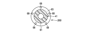
- one or more protrusions 68 are formed on the concave facing surface 63 of the engaged portion 62.
- the five protrusions 68 are arranged at the apex of a regular pentagon with respect to the central axis C.
- the protrusion 68 protrudes from the concave facing surface 63 of the engaged portion 62 toward the base end side along the central axis C.
- a recess 58 is formed in the protrusion facing surface 53 of the engaging portion 52.
- the number of the recesses 58 may be the same as that of the protrusions 68, or may be a large number or a small number.
- the protrusion 68 can be fitted to the recess 58 at one or a plurality of positions. Therefore, in this modification, when the same external force F is loaded at the same position of the end effector 5 and / or the shaft 3, the predetermined rotation axis R is compared with the example described in the first embodiment (see FIG. 5). A large sliding resistance (frictional force) can be generated around the axis.
- FIGS. 14A and 14B This embodiment is a modification of the first embodiment including each modification.
- the same members or members having the same functions as those described in the first embodiment are denoted by the same reference numerals as much as possible. Description is omitted.
- the example in which the end effector 5 is actively movable at the tip of the shaft 3 has been described. Further, an example in which the pair of gripping pieces 16 and 17 (see FIGS. 1 and 2) of the end effector 5 can be relatively opened and closed has been described.
- the end effector 5 is integrally formed at the tip of the shaft 3 and the end effector 5 is bent with respect to the shaft 3 will be described. That is, in the present embodiment, the end effector 5 is curved with respect to the shaft 3 and is at a position shifted from the central axis C.
- operation buttons 27A, 27B, and 27C are attached to the main body 11 of the housing 2. Each of the operation buttons 27A, 27B, and 27C is pressed to perform an operation input.
- the treatment instrument 1 is operated in a predetermined operation mode. At this time, for example, as in a known treatment instrument, any of high-frequency current, ultrasonic vibration, and heater heat is applied as treatment energy to a treatment target with which the end effector 5 is in contact.
- the rotary knob 26A of the rotary member 25 when the operator operates the rotary knob 26A of the rotary member 25, for example, the end effector 5 against the frictional force between the housing 2 and the rotary member 25 from the relationship of the rotary moment with respect to the predetermined rotary axis R, for example.
- the rotary knob 26A can be rotated so as to push away the living tissue.
- This embodiment is a modification of the first embodiment and the second embodiment including the first to seventh modifications, and has the same members or the same functions as the members described in the first and second embodiments.
- the members having the same reference numerals are assigned as much as possible, and detailed description thereof is omitted.
- the rotation member 25 includes a rotation knob 26A, a first connection part (base end side connection part) 26B, and a second connection part (tip end side connection part) 26C.
- the housing body 11 is formed with openings 11A and 11B for projecting the rotary knob 26A.
- the openings 11A and 11B are preferably formed on the side surface of the housing body 11 shown in FIG.
- a first engagement protrusion 141 is formed on the housing 2 on the base end side along a predetermined rotation axis R with respect to the openings 11A and 11B.
- a second engagement protrusion 241 is formed on the housing 2 along the predetermined rotation axis R with respect to the openings 11A and 11B.
- a first engaging recess 142 that engages with the first engaging protrusion 141 of the housing 2 is formed on the outer peripheral surface of the first connecting portion 26 ⁇ / b> B of the rotating member 25.
- the first engagement protrusion 141 and the first engagement recess 142 constitute the first joint 140.
- a second engagement recess 242 that engages with the second engagement protrusion 241 of the housing 2 is formed on the outer peripheral surface of the second coupling portion 26 ⁇ / b> C of the rotating member 25.
- the second engagement protrusion 241 and the second engagement recess 242 constitute a second joint 240.
- the maximum radii of the first connecting portion 26B and the second connecting portion 26C are the same at D1.
- the maximum radius D1 between the first connecting portion 26B and the second connecting portion 26C is smaller than the maximum radius D0 of the rotary knob 26A.
- An opening 2A through which the shaft 3 passes is formed at the tip of the housing body 11.
- the opening 2A has an inner diameter larger than the outer diameter of the shaft 3 so as to allow the shaft 3 to bend appropriately. For this reason, the shaft 3, that is, the rotating element 6 can be bent with respect to the central axis C by an external force F from a direction deviated from the predetermined rotation axis R.
- the engagement protrusion 141 of the housing 2 includes a support portion (rotation support surface) 151 and an engagement portion 152.
- the support portion 151 defines a cylindrical inner peripheral surface with respect to a predetermined rotation axis R.
- the engaging portion 152 is adjacent to the support portion 151 along a predetermined rotation axis R.
- the engaging portion 152 has a protrusion facing surface (first receiving surface) 153 facing the distal end side and a protrusion facing surface (second receiving surface) 154 facing the proximal end side.
- the engaging recess 142 of a part of the rotating member 25 of the shaft 3 includes a supported portion (rotating support surface) 161 and an engaged portion 162.
- the supported portion 161 defines a cylindrical outer peripheral surface with respect to the central axis C.
- the engaged portion 162 is adjacent to the supported surface 161 along the central axis C.
- the engaged portion 162 has a concave facing surface (first contact surface) 163 facing the proximal end side and a concave facing surface (second contact surface) 164 facing the distal end side.
- the support portion 151 of the housing 2 and the supported portion 161 of the shaft 3 cooperate to form the rotation support mechanism 170.
- the engaging portion 152 of the housing 2 and the engaged portion 162 of the shaft 3 cooperate to form the lock mechanism 180.
- sliding resistance can be generated by the inclination of the central axis C of the shaft 3 of the rotating element 6 with respect to the predetermined rotating axis R.
- the engagement protrusion 241 of the housing 2 has a support portion (rotation support surface) 251 and an engagement portion 252.
- the support portion 251 defines a cylindrical inner peripheral surface with respect to a predetermined rotation axis R.
- the engaging portion 252 is adjacent to the support portion 251 along the central axis C.
- the engaging portion 252 has a protrusion facing surface (first receiving surface) 253 facing the distal end side and a protrusion facing surface (second receiving surface) 254 facing the proximal end side.
- the engaging recess 242 of a part of the rotating member 25 of the shaft 3 has a supported portion (rotating support surface) 261 and an engaged portion 262.
- the supported portion 261 defines a cylindrical outer peripheral surface with respect to the central axis C.
- the engaged portion 262 is adjacent to the supported surface 261 along the central axis C.
- the engaged portion 262 has a concave facing surface (first contact surface) 263 facing the proximal end side and a concave facing surface (second contact surface) 264 facing the distal end side.
- sliding resistance can be generated by the inclination of the central axis C of the shaft 3 of the rotating element 6 with respect to the predetermined rotating axis R.
- the support portion 251 of the housing 2 and the supported portion 261 of the shaft 3 cooperate to form the rotation support mechanism 270.
- the engaging portion 252 of the housing 2 and the engaged portion 262 of the shaft 3 cooperate to form a lock mechanism 280.
- the support portion 151 of the engagement protrusion 141 of the housing 2 and the supported portion 161 of the engagement recess 142 of the shaft 3 cooperate to change the central axis C of the shaft 3 to the housing of the housing 2. It is made to correspond to the predetermined rotation axis R of the main body 11.
- the support portion 251 of the engagement protrusion 241 of the housing 2 and the supported portion 261 of the engagement recess 242 of the shaft 3 cooperate with each other so that the central axis C of the shaft 3 is It is made to correspond with the predetermined
- the first joint 140 is formed with less backlash than the second joint 240.
- the treatment instrument 1 of the present embodiment supports the shaft 3 with respect to the housing 2 at two locations (joints 140 and 240) along a predetermined rotation axis R. For this reason, compared with the example (refer FIG. 5) which supported the shaft 3 at one place (joint 40) with respect to the housing 2 demonstrated in 1st Embodiment, it can be made difficult to incline the shaft 3.
- the shaft 3 can shift the rotation element 6 with respect to the predetermined rotation axis R of the housing 2 by elastic deformation due to the load of the external force F applied to the rotation element 6 from the direction away from the predetermined rotation axis R. It has possible flexibility. For this reason, the center axis C of the shaft 3 is shifted with respect to the predetermined rotation axis R by the bending of the shaft 3 with respect to the housing 2.
- the rotation of the shaft 3 around the central axis C of the shaft 3 is suppressed as the rotation of the rotating member 25 with respect to the housing 2 is suppressed, and further, the rotation around the central axis C is further suppressed.
- the rotation of the end effector 5 is suppressed. For example, when an external force F is applied to the end effector 5 disposed at a position shifted from the center axis C, the lock mechanism 280 rotates the end effector 5 and the shaft 3 about a predetermined rotation axis R that the operator does not intend. Can be effectively prevented.
- the rotary knob 26A having a radius D0 larger than the radius D1 of the portion where the sliding resistance is generated. Can be rotated. For this reason, the surgeon can easily rotate the rotary knob 26A around the predetermined rotation axis R against the sliding resistance by the rotation moment. For this reason, for example, the surgeon can push away the living tissue, for example, by rotating the end effector 5 at a position displaced from the central axis C around the central axis C. It should be noted that when the surgeon rotates the rotating member 25 against frictional force (sliding resistance), the shaft 3 is avoided so as to avoid friction between the engaging portion 252 and the engaged portion 262.
- the central axis C of the housing 2 tries to move so as to coincide with a predetermined rotation axis R of the housing 2.
- the lock mechanism 180 when an external force F is applied to the end effector 5 disposed at a position shifted from the central axis C, the lock mechanism 180 also cooperates with the lock mechanism 280 in accordance with the magnitude of the external force F.
- the end effector 5 and the shaft 3 can exhibit the function of preventing the rotation around the predetermined rotation axis R which is not intended by the operator.
- a friction ring 2 ⁇ / b> B is formed on the inner peripheral surface of the opening 2 ⁇ / b> A at the tip of the main body 11 of the housing 2.
- a joint 340 is formed by deforming the structure of the second joint 240.
- An engaging protrusion 341 is formed on the inner peripheral surface of the main body 11 of the housing 2 so as to face the outer peripheral surface of the flange 3A.
- An engagement portion 352 that generates a frictional force is formed on the inner peripheral surface of the engagement protrusion 341 with respect to the predetermined rotation axis R.
- a flange 3A is formed on the outer peripheral surface of the shaft 3 so as to protrude radially outward with respect to the central axis C.
- the outer diameter of the flange 3 ⁇ / b> A is smaller than the inner diameter of the engaging portion 352 of the engaging protrusion 341 of the housing 2.
- the outer peripheral surface of the flange 3A is processed or coated so as to generate appropriate friction with an engaging portion 352 described later.
- the engaging portion 352 of the housing 2 and the engaged portion 362 on the outer peripheral surface of the flange 3 ⁇ / b> A of the shaft 3 cooperate to form the lock mechanism 380.
- the lock mechanism 380 causes the end effector 5 and the shaft 3 to rotate around the predetermined rotation axis R. It can be effectively prevented.
- the lock mechanism 180 when an external force F is applied to the end effector 5 disposed at a position shifted from the central axis C, the lock mechanism 180 also cooperates with the lock mechanism 380 in accordance with the magnitude of the external force F.
- the function of preventing the end effector 5 and the shaft 3 from rotating around a predetermined rotation axis R that is not intended by the operator can be exhibited.
- the rotating member 25 includes a rotating knob 26A, a first connecting portion (base end side connecting portion) 26D, and a second connecting portion (tip end side connecting portion) 26E.
- the treatment instrument 1 includes a first joint 440 and a second joint 540.
- the first joint 440 has an engagement protrusion (support portion) 441 and an engagement recess (supported portion) 442.
- the first connecting portion 26D of the rotating member 25 is provided with an engaging protrusion (supporting portion) 441 that protrudes toward the inner peripheral side.
- the engagement protrusion (inner flange) 441 is provided over the entire circumference about the central axis C of the shaft 3.
- the engaging protrusions 441 may be formed in the circumferential direction around the central axis C of the shaft 3, for example, at appropriate intervals. For this reason, the engagement protrusion 441 may be one or plural.
- An engaging recess (supported portion) 442 that is recessed toward the inner periphery is provided on the outer peripheral surface of the main body 11 of the housing 2.
- the engaging recess 442 is provided over the entire circumference around the rotation axis R.
- the engagement protrusion 441 can move around the predetermined rotation axis R with respect to the engagement recess 442.
- the rotating member 25 of the shaft 3 is rotatable about a predetermined rotation axis R with respect to the housing 2. Therefore, the engagement protrusion 441 and the engagement recess 442 form a joint (connection portion) 440 that connects the shaft 3 so as to be rotatable around the predetermined rotation axis R of the housing 2.
- the engaging protrusion 441 of the rotating member 25 includes a support portion (rotating support surface) 451 and an engaging portion (sliding resistance generating portion) 452.
- the support portion 451 defines a cylindrical inner peripheral surface with respect to the central axis C of the shaft 3.
- the engaging portion 452 is adjacent to the support portion 451 along the central axis C.
- the engaging portion 452 has a protrusion facing surface (first receiving surface) 453 facing the distal end side and a protrusion facing surface (second receiving surface) 454 facing the proximal end side.
- the engaging recess 442 on the outer peripheral surface of the housing 2 has a supported portion (rotating support surface) 461 and an engaged portion (sliding resistance generating portion) 462.
- the supported portion 461 defines a cylindrical outer peripheral surface with respect to a predetermined rotation axis R.
- the engaged portion 462 is adjacent to the supported surface 461 along the rotation axis R.
- the engaged portion 462 has a concave facing surface (first contact surface) 463 facing the proximal end side and a concave facing surface (second contact surface) 464 facing the distal end side.
- the concave facing surface (first contact surface) 463 facing the base end side of the engaging recess 442 faces the projection facing surface (first receiving surface) 453 facing the distal end side of the engaging projection 441.
- a concave facing surface (second contact surface) 464 facing the distal end side of the engaging recess 442 faces a projection facing surface (second receiving surface) 454 facing the proximal end side of the engaging projection 41.
- the support portion 451 of the housing 2 and the supported portion 461 of the shaft 3 cooperate to form the rotation support mechanism 470.
- the engaging portion 452 of the housing 2 and the engaged portion 462 of the shaft 3 cooperate to form a lock mechanism 480.
- the second joint 540 has an engaging protrusion (supporting portion) 541 and an engaging recess (supported portion) 542.
- the second connecting portion 26E of the rotating member 25 is provided with an engaging protrusion (supporting portion) 541 that protrudes toward the inner peripheral side.
- the engagement protrusion (inner flange) 541 is provided over the entire circumference around the central axis C of the shaft 3.
- the engaging protrusions 541 may be formed in the circumferential direction around the central axis C of the shaft 3, for example, at appropriate intervals. For this reason, the engagement protrusion 541 may be one or plural.
- An engagement recess (supported portion) 542 that is recessed toward the inner periphery is provided on the outer peripheral surface of the main body 11 of the housing 2.
- the engaging recess 542 is provided over the entire circumference around the rotation axis R.
- the engagement protrusion 541 can move around the predetermined rotation axis R with respect to the engagement recess 542.
- the rotating member 25 of the shaft 3 is rotatable about a predetermined rotation axis R with respect to the housing 2. Therefore, the engagement protrusion 541 and the engagement recess 542 form a joint (connection portion) 540 that connects the shaft 3 so as to be rotatable around the predetermined rotation axis R of the housing 2.
- the engaging protrusion 541 of the rotating member 25 has a support portion (rotating support surface) 551 and an engaging portion (sliding resistance generating portion) 552.
- the support portion 551 defines a cylindrical inner peripheral surface with respect to the central axis C of the shaft 3.
- the engaging portion 552 is adjacent to the support portion 551 along the central axis C.
- the engaging portion 552 has a protrusion facing surface (first receiving surface) 553 facing the distal end side and a protrusion facing surface (second receiving surface) 554 facing the proximal end side.
- the engaging recess 542 on the outer peripheral surface of the housing 2 includes a supported portion (rotating support surface) 561 and an engaged portion (sliding resistance generating portion) 562.
- the supported portion 561 defines a cylindrical outer peripheral surface with respect to a predetermined rotation axis R.
- the engaged portion 562 is adjacent to the supported surface 561 along the rotation axis R.
- the engaged portion 562 has a concave facing surface (first contact surface) 563 that faces the proximal end side, and a concave facing surface (second contact surface) 564 that faces the distal end side.
- the concave facing surface (first contact surface) 563 facing the base end side of the engaging recess 542 faces the projection facing surface (first receiving surface) 553 facing the distal end side of the engaging projection 541.
- a concave facing surface (second contact surface) 564 facing the distal end side of the engaging recess 542 faces a projection facing surface (second receiving surface) 554 facing the proximal end side of the engaging projection 41.
- the engaging portion 552 is located adjacent to the distal end side and the proximal end side of the support portion 551. For this reason, the position of the support part 551 and the position of the engaging part 552 are different.
- the engaged portion 562 is located adjacent to the distal end side and the proximal end side of the supported portion 561. For this reason, the position of the supported portion 561 and the position of the engaged portion 562 are different.
- the support portion 551 of the housing 2 and the supported portion 561 of the shaft 3 cooperate to form a rotation support mechanism 570.
- the engaging portion 552 of the housing 2 and the engaged portion 562 of the shaft 3 cooperate to form a lock mechanism 580.
- the support portion 451 of the engagement protrusion 441 of the housing 2 and the supported portion 461 of the engagement recess 442 of the shaft 3 cooperate with each other so that the central axis C of the shaft 3 is changed to the housing of the housing 2. It is made to correspond to the predetermined rotation axis R of the main body 11.
- the support portion 551 of the engagement protrusion 541 of the housing 2 and the supported portion 561 of the engagement recess 542 of the shaft 3 cooperate with each other so that the center axis C of the shaft 3 is It is made to correspond with the predetermined
- the support portion 551 of the engagement protrusion 541 of the rotation member 25 cooperates with the supported portion 561 of the engagement recess 542 of the housing 2 to rotate the center axis C of the shaft 3 with the predetermined rotation of the housing body 11 of the housing 2.
- the inner diameter of the support portion 551 with respect to the central axis C is formed larger than the outer diameter of the supported portion 561 with respect to the predetermined rotation axis R.
- the support portion 551 of the engagement protrusion 541 of the rotating member 25 has a rattle, that is, play with respect to the supported portion 561 of the engagement recess 542 of the housing 2.
- the treatment instrument 1 of the present embodiment supports the shaft 3 with respect to the housing 2 at two locations (joints 440 and 540) along a predetermined rotation axis R.
- the shaft 3 can shift the rotation element 6 with respect to the predetermined rotation axis R of the housing 2 by elastic deformation due to the load of the external force F applied to the rotation element 6 from the direction away from the predetermined rotation axis R. It has possible flexibility. For this reason, the center axis C of the shaft 3 is shifted with respect to the predetermined rotation axis R by the bending of the shaft 3 with respect to the housing 2.
- the lock mechanism 580 can suppress the rotation element 6 from rotating around the predetermined rotation axis R. More specifically, the lock mechanism 580 can suppress the rotation element 6 from rotating about the predetermined rotation axis R at a position different from the support portion 551. Therefore, for example, when an external force F is applied to the end effector 5 disposed at a position shifted from the central axis C, the lock mechanism 580 causes the end effector 5 and the shaft 3 to move along the predetermined rotation axis R that is not intended by the operator. The rotation around the axis can be effectively prevented.
- the main body 11 of the housing 2 rotates with a radius D0 larger than the maximum radius D3 with respect to the predetermined rotation axis R.
- the knob 26A may be rotated. For this reason, the surgeon can easily rotate the rotary knob 26A around the predetermined rotation axis R against the sliding resistance by the rotation moment.
- the lock mechanism 480 cooperates with the lock mechanism 580 in accordance with the magnitude of the external force to end the end effector 5.
- the effector 5 and the shaft 3 can be effectively prevented from rotating around the predetermined rotation axis R that is not intended by the operator.
Landscapes
- Health & Medical Sciences (AREA)
- Surgery (AREA)
- Life Sciences & Earth Sciences (AREA)
- Engineering & Computer Science (AREA)
- Veterinary Medicine (AREA)
- Molecular Biology (AREA)
- Nuclear Medicine, Radiotherapy & Molecular Imaging (AREA)
- Public Health (AREA)
- Biomedical Technology (AREA)
- Heart & Thoracic Surgery (AREA)
- Medical Informatics (AREA)
- General Health & Medical Sciences (AREA)
- Animal Behavior & Ethology (AREA)
- Otolaryngology (AREA)
- Plasma & Fusion (AREA)
- Physics & Mathematics (AREA)
- Dentistry (AREA)
- Mechanical Engineering (AREA)
- Ophthalmology & Optometry (AREA)
- Surgical Instruments (AREA)
Abstract
L'instrument de traitement selon l'invention comporte: un élément rotatif; un boîtier comportant une partie support soutenant l'élément rotatif de façon à ce qu'il puisse pivoter autour d'un axe de rotation prédéterminé; et un mécanisme de verrouillage qui permet de limiter la rotation de l'élément rotatif autour de l'axe de rotation prédéterminé, lorsque, dans l'élément rotatif, une des positions se rapprochant davantage de l'effecteur de l'instrument que la position support adoptée par la partie support est décalée au-dessus de l'axe de rotation prédéterminé.
Priority Applications (4)
| Application Number | Priority Date | Filing Date | Title |
|---|---|---|---|
| CN201680086967.3A CN109328038B (zh) | 2016-06-20 | 2016-06-20 | 处置器具 |
| PCT/JP2016/068287 WO2017221305A1 (fr) | 2016-06-20 | 2016-06-20 | Instrument de traitement |
| JP2018523176A JP6623295B2 (ja) | 2016-06-20 | 2016-06-20 | 処置具 |
| US16/227,269 US11707316B2 (en) | 2016-06-20 | 2018-12-20 | Treatment instrument |
Applications Claiming Priority (1)
| Application Number | Priority Date | Filing Date | Title |
|---|---|---|---|
| PCT/JP2016/068287 WO2017221305A1 (fr) | 2016-06-20 | 2016-06-20 | Instrument de traitement |
Related Child Applications (1)
| Application Number | Title | Priority Date | Filing Date |
|---|---|---|---|
| US16/227,269 Continuation US11707316B2 (en) | 2016-06-20 | 2018-12-20 | Treatment instrument |
Publications (1)
| Publication Number | Publication Date |
|---|---|
| WO2017221305A1 true WO2017221305A1 (fr) | 2017-12-28 |
Family
ID=60784320
Family Applications (1)
| Application Number | Title | Priority Date | Filing Date |
|---|---|---|---|
| PCT/JP2016/068287 Ceased WO2017221305A1 (fr) | 2016-06-20 | 2016-06-20 | Instrument de traitement |
Country Status (4)
| Country | Link |
|---|---|
| US (1) | US11707316B2 (fr) |
| JP (1) | JP6623295B2 (fr) |
| CN (1) | CN109328038B (fr) |
| WO (1) | WO2017221305A1 (fr) |
Cited By (1)
| Publication number | Priority date | Publication date | Assignee | Title |
|---|---|---|---|---|
| JP2023509757A (ja) * | 2020-01-09 | 2023-03-09 | ボストン サイエンティフィック サイムド,インコーポレイテッド | 回転可能な医療デバイス |
Families Citing this family (1)
| Publication number | Priority date | Publication date | Assignee | Title |
|---|---|---|---|---|
| US11596467B2 (en) * | 2020-02-04 | 2023-03-07 | Covidien Lp | Articulating tip for bipolar pencil |
Citations (2)
| Publication number | Priority date | Publication date | Assignee | Title |
|---|---|---|---|---|
| JP2011092743A (ja) * | 2009-10-30 | 2011-05-12 | Tyco Healthcare Group Lp | ジョーロールジョイント |
| JP2013176651A (ja) * | 2006-06-13 | 2013-09-09 | Intuitive Surgical Operations Inc | 回転ロック部を有するツール |
Family Cites Families (10)
| Publication number | Priority date | Publication date | Assignee | Title |
|---|---|---|---|---|
| US5174300A (en) * | 1991-04-04 | 1992-12-29 | Symbiosis Corporation | Endoscopic surgical instruments having rotatable end effectors |
| US5383888A (en) | 1992-02-12 | 1995-01-24 | United States Surgical Corporation | Articulating endoscopic surgical apparatus |
| DE4323093A1 (de) * | 1993-07-10 | 1995-01-19 | Wolf Gmbh Richard | Chirurgische Zange |
| US5649955A (en) * | 1994-03-17 | 1997-07-22 | Terumo Kabushiki Kaisha | Surgical instrument |
| US7708758B2 (en) * | 2006-08-16 | 2010-05-04 | Cambridge Endoscopic Devices, Inc. | Surgical instrument |
| DE102006047204B4 (de) * | 2006-10-05 | 2015-04-23 | Erbe Elektromedizin Gmbh | Rohrschaftinstrument |
| US8679098B2 (en) * | 2011-09-13 | 2014-03-25 | Covidien Lp | Rotation knobs for surgical instruments |
| EP3092436B1 (fr) * | 2014-01-06 | 2017-11-01 | Philips Lighting Holding B.V. | Mecanisme d'arrêt pour dispositif rotatif |
| US10111698B2 (en) * | 2015-04-16 | 2018-10-30 | Ethicon Llc | Surgical instrument with rotatable shaft having plurality of locking positions |
| US10172609B2 (en) * | 2015-10-21 | 2019-01-08 | Ethicon Llc | Suturing instrument with locking articulation knob |
-
2016
- 2016-06-20 WO PCT/JP2016/068287 patent/WO2017221305A1/fr not_active Ceased
- 2016-06-20 CN CN201680086967.3A patent/CN109328038B/zh active Active
- 2016-06-20 JP JP2018523176A patent/JP6623295B2/ja active Active
-
2018
- 2018-12-20 US US16/227,269 patent/US11707316B2/en active Active
Patent Citations (2)
| Publication number | Priority date | Publication date | Assignee | Title |
|---|---|---|---|---|
| JP2013176651A (ja) * | 2006-06-13 | 2013-09-09 | Intuitive Surgical Operations Inc | 回転ロック部を有するツール |
| JP2011092743A (ja) * | 2009-10-30 | 2011-05-12 | Tyco Healthcare Group Lp | ジョーロールジョイント |
Cited By (2)
| Publication number | Priority date | Publication date | Assignee | Title |
|---|---|---|---|---|
| JP2023509757A (ja) * | 2020-01-09 | 2023-03-09 | ボストン サイエンティフィック サイムド,インコーポレイテッド | 回転可能な医療デバイス |
| JP7734674B2 (ja) | 2020-01-09 | 2025-09-05 | ボストン サイエンティフィック サイムド,インコーポレイテッド | 回転可能な医療デバイス |
Also Published As
| Publication number | Publication date |
|---|---|
| CN109328038B (zh) | 2021-10-15 |
| JPWO2017221305A1 (ja) | 2019-04-11 |
| JP6623295B2 (ja) | 2019-12-18 |
| CN109328038A (zh) | 2019-02-12 |
| US11707316B2 (en) | 2023-07-25 |
| US20190175257A1 (en) | 2019-06-13 |
Similar Documents
| Publication | Publication Date | Title |
|---|---|---|
| JP5347084B1 (ja) | 内視鏡の湾曲操作装置 | |
| EP2606811B1 (fr) | Dispositif d'opération de flexion pour endoscope et l'endoscope | |
| JP6556896B2 (ja) | 組織切断及び封止装置 | |
| CN104066387B (zh) | 用于铰接敲钉器的驱动装置 | |
| US9717516B2 (en) | Endoscope treatment tool | |
| US20190021752A1 (en) | Ultrasonic transducer to blade acoustic coupling, connections, and configurations | |
| US10980559B2 (en) | Treatment instrument | |
| JP6623295B2 (ja) | 処置具 | |
| CA3220994A1 (fr) | Dispositifs et procedes d'application d'un ensemble pince hemostatique | |
| CN109414277B (zh) | 处置器具 | |
| CN105992567A (zh) | 处理器具 | |
| WO2019116415A1 (fr) | Mécanisme de transmission de puissance et instrument chirurgical | |
| CN109561906B (zh) | 处置器具 | |
| WO2017208400A1 (fr) | Outil de traitement | |
| US11160575B2 (en) | Treatment instrument | |
| CN109788966B (zh) | 处置器具用旋转机构 | |
| WO2017208399A1 (fr) | Outil de traitement | |
| CN218960677U (zh) | 一种内窥镜用锁紧机构及内窥镜 | |
| WO2025053179A1 (fr) | Manipulateur | |
| JPWO2018104995A1 (ja) | 処置具 |
Legal Events
| Date | Code | Title | Description |
|---|---|---|---|
| 121 | Ep: the epo has been informed by wipo that ep was designated in this application |
Ref document number: 16906224 Country of ref document: EP Kind code of ref document: A1 |
|
| ENP | Entry into the national phase |
Ref document number: 2018523176 Country of ref document: JP Kind code of ref document: A |
|
| NENP | Non-entry into the national phase |
Ref country code: DE |
|
| 122 | Ep: pct application non-entry in european phase |
Ref document number: 16906224 Country of ref document: EP Kind code of ref document: A1 |