WO2017221491A1 - Dispositif, système et procédé de commande - Google Patents
Dispositif, système et procédé de commande Download PDFInfo
- Publication number
- WO2017221491A1 WO2017221491A1 PCT/JP2017/011939 JP2017011939W WO2017221491A1 WO 2017221491 A1 WO2017221491 A1 WO 2017221491A1 JP 2017011939 W JP2017011939 W JP 2017011939W WO 2017221491 A1 WO2017221491 A1 WO 2017221491A1
- Authority
- WO
- WIPO (PCT)
- Prior art keywords
- line
- unit
- light source
- light
- control device
- Prior art date
- Legal status (The legal status is an assumption and is not a legal conclusion. Google has not performed a legal analysis and makes no representation as to the accuracy of the status listed.)
- Ceased
Links
Images






Classifications
-
- G—PHYSICS
- G02—OPTICS
- G02B—OPTICAL ELEMENTS, SYSTEMS OR APPARATUS
- G02B7/00—Mountings, adjusting means, or light-tight connections, for optical elements
- G02B7/02—Mountings, adjusting means, or light-tight connections, for optical elements for lenses
- G02B7/04—Mountings, adjusting means, or light-tight connections, for optical elements for lenses with mechanism for focusing or varying magnification
-
- A—HUMAN NECESSITIES
- A61—MEDICAL OR VETERINARY SCIENCE; HYGIENE
- A61B—DIAGNOSIS; SURGERY; IDENTIFICATION
- A61B1/00—Instruments for performing medical examinations of the interior of cavities or tubes of the body by visual or photographical inspection, e.g. endoscopes; Illuminating arrangements therefor
- A61B1/06—Instruments for performing medical examinations of the interior of cavities or tubes of the body by visual or photographical inspection, e.g. endoscopes; Illuminating arrangements therefor with illuminating arrangements
- A61B1/0655—Control therefor
-
- A—HUMAN NECESSITIES
- A61—MEDICAL OR VETERINARY SCIENCE; HYGIENE
- A61B—DIAGNOSIS; SURGERY; IDENTIFICATION
- A61B1/00—Instruments for performing medical examinations of the interior of cavities or tubes of the body by visual or photographical inspection, e.g. endoscopes; Illuminating arrangements therefor
- A61B1/00002—Operational features of endoscopes
- A61B1/00004—Operational features of endoscopes characterised by electronic signal processing
- A61B1/00006—Operational features of endoscopes characterised by electronic signal processing of control signals
-
- A—HUMAN NECESSITIES
- A61—MEDICAL OR VETERINARY SCIENCE; HYGIENE
- A61B—DIAGNOSIS; SURGERY; IDENTIFICATION
- A61B1/00—Instruments for performing medical examinations of the interior of cavities or tubes of the body by visual or photographical inspection, e.g. endoscopes; Illuminating arrangements therefor
- A61B1/00002—Operational features of endoscopes
- A61B1/00059—Operational features of endoscopes provided with identification means for the endoscope
-
- A—HUMAN NECESSITIES
- A61—MEDICAL OR VETERINARY SCIENCE; HYGIENE
- A61B—DIAGNOSIS; SURGERY; IDENTIFICATION
- A61B1/00—Instruments for performing medical examinations of the interior of cavities or tubes of the body by visual or photographical inspection, e.g. endoscopes; Illuminating arrangements therefor
- A61B1/04—Instruments for performing medical examinations of the interior of cavities or tubes of the body by visual or photographical inspection, e.g. endoscopes; Illuminating arrangements therefor combined with photographic or television appliances
- A61B1/043—Instruments for performing medical examinations of the interior of cavities or tubes of the body by visual or photographical inspection, e.g. endoscopes; Illuminating arrangements therefor combined with photographic or television appliances for fluorescence imaging
-
- A—HUMAN NECESSITIES
- A61—MEDICAL OR VETERINARY SCIENCE; HYGIENE
- A61B—DIAGNOSIS; SURGERY; IDENTIFICATION
- A61B1/00—Instruments for performing medical examinations of the interior of cavities or tubes of the body by visual or photographical inspection, e.g. endoscopes; Illuminating arrangements therefor
- A61B1/04—Instruments for performing medical examinations of the interior of cavities or tubes of the body by visual or photographical inspection, e.g. endoscopes; Illuminating arrangements therefor combined with photographic or television appliances
- A61B1/045—Control thereof
-
- A—HUMAN NECESSITIES
- A61—MEDICAL OR VETERINARY SCIENCE; HYGIENE
- A61B—DIAGNOSIS; SURGERY; IDENTIFICATION
- A61B1/00—Instruments for performing medical examinations of the interior of cavities or tubes of the body by visual or photographical inspection, e.g. endoscopes; Illuminating arrangements therefor
- A61B1/06—Instruments for performing medical examinations of the interior of cavities or tubes of the body by visual or photographical inspection, e.g. endoscopes; Illuminating arrangements therefor with illuminating arrangements
- A61B1/0638—Instruments for performing medical examinations of the interior of cavities or tubes of the body by visual or photographical inspection, e.g. endoscopes; Illuminating arrangements therefor with illuminating arrangements providing two or more wavelengths
-
- G—PHYSICS
- G03—PHOTOGRAPHY; CINEMATOGRAPHY; ANALOGOUS TECHNIQUES USING WAVES OTHER THAN OPTICAL WAVES; ELECTROGRAPHY; HOLOGRAPHY
- G03F—PHOTOMECHANICAL PRODUCTION OF TEXTURED OR PATTERNED SURFACES, e.g. FOR PRINTING, FOR PROCESSING OF SEMICONDUCTOR DEVICES; MATERIALS THEREFOR; ORIGINALS THEREFOR; APPARATUS SPECIALLY ADAPTED THEREFOR
- G03F7/00—Photomechanical, e.g. photolithographic, production of textured or patterned surfaces, e.g. printing surfaces; Materials therefor, e.g. comprising photoresists; Apparatus specially adapted therefor
- G03F7/20—Exposure; Apparatus therefor
- G03F7/2002—Exposure; Apparatus therefor with visible light or UV light, through an original having an opaque pattern on a transparent support, e.g. film printing, projection printing; by reflection of visible or UV light from an original such as a printed image
-
- G—PHYSICS
- G11—INFORMATION STORAGE
- G11B—INFORMATION STORAGE BASED ON RELATIVE MOVEMENT BETWEEN RECORD CARRIER AND TRANSDUCER
- G11B7/00—Recording or reproducing by optical means, e.g. recording using a thermal beam of optical radiation by modifying optical properties or the physical structure, reproducing using an optical beam at lower power by sensing optical properties; Record carriers therefor
- G11B7/12—Heads, e.g. forming of the optical beam spot or modulation of the optical beam
- G11B7/125—Optical beam sources therefor, e.g. laser control circuitry specially adapted for optical storage devices; Modulators, e.g. means for controlling the size or intensity of optical spots or optical traces
- G11B7/126—Circuits, methods or arrangements for laser control or stabilisation
-
- H—ELECTRICITY
- H04—ELECTRIC COMMUNICATION TECHNIQUE
- H04N—PICTORIAL COMMUNICATION, e.g. TELEVISION
- H04N23/00—Cameras or camera modules comprising electronic image sensors; Control thereof
- H04N23/50—Constructional details
- H04N23/555—Constructional details for picking-up images in sites, inaccessible due to their dimensions or hazardous conditions, e.g. endoscopes or borescopes
-
- H—ELECTRICITY
- H04—ELECTRIC COMMUNICATION TECHNIQUE
- H04N—PICTORIAL COMMUNICATION, e.g. TELEVISION
- H04N23/00—Cameras or camera modules comprising electronic image sensors; Control thereof
- H04N23/56—Cameras or camera modules comprising electronic image sensors; Control thereof provided with illuminating means
-
- H—ELECTRICITY
- H04—ELECTRIC COMMUNICATION TECHNIQUE
- H04N—PICTORIAL COMMUNICATION, e.g. TELEVISION
- H04N23/00—Cameras or camera modules comprising electronic image sensors; Control thereof
- H04N23/70—Circuitry for compensating brightness variation in the scene
-
- H—ELECTRICITY
- H04—ELECTRIC COMMUNICATION TECHNIQUE
- H04N—PICTORIAL COMMUNICATION, e.g. TELEVISION
- H04N23/00—Cameras or camera modules comprising electronic image sensors; Control thereof
- H04N23/70—Circuitry for compensating brightness variation in the scene
- H04N23/73—Circuitry for compensating brightness variation in the scene by influencing the exposure time
-
- H—ELECTRICITY
- H04—ELECTRIC COMMUNICATION TECHNIQUE
- H04N—PICTORIAL COMMUNICATION, e.g. TELEVISION
- H04N23/00—Cameras or camera modules comprising electronic image sensors; Control thereof
- H04N23/70—Circuitry for compensating brightness variation in the scene
- H04N23/74—Circuitry for compensating brightness variation in the scene by influencing the scene brightness using illuminating means
-
- H—ELECTRICITY
- H04—ELECTRIC COMMUNICATION TECHNIQUE
- H04N—PICTORIAL COMMUNICATION, e.g. TELEVISION
- H04N25/00—Circuitry of solid-state image sensors [SSIS]; Control thereof
- H04N25/50—Control of the SSIS exposure
- H04N25/53—Control of the integration time
- H04N25/531—Control of the integration time by controlling rolling shutters in CMOS SSIS
-
- G—PHYSICS
- G02—OPTICS
- G02B—OPTICAL ELEMENTS, SYSTEMS OR APPARATUS
- G02B21/00—Microscopes
- G02B21/0004—Microscopes specially adapted for specific applications
- G02B21/0012—Surgical microscopes
-
- G—PHYSICS
- G02—OPTICS
- G02B—OPTICAL ELEMENTS, SYSTEMS OR APPARATUS
- G02B23/00—Telescopes, e.g. binoculars; Periscopes; Instruments for viewing the inside of hollow bodies; Viewfinders; Optical aiming or sighting devices
- G02B23/24—Instruments or systems for viewing the inside of hollow bodies, e.g. fibrescopes
- G02B23/2476—Non-optical details, e.g. housings, mountings, supports
- G02B23/2484—Arrangements in relation to a camera or imaging device
Definitions
- the present disclosure relates to a control device, a control system, and a control method.
- CMOS Complementary Metal Oxide Semiconductor
- Patent Document 1 describes a technique for irradiating light to a light source unit simultaneously with imaging.
- Patent Document 1 does not disclose a method for determining the length of the irradiation period. For this reason, in the technique described in Patent Document 1, the length of the irradiation period may be set inappropriately.
- the present disclosure proposes a new and improved control device, control system, and control method capable of appropriately determining an irradiation period in a scene where light is irradiated simultaneously with imaging.
- a period according to the exposure start timing of the first line in the image sensor and the exposure end timing of the second line in the image sensor is an irradiation period in which the light source unit is irradiated with light.
- a light source control unit that determines a period according to the irradiation period for irradiating the light source unit with light, and the second line is more sensitive to the start of exposure in one frame than the first line.
- a control system is provided that is an early line.
- irradiation for irradiating the light source unit with light for a period between the exposure start timing of the first line in the image sensor and the exposure end timing of the second line in the image sensor is provided.
- the second line is a line whose exposure start in one frame is earlier than the first line.
- FIG. 2 is a functional block diagram illustrating a configuration example of a camera head 105 according to the same embodiment. It is explanatory drawing which showed the subject by a well-known technique. It is the functional block diagram which showed the structural example of CCU139 by the embodiment. It is explanatory drawing which showed the example of determination of the highest line and the lowest line by the embodiment. It is explanatory drawing which showed the example of determination of the highest line and the lowest line by the embodiment. It is explanatory drawing which showed the example of determination of the irradiation period by the embodiment. It is explanatory drawing which showed the example of control of light irradiation by the embodiment.
- a plurality of constituent elements having substantially the same functional configuration may be distinguished by adding different alphabets after the same reference numeral.
- a plurality of configurations having substantially the same functional configuration are distinguished as necessary, such as an endoscope 101a and an endoscope 101b.
- only the same reference numerals are given.
- the endoscope 101a and the endoscope 101b they are simply referred to as the endoscope 101.
- Control system configuration >> The control system according to the embodiment of the present disclosure can be applied to various systems such as the endoscopic surgery system 10. Hereinafter, an example in which the control system is applied to the endoscopic surgery system 10 will be mainly described.
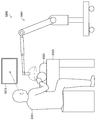
- FIG. 1 is a diagram illustrating an example of a schematic configuration of an endoscopic surgery system 10.
- an endoscopic surgery system 10 includes an endoscope 101, other surgical tools 117, a support arm device 127 that supports the endoscope 101, and various devices for endoscopic surgery. And a cart 137 on which is mounted.
- trocars 125a to 125d are punctured into the abdominal wall. Then, the lens barrel 103 of the endoscope 101 and other surgical tools 117 are inserted into the body cavity of the patient 171 from the trocars 125a to 125d.
- an insufflation tube 119, an energy treatment tool 121, and forceps 123 are inserted into the body cavity of the patient 171.
- the energy treatment device 121 is a treatment device that performs incision and peeling of a tissue, sealing of a blood vessel, or the like by a high-frequency current or ultrasonic vibration.
- the illustrated surgical tool 117 is merely an example, and as the surgical tool 117, various surgical tools generally used in endoscopic surgery, such as a lever and a retractor, may be used.
- the image of the surgical site in the body cavity of the patient 171 captured by the endoscope 101 is displayed on the display device 141.
- the surgeon 167 performs a treatment such as excision of the affected part using the energy treatment tool 121 and the forceps 123 while viewing the image of the surgical part displayed on the display device 141 in real time.
- the pneumoperitoneum tube 119, the energy treatment device 121, and the forceps 123 are supported by an operator 167 or an assistant during the operation.
- the support arm device 127 includes an arm portion 131 extending from the base portion 129.
- the arm unit 131 includes joint units 133a, 133b, and 133c and links 135a and 135b, and is driven by control from the arm control device 145.
- the endoscope 101 is supported by the arm part 131, and its position and posture are controlled. Thereby, the stable position fixing of the endoscope 101 can be realized.
- the endoscope 101 includes a lens barrel 103 in which a region having a predetermined length from the distal end is inserted into the body cavity of the patient 171, and a camera head 105 connected to the proximal end of the lens barrel 103.
- a lens barrel 103 in which a region having a predetermined length from the distal end is inserted into the body cavity of the patient 171, and a camera head 105 connected to the proximal end of the lens barrel 103.
- an endoscope 101 configured as a so-called rigid mirror having a rigid barrel 103 is illustrated, but the endoscope 101 is configured as a so-called flexible mirror having a flexible barrel 103. Also good.
- An opening into which an objective lens is fitted is provided at the tip of the lens barrel 103.
- a light source device 143 is connected to the endoscope 101, and light generated by the light source device 143 is guided to the tip of the lens barrel by a light guide extending inside the lens barrel 103, and the objective 101 Irradiation is performed toward the observation target in the body cavity of the patient 171 through the lens.
- the endoscope 101 may be a direct endoscope, a perspective mirror, or a side endoscope.
- An optical system and an image sensor are provided inside the camera head 105, and reflected light (observation light) from the observation target is condensed on the image sensor by the optical system. Observation light is photoelectrically converted by the imaging element, and an electrical signal corresponding to the observation light, that is, an image signal corresponding to the observation image is generated.
- the image signal is transmitted to a camera control unit (CCU: Camera Control Unit) 139 as RAW data.
- the camera head 105 has a function of adjusting the magnification and the focal length by appropriately driving the optical system.
- a plurality of image sensors may be provided in the camera head 105 in order to cope with, for example, stereoscopic viewing (3D display).
- a plurality of relay optical systems are provided inside the lens barrel 103 in order to guide the observation light to each of the plurality of imaging elements.
- the CCU 139 is an example of a control device according to the present disclosure.
- the CCU 139 is configured by a CPU (Central Processing Unit), a GPU (Graphics Processing Unit), and the like, and comprehensively controls operations of the endoscope 101 and the display device 141.
- the CCU 139 performs various types of image processing for displaying an image based on the image signal, such as development processing (demosaic processing), for example, on the image signal received from the camera head 105.
- the CCU 139 provides the display device 141 with the image signal subjected to the image processing. Further, the CCU 139 transmits a control signal to the camera head 105 to control the driving thereof.
- the control signal can include information regarding imaging conditions such as magnification and focal length.
- the display device 141 displays an image based on an image signal subjected to image processing by the CCU 139 under the control of the CCU 139.
- the endoscope 101 is compatible with high-resolution imaging such as 4K (horizontal pixel number 3840 ⁇ vertical pixel number 2160) or 8K (horizontal pixel number 7680 ⁇ vertical pixel number 4320), and / or 3D display
- high-resolution imaging such as 4K (horizontal pixel number 3840 ⁇ vertical pixel number 2160) or 8K (horizontal pixel number 7680 ⁇ vertical pixel number 4320)
- a display device 141 capable of high-resolution display and / or 3D display can be used.
- a more immersive feeling can be obtained by using a display device 141 having a size of 55 inches or more.
- a plurality of display devices 141 having different resolutions and sizes may be provided depending on applications.
- the light source device 143 is an example of a light source unit in the present disclosure.
- the light source device 143 may be configured by, for example, an LED (light emitting diode) or a laser light source.
- the light source device 143 supplies irradiation light to the endoscope 101 when photographing the surgical site.
- the arm control device 145 is configured by a processor such as a CPU, for example, and operates according to a predetermined program to control driving of the arm portion 131 of the support arm device 127 according to a predetermined control method.
- the input device 147 is an input interface for the endoscopic surgery system 10.
- the user can input various information and instructions to the endoscopic surgery system 10 via the input device 147.
- the user inputs various types of information related to the operation, such as the patient's physical information and information about the surgical technique, via the input device 147.
- the user instructs to drive the arm unit 131 via the input device 147, or to change the imaging conditions (type of irradiation light, magnification, focal length, etc.) by the endoscope 101.
- An instruction or the like for driving the energy treatment device 121 is input.
- the type of the input device 147 is not limited, and the input device 147 may be various known input devices.
- the input device 147 for example, a mouse, a keyboard, a touch panel, a switch, a foot switch 157, and / or a lever can be applied.
- the touch panel may be provided on the display surface of the display device 141.
- the input device 147 is a device worn by the user, such as a glasses-type wearable device or an HMD (Head Mounted Display), for example, and various inputs according to the user's gesture and line of sight detected by these devices. Is done.
- the input device 147 includes a camera capable of detecting a user's movement, and various inputs are performed according to a user's gesture and line of sight detected from an image captured by the camera.
- the input device 147 includes a microphone capable of collecting a user's voice, and various inputs are performed by voice through the microphone.
- the input device 147 is configured to be able to input various kinds of information without contact, so that a user belonging to the clean area (for example, the operator 167) operates the device belonging to the unclean area in a non-contact manner. Is possible.
- the user since the user can operate the device without releasing his / her hand from the surgical tool he / she has, the convenience for the user is improved.
- the treatment instrument control device 149 controls driving of the energy treatment instrument 121 for tissue cauterization, incision, blood vessel sealing, or the like.
- the insufflation apparatus 151 supplies gas into the body cavity through the insufflation tube 119.
- the recorder 153 is a device that can record various types of information related to surgery.
- the printer 155 is a device that can print various types of information related to surgery in various formats such as text, images, or graphs.
- the support arm device 127 includes a base portion 129 that is a base, and an arm portion 131 that extends from the base portion 129.
- the arm part 131 is composed of a plurality of joint parts 133a, 133b, 133c and a plurality of links 135a, 135b connected by the joint part 133b.
- FIG. The structure of the arm part 131 is simplified and shown. Actually, the shape, number and arrangement of the joint portions 133a to 133c and the links 135a and 135b, the direction of the rotation axis of the joint portions 133a to 133c, and the like are appropriately set so that the arm portion 131 has a desired degree of freedom. obtain.
- the arm part 131 can be preferably configured to have a degree of freedom of 6 degrees or more.
- the endoscope 101 can be freely moved within the movable range of the arm portion 131, so that the barrel 103 of the endoscope 101 can be inserted into the body cavity of the patient 171 from a desired direction. It becomes possible.
- the joints 133a to 133c are provided with actuators, and the joints 133a to 133c are configured to be rotatable around a predetermined rotation axis by driving the actuators.
- the drive of the actuator is controlled by the arm control device 145
- the rotation angle of each joint part 133a to 133c is controlled, and the drive of the arm part 131 is controlled.
- the arm control device 145 can control the driving of the arm unit 131 by various known control methods such as force control or position control.
- the arm control device 145 appropriately controls the driving of the arm unit 131 according to the operation input.
- the position and posture of the endoscope 101 may be controlled. With this control, the endoscope 101 at the tip of the arm portion 131 can be moved from an arbitrary position to an arbitrary position and then fixedly supported at the position after the movement.
- the arm part 131 may be operated by what is called a master slave system. In this case, the arm unit 131 can be remotely operated by the user via the input device 147 installed at a location away from the operating room.
- the arm control device 145 When force control is applied, the arm control device 145 receives the external force from the user, and moves the actuators of the joint portions 133a to 133c so that the arm portion 131 moves smoothly according to the external force. You may perform what is called power assist control to drive. Thereby, when the user moves the arm unit 131 while directly touching the arm unit 131, the arm unit 131 can be moved with a relatively light force. Therefore, the endoscope 101 can be moved more intuitively and with a simpler operation, and the convenience for the user can be improved.
- the endoscope 101 is supported by a doctor called a scopist.
- the position of the endoscope 101 can be more reliably fixed without relying on human hands, so that an image of the surgical site can be stably obtained. It becomes possible to perform the operation smoothly.
- the arm control device 145 is not necessarily provided in the cart 137. Further, the arm control device 145 is not necessarily a single device. For example, the arm control device 145 may be provided in each joint portion 133a to 133c of the arm portion 131 of the support arm device 127, and the arm control device 145 cooperates with each other to drive the arm portion 131. Control may be realized.
- the light source device 143 supplies irradiation light when causing the endoscope 101 to photograph a surgical site.
- the light source device 143 includes a white light source configured by, for example, an LED, a laser light source, or a combination thereof.
- the driving of the light source device 143 may be controlled so as to change the intensity of light to be output every predetermined time. Synchronously with the timing of changing the intensity of the light, the drive of the image sensor of the camera head 105 is controlled to acquire images in a time-sharing manner, and the images are synthesized, so that high dynamics without so-called blackout and overexposure are obtained. A range image can be generated.
- the light source device 143 is configured to be able to supply light (visible light and infrared light) in a predetermined wavelength band corresponding to special light observation.
- special light observation for example, by utilizing the wavelength dependence of light absorption in body tissue, the surface of the mucous membrane is irradiated by irradiating light in a narrow band compared to irradiation light (ie, white light) during normal observation.
- narrow band imaging is performed in which a predetermined tissue such as a blood vessel is imaged with high contrast.
- fluorescence observation may be performed in which an image is obtained by fluorescence generated by irradiating excitation light.
- the body tissue is irradiated with excitation light to observe fluorescence from the body tissue (autofluorescence observation), or a reagent such as indocyanine green (ICG) is locally administered to the body tissue and applied to the body tissue.
- a reagent such as indocyanine green (ICG)
- ICG indocyanine green
- the light source device 143 can be configured to be able to supply narrowband light and / or excitation light corresponding to such special light observation.
- FIG. 2 is a block diagram illustrating an example of a functional configuration of the camera head 105 illustrated in FIG.
- the camera head 105 includes a lens unit 107, an imaging unit 109, a driving unit 111, a communication unit 113, and a camera head control unit 115 as functions thereof.
- the camera head 105 and the CCU 139 are connected to each other by a transmission cable (not shown) so as to be able to communicate in both directions.
- the lens unit 107 is an optical system provided at a connection portion with the lens barrel 103. Observation light taken from the tip of the lens barrel 103 is guided to the camera head 105 and enters the lens unit 107.
- the lens unit 107 is configured by combining a plurality of lenses including a zoom lens and a focus lens. The optical characteristics of the lens unit 107 are adjusted so that the observation light is condensed on the light receiving surface of the image sensor of the imaging unit 109. Further, the zoom lens and the focus lens are configured such that their positions on the optical axis are movable in order to adjust the magnification and focus of the captured image.
- the image pickup unit 109 is configured by an image pickup device, and is arranged at the rear stage of the lens unit 107.
- the observation light that has passed through the lens unit 107 is collected on the light receiving surface of the image sensor, and an image signal corresponding to the observation image is generated by photoelectric conversion.
- the image signal generated by the imaging unit 109 is provided to the communication unit 113.
- the image sensor that constitutes the image capturing unit 109 is an image sensor having a rolling shutter mechanism, such as a CMOS, for example, and a sensor capable of color photographing having a Bayer array is used.
- CMOS complementary metal-oxide-semiconductor
- the imaging element for example, an element capable of capturing a high-resolution image of 4K or more may be used.
- the image sensor that configures the image capturing unit 109 is configured to include a pair of image sensors for acquiring right-eye and left-eye image signals corresponding to 3D display. By performing the 3D display, the operator 167 can more accurately grasp the depth of the living tissue in the surgical site.
- the imaging unit 109 is configured as a multi-plate type, a plurality of lens units 107 are also provided corresponding to each imaging element.
- the imaging unit 109 is not necessarily provided in the camera head 105.
- the imaging unit 109 may be provided inside the lens barrel 103 immediately after the objective lens.
- the driving unit 111 is constituted by an actuator, and moves the zoom lens and the focus lens of the lens unit 107 by a predetermined distance along the optical axis under the control of the camera head control unit 115. Thereby, the magnification and the focus of the image captured by the imaging unit 109 can be adjusted as appropriate.
- the communication unit 113 includes a communication device for transmitting and receiving various types of information to and from the CCU 139.
- the communication unit 113 transmits the image signal obtained from the imaging unit 109 to the CCU 139 as RAW data.
- the image signal is preferably transmitted by optical communication.
- the operator 167 performs the operation while observing the state of the affected part with the captured image, so that a moving image of the operated part is displayed in real time as much as possible for a safer and more reliable operation. Because it is required.
- the communication unit 113 is provided with a photoelectric conversion module that converts an electrical signal into an optical signal.
- the image signal is converted into an optical signal by the photoelectric conversion module, and then transmitted to the CCU 139 via a transmission cable.
- the communication unit 113 receives a control signal for controlling the driving of the camera head 105 from the CCU 139.
- the control signal includes, for example, information for designating the frame rate of the captured image, information for designating the exposure value at the time of imaging, and / or information for designating the magnification and focus of the captured image. Contains information about the condition.
- the communication unit 113 provides the received control signal to the camera head control unit 115.
- the control signal from the CCU 139 may also be transmitted by optical communication.
- the communication unit 113 is provided with a photoelectric conversion module that converts an optical signal into an electrical signal.
- the control signal is converted into an electrical signal by the photoelectric conversion module, and then provided to the camera head control unit 115.
- the imaging conditions such as the frame rate, exposure value, magnification, and focus are automatically set by the CCU 139 based on the acquired image signal. That is, a so-called AE (Auto Exposure) function, AF (Auto Focus) function, and AWB (Auto White Balance) function are mounted on the endoscope 101.
- AE Auto Exposure
- AF Automatic Focus
- AWB Automatic White Balance
- the camera head control unit 115 controls driving of the camera head 105 based on a control signal from the CCU 139 received via the communication unit 113. For example, the camera head control unit 115 controls driving of the imaging element of the imaging unit 109 based on information indicating that the frame rate of the captured image is specified and / or information indicating that the exposure at the time of imaging is specified. For example, the camera head control unit 115 appropriately moves the zoom lens and the focus lens of the lens unit 107 via the driving unit 111 based on information indicating that the magnification and the focus of the captured image are designated.
- the camera head control unit 115 may further have a function of storing information for identifying the lens barrel 103 and the camera head 105.
- the camera head 105 can be resistant to autoclave sterilization by arranging the lens unit 107, the imaging unit 109, and the like in a sealed structure with high airtightness and waterproofness.
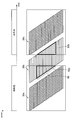
- FIG. 3 is an explanatory diagram showing this problem.
- FIG. 3 shows the time relationship between the exposure timing of the image sensor and the period during which the special light and the white light are respectively irradiated for each frame 30 according to a known technique.
- a frame in which two colors of special light and white light are mixed is generated in some lines 90 in the image sensor.
- the CCU 139 has been created with the above circumstances taken into consideration.
- the CCU 139 determines a period according to the exposure start timing of the lowest line in the image sensor and the exposure end timing of the uppermost line in the image sensor as an irradiation period for irradiating the light source device 143 with light. To do.
- the highest line is an example of the second line in the present disclosure
- the lowest line is an example of the first line in the present disclosure.
- the uppermost line is a line whose exposure starts earlier than the lowermost line in each frame.
- FIG. 4 is a functional block diagram showing a configuration example of the CCU 139 according to the present embodiment.
- the CCU 139 includes a signal processing unit 200, a synchronization control unit 204, and a light source control unit 206.
- the signal processing unit 200 includes a detection unit 202.
- the detection unit 202 is an example of a line determination unit in the present disclosure.
- the detection unit 202 determines the highest line and the lowest line in the imaging device of the imaging unit 109 based on a predetermined reference.
- the predetermined reference may include zoom information (such as zoom magnification) specified by the user.
- the detection unit 202 determines the line numbers of the highest line and the lowest line based on the designated zoom information. For example, when the zoom magnification is increased, the detection unit 202 determines each line number so that the interval between the uppermost line and the lowermost line becomes narrower.
- the detection unit 202 may specify the display area in the image sensor based on the designated zoom information, and may determine the highest line and the lowest line based on the specified display area.
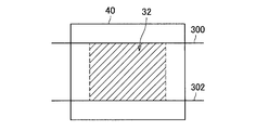
- FIG. 5A is an explanatory diagram showing an example of determining the highest line and the lowest line based on the display area 32 specified in the image sensor 40.
- the detection unit 202 determines the upper end of the display area 32 (or a line above the upper end by a predetermined line) as the uppermost line 300 and the lower end of the display area 32. (Or a line below the lower end by a predetermined line) is determined as the lowest line 302.
- the predetermined reference may include scope information of the endoscope 101.
- the scope information may include, for example, information on the ID of the lens barrel 103, the size of the diameter of the lens barrel 103, and / or the shape of the lens barrel 103.
- the detection unit 202 determines each line number so that the interval between the uppermost line and the lowermost line becomes wider as the diameter of the lens barrel 103 is larger.
- the predetermined reference may include information on a mask area in an image captured by the imaging unit 109.
- the mask area is an area (an area corresponding to the vignetting range) around the effective area in the image captured by the imaging unit 109.
- the image to be captured is an image of a surgical site in the body cavity of the patient 171
- the mask area is an area where no in-vivo video is shown, such as the left, right, top and bottom edges of the image.
- the detection unit 202 determines the highest line and the lowest line based on the boundary between the mask area and the effective area.
- FIG. 5B is an explanatory diagram showing an example of determining the highest line and the lowest line based on the mask area information.
- the detection unit 202 first specifies the effective region 34 in the image sensor 40 based on the mask region information. Then, the detection unit 202 determines the upper limit of the identified effective area 34 as the uppermost line 300 and determines the lower limit of the effective area 34 as the lowermost line 302.
- the mask area information may be specified by applying a predetermined image processing technique to an image picked up by the image pickup unit 109, or specified based on scope information of the endoscope 101. Also good. In the latter case, for example, the detection unit 202 may specify the mask region information by specifying the diameter of the lens barrel 103 corresponding to the scope ID of the endoscope 101, or the mask region information is It is registered in the table in association with the scope information, and the detection unit 202 may specify the mask area information using this table.
- the detection unit 202 may determine the highest line and the lowest line based on only one of the predetermined criteria described above, or any two or more of the predetermined criteria described above. The most significant line and the least significant line may be determined based on.
- the detection unit 202 can change the uppermost line and the lowermost line based on a change in the value indicated by the predetermined reference. For example, when it is determined that the zoom magnification has changed, the detection unit 202 changes the highest line and the lowest line based on the zoom magnification after the change. In addition, the detection part 202 can monitor whether the value which the predetermined reference
- the detection unit 202 can perform detection processing on the image signal for performing AE, AF, and AWB.
- the synchronization control unit 204 performs control for synchronizing the timing between the camera head 105 and the light source device 143.
- the synchronization control unit 204 provides a synchronization signal to the camera head 105 and the light source control unit 206.
- This synchronization signal may be a signal that indicates the exposure start timing of the first line in the image sensor in the corresponding frame.
- the light source control unit 206 determines an irradiation period for irradiating light to the light source device 143 based on the synchronization signal provided from the synchronization control unit 204, the highest line determined by the detection unit 202, and the lowest line. . More specifically, the light source control unit 206 determines a period corresponding to the exposure start timing of the lowest line and the exposure end timing of the highest line as the irradiation period.
- the exposure end timing of the uppermost line is the timing when the length of the exposure time of the uppermost line has elapsed from the exposure start timing of the uppermost line.
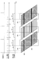
- FIG. 6 is an explanatory diagram showing an example of determining the illumination period L.
- the synchronization signal V shown in FIG. 6 can be provided for each frame by the synchronization control unit 204 as described above.
- the line exposure start signal H is a signal that instructs the start of exposure of each line. As shown in FIG. 6, the line exposure start signal H can be sequentially output for each line with a predetermined time delay from the synchronization signal V of the corresponding frame.
- the output start signal output timing of the uppermost line 300 is described as t1
- the output start signal output timing of the lowermost line 302 is described as b1.
- the light source control unit 206 can determine the length of the irradiation period of each frame to be the same as the length of the irradiation period calculated first.
- the light source control unit 206 recalculates the irradiation period based on the changed highest line and the changed lowest line.
- the light source control unit 206 causes the light source device 143 to irradiate light for the length of the determined irradiation period from the exposure start timing of the lowest line for each frame. In addition, the light source control unit 206 does not cause the light source device 143 to emit light during a period other than the irradiation period. For example, the light source control unit 206 transmits to the light source device 143 an irradiation start signal instructing to start light irradiation at the exposure start timing of the lowest line for each frame, and the exposure end timing of the highest line. To the light source device 143 is transmitted to the light source device 143. According to this control example, since the same amount of light is irradiated on each line in the imaging range (that is, the line between the highest line and the lowest line), the amount of light received differs from line to line. Can be prevented.
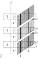
- FIG. 7 is an explanatory diagram showing an example of light irradiation control by the light source control unit 206.
- the light source control unit 206 irradiates the light source device 143 with white light and special light alternately for each frame, that is, performs surface sequential irradiation. Further, as shown in FIG. 7, the light source control unit 206 shortens the length of the irradiation period for each irradiation, and more than the known technique as shown in FIG.
- the light source device 143 is irradiated with white light and special light with high intensity. Thereby, it is possible to prevent white light and special light from being mixed in the imaging range while ensuring a sufficient exposure amount.
- the light source device 143 needs to be a type of light source that can switch the type of irradiation light at a high speed, for example, on the order of several milliseconds. Therefore, as shown in FIG. 8, the light source device 143 needs to use, for example, a laser light source or an LED instead of a xenon light source.
- the light source device 143 is more preferably a laser light source. In this case, as shown in FIG. 8, the light source device 143 can irradiate the observation target with light without unevenness even if the irradiation period is short.
- the camera head 105 can output only the data imaged in the imaging range to the subsequent signal processing.
- the light source control unit 206 can cause the light source device 143 to emit only white light in each frame (instead of the surface sequential irradiation).
- the following two effects can be obtained.
- the observation object is continuously irradiated with white light, the same effect as the flash photography can be obtained.
- the irradiation time is shortened because white light is irradiated with a limited line. And the effect of avoiding the risk of burns is also obtained.
- a clearer image with less motion blur can be taken (compared to the case where no white light is irradiated).
- the signal processing unit 200 performs various types of image processing on the image signal transmitted from the camera head 105 based on the highest line and the lowest line determined by the detection unit 202. For example, the signal processing unit 200 first determines an image processing range from the highest line to the lowest line in the image sensor. Then, the signal processing unit 200 extracts only the image signal corresponding to the determined image processing range from the image signals transmitted from the camera head 105, and performs various types of image processing on the extracted image signal. .
- the image processing includes various known signal processing such as development processing and high image quality processing (band enhancement processing, super-resolution processing, NR (Noise reduction) processing and / or camera shake correction processing), for example. .
- the signal processing unit 200 can perform a process of superimposing the special light captured image and the white light captured image. As a result, an image in which the special light captured image and the white light captured image are superimposed can be displayed on the display device 141.
- FIG. 9 is a flowchart showing an operation example according to the present embodiment. The operation shown in FIG. 9 is executed for each frame.
- the detection unit 202 of the CCU 139 monitors whether or not the uppermost line or the lowermost line in the imaging device of the imaging unit 109 should be changed based on a change in a predetermined reference value. (S101). When it is determined that the highest line and the lowest line should not be changed (S101: No), the CCU 139 performs the process of S109 described later.
- the detection unit 202 has a predetermined reference. Based on (for example, zoom magnification and scope information), the highest line and the lowest line are changed (S103).
- the synchronization control unit 204 provides a synchronization signal to the camera head 105 and the light source control unit 206. Then, the light source control unit 206 identifies the exposure start timing of the highest line and the exposure start timing of the lowest line changed in S103 based on the provided synchronization signal. Then, the light source control unit 206 determines the irradiation period based on the exposure start timing of the uppermost line, the exposure start timing of the lowermost line, and the length of the exposure time (for each line) (S105), and The period is changed to the determined period (S107).
- the imaging unit 109 of the camera head 105 starts exposure based on the provided synchronization signal. Further, the light source control unit 206 causes the light source device 143 to irradiate light (white light or special light) different from the previous frame based on the provided synchronization signal. Thereafter, the camera head 105 transmits the image signal obtained by the imaging unit 109 to the CCU 139 (S109).
- the signal processing unit 200 changes the current image processing range to a range from the highest line to the lowest line changed in S103 (S111).
- the signal processing unit 200 extracts an image signal corresponding to the image processing range set in S111 from the image signal received in S109, and performs various images on the extracted image signal. Processing is performed (S113).
- the CCU 139 has a period between the exposure start timing of the lowest line in the image sensor of the imaging unit 109 and the exposure end timing of the highest line in the image sensor. Is determined as an irradiation period during which the light source device 143 is irradiated with light. For this reason, it is possible to determine an appropriate irradiation period in a scene where light is irradiated during imaging using an imaging element having a rolling shutter mechanism.
- the CCU 139 alternately irradiates the light source device 143 with white light and special light for each frame, and irradiates the light source device 143 with light only during the irradiation period for each frame.
- the generation of mixed color frames can be prevented, so that a decrease in frame rate can be prevented.
- the light source device 143 can be constituted by a laser light source. For this reason, the type of irradiation light can be switched at high speed, and even when the irradiation period is short, light with no unevenness can be irradiated to the observation target. For example, it is possible to prevent the exposure amount from varying between frames.
- the technology according to the present disclosure can be applied to various products.
- the technology according to the present disclosure may be applied to a microscopic surgery system used for so-called microsurgery performed while magnifying and observing a fine part of a patient.
- FIG. 10 is a diagram illustrating an example of a schematic configuration of a microscopic surgery system 5300 to which the technology according to the present disclosure can be applied.
- the microscope operation system 5300 includes a microscope device 5301, a control device 5317, and a display device 5319.
- “user” means any medical staff who uses the microscope surgery system 5300, such as an operator and an assistant.
- the microscope apparatus 5301 includes a microscope unit 5303 for magnifying and observing an observation target (a patient's surgical site), an arm unit 5309 that supports the microscope unit 5303 at the distal end, and a base unit 5315 that supports the proximal end of the arm unit 5309. Have.
- the microscope unit 5303 includes a substantially cylindrical cylindrical part 5305, an imaging unit (not shown) provided inside the cylindrical part 5305, and an operation unit 5307 provided in a partial area on the outer periphery of the cylindrical part 5305. And.
- the microscope unit 5303 is an electronic imaging type microscope unit (so-called video type microscope unit) in which a captured image is electronically captured by the imaging unit.
- a cover glass that protects the internal imaging unit is provided on the opening surface at the lower end of the cylindrical part 5305.
- Light from the observation target (hereinafter also referred to as observation light) passes through the cover glass and enters the imaging unit inside the cylindrical part 5305.
- a light source such as an LED (Light Emitting Diode) may be provided inside the cylindrical portion 5305, and light is emitted from the light source to the observation target through the cover glass during imaging. May be.
- the imaging unit includes an optical system that collects the observation light and an image sensor that receives the observation light collected by the optical system.
- the optical system is configured by combining a plurality of lenses including a zoom lens and a focus lens, and the optical characteristics thereof are adjusted so that the observation light is imaged on the light receiving surface of the image sensor.
- the imaging element receives the observation light and photoelectrically converts it to generate a signal corresponding to the observation light, that is, an image signal corresponding to the observation image.
- an element having a Bayer array capable of color photography is used.
- the image sensor may be various known image sensors such as a CMOS (Complementary Metal Oxide Semiconductor) image sensor or a CCD (Charge Coupled Device) image sensor.
- the image signal generated by the image sensor is transmitted to the control device 5317 as RAW data.
- the transmission of the image signal may be preferably performed by optical communication.
- the surgeon performs the operation while observing the state of the affected area with the captured image.
- the moving image of the surgical site should be displayed in real time as much as possible. Because it is.
- a captured image can be displayed with low latency.
- the imaging unit may have a drive mechanism that moves the zoom lens and focus lens of the optical system along the optical axis. By appropriately moving the zoom lens and the focus lens by the drive mechanism, the enlargement magnification of the captured image and the focal length at the time of imaging can be adjusted.
- the imaging unit may be equipped with various functions that can be generally provided in an electronic imaging microscope unit, such as an AE (Auto Exposure) function and an AF (Auto Focus) function.
- the imaging unit may be configured as a so-called single-plate imaging unit having one imaging element, or may be configured as a so-called multi-plate imaging unit having a plurality of imaging elements.
- image signals corresponding to RGB may be generated by each imaging element, and a color image may be obtained by combining them.
- the said imaging part may be comprised so that it may have a pair of image sensor for each acquiring the image signal for right eyes and left eyes corresponding to a stereoscopic vision (3D display). By performing the 3D display, the surgeon can more accurately grasp the depth of the living tissue in the surgical site.
- a plurality of optical systems can be provided corresponding to each imaging element.
- the operation unit 5307 is configured by, for example, a cross lever or a switch, and is an input unit that receives a user operation input.
- the user can input an instruction to change the magnification of the observation image and the focal length to the observation target via the operation unit 5307.
- the magnification ratio and the focal length can be adjusted by appropriately moving the zoom lens and the focus lens by the drive mechanism of the imaging unit in accordance with the instruction.
- the user can input an instruction to switch the operation mode (all-free mode and fixed mode described later) of the arm unit 5309 via the operation unit 5307.
- the operation unit 5307 may be provided at a position where the user can easily operate with a finger while holding the tubular portion 5305 so that the operation portion 5307 can be operated while the tubular portion 5305 is moved. preferable.
- the arm portion 5309 is configured by a plurality of links (first link 5313a to sixth link 5313f) being connected to each other by a plurality of joint portions (first joint portion 5311a to sixth joint portion 5311f). Is done.
- the first joint portion 5311a has a substantially cylindrical shape, and at its tip (lower end), the upper end of the cylindrical portion 5305 of the microscope portion 5303 is a rotation axis (first axis) parallel to the central axis of the cylindrical portion 5305. O 1 ) is supported so as to be rotatable around.
- the first joint portion 5311a may be configured such that the first axis O 1 coincides with the optical axis of the imaging unit of the microscope unit 5303.
- the first link 5313a fixedly supports the first joint portion 5311a at the tip. More specifically, the first link 5313a is a rod-shaped member having a substantially L-shaped, while stretching in the direction in which one side of the front end side is perpendicular to the first axis O 1, the end portion of the one side is first It connects to the 1st joint part 5311a so that it may contact
- the second joint portion 5311b is connected to the end portion on the other side of the substantially L-shaped base end side of the first link 5313a.
- the second joint portion 5311b has a substantially cylindrical shape, and at the tip thereof, the base end of the first link 5313a can be rotated around a rotation axis (second axis O 2 ) orthogonal to the first axis O 1. To support.
- the distal end of the second link 5313b is fixedly connected to the proximal end of the second joint portion 5311b.
- the second link 5313b is a rod-shaped member having a substantially L-shaped, while stretching in the direction in which one side of the front end side is perpendicular to the second axis O 2, the ends of the one side of the second joint portion 5311b Fixedly connected to the proximal end.
- a third joint portion 5311c is connected to the other side of the base end side of the substantially L-shaped base of the second link 5313b.
- the third joint portion 5311c has a substantially cylindrical shape, and at its tip, the base end of the second link 5313b is a rotation axis (third axis O 3) orthogonal to the first axis O 1 and the second axis O 2. ) Support so that it can rotate around.
- the distal end of the third link 5313c is fixedly connected to the proximal end of the third joint portion 5311c.
- the microscope unit 5303 is moved so as to change the position of the microscope unit 5303 in the horizontal plane by rotating the configuration on the distal end side including the microscope unit 5303 around the second axis O 2 and the third axis O 3. Can be made. That is, by controlling the rotation around the second axis O 2 and the third axis O 3 , the field of view of the captured image can be moved in a plane.
- the third link 5313c is configured such that the distal end side thereof has a substantially cylindrical shape, and the proximal end of the third joint portion 5311c has substantially the same central axis at the distal end of the cylindrical shape. Fixedly connected.
- the proximal end side of the third link 5313c has a prismatic shape, and the fourth joint portion 5311d is connected to the end portion thereof.
- the fourth joint portion 5311d has a substantially cylindrical shape, and at the tip thereof, the base end of the third link 5313c can be rotated around a rotation axis (fourth axis O 4 ) orthogonal to the third axis O 3. To support.
- the distal end of the fourth link 5313d is fixedly connected to the proximal end of the fourth joint portion 5311d.
- Fourth link 5313d is a rod-shaped member extending substantially in a straight line, while stretched so as to be orthogonal to the fourth axis O 4, the end of the tip side of the substantially cylindrical shape of the fourth joint portion 5311d It is fixedly connected to the fourth joint portion 5311d so as to abut.
- the fifth joint portion 5311e is connected to the base end of the fourth link 5313d.
- the fifth joint portion 5311e has a substantially cylindrical shape, and on the distal end side thereof, the base end of the fourth link 5313d can be rotated around a rotation axis (fifth axis O 5 ) parallel to the fourth axis O 4. To support.
- the distal end of the fifth link 5313e is fixedly connected to the proximal end of the fifth joint portion 5311e.
- the fourth axis O 4 and the fifth axis O 5 are rotation axes that can move the microscope unit 5303 in the vertical direction.
- the fifth link 5313e includes a first member having a substantially L shape in which one side extends in the vertical direction and the other side extends in the horizontal direction, and a portion extending in the horizontal direction of the first member in a vertically downward direction. A rod-shaped second member that extends is combined.
- the proximal end of the fifth joint portion 5311e is fixedly connected in the vicinity of the upper end of the portion of the fifth link 5313e extending in the vertical direction of the first member.
- the sixth joint portion 5311f is connected to the proximal end (lower end) of the second member of the fifth link 5313e.
- the sixth joint portion 5311f has a substantially cylindrical shape, and supports the base end of the fifth link 5313e on the distal end side thereof so as to be rotatable about a rotation axis (sixth axis O 6 ) parallel to the vertical direction. .
- the distal end of the sixth link 5313f is fixedly connected to the proximal end of the sixth joint portion 5311f.
- the sixth link 5313f is a rod-like member extending in the vertical direction, and its base end is fixedly connected to the upper surface of the base portion 5315.
- the rotatable range of the first joint portion 5311a to the sixth joint portion 5311f is appropriately set so that the microscope portion 5303 can perform a desired movement.
- a total of 6 degrees of freedom of translational 3 degrees of freedom and 3 degrees of freedom of rotation can be realized with respect to the movement of the microscope unit 5303.
- the position and posture of the microscope unit 5303 can be freely controlled within the movable range of the arm unit 5309. It becomes possible. Therefore, the surgical site can be observed from any angle, and the surgery can be performed more smoothly.
- the configuration of the arm portion 5309 shown in the figure is merely an example, and the number and shape (length) of the links constituting the arm portion 5309, the number of joint portions, the arrangement position, the direction of the rotation axis, and the like are desired. It may be designed as appropriate so that the degree can be realized.
- the arm unit 5309 in order to freely move the microscope unit 5303, the arm unit 5309 is preferably configured to have six degrees of freedom, but the arm unit 5309 has a greater degree of freedom (ie, redundant freedom). Degree).
- the arm unit 5309 can change the posture of the arm unit 5309 while the position and posture of the microscope unit 5303 are fixed. Therefore, for example, control that is more convenient for the operator can be realized, such as controlling the posture of the arm unit 5309 so that the arm unit 5309 does not interfere with the field of view of the operator who views the display device 5319.
- the first joint portion 5311a to the sixth joint portion 5311f may be provided with actuators mounted with a drive mechanism such as a motor, an encoder for detecting a rotation angle at each joint portion, and the like. Then, the drive of each actuator provided in the first joint portion 5311a to the sixth joint portion 5311f is appropriately controlled by the control device 5317, whereby the posture of the arm portion 5309, that is, the position and posture of the microscope portion 5303 can be controlled. . Specifically, the control device 5317 grasps the current posture of the arm unit 5309 and the current position and posture of the microscope unit 5303 based on information about the rotation angle of each joint unit detected by the encoder. Can do.
- a drive mechanism such as a motor, an encoder for detecting a rotation angle at each joint portion, and the like.
- the control device 5317 calculates the control value (for example, rotation angle or generated torque) for each joint unit that realizes the movement of the microscope unit 5303 according to the operation input from the user, using the grasped information. And the drive mechanism of each joint part is driven according to the said control value.
- the control method of the arm unit 5309 by the control device 5317 is not limited, and various known control methods such as force control or position control may be applied.
- the drive of the arm unit 5309 is appropriately controlled by the control device 5317 according to the operation input, and the position and posture of the microscope unit 5303 are controlled. May be.
- the microscope unit 5303 can be moved from an arbitrary position to an arbitrary position and then fixedly supported at the position after the movement.
- an input device that can be operated even if the operator has a surgical tool in his / her hand.
- non-contact operation input may be performed based on gesture detection or gaze detection using a wearable device or a camera provided in an operating room.
- the arm portion 5309 may be operated by a so-called master slave method.
- the arm unit 5309 can be remotely operated by the user via an input device installed at a location away from the operating room.
- the actuators of the first joint portion 5311a to the sixth joint portion 5311f are driven so that the external force from the user is received and the arm portion 5309 moves smoothly according to the external force.
- so-called power assist control may be performed.
- the driving of the arm portion 5309 may be controlled so as to perform a pivoting operation.
- the pivoting operation is an operation of moving the microscope unit 5303 so that the optical axis of the microscope unit 5303 always faces a predetermined point in space (hereinafter referred to as a pivot point). According to the pivot operation, the same observation position can be observed from various directions, so that more detailed observation of the affected area is possible.
- the pivot operation is performed in a state where the distance between the microscope unit 5303 and the pivot point is fixed. In this case, the distance between the microscope unit 5303 and the pivot point may be adjusted to a fixed focal length of the microscope unit 5303.
- the microscope unit 5303 moves on a hemispherical surface (schematically illustrated in FIG. 10) having a radius corresponding to the focal length centered on the pivot point, and is clear even if the observation direction is changed. A captured image is obtained.
- the microscope unit 5303 is configured to be adjustable in focal length
- the pivot operation may be performed in a state where the distance between the microscope unit 5303 and the pivot point is variable.
- the control device 5317 calculates the distance between the microscope unit 5303 and the pivot point based on the information about the rotation angle of each joint unit detected by the encoder, and based on the calculation result, the microscope 5317
- the focal length of the unit 5303 may be automatically adjusted.
- the microscope unit 5303 is provided with an AF function
- the focal length may be automatically adjusted by the AF function every time the distance between the microscope unit 5303 and the pivot point is changed by the pivot operation. .
- the first joint portion 5311a to the sixth joint portion 5311f may be provided with a brake that restrains the rotation thereof.
- the operation of the brake can be controlled by the control device 5317.
- the control device 5317 activates the brake of each joint unit. Accordingly, since the posture of the arm unit 5309, that is, the position and posture of the microscope unit 5303 can be fixed without driving the actuator, power consumption can be reduced.
- the control device 5317 may release the brake of each joint unit and drive the actuator according to a predetermined control method.
- Such an operation of the brake can be performed according to an operation input by the user via the operation unit 5307 described above.
- the user wants to move the position and posture of the microscope unit 5303, the user operates the operation unit 5307 to release the brakes of the joint units.
- the operation mode of the arm part 5309 shifts to a mode (all free mode) in which the rotation at each joint part can be freely performed.
- the user wants to fix the position and posture of the microscope unit 5303, the user operates the operation unit 5307 to activate the brakes of the joint units.
- the operation mode of the arm part 5309 shifts to a mode (fixed mode) in which rotation at each joint part is restricted.
- the control device 5317 comprehensively controls the operation of the microscope operation system 5300 by controlling the operations of the microscope device 5301 and the display device 5319.
- the control device 5317 controls the driving of the arm portion 5309 by operating the actuators of the first joint portion 5311a to the sixth joint portion 5311f according to a predetermined control method.
- the control device 5317 changes the operation mode of the arm portion 5309 by controlling the brake operation of the first joint portion 5311a to the sixth joint portion 5311f.
- the control device 5317 performs various kinds of signal processing on the image signal acquired by the imaging unit of the microscope unit 5303 of the microscope device 5301 to generate image data for display and display the image data. It is displayed on the device 5319.
- the signal processing for example, development processing (demosaic processing), high image quality processing (band enhancement processing, super-resolution processing, NR (Noise reduction) processing and / or camera shake correction processing, etc.) and / or enlargement processing (that is, Various known signal processing such as electronic zoom processing may be performed.
- communication between the control device 5317 and the microscope unit 5303 and communication between the control device 5317 and the first joint unit 5311a to the sixth joint unit 5311f may be wired communication or wireless communication.
- wired communication communication using electrical signals may be performed, or optical communication may be performed.
- a transmission cable used for wired communication can be configured as an electric signal cable, an optical fiber, or a composite cable thereof depending on the communication method.
- wireless communication there is no need to lay a transmission cable in the operating room, so that the situation where the transmission cable prevents the medical staff from moving in the operating room can be eliminated.
- the control device 5317 may be a processor such as a CPU (Central Processing Unit) or a GPU (Graphics Processing Unit), or a microcomputer or a control board in which a processor and a storage element such as a memory are mixedly mounted.
- the various functions described above can be realized by the processor of the control device 5317 operating according to a predetermined program.
- the control device 5317 is provided as a separate device from the microscope device 5301, but the control device 5317 is installed inside the base portion 5315 of the microscope device 5301 and integrated with the microscope device 5301. May be configured.
- the control device 5317 may be configured by a plurality of devices.
- a microcomputer, a control board, and the like are arranged in the microscope unit 5303 and the first joint unit 5311a to the sixth joint unit 5311f of the arm unit 5309, and these are communicably connected to each other. Similar functions may be realized.
- the display device 5319 is provided in the operating room, and displays an image corresponding to the image data generated by the control device 5317 under the control of the control device 5317. In other words, the display device 5319 displays an image of the surgical part taken by the microscope unit 5303.
- the display device 5319 may display various types of information related to the surgery, such as information about the patient's physical information and the surgical technique, for example, instead of or together with the image of the surgical site. In this case, the display of the display device 5319 may be switched as appropriate by a user operation.
- a plurality of display devices 5319 may be provided, and each of the plurality of display devices 5319 may display an image of the surgical site and various types of information regarding surgery.
- various known display devices such as a liquid crystal display device or an EL (Electro Luminescence) display device may be applied.
- FIG. 11 is a diagram showing a state of surgery using the microscope surgery system 5300 shown in FIG.
- a state in which an operator 5321 performs an operation on a patient 5325 on a patient bed 5323 using a microscope operation system 5300 is schematically shown.
- the control device 5317 is omitted from the configuration of the microscope surgery system 5300 and the microscope device 5301 is illustrated in a simplified manner.
- an image of the surgical part taken by the microscope apparatus 5301 is enlarged and displayed on the display device 5319 installed on the wall of the operating room using the microscope operation system 5300.
- the display device 5319 is installed at a position facing the surgeon 5321, and the surgeon 5321 observes the state of the surgical site by an image projected on the display device 5319, for example, the surgical site such as excision of the affected site.
- Various treatments are performed on
- the microscopic surgery system 5300 to which the technology according to the present disclosure can be applied has been described.
- the microscopic surgery system 5300 has been described as an example, but a system to which the technology according to the present disclosure can be applied is not limited to such an example.
- the microscope apparatus 5301 can function as a support arm apparatus that supports another observation apparatus or another surgical tool instead of the microscope unit 5303 at the tip.
- an endoscope can be applied.
- the other surgical tools forceps, a lever, an insufflation tube for insufflation, or an energy treatment instrument for incising a tissue or sealing a blood vessel by cauterization can be applied.
- the technology according to the present disclosure may be applied to a support arm device that supports a configuration other than the microscope unit.
- the configuration according to the present embodiment is not limited to the example shown in FIG.
- the light source control unit 206 may be provided in the light source device 143 instead of the CCU 139.
- the CCU 139 can provide the determined line numbers of the highest line and the lowest line to the light source device 143.
- the light source device 143 (the light source control unit 206 in the light source device 143) can control light irradiation based on the provided line numbers of the uppermost line and the lowermost line.
- each step in the operation of the above-described embodiment does not necessarily have to be processed in the order described.
- the steps may be processed by changing the order as appropriate.
- Each step may be processed in parallel or individually instead of being processed in time series. Further, some of the described steps may be omitted, or another step may be further added.
- hardware such as processors, such as CPU and GPU, and memory elements, such as a memory, is made to exhibit a function equivalent to each structure of CCU139 by this embodiment mentioned above.
- a computer program can also be provided.
- a recording medium on which the computer program is recorded is also provided.
- a light source control unit that determines a period according to the exposure start timing of the first line in the image sensor and the exposure end timing of the second line in the image sensor as an irradiation period for irradiating the light source unit with light; With The control device, wherein the second line is a line whose exposure start in one frame is earlier than the first line.
- the light source control unit determines a period between an exposure start timing of the first line and an exposure end timing of the second line as the irradiation period.
- the exposure end timing of the second line is a timing at which an exposure time of the second line has elapsed from an exposure start timing of the second line.
- the light source control unit determines the length of the irradiation period for each frame to be the same length.
- the control device further includes a line determination unit that determines the first line and the second line based on a predetermined criterion. apparatus.
- the line determination unit changes the first line or the second line based on a change in a value indicated by the predetermined criterion, When the first line or the second line is changed, the light source control unit determines the length of the irradiation period based on the changed first line and the changed second line.
- the predetermined reference includes scope information of an endoscope having the imaging element.
- the control device according to any one of (5) to (8), wherein the predetermined reference includes information on a mask region in an image captured by an imaging unit having the imaging element.
- the information on the mask area is specified based on scope information of an endoscope including the imaging unit.
- the information on the mask area is specified by predetermined image processing on an image captured by the imaging unit.
- the light source control unit further causes the light source unit to emit light during the irradiation period for each frame.
- the light source control unit does not cause the light source unit to emit light during a period other than the irradiation period.
- the control device (14) The control device according to (13), wherein the light source control unit causes the light source unit to alternately emit the first light and the second light for each frame.
- the first light is white light;
- the control device (14), wherein the second light is special light.
- the said light source control part is a control apparatus as described in said (13) which irradiates the same kind of light to the said light source part for every flame
- the control device according to any one of (1) to (17), wherein the light source unit is a semiconductor light source.
- a light source unit An imaging unit; An irradiation period for irradiating the light source unit with light during a period corresponding to the exposure start timing of the first line in the image sensor included in the image sensor and the exposure end timing of the second line in the image sensor
- a light source control unit determined as: With The control system in which the second line is a line whose exposure start in one frame is earlier than the first line. (20) The processor determines a period corresponding to the exposure start timing of the first line in the image sensor and the exposure end timing of the second line in the image sensor as an irradiation period for irradiating the light source unit with light; Including The control method, wherein the second line is a line whose exposure start in one frame is earlier than the first line.
Landscapes
- Health & Medical Sciences (AREA)
- Life Sciences & Earth Sciences (AREA)
- Surgery (AREA)
- Physics & Mathematics (AREA)
- Engineering & Computer Science (AREA)
- Optics & Photonics (AREA)
- Radiology & Medical Imaging (AREA)
- Veterinary Medicine (AREA)
- Biophysics (AREA)
- Pathology (AREA)
- Nuclear Medicine, Radiotherapy & Molecular Imaging (AREA)
- Public Health (AREA)
- Biomedical Technology (AREA)
- Heart & Thoracic Surgery (AREA)
- Medical Informatics (AREA)
- Molecular Biology (AREA)
- Animal Behavior & Ethology (AREA)
- General Health & Medical Sciences (AREA)
- Signal Processing (AREA)
- Multimedia (AREA)
- General Physics & Mathematics (AREA)
- Endoscopes (AREA)
- Instruments For Viewing The Inside Of Hollow Bodies (AREA)
Abstract
Le problème abordé par la présente invention est de pourvoir à un dispositif, à un système, et à un procédé de commande qui peuvent déterminer de manière appropriée une période d'exposition pendant laquelle l'émission de lumière se produit simultanément à l'imagerie. La solution selon l'invention porte sur un dispositif de commande qui comprend une unité de commande de source lumineuse qui détermine qu'une période correspondant à l'intervalle entre le début de l'exposition d'une première ligne d'un élément d'imagerie et la fin de l'exposition d'une seconde ligne de l'élément d'imagerie est une période d'exposition pendant laquelle la lumière est émise par une unité de source lumineuse, la seconde ligne étant la ligne pour laquelle l'exposition dans un cadre débute plus tôt que pour la première ligne.
Priority Applications (1)
| Application Number | Priority Date | Filing Date | Title |
|---|---|---|---|
| US16/308,525 US20190154953A1 (en) | 2016-06-23 | 2017-03-24 | Control apparatus, control system, and control method |
Applications Claiming Priority (2)
| Application Number | Priority Date | Filing Date | Title |
|---|---|---|---|
| JP2016-124423 | 2016-06-23 | ||
| JP2016124423 | 2016-06-23 |
Publications (1)
| Publication Number | Publication Date |
|---|---|
| WO2017221491A1 true WO2017221491A1 (fr) | 2017-12-28 |
Family
ID=60783993
Family Applications (1)
| Application Number | Title | Priority Date | Filing Date |
|---|---|---|---|
| PCT/JP2017/011939 Ceased WO2017221491A1 (fr) | 2016-06-23 | 2017-03-24 | Dispositif, système et procédé de commande |
Country Status (2)
| Country | Link |
|---|---|
| US (1) | US20190154953A1 (fr) |
| WO (1) | WO2017221491A1 (fr) |
Cited By (4)
| Publication number | Priority date | Publication date | Assignee | Title |
|---|---|---|---|---|
| JP2020068965A (ja) * | 2018-10-30 | 2020-05-07 | ソニー・オリンパスメディカルソリューションズ株式会社 | 医療用観察装置、および医療用観察システム |
| JP2020137614A (ja) * | 2019-02-27 | 2020-09-03 | Hoya株式会社 | 電子内視鏡システム |
| JP2022517128A (ja) * | 2019-01-17 | 2022-03-04 | ストライカー コーポレイション | ローリングシャッタイメージャを使用する医療用撮像のためのシステムおよび方法 |
| US12003861B2 (en) | 2020-12-30 | 2024-06-04 | Stryker Corporation | Systems and methods for mitigating artifacts in medical imaging |
Families Citing this family (1)
| Publication number | Priority date | Publication date | Assignee | Title |
|---|---|---|---|---|
| JP7634425B2 (ja) | 2021-05-20 | 2025-02-21 | Hoya株式会社 | 電子内視鏡システム |
Citations (3)
| Publication number | Priority date | Publication date | Assignee | Title |
|---|---|---|---|---|
| JP2015070937A (ja) * | 2013-10-03 | 2015-04-16 | 富士フイルム株式会社 | 内視鏡装置 |
| WO2015114906A1 (fr) * | 2014-01-29 | 2015-08-06 | オリンパス株式会社 | Système d'imagerie et dispositif d'imagerie |
| JP2015160013A (ja) * | 2014-02-27 | 2015-09-07 | 富士フイルム株式会社 | 内視鏡システム、内視鏡システム用プロセッサ装置、内視鏡システムの作動方法、内視鏡システム用プロセッサ装置の作動方法 |
-
2017
- 2017-03-24 WO PCT/JP2017/011939 patent/WO2017221491A1/fr not_active Ceased
- 2017-03-24 US US16/308,525 patent/US20190154953A1/en not_active Abandoned
Patent Citations (3)
| Publication number | Priority date | Publication date | Assignee | Title |
|---|---|---|---|---|
| JP2015070937A (ja) * | 2013-10-03 | 2015-04-16 | 富士フイルム株式会社 | 内視鏡装置 |
| WO2015114906A1 (fr) * | 2014-01-29 | 2015-08-06 | オリンパス株式会社 | Système d'imagerie et dispositif d'imagerie |
| JP2015160013A (ja) * | 2014-02-27 | 2015-09-07 | 富士フイルム株式会社 | 内視鏡システム、内視鏡システム用プロセッサ装置、内視鏡システムの作動方法、内視鏡システム用プロセッサ装置の作動方法 |
Cited By (11)
| Publication number | Priority date | Publication date | Assignee | Title |
|---|---|---|---|---|
| JP2020068965A (ja) * | 2018-10-30 | 2020-05-07 | ソニー・オリンパスメディカルソリューションズ株式会社 | 医療用観察装置、および医療用観察システム |
| JP7277108B2 (ja) | 2018-10-30 | 2023-05-18 | ソニー・オリンパスメディカルソリューションズ株式会社 | 医療用観察システム、および医療用観察システムの作動方法 |
| JP2023109802A (ja) * | 2018-10-30 | 2023-08-08 | ソニー・オリンパスメディカルソリューションズ株式会社 | 医療用制御装置、および医療用観察システム |
| JP2022517128A (ja) * | 2019-01-17 | 2022-03-04 | ストライカー コーポレイション | ローリングシャッタイメージャを使用する医療用撮像のためのシステムおよび方法 |
| JP7603589B2 (ja) | 2019-01-17 | 2024-12-20 | ストライカー コーポレイション | ローリングシャッタイメージャを使用する医療用撮像のためのシステムおよび方法 |
| US12201270B2 (en) | 2019-01-17 | 2025-01-21 | Stryker Corporation | Systems and methods for medical imaging using a rolling shutter imager |
| US12201271B2 (en) | 2019-01-17 | 2025-01-21 | Stryker Corporation | Systems and methods for medical imaging using a rolling shutter imager |
| JP2020137614A (ja) * | 2019-02-27 | 2020-09-03 | Hoya株式会社 | 電子内視鏡システム |
| JP7610343B2 (ja) | 2019-02-27 | 2025-01-08 | Hoya株式会社 | 電子内視鏡システム |
| US12003861B2 (en) | 2020-12-30 | 2024-06-04 | Stryker Corporation | Systems and methods for mitigating artifacts in medical imaging |
| US12289533B2 (en) | 2020-12-30 | 2025-04-29 | Stryker Corporation | Systems and methods for mitigating artifacts in medical imaging |
Also Published As
| Publication number | Publication date |
|---|---|
| US20190154953A1 (en) | 2019-05-23 |
Similar Documents
| Publication | Publication Date | Title |
|---|---|---|
| CN112584743A (zh) | 医疗系统、信息处理装置和信息处理方法 | |
| US11463629B2 (en) | Medical system, medical apparatus, and control method | |
| JP7095693B2 (ja) | 医療用観察システム | |
| JP2018075218A (ja) | 医療用支持アーム及び医療用システム | |
| WO2018088113A1 (fr) | Actionneur d'entraînement d'articulation et système médical | |
| JPWO2019239942A1 (ja) | 手術用観察装置、手術用観察方法、手術用光源装置、及び手術用の光照射方法 | |
| WO2017221491A1 (fr) | Dispositif, système et procédé de commande | |
| WO2022004250A1 (fr) | Système médical, dispositif de traitement d'informations et procédé de traitement d'informations | |
| JPWO2018142993A1 (ja) | 発光制御装置、発光制御方法、プログラム、発光装置、および撮像装置 | |
| WO2021256168A1 (fr) | Système de traitement d'image médicale, dispositif de commande d'image chirurgicale et procédé de commande d'image chirurgicale | |
| US11553838B2 (en) | Endoscope and arm system | |
| JPWO2020045014A1 (ja) | 医療システム、情報処理装置及び情報処理方法 | |
| JP7544033B2 (ja) | 医療システム、情報処理装置及び情報処理方法 | |
| WO2020203225A1 (fr) | Système médical, dispositif et procédé de traitement d'informations | |
| US20220022728A1 (en) | Medical system, information processing device, and information processing method | |
| WO2020084917A1 (fr) | Système médical et procédé de traitement d'informations | |
| WO2018043205A1 (fr) | Dispositif de traitement d'image médicale, procédé de traitement d'image médicale, et programme | |
| JPWO2019202860A1 (ja) | 医療用システム、接続構造、及び接続方法 | |
| JPWO2020050187A1 (ja) | 医療システム、情報処理装置及び情報処理方法 | |
| WO2021044900A1 (fr) | Système opératoire, dispositif de traitement d'image, procédé de traitement d'image et programme |
Legal Events
| Date | Code | Title | Description |
|---|---|---|---|
| 121 | Ep: the epo has been informed by wipo that ep was designated in this application |
Ref document number: 17814963 Country of ref document: EP Kind code of ref document: A1 |
|
| NENP | Non-entry into the national phase |
Ref country code: DE |
|
| 122 | Ep: pct application non-entry in european phase |
Ref document number: 17814963 Country of ref document: EP Kind code of ref document: A1 |
|
| NENP | Non-entry into the national phase |
Ref country code: JP |