WO2017221976A1 - Dispositif d'aspiration et dispositif de commande - Google Patents
Dispositif d'aspiration et dispositif de commande Download PDFInfo
- Publication number
- WO2017221976A1 WO2017221976A1 PCT/JP2017/022850 JP2017022850W WO2017221976A1 WO 2017221976 A1 WO2017221976 A1 WO 2017221976A1 JP 2017022850 W JP2017022850 W JP 2017022850W WO 2017221976 A1 WO2017221976 A1 WO 2017221976A1
- Authority
- WO
- WIPO (PCT)
- Prior art keywords
- revolution
- suction port
- suction
- duct
- air
- Prior art date
- Legal status (The legal status is an assumption and is not a legal conclusion. Google has not performed a legal analysis and makes no representation as to the accuracy of the status listed.)
- Ceased
Links
Images














Classifications
-
- F—MECHANICAL ENGINEERING; LIGHTING; HEATING; WEAPONS; BLASTING
- F24—HEATING; RANGES; VENTILATING
- F24F—AIR-CONDITIONING; AIR-HUMIDIFICATION; VENTILATION; USE OF AIR CURRENTS FOR SCREENING
- F24F7/00—Ventilation
- F24F7/04—Ventilation with ducting systems, e.g. by double walls; with natural circulation
- F24F7/06—Ventilation with ducting systems, e.g. by double walls; with natural circulation with forced air circulation, e.g. by fan positioning of a ventilator in or against a conduit
- F24F7/065—Ventilation with ducting systems, e.g. by double walls; with natural circulation with forced air circulation, e.g. by fan positioning of a ventilator in or against a conduit fan combined with single duct; mounting arrangements of a fan in a duct
-
- B—PERFORMING OPERATIONS; TRANSPORTING
- B04—CENTRIFUGAL APPARATUS OR MACHINES FOR CARRYING-OUT PHYSICAL OR CHEMICAL PROCESSES
- B04C—APPARATUS USING FREE VORTEX FLOW, e.g. CYCLONES
- B04C3/00—Apparatus in which the axial direction of the vortex flow following a screw-thread type line remains unchanged ; Devices in which one of the two discharge ducts returns centrally through the vortex chamber, a reverse-flow vortex being prevented by bulkheads in the central discharge duct
- B04C3/06—Construction of inlets or outlets to the vortex chamber
-
- A—HUMAN NECESSITIES
- A47—FURNITURE; DOMESTIC ARTICLES OR APPLIANCES; COFFEE MILLS; SPICE MILLS; SUCTION CLEANERS IN GENERAL
- A47L—DOMESTIC WASHING OR CLEANING; SUCTION CLEANERS IN GENERAL
- A47L9/00—Details or accessories of suction cleaners, e.g. mechanical means for controlling the suction or for effecting pulsating action; Storing devices specially adapted to suction cleaners or parts thereof; Carrying-vehicles specially adapted for suction cleaners
- A47L9/02—Nozzles
-
- B—PERFORMING OPERATIONS; TRANSPORTING
- B08—CLEANING
- B08B—CLEANING IN GENERAL; PREVENTION OF FOULING IN GENERAL
- B08B5/00—Cleaning by methods involving the use of air flow or gas flow
- B08B5/04—Cleaning by suction, with or without auxiliary action
-
- B—PERFORMING OPERATIONS; TRANSPORTING
- B08—CLEANING
- B08B—CLEANING IN GENERAL; PREVENTION OF FOULING IN GENERAL
- B08B9/00—Cleaning hollow articles by methods or apparatus specially adapted thereto
- B08B9/02—Cleaning pipes or tubes or systems of pipes or tubes
- B08B9/027—Cleaning the internal surfaces; Removal of blockages
- B08B9/032—Cleaning the internal surfaces; Removal of blockages by the mechanical action of a moving fluid, e.g. by flushing
- B08B9/035—Cleaning the internal surfaces; Removal of blockages by the mechanical action of a moving fluid, e.g. by flushing by suction
-
- F—MECHANICAL ENGINEERING; LIGHTING; HEATING; WEAPONS; BLASTING
- F04—POSITIVE - DISPLACEMENT MACHINES FOR LIQUIDS; PUMPS FOR LIQUIDS OR ELASTIC FLUIDS
- F04D—NON-POSITIVE-DISPLACEMENT PUMPS
- F04D23/00—Other rotary non-positive-displacement pumps
- F04D23/001—Pumps adapted for conveying materials or for handling specific elastic fluids
-
- F—MECHANICAL ENGINEERING; LIGHTING; HEATING; WEAPONS; BLASTING
- F24—HEATING; RANGES; VENTILATING
- F24F—AIR-CONDITIONING; AIR-HUMIDIFICATION; VENTILATION; USE OF AIR CURRENTS FOR SCREENING
- F24F13/00—Details common to, or for air-conditioning, air-humidification, ventilation or use of air currents for screening
- F24F13/02—Ducting arrangements
-
- F—MECHANICAL ENGINEERING; LIGHTING; HEATING; WEAPONS; BLASTING
- F24—HEATING; RANGES; VENTILATING
- F24F—AIR-CONDITIONING; AIR-HUMIDIFICATION; VENTILATION; USE OF AIR CURRENTS FOR SCREENING
- F24F13/00—Details common to, or for air-conditioning, air-humidification, ventilation or use of air currents for screening
- F24F13/26—Arrangements for air-circulation by means of induction, e.g. by fluid coupling or thermal effect
-
- F—MECHANICAL ENGINEERING; LIGHTING; HEATING; WEAPONS; BLASTING
- F24—HEATING; RANGES; VENTILATING
- F24F—AIR-CONDITIONING; AIR-HUMIDIFICATION; VENTILATION; USE OF AIR CURRENTS FOR SCREENING
- F24F7/00—Ventilation
- F24F7/007—Ventilation with forced flow
-
- F—MECHANICAL ENGINEERING; LIGHTING; HEATING; WEAPONS; BLASTING
- F24—HEATING; RANGES; VENTILATING
- F24F—AIR-CONDITIONING; AIR-HUMIDIFICATION; VENTILATION; USE OF AIR CURRENTS FOR SCREENING
- F24F7/00—Ventilation
- F24F7/04—Ventilation with ducting systems, e.g. by double walls; with natural circulation
- F24F7/06—Ventilation with ducting systems, e.g. by double walls; with natural circulation with forced air circulation, e.g. by fan positioning of a ventilator in or against a conduit
-
- F—MECHANICAL ENGINEERING; LIGHTING; HEATING; WEAPONS; BLASTING
- F24—HEATING; RANGES; VENTILATING
- F24F—AIR-CONDITIONING; AIR-HUMIDIFICATION; VENTILATION; USE OF AIR CURRENTS FOR SCREENING
- F24F9/00—Use of air currents for screening, e.g. air curtains
-
- B—PERFORMING OPERATIONS; TRANSPORTING
- B04—CENTRIFUGAL APPARATUS OR MACHINES FOR CARRYING-OUT PHYSICAL OR CHEMICAL PROCESSES
- B04C—APPARATUS USING FREE VORTEX FLOW, e.g. CYCLONES
- B04C3/00—Apparatus in which the axial direction of the vortex flow following a screw-thread type line remains unchanged ; Devices in which one of the two discharge ducts returns centrally through the vortex chamber, a reverse-flow vortex being prevented by bulkheads in the central discharge duct
- B04C2003/006—Construction of elements by which the vortex flow is generated or degenerated
-
- F—MECHANICAL ENGINEERING; LIGHTING; HEATING; WEAPONS; BLASTING
- F24—HEATING; RANGES; VENTILATING
- F24F—AIR-CONDITIONING; AIR-HUMIDIFICATION; VENTILATION; USE OF AIR CURRENTS FOR SCREENING
- F24F2221/00—Details or features not otherwise provided for
- F24F2221/46—Air flow forming a vortex
Definitions
- the present invention relates to a suction device and a driving device having a suction port for sucking fluid.
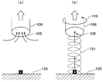
- FIG. 20 shows a flow through a conventional suction port.
- a potential flow generated by a normal stationary suction port 105 is generated as indicated by an arrow.
- the fluid air forms a potential flow and is uniformly sucked into the suction port 105 at a speed inversely proportional to the distance from the suction port 105. Therefore, the suction flow is dispersed without directivity, and the suction airflow does not reach the floor surface 125.
- the air is sucked into the suction port 105 while forming the artificial tornado 131.
- the suction port 105 and the suction port duct 106 rotate in the rotation direction 119.
- an air vortex indicated by an arrow that is, an artificial tornado 131 is generated. Since the artificial tornado 131 reduces the dispersion of the suction flow and causes the directivity of the suction flow, the suction airflow reaches the floor surface 125.
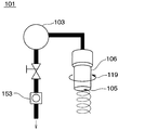
- FIG. 21 shows an example of the suction device 101 that generates the artificial tornado 131 as shown in the example (b) of FIG.
- the suction device 101 generates an artificial tornado 131 by rotating a cylindrical suction port duct 106 having a suction port 105.
- the sucked air is exhausted out of the suction device 101 through the suction pump 103 and the flow meter 153.
- the artificial tornado 131 is generated by the rotation of the cylindrical suction duct 106.
- the rotational force of the artificial tornado 131 is weak and unstable because the force for rotating the air by the inner wall of the suction duct 106 is weak. Therefore, it is difficult to continuously generate the artificial tornado 131.
- Patent Documents 1 to 5 show devices for generating and sucking artificial tornado 131.
- Patent Document 1 discloses a ventilator that generates an artificial tornado 131 by rotating together with a cylindrical duct fan having the same large diameter as the fan larger than the diameter of the suction port at the suction port.
- this ventilator since the total length of the cylindrical duct is required to be twice or more the thickness of the fan, the size of the ventilator becomes large.
- Patent Document 2 discloses an intake nozzle in which a conical duct is attached to a suction port, and an intake port is provided around the large-diameter side of the duct so as to generate a swirling flow.
- the intake nozzle is large in size and requires a blower that supplies a jet to the intake port.
- Patent Documents 1 and 2 generate an artificial tornado with a structure of suction only, but require a large-diameter cylindrical duct that rotates or a conical duct and a blower that supplies a jet.
- Patent Document 3 a large hood that collects the suction flow around the suction port is attached, a zone is formed with an air curtain on the downstream side of the hood, and swirling from the air discharge ports of the four pipes that constitute the air curtain inside the zone An exhaust device is shown in which air is discharged so as to form a flow, and an artificial tornado 131 is generated and sucked into a suction port.
- the exhaust device requires a large hood, an air curtain pipe, and a blower for generating a dedicated jet for the air curtain.
- Patent Document 4 a large hood is attached around the suction port, outside air is discharged inside the hood in the circumferential direction to generate a swirling flow, and is discharged to the floor as a primary tornado upstream.
- a ventilation device is shown in which a secondary tornado is generated as a reflected flow of the surface and sucked into a suction port.
- the exhaust device requires a large hood, a blower dedicated to a jet that generates a primary tornado, and a floor surface that generates a secondary tornado (artificial tornado 131).
- Patent Document 5 a suction port is provided on one side, a discharge port is provided on the other side, a cylindrical duct is provided upstream of the discharge port, a jet swirl is generated along the circumference, and an artificial tornado is generated from the discharge port.
- a baking cooking apparatus having a ventilation device for sucking into a suction port is shown. This baking cooking apparatus requires a discharge device on the other side of the suction port.
- Patent Documents 3 to 5 require not only a suction side but also a device that blows a floor surface or a jet on the other side, and requires large-scale equipment.
- An object of the present invention is to provide a suction device that can stably generate an artificial tornado on the suction side.
- the suction device includes a suction port that revolves around the revolution axis while sucking a fluid.
- the artificial tornado can be generated more stably than in the past because the suction port revolves around the revolution axis while sucking the fluid.
- a revolution zone is formed in an inner region of the shape drawn by the outermost peripheral portion of the suction port.
- the circumferential velocity vector V ⁇ of the revolving zone is generated by dragging air in the circumferential direction to the suction port.
- the circumferential velocity vector V ⁇ provides a suction device that generates a strong and stable artificial tornado.
- An artificial tornado can be generated only by a mechanism that revolves the suction port of the suction device.
- the radial velocity vector Vr can be further strengthened by having a negative pressure region inside the revolution zone. Therefore, a powerful and stable artificial tornado can be generated by the combined velocity vector Vt of the circumferential velocity vector V ⁇ and the radial velocity vector Vr.
- the suction speed of the revolution zone has a speed gradient that decreases from the inside of the revolution shaft side to the outer peripheral portion. As a result, a radial velocity vector Vr acting in the radial direction of the circle centered on the revolution center 10 is generated.
- the suction device includes a driving device that revolves the suction port around the revolution axis when the suction port is sucking the fluid.
- a driving device that revolves the suction port around the revolution axis when the suction port is sucking the fluid.
- the suction device includes a suction port duct including the suction port, a connection duct connected to the suction port duct, and a suction duct connected to the connection duct.
- the suction duct extends around the revolution shaft so that the revolution shaft is located inside.
- the connection duct extends from the opening on the suction duct side to the opening on the suction port duct side so as to be away from the revolution axis.
- the suction port duct is located at a position away from the revolution axis.
- the suction device includes a rotating plate in which the suction port is opened, a suction port duct connected to the rotating plate, and a suction duct connected to the suction port duct. . Further, the suction port is opened at a position away from the revolution shaft in the rotating plate. In addition, when the rotating plate rotates about the revolution axis, the suction port revolves around the revolution axis. With such a simple configuration, an artificial tornado can be generated more stably than in the past.
- the suction port rotates.
- the suction port By rotating the suction port, the artificial tornado can be further strengthened and stabilized. This is because the frictional force generated on the inner wall of the suction port duct can be used.
- the driving device revolves the suction port around the revolution axis when the suction port is sucking fluid.
- the driving device operates so that the suction port revolves around the revolution axis while sucking the fluid, so that the artificial tornado can be generated more stably than in the past.
- Example 1 shows a suction device according to a first embodiment. It is a front view of the suction device which concerns on 2nd Embodiment. It is a side view of the suction device which concerns on 2nd Embodiment.
- a schematic diagram of the experimental state is shown. An experimental apparatus is shown. Experimental conditions of Example 1 and Example 2 are shown. The result of Example 1 is shown (dry ice mist). The result of Example 1 is shown (dry ice mist). The result of Example 1 is shown (tuft). The result of Example 1 is shown (tuft). It is a figure which shows velocity distribution of potential flow. It is a figure which shows speed distribution at the time of revolving a suction port. It is a figure which shows distribution in a horizontal surface of vorticity.
- Example 2 shows distribution in the horizontal surface of circumferential speed. It is a figure which shows distribution in the horizontal surface of circumferential speed. It is a graph which shows radial direction distribution of circumferential speed. It is a graph which shows the relationship between the maximum value of circumferential speed and the rotation speed of revolution. Shows the mechanism of artificial tornadoes (revolution radius ⁇ suction port radius). The mechanism by which an artificial tornado occurs (revolution radius> suction port radius) is shown.
- the result of Example 2 is shown (dry ice mist). The result of Example 2 is shown (dry ice mist).
- the experimental conditions of Example 3 are shown. The result of Example 3 is shown (dry ice mist). The result of Example 3 is shown (dry ice mist).
- Example 3 The result of Example 3 is shown (tuft).
- the result of Example 3 is shown (tuft). It is a figure which shows the air conditioning apparatus which concerns on 3rd Embodiment. The flow of the conventional suction port is shown. The example of the suction device which generates the conventional artificial tornado is shown.
- FIG. 1 shows a first embodiment of the present invention.
- the revolution of the suction port 5 is realized by the rotation around the revolution axis 11 of the suction duct 8.
- the suction device 1 of the present embodiment has a suction port duct 6, a connection duct 7, a suction duct 8, a suction pump 3, a discharge duct 9, and a drive device (not shown).
- the suction port duct 6 has a suction port 5 at an end portion far from the connection duct 7.
- the suction port duct 6, the connecting duct 7, and the suction duct 8 rotate integrally.
- the revolution center 10 is on the revolution axis 11.
- the suction port 5 is circular, and the center point of the circle is a revolution point 13.
- the distance between the revolution point 13 and the revolution center 10 is a revolution radius R.
- the revolution zone 15 is an area inside the shape (that is, the arc) drawn by the outermost peripheral portion of the suction port 5 when the suction port 5 revolves around the revolution center 10.
- the outermost peripheral portion refers to the outermost circumference in the radial direction around the revolution shaft 11.
- the inside of the suction port inner locus 16 drawn by the innermost part of the suction port 5 when the suction port 5 revolves around the revolution center 10 is also included in the revolution zone 15.
- the innermost part means the innermost part in the radial direction around the revolution axis 11.
- the opening on the side near the connecting duct 7 of the suction port duct 6 having the suction port 5 is connected to one opening of the connecting duct 7.
- the other opening of the connecting duct 7 is connected to one opening of the suction duct 8.
- the other opening of the suction duct 8 is connected to the suction port of the suction pump 3.
- One opening of the discharge duct 9 is connected to the discharge port of the suction pump 3.
- the other opening of the discharge duct 9 is open.
- the suction duct 8 surrounds the revolution shaft 11 and extends along the revolution shaft 11 so that the revolution shaft 11 is located inside the suction duct 8.
- the connecting duct 7 extends from the opening on the suction duct 8 side to the opening on the suction port duct 6 side so as to move away from the revolution shaft 11.
- the suction port duct 6 extends parallel to the revolution shaft 11 at a position away from the revolution shaft 11.
- connection duct 7 and the suction port duct 6 revolve around the revolution shaft 11.
- suction port 5 revolves around the revolution center 10 as described above.
- the revolution trajectory of the revolution point 13 is a circle centered on the revolution center 10.
- the revolution shaft 11 coincides with the center line of the suction duct 8 of the suction device 1. Therefore, when a driving device (not shown) rotates the suction duct 8 around the center line of the suction duct 8, the suction port 5 revolves around the revolution axis 11 with the revolution radius R.
- the air around the artificial tornado 31 is hardly sucked into the artificial tornado 31 and flows to the suction device 1 side as an accompanying flow 33 having a low speed.
- FIG. 2A and 2B show a second embodiment of the present invention.
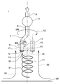
- FIG. 2A is a front view of the suction device 1 in the present embodiment
- FIG. 2B of the suction device 1 in the present embodiment is a side view.
- the revolution of the suction port 5 is realized by the rotation around the revolution center 10 of the rotating plate 4.
- the revolution center 10 is on the revolution axis 11 as in the first embodiment.
- the rotating plate 4 has a disk shape, but may have other shapes.
- the rotating plate 4 is rotated around the revolution shaft 11 by a driving device (not shown) such as a motor.
- a driving device such as a motor.
- the suction port duct 6 and the suction duct 8 may rotate together with the rotating plate 4 or may not rotate.
- a hole opened in the rotating plate 4 is a suction port 5.
- the rotating plate 4 is connected to one opening of the suction port duct 6.
- the other opening of the suction port duct 6 is connected to one side of the suction duct 8.
- the center line of the suction port duct 6 and the suction duct 8 is common and is the revolution axis 11, and the center of the rotating plate 4 is on the revolution axis 11 and becomes the revolution center 10.
- the other opening of the suction duct 8 is connected to the suction port 5 of the suction pump 3.
- One opening of the discharge duct 9 is connected to the discharge port of the suction pump 3.
- the other opening of the discharge duct 9 is open.
- the diameter of the suction port duct 6 is larger than the diameter of the suction duct 8, but the suction port duct 6 is tapered from the opening on the one rotating plate 4 side toward the opening on the other suction duct 8 side.
- the air resistance in the interior may be reduced.
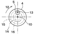
- the suction port 5 provided in the rotating plate 4 is opened at a position away from the revolution shaft 11 in the rotating plate 4. Therefore, when the rotating plate 4 rotates, it revolves around the revolution center 10 in the revolution direction 12.
- the revolution speed N of the suction port 5 is substantially the same as the vortex speed of the artificial tornado 31.
- the suction port 5 has a circular shape, and the center point of the circle is a revolution point 13.
- the distance between the revolution point 13 and the revolution axis 11 is the revolution radius R.
- the revolution point 13 draws a circular revolution locus 14 having a revolution radius R.
- the revolution zone 15 is an arc region drawn by the outermost periphery of the suction port 5 when the suction port 5 revolves around the revolution center 10.
- the inside of the suction port inner locus 16 drawn by the innermost part of the suction port 5 when the suction port 5 revolves around the revolution center 10 is also included in the revolution zone 15.
- the suction port duct 6 and the suction duct 8 extend so as to surround the revolution shaft 11 so that the revolution shaft 11 is positioned inside.
- the suction port 5 is opened at a position away from the revolution shaft 11 in the rotating plate 4. When the rotating plate 4 rotates about the revolution shaft 11, the suction port 5 revolves around the revolution shaft 11.
- the suction port inner locus 16 exists when the revolution radius R is larger than the suction port radius, and does not exist when the revolution radius R is smaller than the suction port radius.
- the revolution point 13 of the suction port 5 revolves around the revolution axis 11 with a revolution radius R.
- the shape of the suction port 5 is not limited to a circle but may be an ellipse or a square.
- the revolution point 13 may not be the center of the suction port 5 as long as it can regulate the revolution of the suction port 5.
- the revolving trajectory of the revolution point 13 is indicated by a revolution trajectory 14.
- the revolution direction 12 may be opposite to the direction shown in FIGS. 1 and 2A. In this case, the vortex flow of the artificial tornado 31 is also in the reverse direction.
- FIG. 3 shows a schematic diagram of an experimental environment in which the suction device 1 according to the first embodiment shown in FIG. 1 is installed vertically on the floor surface 25.
- the revolution direction 12 of the suction port 5 and the rotation direction 19 of the suction port duct 6 are the same rotation direction.
- the suction duct 6 is rotated in the rotation direction 19, the artificial tornado 31 is rotated in the rotation direction 35 due to the rotation.
- the rotation of the suction port duct 6 refers to the rotation of the suction port duct 6 with respect to a coordinate system that rotates around the revolution axis 11 together with the suction port 5.
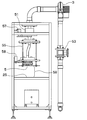
- FIG. 4 shows an experimental apparatus embodying the schematic diagram of the experimental state shown in FIG.
- a flow meter 53 for measuring the air volume is installed on the discharge side of the suction pump 3.
- the observation area 59 is between the suction port 5 and the floor surface 25.
- the height of the observation area 59 is 200 mm.
- the driven portion 55 corresponds to the suction port duct 6, the connection duct 7, and the suction duct 8 shown in FIG. 3.
- the first motor 57 is a drive device that revolves the suction port 5 by rotating the driven part 55.
- a second motor 58 that rotates the suction port 5 is mounted below the driven portion 55.
- the second motor 58 moves with the driven part 55.
- a slip ring 51 having a brush function is mounted on the driven portion 55. Visual observation of the artificial tornado 31 in the observation area 59 was performed using dry ice mist and tuft.
- Example 1 In Example 1, generation
- FIG. 5 shows the experimental conditions of Example 1 and Example 2.
- the air volume Q is 60 m 3 / h.
- the inner diameter of the suction port 5 is 32 mm. The same applies to the third embodiment.
- Cases 1-1, 1-2, and 1-3 show experimental conditions of an example in which the suction port 5 only rotates. This is the condition of the example of only the rotation of the conventional suction port 105 and the suction port duct 106 shown in the example (b) of FIG.
- the revolution speed N in FIG. 5 actually corresponds to the rotation speed n of the suction port 5, not the revolution speed of the suction port 5. Therefore, the rotation speed n is set to 120 rpm, 150 rpm, and 180 rpm, respectively.
- Cases 1-4 to 1-12 The experimental conditions for revolution only are shown in Cases 1-4 to 1-12.
- the revolution radius R was set to 10 mm.
- Cases 1-7, 1-8, and 1-9 have a revolution radius R of 20 mm.
- Cases 1-10, 1-11, and 1-12 had a revolution radius R of 30 mm.
- the revolution speed N was 120 rpm, 150 rpm, and 180 rpm, respectively. Observation of the state of occurrence of the artificial tornado 31 was performed for 3 minutes each.
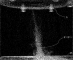
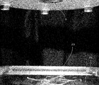
- FIG. 6A and 6B show the results of Example 1.
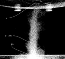
- the artificial tornado 31 continued without interruption for 3 minutes during observation, and the thickness of the vortex tube was almost constant.
- the thickness of the vortex tube became thinner as it approached the suction port 5.
- the artificial tornado 31 was observed to be strong and fairly stable in the case of revolution alone, compared with the case of rotation alone.
- FIGS. 7A and 7B show the results of Example 1.
- the other conditions are the same in FIGS. 7A and 6A, and the same in FIGS. 7B and 6B.
- a tuft 23 was attached in the vicinity of the intersection with the revolution axis 11 on the floor surface 25, and the suction force on the floor surface 25 of the artificial tornado 31 was observed.
- the artificial tornado 31 confirmed that the tuft 23 was lifted vertically without interruption for 3 minutes during observation. Therefore, it was confirmed that remote suction is possible.
- the artificial tornado 31 observed that the tuft 23 could not be lifted in the vertical direction only by the rotation of FIG. 7B. Therefore, it was confirmed that remote suction is difficult.
- FIG. 8 shows the air flow velocity distribution in the upward direction when suction is performed in the experimental environment of FIG. 4 without revolution or rotation.
- the black portion has a flow velocity of 5 m / s or more
- the white portion has a flow velocity of less than 5 m / s.
- This flow velocity distribution was measured by a well-known PIV (Particle Image Velocity).
- the vertical axis corresponds to the vertical position with the position of the suction port 5 as the zero point
- the horizontal axis corresponds to the horizontal position.
- the upward flow velocity of 5 m / s is realized in a semicircular region centered on the revolution center 10 of the suction port 5.
- the velocity of air is approximately 0 m / s at a position away from the suction port 5 by 30 mm or more.
- FIG. 9 shows the speed distribution when the suction port 5 is revolved by PIV.
- the black portion has a flow velocity of 5 m / s or more, and the white portion has a flow velocity of less than 5 m / s.
- the upper part of FIG. 9 shows the air flow velocity distribution in the upward direction at various revolution speeds where only the revolution is realized with the revolution radius R being 8 mm (that is, 0.25 times the inner diameter ⁇ 32 mm of the suction port 5).
- the revolution radius R was set to 12 mm (that is, 0.375 times the inner diameter ⁇ 32 mm of the suction port 5), and only the revolution was realized (revolution speed 120, 150, 180, 210 rpm from the left).
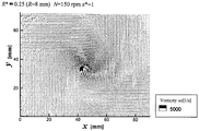
- FIG. 10 shows that the revolution radius R is 8 mm (that is, 0.25 times the inner diameter ⁇ 32 mm of the suction port 5), the revolution speed is 150 rpm, and the vorticity wz of the air in the horizontal plane is a predetermined time width in the experiment of revolution only. It is a figure which shows the average value over.
- the vertical distance from the horizontal suction port is 32 mm, which is the same as the inner diameter of the suction port 5.
- the center position in this figure is adjusted so that it is always located at the center position of the air vortex tube in the predetermined time width. That is, the center position in this figure is the origin of the coordinate system that moves together with the center position of the air vortex tube.
- the vorticity wz is 5000 (1 / s) or more for the black portion and less than 5000 (1 / s) for the white portion. Therefore, a large vorticity is generated at the center of the air vortex tube.
- the arrow described in the white part is the circumferential speed V ⁇ of the air in the horizontal plane.
- FIG. 11A shows the average value over the predetermined time width of the circumferential velocity V ⁇ of the air in the horizontal plane in the experiment in which the revolution radius R is 8 mm, the revolution speed is 150 rpm, and the revolution only.
- the distance from the suction port on the horizontal plane is 128 mm, which is four times the inner diameter of the suction port 5.
- the center position in this figure is adjusted so that it is always located at the center position of the air vortex tube in the predetermined time width.
- the circumferential direction is a circumferential direction centered on the center position of the vortex tube.
- the circumferential speed V ⁇ is 3 m / s or more for the black portion and less than 3 m / s for the white portion.
- the central portion of the air vortex tube has a donut shape in the range where the circumferential velocity V ⁇ is 3 m / s or more, the circumferential velocity V ⁇ is small at the center of the donut, and the upward air flow shown in FIG. 9 is large. It has become.
- FIG. 11B shows an average value over a predetermined time width of the circumferential velocity V ⁇ of the air in the horizontal plane in the experiment in which the revolution radius R is 8 mm, the revolution speed is 120 rpm, and the revolution only.
- the distance from the suction port on the horizontal plane is 128 mm, which is four times the inner diameter of the suction port 5.
- the center position in this figure is adjusted so that it is always located at the center position of the air vortex tube in the predetermined time width.
- the circumferential speed V ⁇ is 3 m / s or more for the black portion and less than 3 m / s for the white portion.
- the central portion of the air vortex tube has a donut shape in the range where the circumferential velocity V ⁇ is 3 m / s or more, the circumferential velocity V ⁇ is small at the center of the donut, and the upward air flow shown in FIG. 9 is large. It has become.
- FIG. 12A shows a radial distribution of an average value over a predetermined time width of the circumferential velocity V ⁇ of air.
- the results shown in FIG. 12A are the results obtained for seven types of revolution speeds N when the revolution radius R is 8 mm.
- the radial direction here is a radial direction centered on the center of the vortex tube at each time point.
- the distance from the suction port on the horizontal plane is 128 mm, which is four times the inner diameter of the suction port 5.
- the center position in this figure is adjusted so that it is always located at the center position of the air vortex tube in the predetermined time width.
- the circumferential velocity V ⁇ of the air vortex has a maximum value.
- the inner side of the maximum value in the radial direction behaves as a rigid vortex that decreases rapidly and has a central portion of approximately 0 m / s.
- the outside of the maximum value in the radial direction behaves as a free vortex that decreases gradually. That is, this vortex has a circumferential velocity distribution equivalent to that of a general Rankine vortex type tornado.
- a horizontal line is drawn at a circumferential speed V ⁇ of 3000 mm / s (3 m / s) on the vertical axis, and the upper part of the graph is painted black and the lower part is displayed in white. Is shown in FIG. 11A.
- the artificial tornado 31 has an air flow having a large velocity toward the suction port 5, a circumferential speed V ⁇ having a maximum value, and a large suction port inside the maximum value. It has an air flow toward 5.
- FIG. 12B is a graph showing the maximum value in the radial distribution of the circumferential velocity V ⁇ at each revolution speed N in the result shown in FIG. 12A.
- the horizontal axis corresponds to the revolution speed N, and the vertical axis corresponds to the local maximum value in the radial distribution of the circumferential speed V ⁇ .
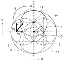
- FIG. 13 is a conceptual diagram showing the mechanism of the generation of an artificial tornado at the revolution radius R ⁇ the suction port radius.
- the suction port 5 revolves around the revolution center 10 in the revolution direction 12.
- the rotational position where the suction port 5 is rotated three times by 90 ° is indicated by three broken lines.
- a center point of the suction port 5 that is circular is indicated by a revolution point 13.
- a trajectory of the revolution point 13 having the revolution radius R is indicated by a revolution trajectory 14.
- the suction range covered by the revolution of the suction port 5 is defined as a revolution zone 15.
- the circumferential velocity vector V ⁇ and the circumferential velocity V ⁇ are represented by the same symbol, but the former is a three-dimensional vector quantity and the latter is a scalar quantity.
- the magnitude of the circumferential speed vector V ⁇ corresponds to the circumferential speed V ⁇ .
- the circumferential velocity vector V ⁇ is generated when the continuous fluid air is dragged in the circumferential direction by the revolution of the suction port 5, and acts in the circumferential direction of the circle centered on the revolution center 10. Note that the artificial tornado 31 is generated only by the circumferential velocity vector V ⁇ .
- the radial velocity vector Vr is generated when a velocity gradient is generated in the suction air volume in the revolution zone 15 due to the revolution of the suction port 5, and acts in the radial direction of a circle centered on the revolution center 10.
- the speed gradient of the suction speed in the revolution zone 15 increases as the periphery of the revolution center 10 increases and decreases toward the outside. This is because the suction port 5 always sucks around the revolution shaft 11 but intermittently sucks outside due to revolution. Therefore, the radial velocity vector Vr acts in the radial direction of the circle centered on the revolution center 10.
- the artificial tornado 31 is generated more powerfully and stably by the combined velocity vector Vt of the circumferential velocity vector V ⁇ and the radial velocity vector Vr.
- the combined velocity vector Vt is in the direction of the vortex of the artificial tornado 31.
- FIG. 14 is a conceptual diagram showing the mechanism of the generation of an artificial tornado when the revolution radius R> the suction port radius.
- the suction port 5 revolves around the revolution axis 11 in the revolution direction 12. The positions where the suction port 5 has been rotated three times by 90 ° are indicated by three broken lines.
- a center point of the suction port 5 that is circular is indicated by a revolution point 13.
- a trajectory of the revolution point 13 having the revolution radius R is indicated by a revolution trajectory 14.
- the suction range covered by the revolution of the suction port 5 is defined as a revolution zone 15. In the vicinity of the revolution center 10, there is a suction port inner locus 16 that is an inner locus of the suction port 5.
- the circumferential velocity vector V ⁇ is generated when the continuous fluid air is dragged in the circumferential direction by the revolution of the suction port 5, and acts in the circumferential direction of the circle centered on the revolution center 10. Note that the artificial tornado 31 is generated only by the circumferential velocity vector V ⁇ .
- the radial velocity vector Vr is generated when a velocity gradient is generated in the suction air volume in the revolution zone 15 due to the revolution of the suction port 5, and acts in the radial direction of a circle centered on the revolution center 10.
- the speed gradient of the suction speed in the revolution zone 15 increases near the outside of the suction port inner locus 16 and decreases as it moves outward.
- the suction port 5 is intermittently sucked by revolution, but the suction interval time near the outside of the suction port inner locus 16 is short, while the suction interval time is long outside the revolution zone 15 part. Therefore, the radial velocity vector Vr acts in the radial direction of the circle centered on the revolution axis 11.
- the inside of the suction port inner locus 16 has a negative pressure compared to the atmospheric pressure (static pressure). That is, the inside of the suction port inner locus 16 is in a state equivalent to the suction from the closed space, and the static pressure becomes a negative pressure.
- the inside of the suction port inner locus 16 becomes equivalent to the closed space because the suction port 5 sucks air simultaneously with high-speed rotation of about 120 rpm (twice / second). This is because the suction of the air is a suction state from the release space, while the suction from the inside of the suction port inner locus 16 is the suction from the limited space. Therefore, due to this negative pressure, the radial velocity vector Vr acting in the radial direction of the circle centered on the revolution center 10 increases.
- the negative pressure level at that position is referred to as the negative pressure level at that position.
- the negative pressure level at the radial center portion is higher than the negative pressure level at the radial outer peripheral portion that is radially outside the radial center portion around the revolution center 10. More specifically, the negative pressure level in the revolution zone 15 decreases as the distance from the revolution center 10 increases.
- a powerful artificial tornado 31 is generated by the combined velocity vector Vt of the circumferential velocity vector V ⁇ and the radial velocity vector Vr.
- the combined velocity vector Vt is in the direction of the vortex of the artificial tornado 31.
- the artificial tornado 31 When the artificial tornado 31 is generated in the revolution zone 15 by the mechanism described above, the artificial tornado 31 develops toward the upstream side of the suction port 5 of the revolution shaft 11. Since air is a continuous fluid, the revolution speed N of the suction port 5 is almost the same as the vortex speed of the artificial tornado 31.
- the artificial tornado 31 mainly sucks air from its tip and does not suck much from its side.
- the accompanying flow 33 gently flows toward the outside of the revolution zone 15 of the suction device 1.
- the suction device 1 can perform directional suction.
- This directional suction makes it possible to perform remote suction that efficiently sucks gas or suspended matter existing in a specific space in the free space of the atmosphere.
- the artificial tornado 31 generated as described above is composed of an upward flow, a circumferential flow, and an inward flow due to negative pressure. Then, the configuration of the revolution zone 15 induces a circumferential flow and an inward flow in the artificial tornado 31. The upward flow occurs even without the revolution zone 15 (that is, even when the suction port 5 does not revolve).
- the static pressure inside the suction port inner locus 16 becomes a negative pressure lower than the atmospheric pressure (static pressure).
- the artificial tornado 31 outside the suction port inner locus 16 is pulled inside the suction port inner locus 16.
- the artificial tornado 31 can be stably maintained for a longer time than before.
- the static pressure in the vicinity of the revolution shaft 11 (specifically, the inside of the revolution locus 14) becomes a negative pressure lower than the atmospheric pressure.
- the artificial tornado 31 outside the suction port inner locus 16 is pulled to the negative pressure region.
- the artificial tornado 31 can be stably maintained for a longer time than before.
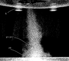
- Example 2 In Example 2, the state of occurrence of the artificial tornado 31 with the revolution radius R was observed. 15A and 15B show the results of Example 2. FIG. In this experimental result, dry ice mist is used to visualize the air flow.
- Example 3 In Example 3, the artificial tornado 31 was observed by simultaneously applying the rotation of the suction port 5 to the revolution of the suction port 5. Note that the rotation direction is the same as the revolution direction 12. This is because the artificial tornado 31 generated by the revolution of the suction port 5 is reinforced by the rotation of the suction port duct 6.
- FIG. 16 shows the experimental conditions of Example 3.
- the artificial tornado 31 was observed under 36 conditions from Case 2-1 to 2-36.
- FIG. 17A and FIG. 17B show the results of Example 3.
- dry ice mist is used to visualize the air flow.
- the artificial tornado 31 was further stabilized when rotation was applied, compared to the case of revolution alone.
- FIGS. 17A and 17B show the results of Example 3.
- Rotating the suction duct 6 in the rotation direction 19 causes the artificial tornado 31 to rotate in the rotation direction 35 as shown in FIG. As a result, the artificial tornado 31 becomes more powerful.
- the shape of the revolution locus of the revolution locus 14 may be not only a circle but also an ellipse, a rectangle, or a hexagon.
- the shape of the suction port 5 may be not only a circle but also an ellipse, a quadrangle, or a hexagon.
- the strength of the artificial tornado can be adjusted by the size (radius, etc.) of the suction port 5, the suction flow rate, the revolution radius R, and the revolution speed N.
- the experimental device of FIG. 4 can rotate the suction port 5, but the action of the artificial tornado 31 of the suction device 1 of the present invention is caused by the revolution of the suction port 5.
- the air conditioner 60 of this embodiment is fixed to the indoor ceiling or side wall.
- the air conditioner 60 heats the air in order to heat the room, and blows out the heated air 61 in an obliquely downward vertical direction in the room.
- cold air 64 tends to stay in the lower part of the room and warm air tends to stay in the upper part of the room.
- Such a temperature distribution leads to deterioration in heating efficiency because the living space below the room does not warm.
- the air conditioner 60 of this embodiment has the suction device 1 which concerns on 1st Embodiment or 2nd Embodiment, as shown in FIG.
- the suction port 5 of the suction device 1 is open vertically downward or vertically downward in the room.
- the operation mode of the suction device 1 is the same as in the first and second embodiments.
- the suction port 5 When the suction port 5 is sucking air, the suction port 5 revolves around the revolution shaft 11, thereby generating an artificial tornado 63.
- the artificial tornado 63 When the artificial tornado 63 is generated, cool air below the room is sucked into the suction port 5. Thereby, the air (warm air) blown out from the air conditioner 60 moves downward in the room as indicated by an arrow 62.
- warm air reaches the lower end of the room as indicated by an arrow 62, the temperature below the room rises, the temperature difference between the upper and lower sides is reduced, and the heating efficiency is improved.
- the present invention has the following operations and effects.
- the suction device 1 having the suction port 5 for sucking the fluid has the revolution zone 15 by revolving the suction port 5 around the revolution shaft 11.
- the circumferential velocity vector V ⁇ of the revolving zone 15 is generated when air is dragged to the suction port 5 in the circumferential direction.
- the circumferential velocity vector V ⁇ generates a strong and stable artificial tornado 31.
- the suction device 1 Since the artificial tornado 31 can be generated only by a mechanism for revolving the suction port 5 of the suction device 1, the suction device 1 can be made small. Therefore, the large-sized duct, the hood, and the jet blower for generating the swirling flow, which are necessary in the prior art, can be eliminated.
- the suction device 1 of the above-described embodiment may be used in combination with a duct, a hood, and a jet blower that generates a swirling flow.
- the suction speed of the revolution zone 15 has a speed gradient that decreases from the inside of the revolution shaft side to the outer peripheral portion.
- a radial velocity vector Vr that acts in the radial direction of a circle centered on the revolution center 10 is generated.
- the suction device 1 is connected to a suction port duct having a suction port 5 and has a suction duct that rotates around a revolution axis.
- a suction port duct having a suction port 5 By connecting to the suction port duct 6 having the suction port and having the suction duct 8 rotating around the revolution axis 11, the rotation of the suction port 5 can be performed only by the rotation of the suction duct 8.
- the mechanism for revolving the suction port 5 can be directly connected to the rotation of the motor, so that it can be simplified.
- the suction port 5 rotates around the revolution point.
- the artificial tornado can be made more powerful and stable. This is because the frictional force generated on the inner wall of the suction port duct 6 can be used.
- the suction device 1 of the present invention can be used for a dust collector, a ventilation device, an exhaust device, a low pressure generator, and the like.
- vacuum cleaners, machine tool chip removal devices, blast furnace dust collectors, smoke separators, barbecue smoke exhaustors, liquid level control devices, etc., and artificial tornado 31 directs suction. It is possible to efficiently collect dust, ventilate, exhaust, etc. Further, dust or the like scattered in a specific area in the air can be collected by focusing on the specific area with the artificial tornado 31. The artificial tornado 31 can also capture harmful mosquitoes in flight.
- the fluid sucked into the suction device 1 may be not only air but also other gases such as hydrogen, oxygen, and nitrogen. Moreover, liquid (water, alcohol, etc.) may be sufficient.
Landscapes
- Engineering & Computer Science (AREA)
- Mechanical Engineering (AREA)
- General Engineering & Computer Science (AREA)
- Chemical & Material Sciences (AREA)
- Combustion & Propulsion (AREA)
- Ventilation (AREA)
- Wind Motors (AREA)
- Jet Pumps And Other Pumps (AREA)
Abstract
Un dispositif d'aspiration (1) génère un tourbillon artificiel (31) au moyen d'un orifice d'aspiration (5) qui tourne autour d'un axe de révolution (11) tout en aspirant un fluide.
Priority Applications (4)
| Application Number | Priority Date | Filing Date | Title |
|---|---|---|---|
| CN201780051469.XA CN109716037A (zh) | 2016-06-22 | 2017-06-21 | 吸引装置和驱动装置 |
| JP2018524136A JP6694633B2 (ja) | 2016-06-22 | 2017-06-21 | 吸引装置および駆動装置 |
| EP17815444.9A EP3477213A4 (fr) | 2016-06-22 | 2017-06-21 | Dispositif d'aspiration et dispositif de commande |
| US16/226,732 US10792676B2 (en) | 2016-06-22 | 2018-12-20 | Suction device and drive device |
Applications Claiming Priority (2)
| Application Number | Priority Date | Filing Date | Title |
|---|---|---|---|
| JP2016-123282 | 2016-06-22 | ||
| JP2016123282 | 2016-06-22 |
Related Child Applications (1)
| Application Number | Title | Priority Date | Filing Date |
|---|---|---|---|
| US16/226,732 Continuation US10792676B2 (en) | 2016-06-22 | 2018-12-20 | Suction device and drive device |
Publications (1)
| Publication Number | Publication Date |
|---|---|
| WO2017221976A1 true WO2017221976A1 (fr) | 2017-12-28 |
Family
ID=60784656
Family Applications (1)
| Application Number | Title | Priority Date | Filing Date |
|---|---|---|---|
| PCT/JP2017/022850 Ceased WO2017221976A1 (fr) | 2016-06-22 | 2017-06-21 | Dispositif d'aspiration et dispositif de commande |
Country Status (5)
| Country | Link |
|---|---|
| US (1) | US10792676B2 (fr) |
| EP (1) | EP3477213A4 (fr) |
| JP (1) | JP6694633B2 (fr) |
| CN (1) | CN109716037A (fr) |
| WO (1) | WO2017221976A1 (fr) |
Cited By (1)
| Publication number | Priority date | Publication date | Assignee | Title |
|---|---|---|---|---|
| JP2022163842A (ja) * | 2021-04-15 | 2022-10-27 | 作一 君島 | テーブル用エアカーテン |
Families Citing this family (1)
| Publication number | Priority date | Publication date | Assignee | Title |
|---|---|---|---|---|
| CN112676209A (zh) * | 2020-12-29 | 2021-04-20 | 广东安达智能装备股份有限公司 | 一种小型校准清洗预热飞达系统 |
Citations (10)
| Publication number | Priority date | Publication date | Assignee | Title |
|---|---|---|---|---|
| JPS50156067A (fr) * | 1974-06-06 | 1975-12-16 | ||
| JPH05296511A (ja) | 1992-04-22 | 1993-11-09 | Kumagai Gumi Co Ltd | 竜巻を利用した換気装置 |
| JPH06313599A (ja) * | 1993-04-30 | 1994-11-08 | Shin Nippon Kucho Kk | 換気ユニット |
| JPH0742996A (ja) * | 1993-07-30 | 1995-02-10 | Takasago Thermal Eng Co Ltd | 排気装置 |
| JPH08285340A (ja) | 1990-12-10 | 1996-11-01 | Torunetsukusu:Kk | 人工竜巻式局所排気装置 |
| JP2000234773A (ja) | 1999-02-15 | 2000-08-29 | Daikin Ind Ltd | 換気装置 |
| JP2008256292A (ja) | 2007-04-06 | 2008-10-23 | Nishiki:Kk | 焼成調理装置 |
| JP2008264682A (ja) * | 2007-04-20 | 2008-11-06 | Kemikaru Koji:Kk | 樹脂散布装置及びその制御方法 |
| JP2014181888A (ja) | 2013-03-21 | 2014-09-29 | Dainippon Printing Co Ltd | 排気ノズル |
| JP2016109112A (ja) * | 2014-12-08 | 2016-06-20 | トルネード システムズ カンパニー,リミテッド | スワラーファンを備えた排気装置モジュール |
Family Cites Families (14)
| Publication number | Priority date | Publication date | Assignee | Title |
|---|---|---|---|---|
| US4692959A (en) * | 1986-03-11 | 1987-09-15 | Monson Clifford L | Rotary cleaner/scrubber mechanism |
| JPS62261842A (ja) * | 1986-05-09 | 1987-11-14 | Nippon Air Curtain Kk | 人工竜巻発生機構とその利用法 |
| KR100268044B1 (ko) * | 1995-09-15 | 2000-11-01 | 마 쯔이 시게오 | 인공회오리발생기구와 그이용장치 |
| US6036871A (en) * | 1996-04-25 | 2000-03-14 | Fan Separator Gmbh | Method and device for separating heavier from lighter parts of aqueous slurries by means of centrifugal force effects |
| JP2002162076A (ja) * | 2000-11-24 | 2002-06-07 | Tornex Inc | 竜巻発生方法及びその装置 |
| JP2002206781A (ja) * | 2000-12-30 | 2002-07-26 | Tornex Inc | 包囲体利用の吸引装置 |
| US6643894B1 (en) * | 2002-02-28 | 2003-11-11 | William C. Dell | High efficiency vacuum cleaning apparatus and method |
| KR100529002B1 (ko) * | 2003-12-31 | 2005-11-15 | 학교법인 포항공과대학교 | 덮개가 구비된 스월러를 이용하는 국소배기장치 |
| JP4577593B1 (ja) * | 2009-07-16 | 2010-11-10 | 株式会社蔵持ハウジング | 躯体内換気システム |
| KR101193604B1 (ko) * | 2012-06-04 | 2012-10-23 | 김지하 | 스왈러를 구비한 와류형 국소배기장치 |
| KR101606862B1 (ko) * | 2013-09-04 | 2016-03-28 | 김지하 | 스왈러와 가이드 부재를 구비한 국소배기장치 |
| CN203759939U (zh) * | 2014-03-26 | 2014-08-06 | 江苏华明科教设备有限公司 | 一种龙卷风演示装置 |
| CN106871314A (zh) * | 2015-12-13 | 2017-06-20 | 鼎正生物药业(天津)有限公司 | 一种用于兽药生产中的通风设备 |
| CN205306904U (zh) * | 2016-01-21 | 2016-06-15 | 王红红 | 一种可移动旋转式吸尘机 |
-
2017
- 2017-06-21 JP JP2018524136A patent/JP6694633B2/ja active Active
- 2017-06-21 EP EP17815444.9A patent/EP3477213A4/fr not_active Withdrawn
- 2017-06-21 WO PCT/JP2017/022850 patent/WO2017221976A1/fr not_active Ceased
- 2017-06-21 CN CN201780051469.XA patent/CN109716037A/zh active Pending
-
2018
- 2018-12-20 US US16/226,732 patent/US10792676B2/en not_active Expired - Fee Related
Patent Citations (10)
| Publication number | Priority date | Publication date | Assignee | Title |
|---|---|---|---|---|
| JPS50156067A (fr) * | 1974-06-06 | 1975-12-16 | ||
| JPH08285340A (ja) | 1990-12-10 | 1996-11-01 | Torunetsukusu:Kk | 人工竜巻式局所排気装置 |
| JPH05296511A (ja) | 1992-04-22 | 1993-11-09 | Kumagai Gumi Co Ltd | 竜巻を利用した換気装置 |
| JPH06313599A (ja) * | 1993-04-30 | 1994-11-08 | Shin Nippon Kucho Kk | 換気ユニット |
| JPH0742996A (ja) * | 1993-07-30 | 1995-02-10 | Takasago Thermal Eng Co Ltd | 排気装置 |
| JP2000234773A (ja) | 1999-02-15 | 2000-08-29 | Daikin Ind Ltd | 換気装置 |
| JP2008256292A (ja) | 2007-04-06 | 2008-10-23 | Nishiki:Kk | 焼成調理装置 |
| JP2008264682A (ja) * | 2007-04-20 | 2008-11-06 | Kemikaru Koji:Kk | 樹脂散布装置及びその制御方法 |
| JP2014181888A (ja) | 2013-03-21 | 2014-09-29 | Dainippon Printing Co Ltd | 排気ノズル |
| JP2016109112A (ja) * | 2014-12-08 | 2016-06-20 | トルネード システムズ カンパニー,リミテッド | スワラーファンを備えた排気装置モジュール |
Non-Patent Citations (1)
| Title |
|---|
| See also references of EP3477213A4 * |
Cited By (2)
| Publication number | Priority date | Publication date | Assignee | Title |
|---|---|---|---|---|
| JP2022163842A (ja) * | 2021-04-15 | 2022-10-27 | 作一 君島 | テーブル用エアカーテン |
| JP7219501B2 (ja) | 2021-04-15 | 2023-02-08 | 作一 君島 | テーブル用エアカーテン |
Also Published As
| Publication number | Publication date |
|---|---|
| US20190126294A1 (en) | 2019-05-02 |
| CN109716037A (zh) | 2019-05-03 |
| JP6694633B2 (ja) | 2020-05-20 |
| EP3477213A4 (fr) | 2020-07-08 |
| EP3477213A1 (fr) | 2019-05-01 |
| US10792676B2 (en) | 2020-10-06 |
| JPWO2017221976A1 (ja) | 2019-04-25 |
Similar Documents
| Publication | Publication Date | Title |
|---|---|---|
| EP3312433B1 (fr) | Purificateur d'air et dispositif de soufflerie associé | |
| KR101533645B1 (ko) | 배기흡입 유속을 이용하는 무동력 스윌러 국소배기장치 | |
| JP6793827B2 (ja) | 排煙アセンブリ及び排煙装置 | |
| KR20110020157A (ko) | 스월러를 이용한 레인지 후드 | |
| CN111442370A (zh) | 吊顶式空调室内机 | |
| JP6694633B2 (ja) | 吸引装置および駆動装置 | |
| US10156375B2 (en) | Air exhaust apparatus | |
| KR101184988B1 (ko) | 와류방지 및 기류 직선화 유도용 십자형 고정익 콘을 갖는 허브가이드 | |
| CN205536172U (zh) | 空调室内机 | |
| CN111442368A (zh) | 吊顶式空调室内机 | |
| JP3554180B2 (ja) | 吸気・送風装置 | |
| JP2003329280A (ja) | 気流変換発生装置 | |
| KR101294325B1 (ko) | 스왈러를 구비한 와류형 국소배기장치 | |
| CN106642243A (zh) | 一种风道无叶轮设计的抽油烟机 | |
| KR20170059240A (ko) | 국소배기장치 | |
| CN210014447U (zh) | 吊顶式空调室内机 | |
| CN112302995B (zh) | 风机组件及具有其的空调柜机 | |
| CN210014448U (zh) | 吊顶式空调室内机 | |
| CN210889458U (zh) | 风道结构及具有其的空调室内机 | |
| CN210014450U (zh) | 吊顶式空调室内机 | |
| KR102022852B1 (ko) | 환풍장치 | |
| CN111632437A (zh) | 离心分离装置 | |
| JPH0875208A (ja) | 局所排気装置 | |
| CN215723432U (zh) | 固定挡圈、吹气预旋装置及吸油烟机 | |
| JP2022177981A (ja) | 竜巻発生装置及びそれを利用した建物用換気装置 |
Legal Events
| Date | Code | Title | Description |
|---|---|---|---|
| DPE2 | Request for preliminary examination filed before expiration of 19th month from priority date (pct application filed from 20040101) | ||
| ENP | Entry into the national phase |
Ref document number: 2018524136 Country of ref document: JP Kind code of ref document: A |
|
| 121 | Ep: the epo has been informed by wipo that ep was designated in this application |
Ref document number: 17815444 Country of ref document: EP Kind code of ref document: A1 |
|
| NENP | Non-entry into the national phase |
Ref country code: DE |
|
| ENP | Entry into the national phase |
Ref document number: 2017815444 Country of ref document: EP Effective date: 20190122 |