WO2017222011A1 - Foret - Google Patents
Foret Download PDFInfo
- Publication number
- WO2017222011A1 WO2017222011A1 PCT/JP2017/023021 JP2017023021W WO2017222011A1 WO 2017222011 A1 WO2017222011 A1 WO 2017222011A1 JP 2017023021 W JP2017023021 W JP 2017023021W WO 2017222011 A1 WO2017222011 A1 WO 2017222011A1
- Authority
- WO
- WIPO (PCT)
- Prior art keywords
- cutting edge
- tip
- angle
- drill
- main cutting
- Prior art date
- Legal status (The legal status is an assumption and is not a legal conclusion. Google has not performed a legal analysis and makes no representation as to the accuracy of the status listed.)
- Ceased
Links
Images


Classifications
-
- A—HUMAN NECESSITIES
- A61—MEDICAL OR VETERINARY SCIENCE; HYGIENE
- A61B—DIAGNOSIS; SURGERY; IDENTIFICATION
- A61B17/00—Surgical instruments, devices or methods
- A61B17/16—Instruments for performing osteoclasis; Drills or chisels for bones; Trepans
- A61B17/1613—Component parts
- A61B17/1615—Drill bits, i.e. rotating tools extending from a handpiece to contact the worked material
-
- B—PERFORMING OPERATIONS; TRANSPORTING
- B23—MACHINE TOOLS; METAL-WORKING NOT OTHERWISE PROVIDED FOR
- B23B—TURNING; BORING
- B23B51/00—Tools for drilling machines
- B23B51/02—Twist drills
-
- A—HUMAN NECESSITIES
- A61—MEDICAL OR VETERINARY SCIENCE; HYGIENE
- A61B—DIAGNOSIS; SURGERY; IDENTIFICATION
- A61B17/00—Surgical instruments, devices or methods
- A61B17/16—Instruments for performing osteoclasis; Drills or chisels for bones; Trepans
-
- A—HUMAN NECESSITIES
- A61—MEDICAL OR VETERINARY SCIENCE; HYGIENE
- A61B—DIAGNOSIS; SURGERY; IDENTIFICATION
- A61B17/00—Surgical instruments, devices or methods
- A61B17/16—Instruments for performing osteoclasis; Drills or chisels for bones; Trepans
- A61B17/1662—Instruments for performing osteoclasis; Drills or chisels for bones; Trepans for particular parts of the body
-
- A—HUMAN NECESSITIES
- A61—MEDICAL OR VETERINARY SCIENCE; HYGIENE
- A61B—DIAGNOSIS; SURGERY; IDENTIFICATION
- A61B17/00—Surgical instruments, devices or methods
- A61B17/16—Instruments for performing osteoclasis; Drills or chisels for bones; Trepans
- A61B17/1662—Instruments for performing osteoclasis; Drills or chisels for bones; Trepans for particular parts of the body
- A61B17/1686—Instruments for performing osteoclasis; Drills or chisels for bones; Trepans for particular parts of the body for the hand or wrist
-
- B—PERFORMING OPERATIONS; TRANSPORTING
- B23—MACHINE TOOLS; METAL-WORKING NOT OTHERWISE PROVIDED FOR
- B23B—TURNING; BORING
- B23B2222/00—Materials of tools or workpieces composed of metals, alloys or metal matrices
- B23B2222/56—Non-specified metals
-
- B—PERFORMING OPERATIONS; TRANSPORTING
- B23—MACHINE TOOLS; METAL-WORKING NOT OTHERWISE PROVIDED FOR
- B23B—TURNING; BORING
- B23B2226/00—Materials of tools or workpieces not comprising a metal
- B23B2226/61—Plastics not otherwise provided for, e.g. nylon
-
- B—PERFORMING OPERATIONS; TRANSPORTING
- B23—MACHINE TOOLS; METAL-WORKING NOT OTHERWISE PROVIDED FOR
- B23B—TURNING; BORING
- B23B2251/00—Details of tools for drilling machines
- B23B2251/04—Angles, e.g. cutting angles
-
- B—PERFORMING OPERATIONS; TRANSPORTING
- B23—MACHINE TOOLS; METAL-WORKING NOT OTHERWISE PROVIDED FOR
- B23B—TURNING; BORING
- B23B2251/00—Details of tools for drilling machines
- B23B2251/08—Side or plan views of cutting edges
- B23B2251/085—Discontinuous or interrupted cutting edges
-
- B—PERFORMING OPERATIONS; TRANSPORTING
- B23—MACHINE TOOLS; METAL-WORKING NOT OTHERWISE PROVIDED FOR
- B23B—TURNING; BORING
- B23B2251/00—Details of tools for drilling machines
- B23B2251/14—Configuration of the cutting part, i.e. the main cutting edges
-
- B—PERFORMING OPERATIONS; TRANSPORTING
- B23—MACHINE TOOLS; METAL-WORKING NOT OTHERWISE PROVIDED FOR
- B23B—TURNING; BORING
- B23B2251/00—Details of tools for drilling machines
- B23B2251/18—Configuration of the drill point
-
- B—PERFORMING OPERATIONS; TRANSPORTING
- B23—MACHINE TOOLS; METAL-WORKING NOT OTHERWISE PROVIDED FOR
- B23B—TURNING; BORING
- B23B2251/00—Details of tools for drilling machines
- B23B2251/60—Drills with pilots
-
- Y—GENERAL TAGGING OF NEW TECHNOLOGICAL DEVELOPMENTS; GENERAL TAGGING OF CROSS-SECTIONAL TECHNOLOGIES SPANNING OVER SEVERAL SECTIONS OF THE IPC; TECHNICAL SUBJECTS COVERED BY FORMER USPC CROSS-REFERENCE ART COLLECTIONS [XRACs] AND DIGESTS
- Y10—TECHNICAL SUBJECTS COVERED BY FORMER USPC
- Y10T—TECHNICAL SUBJECTS COVERED BY FORMER US CLASSIFICATION
- Y10T408/00—Cutting by use of rotating axially moving tool
- Y10T408/89—Tool or Tool with support
- Y10T408/909—Having peripherally spaced cutting edges
- Y10T408/9095—Having peripherally spaced cutting edges with axially extending relief channel
- Y10T408/9097—Spiral channel
Definitions
- the present invention relates to a drill having a tip cutting edge provided at the tip and a main cutting edge connected to the rear thereof.
- Patent Document 1 a drill in which the tip angle of the cutting edge decreases from the tip to the rear end of the cutting blade is known (see, for example, Patent Documents 1 and 2).
- the tip angle of the cutting edge is an acute angle
- the tip angle decreases in two steps
- the tip angle on the tip side is about 70 °
- the tip angle on the rear end side is about 20 °. It is said.
- the tip angle of the cutting edge continuously decreases (smoothly) from the tip (center position) to the rear end (maximum diameter position) of the cutting edge, and the clearance angle of the cutting edge is the center. It decreases continuously from the position to the maximum diameter position. According to this, while improving the wear resistance of the cutting edge, a reaming cutting edge portion is formed at the maximum diameter position, and reaming with the cutting edge can be performed.
- Patent Documents 1 and 2 may be inappropriate when, for example, drilling is performed for bones or the like in the medical field.
- An object of the present invention is to provide a drill that can be positioned at a drilling position and start drilling without any trouble even when drilling in a strong oblique position in view of the problems of the prior art.
- the drill of the first invention is A drill provided with a tip cutting edge provided at the tip and a main cutting edge connected to the rear of the tip cutting edge,
- the tip angle of the tip cutting edge is a predetermined acute angle
- the tip angle of the main cutting edge decreases from the front end to the rear end of the main cutting edge
- the front end angle of the main cutting edge has an acute angle larger than the front end angle of the front end cutting edge.
- the tip of the drill has a tip angle that is smaller than the tip angle of the front end of the main cutting edge, which is an acute angle.
- the tip angle is smaller than the tip angle of the front end of the main cutting edge, which is an acute angle.
- the drill angle so that the approach angle of the non-contact drill becomes a desired small angle, for example, 30 ° or less. Can be configured easily.
- this drill at the start of drilling, it is possible to reliably secure the tip position of the drill with respect to the drilling position by cutting the tip cutting edge, while succeeding in cutting with the main cutting edge.
- the front end of the main cutting edge with a larger tip angle promotes better drilling.
- the rear end of the main cutting edge with a smaller tip angle can finish drilling with high accuracy. it can.
- the drill of the second invention is the first invention,
- the main cutting edge is composed of a first part, a second part and a third part from the tip side,
- the first portion has a constant first tip angle;
- the second portion has a constant second tip angle smaller than the first portion;
- the third portion has a third tip angle that continuously decreases from the second tip angle or a smaller angle to the rear end.
- the main cutting edge since the first part and the second part of the main cutting edge each have a constant tip angle, the main cutting edge can be easily processed and formed.
- the third tip angle of the third portion of the main cutting edge continuously decreases, the drilling of the third portion can be finished with high accuracy.
- the drill of the third invention is characterized in that, in the first invention, the tip angle of the main cutting edge continuously decreases from the front end to the rear end of the main cutting edge.
- the third invention it is possible to efficiently promote the drilling of the drilling on the front end side of the main cutting edge having a large tip angle and to precisely finish the drilling on the rear end side of the small tip angle. Moreover, since the corner
- the drill of the fourth invention is any one of the first to third inventions, A tip angle of the tip cutting edge is 30 ° to 50 °, and a tip angle of the front end of the main cutting edge is 60 ° to 90 °.
- drilling can be started by reliably positioning the tip of the drill with respect to the drilling position without bringing the main cutting edge into contact with the drilling object. Can be provided more easily.
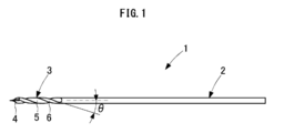
- a drill 1 according to an embodiment of the present invention includes a shank 2 for attaching the drill 1 to a drill chuck and a body 3 positioned on the tip side of the shank 2.
- the shape of the shank 2 is defined so as to match the shape of the drill chuck.
- the body 3 is provided with a front end portion 4 having two cutting edges, and a groove 5 and a land 6 that are connected to the rear of the front end portion 4 and for discharging cutting waste.
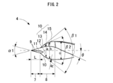
- the distal end portion 4 is provided at the most distal end, and mainly serves as a distal end positioning portion 7 that is useful for surely positioning with respect to the drilling target, and the main cutting for providing the perforation. It is comprised with the main cutting part 8 to perform.
- the tip positioning unit 7 has a tip cutting edge 9 for performing cutting to ensure the drilling position by allowing the tip positioning unit 7 positioned at the drilling position of the drilling target to enter the drilling target.
- the main cutting portion 8 has a main cutting edge 10 that continues to the rear of the tip cutting edge 9. That is, each of the two cutting edges of the front end portion 4 is composed of the most distal end cutting edge 9 and the main cutting edge 10 at the rear thereof.
- the distal end cutting edge 9 is inclined with respect to the main cutting edge 10. ing.
- the angle ⁇ ⁇ b> 1 formed by the tip cutting edge 9 indicates the tip angle of the tip cutting edge 9.
- the angle (tip angle) ⁇ 1 formed by the tip cutting edge 9 is approximately 40 °.
- the angle ⁇ 2 formed by the tip cutting edge 9 is approximately 26 °.
- the clearance angle ⁇ c of the tip cutting edge 9 is approximately 20 °.
- the rake angle of the leading edge 9 is approximately 0 °.
- the rake face 11 is connected to the rake face 12 of the main cutting edge 10 as shown in FIG.
- the tip angle of the main cutting edge 10 decreases from the front end to the rear end of the main cutting edge 10, and has a sharp angle ⁇ 1 larger than the tip angle ⁇ 1 of the tip cutting edge 9 at the front end.
- the main cutting edge 10 includes a first portion 13, a second portion 14, and a third portion 15 from the tip side.
- the first portion 13 has a constant first tip angle ⁇ 1
- the second portion 14 has a constant second tip angle ⁇ 2 smaller than the first tip angle ⁇ 1
- the third portion 15 has a first tip angle ⁇ 1. It has a third tip angle that continuously changes from two tip angles ⁇ 2 or smaller to 0 °.
- the dimensions of the tip positioning portion 7, the first portion 13, the second portion 14 and the third portion 15 of the main cutting edge 10, and the values of the first tip angle ⁇ 1 and the second tip angle ⁇ 2 are as follows. Selected.
- the tip positioning portion 7 having the tip cutting edge 9 is used.
- the main cutting edge 10 is selected so as not to contact the femur. In addition, it is selected so that drilling in such a strong oblique position can be performed efficiently and accurately.
- the angle ⁇ 1 of the tip cutting edge 9 when viewed in FIG. 2 is 40 °, and the length L in the axial direction of the tip positioning portion 7 is 2.3 mm.
- the maximum diameter a of the first portion 13 of the main cutting edge 10 is 3.2 mm, the first tip angle ⁇ 1 is 77 °, the maximum diameter b of the second portion 14 is 4.0 mm, and the second tip angle ⁇ 2 is 48 °.
- the third portion 15 has a spherical shape with a radius R of 5.0 mm, and the maximum diameter c is 4.5 mm.
- the tip angle ⁇ 1 of the tip cutting edge 9 generally falls within the range of 20 ° to 50 °.
- the drill 1 is made of, for example, stainless steel. Therefore, if the tip angle ⁇ 1 is 20 ° or more, the tip cutting edge 9 is not likely to be damaged.
- the preferred range of the tip angle ⁇ 1 is 30 ° to 50 °. This is because crushing of the cutting edge can be avoided as the tip angle ⁇ 1 is larger.
- a more preferable range of the tip angle ⁇ 1 is 35 ° to 45 °, and a more preferable range is 38 ° to 42. °.
- a preferable range of the first tip angle ⁇ 1 is 60 ° to 90 °, a more preferable range is 72 ° to 82 °, and a further preferable range is 75 ° to 79 °.
- a preferred range of the second tip angle ⁇ 2 is 43 ° to 53 °, and a more preferred range is 46 ° to 50 °.
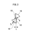
- the second clearance angle in the radial direction of the flank 16 of the main cutting edge 10 is 20 °
- the third clearance angle is 40 °
- the second clearance angle in the axial direction is 10 °
- the third clearance angle is 15 °. Is done.
- the rake angle of the main cutting edge 10 for example, an angle of around 0 ° is selected.
- the angle at which the clearance angle is easy is not limited to these values, and is arbitrarily determined in consideration of drilling efficiency, operability, drilling accuracy, and the like.
- the twist angle ⁇ is 20 °
- the web thickness is 0.9 mm
- the web taper is 1/100
- the groove width ratio is 1: 1.2.
- the margin width t is 0.4 mm
- the second sampling depth d is 0.1 mm.
- the drill 1 is typically a right-handed right-handed type and has no back taper.
- the tip positioning part 7 of the drill 1 is applied to the drilling position of the object to be drilled for positioning. At this time, even when drilling in the oblique position, the main cutting edge 10 does not contact the femur and the tip angle ⁇ 1 of the tip cutting edge 9 of the tip positioning portion 7 is about 40 °, so that positioning is easy. It can be performed.
- the cutting of the drilling is started by the tip cutting edge 9 of the tip positioning portion 7.
- the main cutting edge 10 is not yet in contact with the drilling object, and the drilling object is not kicked by the main cutting edge 10, so that the tip positioning unit 7 does not deviate from the drilling position. Get into the drilling position.
- the main cutting edge 10 comes into contact with the femur, and the main cutting edge 10 starts to contribute to the cutting.
- the tip positioning portion 7 enters the femur and secures the position of the drill 1, the drill 1 does not deviate from the drilling position even if the main cutting edge 10 contacts the drilling object.
- the front end of the main cutting edge 10 has a tip angle that is relatively large but acute as described above, the diameter of the main cutting edge 10 is effectively reduced with a relatively small cutting resistance by the portion on the front end side of the main cutting edge 10 thereafter. Cutting progresses while zooming in.
- the third portion 15 of the main cutting edge 10 contributes to the cutting, and cutting with high accuracy is sequentially performed by the small tip angle. Therefore, when cutting is completed, highly accurate drilling is completed.
- the drill 1 is reliably positioned with respect to the drilling position by the tip positioning portion 7 having the tip cutting edge 9 having a tip angle of about 40 °, and the drilling position is secured. Can do.
- the tip angle of the main cutting edge 10 is reduced as described above, the main cutting edge 10 is in contact with the drilling object even when drilling at a strong oblique position with respect to the drilling object. Therefore, it is possible to prevent the positioning of the drill 1 from being hindered or the drill 1 from deviating from the drilling position.
- the perforation can be started without any trouble.
- drilling is effectively promoted by the front end side portion of the main cutting edge 10 having a relatively large tip angle, and the tip angle of the main cutting edge 10 is increased.
- the portion on the rear end side having a small diameter the perforation can be finished with high accuracy.
- the main cutting edge 10 includes the first portion 13 and the second portion 14 having a constant tip angle, the main cutting edge 10 can be easily processed and formed.
- the tip angle is configured to continuously change from a value equal to or smaller than the tip angle of the second portion 14 to 0 °. Can be finished with.
- the front end angle of the main cutting edge 10 may be decreased continuously (overall smoothly) from the front end portion to the rear end portion of the main cutting edge 10.
- the drill 1 is not limited to medical use such as drilling of the femur but can be preferably used for drilling of resin or metal. Even when used for medical purposes, it can be preferably used for skulls other than the femur, facial bones, finger bones, and the like.
- each part of the drill 1 are not limited to the values in the above-described embodiment, and can take various values depending on the diameter of the drill 1, the application, the material of the workpiece, and the like.
Landscapes
- Health & Medical Sciences (AREA)
- Engineering & Computer Science (AREA)
- Mechanical Engineering (AREA)
- Surgery (AREA)
- Life Sciences & Earth Sciences (AREA)
- Biomedical Technology (AREA)
- Animal Behavior & Ethology (AREA)
- Orthopedic Medicine & Surgery (AREA)
- Oral & Maxillofacial Surgery (AREA)
- Heart & Thoracic Surgery (AREA)
- Medical Informatics (AREA)
- Molecular Biology (AREA)
- Nuclear Medicine, Radiotherapy & Molecular Imaging (AREA)
- General Health & Medical Sciences (AREA)
- Public Health (AREA)
- Veterinary Medicine (AREA)
- Dentistry (AREA)
- Drilling Tools (AREA)
- Surgical Instruments (AREA)
Abstract
L'invention concerne un foret (1) muni : d'un tranchant d'extrémité (9) disposé sur son extrémité ; et d'un tranchant principal (10) qui est continu vers l'arrière du tranchant d'extrémité (9). L'angle au sommet du tranchant d'extrémité (9) est un angle aigu prescrit. L'angle au sommet du tranchant principal (10) diminue de l'extrémité avant vers l'extrémité arrière du tranchant principal. L'angle au sommet sur l'extrémité avant du tranchant principal (10) est un angle aigu supérieur à l'angle au sommet du tranchant d'extrémité (9).
Priority Applications (6)
| Application Number | Priority Date | Filing Date | Title |
|---|---|---|---|
| JP2018521131A JP6375469B2 (ja) | 2016-06-22 | 2017-06-22 | ドリル |
| MYPI2018704106A MY191972A (en) | 2016-06-22 | 2017-06-22 | Drill |
| EP17815477.9A EP3476510B1 (fr) | 2016-06-22 | 2017-06-22 | Foret |
| SG11201809791YA SG11201809791YA (en) | 2016-06-22 | 2017-06-22 | Drill |
| ES17815477T ES2859273T3 (es) | 2016-06-22 | 2017-06-22 | Broca |
| US16/301,566 US10589364B2 (en) | 2016-06-22 | 2017-06-22 | Drill |
Applications Claiming Priority (2)
| Application Number | Priority Date | Filing Date | Title |
|---|---|---|---|
| JP2016123701 | 2016-06-22 | ||
| JP2016-123701 | 2016-06-22 |
Publications (1)
| Publication Number | Publication Date |
|---|---|
| WO2017222011A1 true WO2017222011A1 (fr) | 2017-12-28 |
Family
ID=60783278
Family Applications (1)
| Application Number | Title | Priority Date | Filing Date |
|---|---|---|---|
| PCT/JP2017/023021 Ceased WO2017222011A1 (fr) | 2016-06-22 | 2017-06-22 | Foret |
Country Status (7)
| Country | Link |
|---|---|
| US (1) | US10589364B2 (fr) |
| EP (1) | EP3476510B1 (fr) |
| JP (1) | JP6375469B2 (fr) |
| ES (1) | ES2859273T3 (fr) |
| MY (1) | MY191972A (fr) |
| SG (1) | SG11201809791YA (fr) |
| WO (1) | WO2017222011A1 (fr) |
Cited By (1)
| Publication number | Priority date | Publication date | Assignee | Title |
|---|---|---|---|---|
| JP2022006749A (ja) * | 2020-06-24 | 2022-01-13 | 株式会社東鋼 | 手術用ドリルビット |
Families Citing this family (9)
| Publication number | Priority date | Publication date | Assignee | Title |
|---|---|---|---|---|
| US11123808B2 (en) * | 2016-10-07 | 2021-09-21 | Mapal Fabrik Fur Prazisionswerkzeuge Dr. Kress Kg | Metal drilling tool |
| KR102370707B1 (ko) * | 2020-07-21 | 2022-03-04 | 창원대학교 산학협력단 | 복합 적층판 전용 드릴날 |
| JP7535368B2 (ja) * | 2020-09-03 | 2024-08-16 | 株式会社Subaru | ドリル及び被穿孔品の製造方法 |
| WO2022115909A1 (fr) * | 2020-12-04 | 2022-06-09 | Loggo Ip Pty Ltd | Foret hélicoïdal pour perçage d'angle peu profond |
| JP7569608B2 (ja) | 2021-01-28 | 2024-10-18 | 株式会社Subaru | ドリル及び被穿孔品の製造方法 |
| US12446897B2 (en) * | 2021-09-28 | 2025-10-21 | Wright Medical Technology, Inc. | Cutting elements |
| US12167951B1 (en) * | 2022-01-20 | 2024-12-17 | Gary Bram | Osteotomy drill bit to produce an optimally shaped jawbone opening for a dental implant and abutment |
| CN117655377B (zh) * | 2022-08-24 | 2026-07-24 | 上海钰工工具有限公司 | 阶梯钻和利用阶梯钻对工件进行钻孔切削的方法 |
| JP7398850B1 (ja) * | 2023-06-09 | 2023-12-15 | 株式会社メドメタレックス | 骨抜去器 |
Citations (8)
| Publication number | Priority date | Publication date | Assignee | Title |
|---|---|---|---|---|
| JP3940002B2 (ja) * | 2002-02-22 | 2007-07-04 | 久弥 岡崎 | 穿孔方向可変ドリル刃 |
| US20100241129A1 (en) * | 2009-03-18 | 2010-09-23 | Integrated Spinal Concepts, Inc. | Image-Guided Minimal-Step Placement Of Screw Into Bone |
| US20120093600A1 (en) * | 2010-10-15 | 2012-04-19 | Karthik Sampath | Cutting tip and rotary cutting tool employing same |
| JP2012135873A (ja) * | 2012-03-13 | 2012-07-19 | Fuji Heavy Ind Ltd | ドリル |
| US20120263548A1 (en) * | 2011-04-12 | 2012-10-18 | Richard Paul Harris | Drill bit |
| JP5341502B2 (ja) * | 2008-12-26 | 2013-11-13 | 富士重工業株式会社 | ドリル |
| US20140364855A1 (en) * | 2013-06-07 | 2014-12-11 | Lanx, Inc. | Angled instrument assembly |
| WO2015182618A1 (fr) * | 2014-05-26 | 2015-12-03 | 株式会社ビック・ツール | Foret médical |
Family Cites Families (18)
| Publication number | Priority date | Publication date | Assignee | Title |
|---|---|---|---|---|
| US2600286A (en) * | 1947-09-08 | 1952-06-10 | Bell Machine Company | Drill bit |
| US3443459A (en) * | 1968-02-14 | 1969-05-13 | Bruce Alexander Mackey | Drill |
| US3779664A (en) * | 1971-12-30 | 1973-12-18 | Boeing Co | Drill with guide tip |
| SU1156865A1 (ru) * | 1983-07-27 | 1985-05-23 | Всесоюзный заочный машиностроительный институт | Сверло |
| JPS6450911U (fr) | 1987-09-25 | 1989-03-29 | ||
| JPH0569214A (ja) * | 1991-06-04 | 1993-03-23 | Mitsubishi Materials Corp | 穴あけ工具 |
| JP2984446B2 (ja) * | 1992-01-07 | 1999-11-29 | 三菱重工業株式会社 | ドリル |
| JPH06179109A (ja) * | 1992-06-03 | 1994-06-28 | Kobayashi Design Kk | 熱可塑性合成樹脂専用ドリル |
| JP3553017B2 (ja) * | 2000-12-27 | 2004-08-11 | 強 夫馬 | ドリル |
| JP2003191211A (ja) * | 2001-12-25 | 2003-07-08 | Matsuoka Cutter Seisakusho:Kk | 回転刃物体 |
| EP2399530B1 (fr) * | 2002-08-08 | 2018-11-21 | Surgibit Ip Holdings Pty Limited | Foret de perçage |
| DE102004026014B4 (de) * | 2004-05-27 | 2008-04-17 | Horst Miebach Gmbh | Spiralbohrer |
| JP2008183626A (ja) * | 2005-11-25 | 2008-08-14 | Hamamatsu Kagaku Gijutsu Kenkyu Shinkokai | 超音波振動切削方法及びそれにより得られる繊維強化樹脂 |
| US20080085488A1 (en) * | 2006-08-29 | 2008-04-10 | Sargon Lazarof | Universal one-step drill |
| DE102008029404A1 (de) * | 2008-06-23 | 2009-12-24 | Keil Werkzeugfabrik, Karl Eischeid Gmbh | Einsatzelement, Bohrwerkzeug mit Einsatzelement und Verfahren |
| EP2390028B1 (fr) * | 2010-05-31 | 2012-12-19 | SECO TOOLS AB (publ) | Foret hélicoïdal |
| US20160228130A1 (en) * | 2015-02-09 | 2016-08-11 | Cutting Edge Medical Llc | Surgical Drill Bit |
| JP2016179543A (ja) * | 2016-07-22 | 2016-10-13 | 富士重工業株式会社 | ドリル及びドリルの製造方法 |
-
2017
- 2017-06-22 SG SG11201809791YA patent/SG11201809791YA/en unknown
- 2017-06-22 WO PCT/JP2017/023021 patent/WO2017222011A1/fr not_active Ceased
- 2017-06-22 US US16/301,566 patent/US10589364B2/en active Active
- 2017-06-22 EP EP17815477.9A patent/EP3476510B1/fr active Active
- 2017-06-22 JP JP2018521131A patent/JP6375469B2/ja active Active
- 2017-06-22 ES ES17815477T patent/ES2859273T3/es active Active
- 2017-06-22 MY MYPI2018704106A patent/MY191972A/en unknown
Patent Citations (8)
| Publication number | Priority date | Publication date | Assignee | Title |
|---|---|---|---|---|
| JP3940002B2 (ja) * | 2002-02-22 | 2007-07-04 | 久弥 岡崎 | 穿孔方向可変ドリル刃 |
| JP5341502B2 (ja) * | 2008-12-26 | 2013-11-13 | 富士重工業株式会社 | ドリル |
| US20100241129A1 (en) * | 2009-03-18 | 2010-09-23 | Integrated Spinal Concepts, Inc. | Image-Guided Minimal-Step Placement Of Screw Into Bone |
| US20120093600A1 (en) * | 2010-10-15 | 2012-04-19 | Karthik Sampath | Cutting tip and rotary cutting tool employing same |
| US20120263548A1 (en) * | 2011-04-12 | 2012-10-18 | Richard Paul Harris | Drill bit |
| JP2012135873A (ja) * | 2012-03-13 | 2012-07-19 | Fuji Heavy Ind Ltd | ドリル |
| US20140364855A1 (en) * | 2013-06-07 | 2014-12-11 | Lanx, Inc. | Angled instrument assembly |
| WO2015182618A1 (fr) * | 2014-05-26 | 2015-12-03 | 株式会社ビック・ツール | Foret médical |
Cited By (2)
| Publication number | Priority date | Publication date | Assignee | Title |
|---|---|---|---|---|
| JP2022006749A (ja) * | 2020-06-24 | 2022-01-13 | 株式会社東鋼 | 手術用ドリルビット |
| JP7121407B2 (ja) | 2020-06-24 | 2022-08-18 | 株式会社東鋼 | 手術用ドリルビット |
Also Published As
| Publication number | Publication date |
|---|---|
| SG11201809791YA (en) | 2018-12-28 |
| US20190299302A1 (en) | 2019-10-03 |
| JP6375469B2 (ja) | 2018-08-15 |
| EP3476510B1 (fr) | 2020-12-23 |
| MY191972A (en) | 2022-07-21 |
| EP3476510A4 (fr) | 2020-02-12 |
| US10589364B2 (en) | 2020-03-17 |
| JPWO2017222011A1 (ja) | 2018-08-02 |
| EP3476510A1 (fr) | 2019-05-01 |
| ES2859273T3 (es) | 2021-10-01 |
Similar Documents
| Publication | Publication Date | Title |
|---|---|---|
| JP6375469B2 (ja) | ドリル | |
| JP7078825B2 (ja) | ドリル | |
| JP6848176B2 (ja) | ドリル | |
| JP6556229B2 (ja) | ドリルおよび切削加工物の製造方法 | |
| US20170232529A1 (en) | Drill | |
| JP5940208B1 (ja) | ドリル | |
| JP5087735B2 (ja) | ドリル | |
| JPWO2019049257A1 (ja) | ドリル | |
| JP6235737B2 (ja) | 3枚刃ドリル | |
| US10993728B2 (en) | Precision bone drill bit | |
| US10882121B2 (en) | Drill and method for manufacturing machined product | |
| CN104159692B (zh) | 螺旋丝锥 | |
| JP6975353B1 (ja) | ドリル | |
| JP2012135873A (ja) | ドリル | |
| JP2017087342A (ja) | ツイストドリル | |
| JP2005177891A (ja) | ドリル | |
| JP4206778B2 (ja) | センタドリル | |
| JP3199122U (ja) | バリの発生を抑制するドリル | |
| JP4015034B2 (ja) | 小径ドリル | |
| JPH0740119A (ja) | 穴明け工具 | |
| JP3119919U (ja) | 難削材用穴明けドリル | |
| JP4580325B2 (ja) | リーマ及びドリル並びに加工方法 | |
| JP2005138258A (ja) | ドリル | |
| JP4179171B2 (ja) | スローアウェイ式ドリル及びスローアウェイチップ | |
| JP2005022012A (ja) | ドリル |
Legal Events
| Date | Code | Title | Description |
|---|---|---|---|
| ENP | Entry into the national phase |
Ref document number: 2018521131 Country of ref document: JP Kind code of ref document: A |
|
| 121 | Ep: the epo has been informed by wipo that ep was designated in this application |
Ref document number: 17815477 Country of ref document: EP Kind code of ref document: A1 |
|
| NENP | Non-entry into the national phase |
Ref country code: DE |
|
| ENP | Entry into the national phase |
Ref document number: 2017815477 Country of ref document: EP Effective date: 20190122 |