WO2017222049A1 - Outil électrique - Google Patents
Outil électrique Download PDFInfo
- Publication number
- WO2017222049A1 WO2017222049A1 PCT/JP2017/023206 JP2017023206W WO2017222049A1 WO 2017222049 A1 WO2017222049 A1 WO 2017222049A1 JP 2017023206 W JP2017023206 W JP 2017023206W WO 2017222049 A1 WO2017222049 A1 WO 2017222049A1
- Authority
- WO
- WIPO (PCT)
- Prior art keywords
- switch
- operation unit
- housing
- motor
- reference position
- Prior art date
- Legal status (The legal status is an assumption and is not a legal conclusion. Google has not performed a legal analysis and makes no representation as to the accuracy of the status listed.)
- Ceased
Links
Images








Classifications
-
- B—PERFORMING OPERATIONS; TRANSPORTING
- B24—GRINDING; POLISHING
- B24B—MACHINES, DEVICES, OR PROCESSES FOR GRINDING OR POLISHING; DRESSING OR CONDITIONING OF ABRADING SURFACES; FEEDING OF GRINDING, POLISHING, OR LAPPING AGENTS
- B24B23/00—Portable grinding machines, e.g. hand-guided; Accessories therefor
-
- B—PERFORMING OPERATIONS; TRANSPORTING
- B25—HAND TOOLS; PORTABLE POWER-DRIVEN TOOLS; MANIPULATORS
- B25F—COMBINATION OR MULTI-PURPOSE TOOLS NOT OTHERWISE PROVIDED FOR; DETAILS OR COMPONENTS OF PORTABLE POWER-DRIVEN TOOLS NOT PARTICULARLY RELATED TO THE OPERATIONS PERFORMED AND NOT OTHERWISE PROVIDED FOR
- B25F5/00—Details or components of portable power-driven tools not particularly related to the operations performed and not otherwise provided for
-
- B—PERFORMING OPERATIONS; TRANSPORTING
- B25—HAND TOOLS; PORTABLE POWER-DRIVEN TOOLS; MANIPULATORS
- B25F—COMBINATION OR MULTI-PURPOSE TOOLS NOT OTHERWISE PROVIDED FOR; DETAILS OR COMPONENTS OF PORTABLE POWER-DRIVEN TOOLS NOT PARTICULARLY RELATED TO THE OPERATIONS PERFORMED AND NOT OTHERWISE PROVIDED FOR
- B25F5/00—Details or components of portable power-driven tools not particularly related to the operations performed and not otherwise provided for
- B25F5/02—Construction of casings, bodies or handles
-
- H—ELECTRICITY
- H01—ELECTRIC ELEMENTS
- H01H—ELECTRIC SWITCHES; RELAYS; SELECTORS; EMERGENCY PROTECTIVE DEVICES
- H01H3/00—Mechanisms for operating contacts
- H01H3/02—Operating parts, i.e. for operating driving mechanism by a mechanical force external to the switch
- H01H3/20—Operating parts, i.e. for operating driving mechanism by a mechanical force external to the switch wherein an auxiliary movement thereof, or of an attachment thereto, is necessary before the main movement is possible or effective, e.g. for unlatching, for coupling
-
- H—ELECTRICITY
- H01—ELECTRIC ELEMENTS
- H01H—ELECTRIC SWITCHES; RELAYS; SELECTORS; EMERGENCY PROTECTIVE DEVICES
- H01H9/00—Details of switching devices, not covered by groups H01H1/00 - H01H7/00
- H01H9/02—Bases, casings, or covers
- H01H9/06—Casing of switch constituted by a handle serving a purpose other than the actuation of the switch, e.g. by the handle of a vacuum cleaner
-
- B—PERFORMING OPERATIONS; TRANSPORTING
- B25—HAND TOOLS; PORTABLE POWER-DRIVEN TOOLS; MANIPULATORS
- B25D—PERCUSSIVE TOOLS
- B25D2250/00—General details of portable percussive tools; Components used in portable percussive tools
- B25D2250/255—Switches
Definitions
- the present disclosure relates to an electric tool in which a motor is housed in a housing having a cylindrical grip portion that can be gripped by a user.
- a part of the housing of the power tool in which the motor is accommodated is usually a cylinder that can be gripped by the user so that the user can operate the power tool while gripping the power tool. It is formed in a shape.
- a switch in the housing can be turned on or off to switch between driving and stopping of the motor.
- An operation unit is provided for the user to perform a pulling operation with a finger (see, for example, Patent Document 1 below).
- This operation unit is provided with a long member on the front end side or rear end side in the central axis direction of the grip part that can be gripped by the user.
- the first end of the long member is pivotally supported, and the second end of the long member is open.
- this type of operation unit is referred to as a paddle switch.
- the user can push the paddle switch into the housing and turn on the switch by grasping the paddle switch when gripping the grip portion.
- the paddle switch described in Patent Document 1 is engaged with the paddle switch at the reference position before the pulling operation so that the user does not perform the pulling operation carelessly, and the switch in the housing is turned off.
- a lock-off mechanism for maintaining the state is provided.
- the above-described paddle switch can swing around its axis when the first end of the paddle switch is pivotally supported by the housing.
- the lock-off mechanism holds the switch in the housing in the off state.
- the second end of the paddle switch projects from the outer surface of the housing.
- the length of the paddle switch is increased so that the paddle switch can be operated in the entire gripping portion of the housing (in other words, to improve operability), the amount of protrusion from the outer surface of the housing increases.
- the user grips the gripping portion at an arbitrary position where the workpiece is easily processed.
- the paddle switch has a force required to perform a pulling operation according to the gripping position. (In other words, the load) changes.
- One aspect of the present disclosure is desirably capable of providing an electric tool in which a motor and a motor driving switch are housed in a housing, and a user can easily operate the switch while holding the housing.
- An electric tool includes a motor, a switch configured to operate energization of the motor, and a cylindrical grip portion that can be gripped by a user of the electric tool.
- the operation part is provided in the grip part of the housing so that it can be displaced.
- the operation unit switches the switch from the off state to the on state by moving from the reference position to the operation position by an external operation.
- the operation unit constitutes a part of the outer surface of the gripping unit.
- the operation unit can be moved from the reference position to the operation position by an external operation, and the switch can be switched from the off state to the on state by the movement. Further, when the external operation is stopped, the operation unit returns to the reference position and returns the switch to the off state.
- the operation part forms a part of the outer surface of the grip part
- the switch in the housing is turned from the OFF state to the ON state by moving from the reference position to the operation position by the operation by the user. Switch to.
- the operation unit constitutes a part of the outer surface of the gripping unit, the load applied to the operation unit to turn on the switch is almost constant regardless of the position of the gripping unit. It is possible to suppress a decrease in operability depending on a gripping position for gripping the part.
- the operation unit When the external operation is stopped, the operation unit returns to the reference position and switches the switch to the off state. For this reason, the user can stop the drive of the motor simply by stopping the operation of the operation unit, and suppresses the motor from being driven continuously even though the user stopped the operation of the operation unit. it can. That is, it can suppress that a motor rotates contrary to a user's intention, and can improve the usability of an electric tool.
- the power tool may include a lock-off mechanism configured to fix the operation unit to the reference position and hold the switch in an off state, and to release the fixing of the operation unit to the reference position by an external operation. .
- the lock-off mechanism may be configured to automatically fix the operation unit at the reference position without performing an external operation when the operation unit returns from the operation position to the reference position. If the lock-off mechanism is configured in this manner, it is possible to better suppress the operation unit moving against the user's intention, the switch being turned on, and the motor being driven.
- the operation unit may be configured to be displaceable along the central axis of the gripping unit.
- the operation unit can move (slide) in the direction of the central axis of the housing along the outer surface of the housing. For this reason, the user can switch the switch from the off state to the on state by sliding the operation unit.
- the lock-off mechanism is provided in the housing so as to be swingable about an axis orthogonal to the displacement direction of the operation portion, and is configured to fix the operation portion to a reference position at a predetermined swing position. Also good.
- the user can release the fixing of the operation unit to the reference position by swinging the lock-off mechanism from the outside of the housing while holding the grip unit.
- the switch can be turned on by sliding operation.
- an intermediate member may be provided in the housing between the movable unit of the switch and the operation unit. That is, when the operation unit moves to the operation position, the intermediate member depresses the movable part of the switch and switches the switch from the off state to the on state.
- the direction of the switch in the housing can be arbitrarily set without being restricted by the moving direction of the operation unit, and the degree of freedom in designing the electric tool can be increased.
- the lock-off mechanism may be provided in the grip portion so as to be rotatable around the central axis of the grip portion, and may be configured to fix the operation portion to a reference position at a predetermined rotation position. In this way, by rotating the lock-off mechanism around the central axis of the gripping part, the fixing of the operation part to the reference position is released, and the operation part is moved from the reference position to the operation position by an external operation. Will be able to.
- the operation unit may be configured to be displaceable to the inside of the gripping unit when the lock-off mechanism is rotated and the fixing to the reference position is released. In this way, the user can directly depress the movable part of the switch in the housing by displacing the operation part to the inside of the grip part by gripping the grip part.
- the operation part can be displaced along the center axis of the gripping part. It may be configured.
- the power tool described above may be configured to drive the motor with power supplied from an AC power source such as a commercial power source when the switch is on, or power supplied from a battery that can be attached to the housing. It may be configured to drive the motor.
- an AC power source such as a commercial power source when the switch is on, or power supplied from a battery that can be attached to the housing. It may be configured to drive the motor.
- the operation unit may be arranged so as to extend over the outer surface of the gripping unit, and the load required for the external operation may be constant regardless of which position of the operation unit is operated.
- the operation unit may be arranged so as to extend over the outer surface of the gripping unit, and the entire operation unit may be displaced by the same movement amount by an external operation.
- the entire operation unit is displaced by the same amount of movement, and the load applied to the operation unit to turn on the switch is constant. It can suppress that operativity falls by a position.
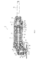
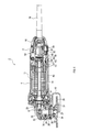
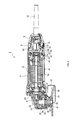
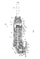
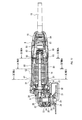
- FIG. 4 is a cross-sectional view illustrating a state in which the fixing of the operation unit by the lock-off mechanism is released in FIG. 3.
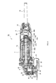
- FIG. 6 is a cross-sectional view illustrating a state where an operation unit is operated and moved to an operation position in FIG. 5. It is sectional drawing showing the internal structure of the grinder of 2nd Embodiment.
- FIG. 8 is a cross-sectional view illustrating a state in which fixing of the operation unit by the lock-off mechanism is released in FIG.
- FIG. 9 is a cross-sectional view illustrating a state where an operation unit is operated and moved to an operation position in FIG. 8. It is sectional drawing showing the internal structure of the grinder of 3rd Embodiment. It is sectional drawing showing the state which cancelled
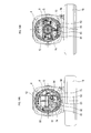
- FIG. 14B is a cross-sectional view taken along the line XIVB-XIVB shown in FIG. 15A and 15B are cross-sectional views illustrating states in which the lock of the operation unit by the lock-off mechanism is released in FIGS. 14A and 14B, respectively.
- 16A and 16B are cross-sectional views illustrating a state where the operation unit is operated and moved to the operation position in FIGS. 15A and 15B, respectively.
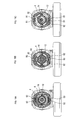
- 18A is a sectional view taken along line XVIIIA-XVIIIA shown in FIG. 17,
- FIG. 18B is a sectional view taken along line XVIIIB-XVIIIB shown in FIG. 17, and FIG.
- FIG. 18C is a sectional view taken along line XVIIIC-XVIIIC shown in FIG.
- FIG. 18 is a cross-sectional view illustrating a state where an operation unit is operated and moved to an operation position in FIG. 17.
- 20A is a sectional view taken along line XXA-XXA shown in FIG. 19
- FIG. 20B is a sectional view taken along line XXB-XXB shown in FIG. 19
- FIG. 20C is a sectional view taken along line XXC-XXC shown in FIG. It is a perspective view showing the external appearance of a rechargeable grinder.
- torsion coil spring 46, 49A, 49B, 57A, 57B, 63, 74 ... Projection, 47A, 47B ... Projection piece, 50 ... Switch, 51 ... Movable part, 52 ... Intermediate member, 53 ... Support shaft, 54, 66, 93 ... Compression coil spring, 56 ... Inner hole, 58, 72, 92 ... support hole, 61, 82 ... collar, 62 ... support part, 76 ... case, 81 ... end, 83 ... connecting part, 84 ... pressing part, 91 ... insertion hole, 100 ... Battery pack
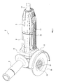
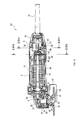
- the grinder 2 of this embodiment includes a motor housing 4, a gear housing 6, a rear housing 8, and a wheel cover 10.
- the motor housing 4 has a cylindrical shape having an outer diameter that can be grasped by a user with one hand, and houses a motor 12 therein as shown in FIG.
- the motor 12 is disposed in the motor housing 4 such that the rotation shaft 14 of the motor 12 is parallel to and substantially coincides with the central axis of the motor housing 4, and the rotation shaft 14 of the motor 12 faces the gear housing 6. It is protruding.
- the rear housing 8 has a substantially cylindrical shape like the motor housing 4 and is provided on one end side of the central axis of the motor housing 4 (specifically, on the side opposite to the gear housing 6).
- a power supply wiring portion 16 is accommodated in the rear housing 8.
- the gear housing 6 side of the central axis of the gear housing 6 (in other words, the rotating shaft 14 of the motor 12) is referred to as the front, and the rear housing side is referred to as the rear.
- the power supply wiring portion 16 is projected from the rear of the rear housing 8 and energizes the motor 12 with power supplied from the external AC power supply (commercial power supply) and power supplied from the power supply cord 18.
- a switch 50 is provided. The switch 50 is turned on or off via the operation unit 40 operated by the user.
- the operation unit 40 has an elongated shape, and the central axis direction of the motor housing 4 and the rear housing 8 is configured to be a part of the outer surface of the motor housing 4 and the rear housing 8. It is provided so that it may become the longitudinal direction.
- the operation unit 40 is movable along the central axes of the motor housing 4 and the rear housing 8 (in other words, in the longitudinal direction of the operation unit 40). It is arranged at a reference position on the front side (see FIGS. 2 and 3).
- the operation unit 40 switches the switch 50 from the off state to the on state.
- the motor 12 is energized and rotated when the switch 50 is on.
- the gear housing 6 is provided on the opposite side of the motor housing 4 from the rear housing 8 (that is, the front side of the grinder 2), and the first bevel gear 20, the second bevel gear 22, the spindle 24, the bearings 26, 28, etc. Contained.
- the first bevel gear 20 is fixed to the rotating shaft 14 of the motor 12 in the gear housing 6.
- the second bevel gear 22, the spindle 24, and the bearings 26 and 28 are integrally provided in an internal housing 30 that is separate from the gear housing 6, and the internal housing 30 is fitted and fixed in the gear housing 6. Is accommodated in the gear housing 6.
- the inner housing 30 is provided with a spindle 24 through a bearing 26 so as to be rotatable.
- the inner housing 30 has a cylindrical shape coaxial with the central axis of the spindle 24, and is fixed in the gear housing 6 so that the spindle 24 is orthogonal to the rotating shaft 14 of the motor 12.
- the second bevel gear 22 is fixed to the spindle 24, meshes with the first bevel gear 20 in the gear housing 6, and converts the rotational output of the motor 12 into a rotational force around the axis of the spindle 24.
- the first end of the spindle 24 is rotatably supported by the gear housing 6 via a bearing 28, and the second end of the spindle 24 is externally (downward) from the inner housing 30 (in other words, the gear housing 6). ).
- An inner flange 32 for positioning and fixing the disc-shaped tip tool 36 is provided on the protruding portion of the spindle 24 from the gear housing 6. Further, a screw portion 25 for screwing the lock nut 34 is formed on the outer peripheral portion of the tip of the spindle 24 further than the inner flange 32. The lock nut 34 holds the tip tool 36 between the lock nut 34 and the inner flange 32.
- the motor 12 rotates, and the rotation output is transmitted via the gear mechanism (the first bevel gear 20 and the second bevel gear 22) in the gear housing 6. It is transmitted to the spindle 24.
- the tip tool 36 fixed to the spindle 24 via the lock nut 34 rotates, and operations such as grinding, polishing, and cutting can be performed.
- a grinding wheel, a cutting wheel, a wire brush, and the like can be given as the tip tool 36 used in the grinder 2 as described above.
- the gear housing 6 is detachably provided with a handle portion 9 that is gripped by a user when the grinder 2 is used.
- the wheel cover 10 is provided on the grinder 2 in order to protect the user from scattering of workpieces and fragments of the tip tool 36 that occur during operations such as grinding, polishing, and cutting.
- the wheel cover 10 is formed in a substantially semicircular shape so as to cover a part of the tip tool 36 fixed to the spindle 24 (substantially half of the tip tool 36 in this embodiment) on the gear housing 6 side. Yes.
- the wheel cover 10 is fixed to a portion of the inner housing 30 where the spindle 24 protrudes. That is, in the inner housing 30, the attachment portion 31 for attaching the wheel cover 10 has a cylindrical shape that is coaxial with the central axis of the spindle 24 and surrounds the spindle 24.
- an outer periphery of the attachment portion 31 of the inner housing 30 is provided at a central portion of a semicircular plate surface disposed opposite to the plate surface of the tip tool 36 on the inner housing 30 side of the tip tool 36.
- a mounting portion 37 is provided for fixing to the head.
- the attachment portion 37 has an annular shape that can be fitted to the attachment portion 31 of the inner housing 30, and a part of the ring is opened so that the attachment portion 37 can be fastened and fixed around the attachment portion 31 by the fastener 38. It has become. Note that the configuration of the mounting portion 37 is common in grinders, and therefore, detailed description thereof is omitted.
- the wheel cover 10 can be detachably attached to the inner housing 30. Further, the wheel cover 10 can be rotated around the spindle 24 by loosening the tightening of the inner housing 30 by the mounting portion 37, and can be protected by the plate surface of the semicircular wheel cover 10. You can change the area.
- the reason why the protection area can be changed in this way is that the area where the tip tool 36 should be exposed as viewed from the grinder 2 differs depending on the use of the tip tool 36 (grinding, polishing, cutting).
- the position of the wheel cover 10 can be changed according to the contents.
- the length of the operation portion 40 in the longitudinal direction is set to a length that allows the user to operate the motor housing 4 and the rear housing 8 even if the user changes the gripping position.
- the motor housing 4 and the rear housing 8 are gripping portions that can be gripped by the user over substantially the entire outer periphery around the central axis thereof, and the operation portion 40 is gripped by the user. Can be operated.
- the operation unit 40 has an upper surface opened by a plate surface for constituting a part of the outer surfaces of the housings 4 and 8 and a frame portion erected from the outer peripheral edge of the plate surface toward the inside of the housing. It has a flat box shape.
- the motor housing 4 and the rear housing 8 are provided with openings that support the operation unit 40 so as to be displaceable along the central axis.
- two pins 44 and 48 are provided at predetermined intervals along the longitudinal direction of the operation unit 40 on the rear frame portion disposed on the rear housing 8 side. These pins 44 and 48 are arranged so as to be orthogonal to the longitudinal direction of the operation unit 40 (in other words, the direction along the central axis of the rear housing 8).
- a swinging member 42 is provided that can swing around the center.
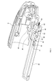
- the swing member 42 has a main body portion protruding from the pin 44 to the rear side of the grinder 2, and a pair of L-shaped guide holes 56 (see FIG. 4, only one of the pair of guide holes 56 is inserted), thereby providing a protrusion 46 that fixes the operation unit 40 to the rear housing 8 so as to be displaceable.
- Each of the guide holes 56 includes a straight portion that supports the projection 46 so as to be movable along the central axis of the rear housing 8 and a bent portion that is bent toward the inside of the rear housing 8 on the front side of the straight portion. It is formed in an L shape.
- the main body portion of the swing member 42 is urged toward the inside of the rear housing 8 by the urging force of the torsion coil spring 45 wound around the pin 44.
- the rear housing 8 is provided with a compression coil spring 54 for urging the operation portion 40 from the rear side to the front side of the rear housing 8.
- the operation unit 40 is fixed to the reference position on the front side of the grinder 2 by the urging force of the compression coil spring 54 when not operated by the user. In this state, the protrusion 46 of the swinging member 42 enters the bent portion of the guide hole 56 and the movement of the operation unit 40 to the rear side is prevented.
- the swinging member 42 is integrally provided with an operation protrusion 43 that protrudes from the pin 44 toward the front outer side of the rear housing 8. Is formed.
- the protrusion 43 is operated by a user pushing the inside from the outside of the operation unit 40 to rotate the swinging member 42 against the urging force of the torsion coil spring 45. This is for releasing the fixing of the unit 40 to the reference position so that the operation unit 40 can be operated.
- an opening 41 for projecting the tip portion of the projecting piece 43 to the outside of the housings 4, 8 is provided on the plate surface constituting the outer surface of the housings 4, 8.
- the switch 50 is provided so that the movable portion 51 for turning on or off the contact point faces the operation portion 40. And between the movable part 51 of the switch 50 and the operation part 40, it is displaced in the direction orthogonal to the moving direction (in other words, the operation direction of the operation part 40) by the movement of the operation part 40 to the rear.
- An intermediate member 52 that switches the switch 50 from the off state to the on state is provided.
- the intermediate member 52 is a rectangular plate-like member disposed along the central axis of the rear housing 8 and is curved outward with respect to the central axis of the rear housing 8.
- the intermediate member 52 is provided with a support shaft 53 at the front end edge of the rear housing 8 for supporting the intermediate member 52 so as to be swingable.
- the support shaft 53 is inserted into a pair of support holes 58 provided in the rear housing 8 (only one of the pair of support holes 58 is shown in FIG. 4), so that the pin of the operation unit 40 is inserted. 48 so as to be substantially parallel to 48.
- the plate surface of the intermediate member 52 on the operation unit 40 side is in contact with the pin 48.
- the switch 50 is arranged so that the operation direction of the switch 50 is orthogonal to the movement direction of the operation unit 40, and therefore, the movement direction of the operation unit 40 is changed by the intermediate member 52. The direction is changed and the switch 50 is turned on.
- the operation unit 40 for turning on or off the switch 50 is one of the outer surfaces of the motor housing 4 and the rear housing 8 that are gripping portions that can be gripped by the user. Part.
- the operation unit 40 has a long shape so that the user can operate with a constant load no matter where the user holds the motor housing 4 or the rear housing 8, and the operation unit 40 can be operated by an external operation by the user.
- the whole 40 moves along the central axis of each housing 4 and 8 with the same movement amount.
- the operation unit 40 is normally fixed at a reference position by the engagement of the swing member 42 constituting the lock-off mechanism and the guide hole 56, and when the user pushes the protruding piece 43 of the swing member 42, The fixing of the operation unit 40 is released, and the operation unit 40 can be operated.
- the user can operate the operation unit 40 while holding the desired positions of the motor housing 4 and the rear housing 8. Further, this operation only needs to move the operation unit 40 backward against the urging force of the compression coil spring 54, and the force required for the operation becomes constant even if the gripping position changes.
- the force required to operate the operation unit varies depending on the gripping positions of the motor housing 4 and the rear housing 8 as in the case where the operation unit is configured by the paddle switch described above. And it can suppress that the operation becomes difficult.
- the operation unit 40 does not need to protrude outward from the outer peripheral surface of the motor housing 4 or the rear housing 8, so that each of the housings 4, 8 is made thin so that the grinder 2 as a whole. Can be miniaturized.
- the operation unit 40 returns to the reference position by the urging force of the compression coil spring 54. In this state, if the user does not perform an operation of pushing in the protrusion 43 of the swing member 42, the swing member 42 is rotated by the biasing force of the torsion coil spring 45, and the operation unit 40 is moved to the reference position. Fixed to.
- the user can switch the switch 50 to the OFF state by stopping the operation of the operation unit 40 to stop the driving of the motor 12, and can keep the state. Therefore, according to the grinder 2 of this embodiment, it can suppress that the motor 12 rotates contrary to a user's intention, and can improve the usability of the grinder 2.
- an intermediate member 52 that swings due to the displacement of the operation unit 40 is provided between the operation unit 40 and the switch 50. Therefore, according to the grinder 2 of the present embodiment, the backward movement of the operation unit 40 by the user's operation is changed by the intermediate member 52 in a direction orthogonal to the moving direction, and the movable unit of the switch 50 51 can be pressed.
- the arrangement direction of the switch 50 in the rear housing 8 can be arbitrarily set without corresponding to the operation direction of the operation unit 40, and the degree of freedom in design can be increased.
- the basic configuration of the grinder 2A of the second embodiment is the same as that of the grinder 2 of the first embodiment.
- the grinder 2A is different from the grinder 2 in the configuration of an operation unit 40A for turning on or off the switch 50 and a lock-off mechanism.
- the operation unit 40A of the present embodiment has a long shape so that the user can operate the motor housing 4 and the rear housing 8 regardless of the position of the user. .
- the motor housing 4 and the rear housing 8 are provided with openings for supporting the operation portion 40A so as to be displaceable, and the operation portion 40A is attached so as to close the openings.
- the switch 50 provided in the rear housing 8 is arranged so that the movable portion 51 faces rearward, and the movable portion 51 is moved to the front end of the operation portion 40A by moving the operation portion 40A forward.
- a plate-like protrusion 49A for direct pressing is provided.
- the operation unit 40A is normally arranged at the reference position by the projection 49A being urged from the movable unit 51 of the switch 50 in the direction in which the switch 50 is turned off (that is, the rear side of the grinder 2).
- the operation unit 40A is provided with a swinging member 42A for fixing the operation unit 40A at the reference position.
- the operation unit 40A has a flat box shape with an open upper surface, like the operation unit 40 of the first embodiment. Further, a support shaft 44A protrudes from the swing member 42A so as to be orthogonal to the longitudinal direction of the operation portion 40A.
- the swing member 42A is swingably attached to the operation portion 40A by inserting the support shaft 44A into a support hole (not shown) provided in the frame portion of the operation portion 40A.
- the swinging member 42A is provided with a protruding piece 43A for operation and a protruding piece 47A for fixing.
- the operating protrusion 43A protrudes to the outside from the opening 41A provided in the operating portion 40A when the operating portion 40A is at the reference position.
- the fixing protrusion 47A comes into contact with a protrusion 57A provided on the case of the motor 12 when the operation portion 40A is at the reference position.
- a torsion coil spring 45A for biasing the protruding piece 47A toward the case side of the motor 12 (in other words, inside the rear housing 8) is provided.
- the operation unit 40A is not only disposed at the reference position by the urging force from the movable unit 51 of the switch 50, but also the protrusion of the swinging member 42A when the user is not operating the operation unit 40A.
- the piece 47A is fixed to the reference position by contacting the protrusion 57A of the motor 12.
- the switch 50 is locked in the off state, and the user cannot operate the operation unit 40A to switch the switch 50 to the on state.
- the protrusion 43A of the swing member 42A is operated in this state to rotate the swing member 42A against the urging force of the torsion coil spring 45A, as shown in FIG.
- the engagement between the protruding piece 47A of 42A and the protrusion 57A of the motor 12 is released.
- the user can move the operation unit 40A to the front of the grinder 2A, and by this movement, the user presses the movable part of the switch 50 via the protrusion 49A.
- the switch 50 can be switched from the off state to the on state.
- the user can turn on the switch 50 and rotate the motor 12 by substantially the same operation as that of the grinder 2 of the first embodiment.
- the same effect as that of the first embodiment can be obtained.
- the grinder 2A of the present embodiment is configured to directly press the movable portion 51 of the switch 50 by the protrusion 49A of the operation portion 40A without providing the intermediate member 52 between the operation portion 40A and the switch 50. Yes. For this reason, in this embodiment, a number of parts can be decreased compared with 1st Embodiment.
- the operation unit 40A is configured to move to the reference position by the urging force from the movable unit 51 of the switch 50.
- the operation unit 40A is urged from the urging member such as the compression coil spring 54. You may comprise so that it may move to a reference position with a force.
- the basic configuration of the grinder 2B of the third embodiment is the same as that of the grinder 2A of the second embodiment.
- the grinder 2B is different from the grinder 2A in the arrangement of the switch 50 and the operation direction of the operation unit 40B. Therefore, in this embodiment, differences from the second embodiment will be described, and descriptions of other parts will be omitted.
- the switch 50 is provided in the rear housing 8 so that the movable portion 51 faces the front of the grinder 2B.
- the operation unit 40B has a long shape, like the operation unit 40A of the second embodiment, and constitutes part of the outer surfaces of the motor housing 4 and the rear housing 8.
- the operation unit 40B can be displaced along the central axes of the motor housing 4 and the rear housing 8, but in this embodiment, the projection 49B provided on the rear end side of the operation unit 40B causes the operation unit 40B to move backward from the reference position.
- the switch 50 is turned on by moving to.
- the protrusion 49B moves forward by the biasing force from the movable unit 51 of the switch 50 and is held at the reference position, and the operation unit 40B is moved backward from the reference position by an external operation.
- the movable part 51 is pressed by moving to.
- the switch 50 is turned on.
- the operating portion 40B is provided with a swing member 42B having the same configuration as the swing member 42A of the second embodiment.
- the swing member 42B includes an operation protrusion 43B and a fixing protrusion 47B, and is attached to the operation portion 40B in the opposite direction to the second embodiment via a support shaft 44B. Further, the swing member 42B is urged in the direction opposite to that of the second embodiment by a torsion coil spring 45B provided around the support shaft 44B.
- the operation protrusion 43B protrudes outside from the opening 41B provided in the operation unit 40B when the operation unit 40B is at the reference position.
- the fixing protrusion 47B comes into contact with a protrusion 57B provided on the case of the motor 12 when the operation portion 40B is at the reference position.
- the operation unit 40B is arranged at the reference position by the urging force from the movable unit 51 of the switch 50 in a normal time when the user does not operate the operation unit 40B, and the protruding piece 47B of the swing member 42B is a motor. By being in contact with the twelve protrusions 57B, the reference position is fixed.
- the user can move the operation unit 40B to the rear of the grinder 2B, and by this movement, the user presses the movable unit of the switch 50 via the protrusion 49B.
- the switch 50 can be switched from the off state to the on state.
- the user can switch the switch 50 to the on state and rotate the motor 12 by substantially the same operation as that of the grinders 2 and 2A of the respective embodiments.
- the same effects as those in the above embodiments can be obtained.
- the basic configuration of the grinder 2C of the fourth embodiment is the same as that of the grinder 2 of the first embodiment.
- the grinder 2 is different from the grinder 2 in the configuration of the operation unit 60 for turning on or off the switch 50 and the lock-off mechanism.
- the switch 50 is arranged in a direction in which the movable portion 51 is orthogonal to the central axis of the rear housing 8 (specifically, the lower part from which the spindle 24 protrudes from the gear housing 6), as in the first embodiment. It is arranged to face.
- the operation unit 60 has a long and long shape along the central axis of the rear housing 8, and is provided on the outer peripheral surface of the rear housing 8 at a position facing the movable unit 51 of the switch 50.
- the operation unit 60 rotates the operation unit 60 around the central axis of the rear housing 8 by twisting the gripped hand when the user grips the gripping part which is the outer peripheral surface of the motor housing 4 and the rear housing 8. It is configured to be able to move.
- the rear housing 8 has an arcuate support hole that supports the operation unit 60 so that the operation unit 60 can be rotated within a predetermined angle range about the central axis O.
- 72 is provided.
- the support hole 72 is provided with a hollow support portion 62 that is inserted into the support hole 72 and is rotatable about the central axis O.
- the support portion 62 includes a plate-like member having an arc-shaped cross section, and has a hollow portion into which the operation portion 60 can be inserted at the center of the plate surface. Then, both ends of the arc are inserted into the support holes 72 provided in the rear housing 8 across the hollow portion, and the support portion 62 can be rotated around the center axis O of the rear housing 8.
- the operation part 60 is fixed to the rear housing 8 by being inserted into the hollow part of the support part 62 from the inside of the rear housing 8. For this reason, the operation part 60 can be rotated around the central axis O of the rear housing 8 together with the support part 62.
- the operation unit 60 has a flat box shape with an upper surface opened, like the operation unit 40 of the first embodiment, and a flange portion 61 extending in the outer peripheral direction on the opening end side of the frame portion constituting the box. Is provided.
- the operation portion 60 when the operating portion 60 is inserted into the hollow portion of the support portion 62 from the inside of the rear housing 8, the operation portion 60 does not come out of the rear housing 8, and the rear housing 8 is within the hollow portion of the support portion 62. Can be displaced in the radial direction perpendicular to the central axis O of the.
- a compression coil spring 66 is provided at the center in the longitudinal direction of the operation unit 60.
- One end of the compression coil spring 66 is fixed to the case 76 of the motor 12, and the compression coil spring 66 urges the entire operation unit 60 from the inside to the outside of the rear housing 8.
- the operation unit 60 is in a state of protruding from the support unit 62 by the urging force of the compression coil spring 66 in a normal time when the operation unit 60 is not operated by the user, and the user can operate the operation unit 60 by an external operation. 60 can be pushed into the rear housing 8.
- the operation unit 60 is rotated around the central axis O of the rear housing 8, and the center position of the operation unit 60 in the rotation direction is movable.
- a protrusion 63 is provided to allow the movable portion 51 to be pressed when facing the portion 51.
- the projection 63 receives the urging force from a torsion coil spring 64 attached to the rear end of the case of the motor 12, thereby rotating the entire operation unit 60 from a position where the projection 63 faces the movable portion 51 of the switch 50.
- this rotation stop position is the reference position of the operation unit 60.
- the support hole 72 and the support part 62 are located at a position where the projection 63 faces the movable part 51 of the switch 50 when the operation part 60 is rotated against the urging force of the torsion coil spring 64. Stops rotating.
- the switch 50 is locked in the off state, and in the present embodiment, the protrusion 74 and the flange portion 61 function as a lock-off mechanism.
- the operation unit 60 is normally positioned at the reference position shown in FIGS. 13, 14A, and 14B and is fixed in a lock-off state in which the switch 50 cannot be operated. Is done.
- the compression coil spring 66 is further compressed, so if the user stops the operation of the operation unit 60, the biasing force of the compression coil spring 66 and the torsion coil spring 64 The operation unit 60 returns to the reference position shown in FIG. 14 and enters the lock-off state.
- the user rotates the operation unit 60 in a state where the user grips the gripping portions that are the outer peripheral surfaces of the motor housing 4 and the rear housing 8, and the operation unit 60 is moved to the rear housing.
- the switch 50 can be switched to the ON state by pushing it into the position 8.
- the operation portion 60 constitutes a part of the outer surface of the rear housing 8 and is biased outward by the compression coil spring 66 at the longitudinal center portion thereof, so that the operation position of the operation portion 60 changes. Even so, the force required to turn on the switch 50 is substantially constant.
- the operation unit 60 can be easily operated as compared with the case where the operation unit is configured by the paddle switch described above. 2B can be obtained.
- the basic configuration of the grinder 2D of the fifth embodiment is the same as that of the grinder 2 of the first embodiment.
- the grinder 2D is different from the grinder 2 in the configuration of an operation unit 80 for turning on or off the switch 50 and a lock-off mechanism.
- the switch 50 is arranged so that the movable portion 51 faces rearward, similarly to the grinder 2A of the second embodiment.
- the operation unit 80 is disposed on the rear end side of the switch 50 in addition to a pair of main body portions constituting a part of the outer surface of the motor housing 4, and presses the movable unit 51 by moving the operation unit 80 forward.
- a pressing portion 84 and a pair of connecting portions 83 that connect the pair of main body portions and the pressing portion 84 are provided.
- the pressing part 84 and the connecting part 83 are integrally formed with the main body of the operation part 80, for example, by press molding.
- the entire operation unit 80 is U-shaped, and each of the pair of main body portions is provided above and below the central axes of the motor housing 4 and the rear housing 8.
- each of the pair of connecting portions 83 is provided up and down across the central axes of the motor housing 4 and the rear housing 8.
- the motor housing 4 has an arcuate shape that supports the operation unit 80 so that the main body portion of the operation unit 80 can be rotated within a predetermined angle range around the rotation axis of the motor 12.
- a pair of support holes 92 is provided.
- the operation portion 80 is provided with a pair of flange portions 82 that are inserted into the support holes 92 and are rotatable about the central axis of the motor housing 4.
- Each of the support holes 92 of the motor housing 4 opens to the outside within a predetermined angle range in order to restrict the rotation range of the operation unit 80.
- Each main body portion of the operation unit 80 protrudes from a corresponding opening to constitute a part of the outer surface of the motor housing 4.
- each main body portion of the operation unit 80 is narrower than the width of the opening of the corresponding support hole 92, and the operation unit 80 can be rotated by the difference of the width.
- the width of each of the pair of end portions 81 on the gear housing 6 side of the operation unit 80 is further narrowed, and the operation unit 80 is located in a predetermined direction (right direction in the drawing) from the reference position in the motor housing 4.
- a pair of insertion holes 91 are provided through which a pair of end portions 81 can be inserted.
- the operation portion 80 is rotated from the reference position shown in FIGS. 18B and 18C as shown in FIGS. 20B and 20C, and the end portion 81 of the operation portion 80 is inserted into the insertion hole 91.
- the switch 50 By inserting the switch 50, the switch 50 can be turned on.
- the entire operation unit 80 moves in front of the grinder 2D as shown in FIG.
- the movable portion 51 of the switch 50 is pressed by the pressing portion 84 provided at the rear end of the operation portion 80, and the switch 50 is switched from the on state to the off state.
- the end 81 of the operation unit 80 and the insertion hole 91 provided in the motor housing 4 function as a lock-off mechanism.
- the connecting portion 83 of the operation unit 80 is provided to be displaceable with respect to the rear housing 8 in accordance with the rotation of the operation unit 80 in the motor housing 4.
- the case of the motor 12 passes through a connecting portion 83, and a pair of movements that restrict the movement of the connecting portion 83 within a moving range between the reference position and the operation position. Grooves are provided.
- Each groove is provided with a compression coil spring 93 that urges the corresponding connecting portion 83 (and thus the corresponding main body portion of the operation portion 80) in the reference position direction. For this reason, after operating the operation unit 80 as described above, if the operation of the operation unit 80 is stopped, the entire operation unit 80 moves to the rear of the grinder 2D by the urging force from the movable unit 51 of the switch 50, Thereafter, the main body portion of the operation unit 80 returns to the reference position by the urging force of the compression coil spring 93.
- the user operates the operation unit 80 in a state where the user grips the grip part that is the outer peripheral surface of the motor housing 4 or the rear housing 8, and operates the switch 50. Can be turned on.
- this operation can be easily performed by the procedure of rotating the operation unit 80 around the rotation shaft 14 of the motor 12 and moving it forward. Further, since the operation unit 80 is provided along the central axis of the motor housing 4 as a part of the outer surface of the motor housing 4, the operation unit 80 can be operated even if the operation position of the operation unit 80 changes. The required force can be made substantially constant.
- the operation unit 80 can be easily operated as compared with the case where the operation unit is configured by the paddle switch described above, and the grinders 2, 2A of the respective embodiments described above.
- the same effect as 2B and 2C can be obtained.
- the electric tool of this indication is not limited to the above-mentioned embodiment, and can take various modes.
- the AC drive type grinder in which the power cord 18 is pulled out from the rear housing 8 has been described.
- the electric power tool of the present disclosure may be a rechargeable grinder that operates by receiving DC power supplied from a battery in the battery pack 100.
- the battery pack 100 is detachably mounted on a mounting portion 102 provided on the rear housing 8.
- the present disclosure has been described by taking a grinder as an example.
- the electric power tool of the present disclosure accommodates a motor that is a power source, such as a reciprocating saw that reciprocates a saw tooth by rotating the motor.
- a motor that is a power source
- Another electric tool used in a state where the housing to be held is held may be used.
- a plurality of functions of one component in the above embodiment may be realized by a plurality of components, and one function of one component may be realized by a plurality of components. Further, a plurality of functions possessed by a plurality of constituent elements may be realized by one constituent element, or one function realized by a plurality of constituent elements may be realized by one constituent element. Moreover, you may abbreviate
Landscapes
- Engineering & Computer Science (AREA)
- Mechanical Engineering (AREA)
- Finish Polishing, Edge Sharpening, And Grinding By Specific Grinding Devices (AREA)
- Portable Power Tools In General (AREA)
Abstract
Un outil électrique selon un aspect de la présente invention est pourvu d'un moteur, d'un commutateur, d'un boîtier et d'une unité opérationnelle. L'unité opérationnelle constitue une partie de la surface externe d'une section de préhension du boîtier, et peut se déplacer d'une position de référence vers une position opérationnelle en raison d'une opération externe et de revenir à la position de référence lorsque l'opération externe est arrêtée.
Priority Applications (1)
| Application Number | Priority Date | Filing Date | Title |
|---|---|---|---|
| DE112017003131.1T DE112017003131T5 (de) | 2016-06-24 | 2017-06-23 | Elektrowerkzeug |
Applications Claiming Priority (2)
| Application Number | Priority Date | Filing Date | Title |
|---|---|---|---|
| JP2016125897A JP6803157B2 (ja) | 2016-06-24 | 2016-06-24 | 電動工具 |
| JP2016-125897 | 2016-06-24 |
Publications (1)
| Publication Number | Publication Date |
|---|---|
| WO2017222049A1 true WO2017222049A1 (fr) | 2017-12-28 |
Family
ID=60783384
Family Applications (1)
| Application Number | Title | Priority Date | Filing Date |
|---|---|---|---|
| PCT/JP2017/023206 Ceased WO2017222049A1 (fr) | 2016-06-24 | 2017-06-23 | Outil électrique |
Country Status (3)
| Country | Link |
|---|---|
| JP (1) | JP6803157B2 (fr) |
| DE (1) | DE112017003131T5 (fr) |
| WO (1) | WO2017222049A1 (fr) |
Cited By (1)
| Publication number | Priority date | Publication date | Assignee | Title |
|---|---|---|---|---|
| JPWO2021131510A1 (fr) * | 2019-12-27 | 2021-07-01 |
Families Citing this family (4)
| Publication number | Priority date | Publication date | Assignee | Title |
|---|---|---|---|---|
| DE102019216865A1 (de) * | 2019-10-31 | 2021-05-06 | Robert Bosch Gmbh | Handwerkzeugmaschine |
| DE102020209908A1 (de) | 2020-08-05 | 2022-02-10 | Robert Bosch Gesellschaft mit beschränkter Haftung | Sicherheitsbedienvorrichtung und Werkzeugmaschinensystem mit der Sicherheitsbedienvorrichtung |
| JP7829355B2 (ja) * | 2022-03-03 | 2026-03-13 | 株式会社マキタ | 電動工具 |
| DE102022206666A1 (de) | 2022-06-30 | 2024-01-04 | Robert Bosch Gesellschaft mit beschränkter Haftung | Handwerkzeugmaschine |
Citations (5)
| Publication number | Priority date | Publication date | Assignee | Title |
|---|---|---|---|---|
| JP2010167542A (ja) * | 2009-01-26 | 2010-08-05 | Makita Corp | 電動工具のスイッチ |
| US20110042114A1 (en) * | 2006-03-24 | 2011-02-24 | The Stanley Works | Power tool with improved start actuator |
| JP2013022702A (ja) * | 2011-07-22 | 2013-02-04 | Makita Corp | 電動工具 |
| EP2607027A2 (fr) * | 2011-12-23 | 2013-06-26 | Robert Bosch Gmbh | Machine-outil |
| JP2015164754A (ja) * | 2014-03-03 | 2015-09-17 | パナソニックIpマネジメント株式会社 | 電動工具 |
Family Cites Families (4)
| Publication number | Priority date | Publication date | Assignee | Title |
|---|---|---|---|---|
| JP2009285812A (ja) * | 2008-05-30 | 2009-12-10 | Hitachi Koki Co Ltd | 電動工具 |
| JP5255959B2 (ja) * | 2008-09-03 | 2013-08-07 | 株式会社マキタ | 作業工具 |
| JP6223879B2 (ja) * | 2014-03-17 | 2017-11-01 | 株式会社マキタ | 電動工具 |
| JP6293049B2 (ja) | 2014-12-26 | 2018-03-14 | 株式会社Hielero | 点群データ取得システム及びその方法 |
-
2016
- 2016-06-24 JP JP2016125897A patent/JP6803157B2/ja not_active Expired - Fee Related
-
2017
- 2017-06-23 WO PCT/JP2017/023206 patent/WO2017222049A1/fr not_active Ceased
- 2017-06-23 DE DE112017003131.1T patent/DE112017003131T5/de not_active Withdrawn
Patent Citations (5)
| Publication number | Priority date | Publication date | Assignee | Title |
|---|---|---|---|---|
| US20110042114A1 (en) * | 2006-03-24 | 2011-02-24 | The Stanley Works | Power tool with improved start actuator |
| JP2010167542A (ja) * | 2009-01-26 | 2010-08-05 | Makita Corp | 電動工具のスイッチ |
| JP2013022702A (ja) * | 2011-07-22 | 2013-02-04 | Makita Corp | 電動工具 |
| EP2607027A2 (fr) * | 2011-12-23 | 2013-06-26 | Robert Bosch Gmbh | Machine-outil |
| JP2015164754A (ja) * | 2014-03-03 | 2015-09-17 | パナソニックIpマネジメント株式会社 | 電動工具 |
Cited By (4)
| Publication number | Priority date | Publication date | Assignee | Title |
|---|---|---|---|---|
| JPWO2021131510A1 (fr) * | 2019-12-27 | 2021-07-01 | ||
| WO2021131510A1 (fr) * | 2019-12-27 | 2021-07-01 | 工機ホールディングス株式会社 | Machine de travail |
| JP7360062B2 (ja) | 2019-12-27 | 2023-10-12 | 工機ホールディングス株式会社 | 作業機 |
| US12172290B2 (en) | 2019-12-27 | 2024-12-24 | Koki Holdings Co., Ltd. | Work tool |
Also Published As
| Publication number | Publication date |
|---|---|
| JP6803157B2 (ja) | 2020-12-23 |
| JP2017226063A (ja) | 2017-12-28 |
| DE112017003131T5 (de) | 2019-02-28 |
Similar Documents
| Publication | Publication Date | Title |
|---|---|---|
| WO2017222049A1 (fr) | Outil électrique | |
| US8827004B2 (en) | Power tool having off-lock member | |
| US10144110B2 (en) | Work tool | |
| US11192270B2 (en) | Portable cutting tool | |
| JP3032006B2 (ja) | 電気式の手持ち工作機械、特にアングルグラインダ | |
| US8784164B2 (en) | Power tool with a shield | |
| EP2688715B1 (fr) | Outil électrique à main équipé d'une poignée verrouillable pivotante | |
| JP6895093B2 (ja) | 電動工具 | |
| EP3050677B1 (fr) | Outil électrique | |
| JP5684056B2 (ja) | 手持ち工具 | |
| JP2013022702A (ja) | 電動工具 | |
| JP3955745B2 (ja) | アングルドリル | |
| JP7482228B2 (ja) | 作業工具及び電動工具 | |
| JP2008183691A (ja) | 電動工具 | |
| JP5010116B2 (ja) | 丸鋸 | |
| JP5973905B2 (ja) | 電動工具 | |
| JP7514906B2 (ja) | 電動スクリュードライバ | |
| JP2013107171A (ja) | 電動工具 | |
| CN102581377B (zh) | 往复切割工具 | |
| CN101712149A (zh) | 用于动力工具的可调整圆头手柄 | |
| JP7596157B2 (ja) | 電動作業機器に用いられるスイッチ機構及び電動作業機器 | |
| JPH06262414A (ja) | 電動工具 | |
| JP2022150258A (ja) | 携帯用研磨機 | |
| US12403563B2 (en) | Power tool | |
| JP2020142356A (ja) | 作業工具 |
Legal Events
| Date | Code | Title | Description |
|---|---|---|---|
| 121 | Ep: the epo has been informed by wipo that ep was designated in this application |
Ref document number: 17815514 Country of ref document: EP Kind code of ref document: A1 |
|
| 122 | Ep: pct application non-entry in european phase |
Ref document number: 17815514 Country of ref document: EP Kind code of ref document: A1 |