WO2017222055A1 - Dispositif de soufflage - Google Patents
Dispositif de soufflage Download PDFInfo
- Publication number
- WO2017222055A1 WO2017222055A1 PCT/JP2017/023247 JP2017023247W WO2017222055A1 WO 2017222055 A1 WO2017222055 A1 WO 2017222055A1 JP 2017023247 W JP2017023247 W JP 2017023247W WO 2017222055 A1 WO2017222055 A1 WO 2017222055A1
- Authority
- WO
- WIPO (PCT)
- Prior art keywords
- impeller
- cylindrical
- cup
- flange
- hole
- Prior art date
- Legal status (The legal status is an assumption and is not a legal conclusion. Google has not performed a legal analysis and makes no representation as to the accuracy of the status listed.)
- Ceased
Links
Images




Classifications
-
- F—MECHANICAL ENGINEERING; LIGHTING; HEATING; WEAPONS; BLASTING
- F04—POSITIVE - DISPLACEMENT MACHINES FOR LIQUIDS; PUMPS FOR LIQUIDS OR ELASTIC FLUIDS
- F04D—NON-POSITIVE-DISPLACEMENT PUMPS
- F04D25/00—Pumping installations or systems
- F04D25/02—Units comprising pumps and their driving means
- F04D25/06—Units comprising pumps and their driving means the pump being electrically driven
-
- F—MECHANICAL ENGINEERING; LIGHTING; HEATING; WEAPONS; BLASTING
- F04—POSITIVE - DISPLACEMENT MACHINES FOR LIQUIDS; PUMPS FOR LIQUIDS OR ELASTIC FLUIDS
- F04D—NON-POSITIVE-DISPLACEMENT PUMPS
- F04D25/00—Pumping installations or systems
- F04D25/02—Units comprising pumps and their driving means
- F04D25/06—Units comprising pumps and their driving means the pump being electrically driven
- F04D25/0606—Units comprising pumps and their driving means the pump being electrically driven the electric motor being specially adapted for integration in the pump
- F04D25/0613—Units comprising pumps and their driving means the pump being electrically driven the electric motor being specially adapted for integration in the pump the electric motor being of the inside-out type, i.e. the rotor is arranged radially outside a central stator
- F04D25/064—Details of the rotor
-
- F—MECHANICAL ENGINEERING; LIGHTING; HEATING; WEAPONS; BLASTING
- F04—POSITIVE - DISPLACEMENT MACHINES FOR LIQUIDS; PUMPS FOR LIQUIDS OR ELASTIC FLUIDS
- F04D—NON-POSITIVE-DISPLACEMENT PUMPS
- F04D29/00—Details, component parts, or accessories
- F04D29/02—Selection of particular materials
- F04D29/023—Selection of particular materials especially adapted for elastic fluid pumps
-
- F—MECHANICAL ENGINEERING; LIGHTING; HEATING; WEAPONS; BLASTING
- F04—POSITIVE - DISPLACEMENT MACHINES FOR LIQUIDS; PUMPS FOR LIQUIDS OR ELASTIC FLUIDS
- F04D—NON-POSITIVE-DISPLACEMENT PUMPS
- F04D29/00—Details, component parts, or accessories
- F04D29/26—Rotors specially for elastic fluids
- F04D29/32—Rotors specially for elastic fluids for axial flow pumps
- F04D29/325—Rotors specially for elastic fluids for axial flow pumps for axial flow fans
-
- F—MECHANICAL ENGINEERING; LIGHTING; HEATING; WEAPONS; BLASTING
- F04—POSITIVE - DISPLACEMENT MACHINES FOR LIQUIDS; PUMPS FOR LIQUIDS OR ELASTIC FLUIDS
- F04D—NON-POSITIVE-DISPLACEMENT PUMPS
- F04D29/00—Details, component parts, or accessories
- F04D29/26—Rotors specially for elastic fluids
- F04D29/32—Rotors specially for elastic fluids for axial flow pumps
- F04D29/325—Rotors specially for elastic fluids for axial flow pumps for axial flow fans
- F04D29/329—Details of the hub
-
- F—MECHANICAL ENGINEERING; LIGHTING; HEATING; WEAPONS; BLASTING
- F04—POSITIVE - DISPLACEMENT MACHINES FOR LIQUIDS; PUMPS FOR LIQUIDS OR ELASTIC FLUIDS
- F04D—NON-POSITIVE-DISPLACEMENT PUMPS
- F04D29/00—Details, component parts, or accessories
- F04D29/40—Casings; Connections of working fluid
- F04D29/52—Casings; Connections of working fluid for axial pumps
- F04D29/522—Casings; Connections of working fluid for axial pumps especially adapted for elastic fluid pumps
-
- H—ELECTRICITY
- H02—GENERATION; CONVERSION OR DISTRIBUTION OF ELECTRIC POWER
- H02K—DYNAMO-ELECTRIC MACHINES
- H02K1/00—Details of the magnetic circuit
- H02K1/06—Details of the magnetic circuit characterised by the shape, form or construction
- H02K1/22—Rotating parts of the magnetic circuit
- H02K1/27—Rotor cores with permanent magnets
- H02K1/2786—Outer rotors
- H02K1/2787—Outer rotors the magnetisation axis of the magnets being perpendicular to the rotor axis
- H02K1/2789—Outer rotors the magnetisation axis of the magnets being perpendicular to the rotor axis the rotor consisting of two or more circumferentially positioned magnets
- H02K1/2791—Surface mounted magnets; Inset magnets
-
- H—ELECTRICITY
- H02—GENERATION; CONVERSION OR DISTRIBUTION OF ELECTRIC POWER
- H02K—DYNAMO-ELECTRIC MACHINES
- H02K21/00—Synchronous motors having permanent magnets; Synchronous generators having permanent magnets
- H02K21/12—Synchronous motors having permanent magnets; Synchronous generators having permanent magnets with stationary armatures and rotating magnets
- H02K21/22—Synchronous motors having permanent magnets; Synchronous generators having permanent magnets with stationary armatures and rotating magnets with magnets rotating around the armatures, e.g. flywheel magnetos
-
- H—ELECTRICITY
- H02—GENERATION; CONVERSION OR DISTRIBUTION OF ELECTRIC POWER
- H02K—DYNAMO-ELECTRIC MACHINES
- H02K7/00—Arrangements for handling mechanical energy structurally associated with dynamo-electric machines, e.g. structural association with mechanical driving motors or auxiliary dynamo-electric machines
- H02K7/14—Structural association with mechanical loads, e.g. with hand-held machine tools or fans
-
- F—MECHANICAL ENGINEERING; LIGHTING; HEATING; WEAPONS; BLASTING
- F04—POSITIVE - DISPLACEMENT MACHINES FOR LIQUIDS; PUMPS FOR LIQUIDS OR ELASTIC FLUIDS
- F04D—NON-POSITIVE-DISPLACEMENT PUMPS
- F04D25/00—Pumping installations or systems
- F04D25/02—Units comprising pumps and their driving means
- F04D25/08—Units comprising pumps and their driving means the working fluid being air, e.g. for ventilation
-
- F—MECHANICAL ENGINEERING; LIGHTING; HEATING; WEAPONS; BLASTING
- F05—INDEXING SCHEMES RELATING TO ENGINES OR PUMPS IN VARIOUS SUBCLASSES OF CLASSES F01-F04
- F05D—INDEXING SCHEME FOR ASPECTS RELATING TO NON-POSITIVE-DISPLACEMENT MACHINES OR ENGINES, GAS-TURBINES OR JET-PROPULSION PLANTS
- F05D2260/00—Function
- F05D2260/30—Retaining components in desired mutual position
- F05D2260/36—Retaining components in desired mutual position by a form fit connection, e.g. by interlocking
Definitions
- the present invention relates to a blower.
- This application claims priority based on US Patent Application No. 62/354190, filed June 24, 2016, the contents of which are incorporated herein by reference.
- Patent Literature 1 describes a blower including a motor yoke as a rotor cup and an impeller as a blower.
- the impeller cup of the impeller attached to the rotor cup may be deformed in the radial direction by a centrifugal force or the like. For this reason, the air flow around the impeller cup may change, and the air flow characteristics of the blower may deteriorate. Moreover, the blade
- an object of the present invention is to provide a blower having a structure capable of suppressing deformation of an impeller cup.
- One aspect of the blower of the present invention includes a motor having a shaft disposed along a central axis extending in the vertical direction, and an impeller rotated around the central axis by the motor, A stator that surrounds the shaft on the radially outer side of the shaft, a rotor magnet that faces the stator via a gap in the radial direction on the radially outer side of the stator, and a cylindrical shape that holds the rotor magnet.
- a rotor cup having one cylindrical portion, and the impeller has a cylindrical second cylindrical portion surrounding the first cylindrical portion on the radially outer side of the rotor cup, and the first A plurality of blade portions positioned on the radially outer surface of the two cylindrical portions, and the rotor cup projects radially outward from a lower portion of the first cylindrical portion.
- a blower having a structure capable of suppressing the deformation of the impeller cup is provided.
- FIG. 1 is a cross-sectional view showing the blower of the first embodiment.
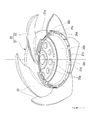
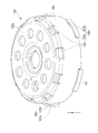
- FIG. 2 is a perspective view showing the impeller and the rotor cup of the first embodiment.
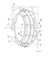
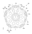
- FIG. 3 is a view of the rotor cup of the first embodiment as viewed from above.
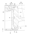
- FIG. 4 is a cross-sectional view showing a part of the impeller and a part of the rotor cup of the first embodiment.
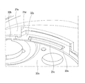
- FIG. 5 is a perspective view showing a part of the impeller and a part of the rotor cup according to the first embodiment.
- FIG. 6 is a perspective view showing a part of the impeller of the first embodiment.
- FIG. 7 is a perspective view showing an impeller and a rotor cup according to the second embodiment.
- FIG. 8 is a perspective view showing a rotor cup of the second embodiment.
- FIG. 9 is a top view of the rotor cup of the second embodiment.
- FIG. 10 is a cross-sectional view showing a part of the impeller and a part of the rotor cup of the second embodiment.
- FIG. 11 is a perspective view showing the impeller of the second embodiment.
- the Z-axis direction as shown in each figure is a vertical direction in which the positive side is the upper side and the negative side is the lower side.
- the vertical direction, the upper side, and the lower side are simply names for explaining the relative positional relationship of each part, and the actual layout relationship is a layout relationship other than the layout relationship indicated by these names. May be.
- the blower device 10 of the present embodiment includes a motor support portion 40, a motor 30 having a shaft 31 disposed along a central axis J extending in the vertical direction, the impeller 20, and a circuit board 80. And a housing 50.
- axial direction Z the direction parallel to the central axis J, that is, the vertical direction
- radial direction centered on the central axis J is simply referred to as “radial direction”
- circumferential direction centered on the central axis J is simply referred to as “circumferential direction”.
- the motor support unit 40 supports the motor 30.
- the motor support portion 40 includes a bottom plate portion 42 and a stator support portion 41.
- the bottom plate portion 42 has an annular plate shape centered on the central axis J.
- the stator support portion 41 has a cylindrical shape extending upward from the radially inner edge portion of the bottom plate portion 42.
- the stator support portion 41 opens on both sides in the axial direction Z. Two bearings arranged at an interval in the axial direction Z are fixed to the radially inner side surface of the stator support portion 41.
- the motor 30 includes a shaft 31, a stator 34, a rotor cup 32, and a rotor magnet 33.
- the shaft 31 is rotatably supported by two bearings fixed to the radially inner side surface of the stator support portion 41.
- the upper end portion of the shaft 31 protrudes above the stator support portion 41.
- a cylindrical attachment member 36 is fitted and fixed to the upper end portion of the shaft 31.
- the stator 34 surrounds the shaft 31 outside the shaft 31 in the radial direction.
- the stator 34 is, for example, an annular shape centering on the central axis J.
- the stator 34 is fixed to the radially outer surface of the stator support portion 41.
- the rotor cup 32 has a cylindrical shape that opens downward.
- the rotor cup 32 is made of metal, for example.
- the rotor cup 32 includes a first cylindrical portion 32b, a lid portion 32a, and a flange portion 32c.
- the first cylindrical portion 32b has a cylindrical shape extending in the axial direction Z with the central axis J as the center.
- the first cylindrical portion 32 b surrounds the stator 34 on the radially outer side of the stator 34.
- the lid portion 32a has an annular plate shape centered on the central axis J.
- the radially outer edge portion of the lid portion 32a is connected to the upper end portion of the first cylindrical portion 32b. That is, the lid portion 32a is located at the upper end portion of the first cylindrical portion 32b.
- the lid portion 32 a covers the upper side of the stator 34.
- the radially inner edge portion 32 f of the lid portion 32 a is fixed to the upper end portion of the shaft 31 via the attachment member 36. Thereby, the rotor cup 32 is fixed to the shaft 31.
- the radially outer edge portion of the lid portion 32a is an impeller support portion 32h that is recessed downward.
- the lid portion 32 a has a plurality of through holes 32 g that penetrate the lid portion 32 a in the axial direction Z.
- the flange part 32c protrudes radially outward from the lower part of the first cylindrical part 32b. More specifically, the flange portion 32c protrudes radially outward from the lower end portion of the first tubular portion 32b.
- the rotor cup 32 has a plurality of flange portions 32c. 2 and 3, the number of the flange portions 32c is, for example, five. The plurality of flange portions 32c are arranged at equal intervals over one circumference along the circumferential direction.
- the shape viewed from the upper side of the flange portion 32 c is a substantially trapezoidal shape whose circumferential dimension decreases from the radially inner side toward the radially outer side.
- the edge portions 32d on both sides in the circumferential direction of the flange portion 32c are inclined so as to approach the opposite edge portions 32d from the radially inner side toward the radially outer side.
- the edge portion 32d and the first portion at the punched portion The angle of the site
- circular shaped plate-shaped part can be made into an obtuse angle. Therefore, wear of the press die can be suppressed, and the life of the press die can be improved.
- the radially outer end of the flange portion 32 c is substantially in the same radial position as the radially outer surface of the second cylindrical portion 21 a described later in the impeller cup 21.
- An end portion on the radially outer side of the flange portion 32c is positioned slightly inward in the radial direction with respect to the radially outer surface of the second tubular portion 21a. Therefore, the flow of air flowing along the radially outer surface of the second cylindrical portion 21a is less likely to be inhibited compared to the case where the flange portion protrudes radially outward from the second cylindrical portion. Thereby, it can suppress that the air volume of the air blower 10 reduces, and the noise which arises from the air blower 10 can be reduced.
- the flange portion 32c has a first hole portion 35 that is recessed in the axial direction Z.
- the first hole portion 35 penetrates the flange portion 32 c in the axial direction Z.
- the first hole 35 extends in the circumferential direction.
- the 1st hole part 35 is located in the center of the radial direction in the flange part 32c. Therefore, the radial dimension L1 in the radially inner part of the first hole 35 in the flange part 32c and the radial dimension L2 in the radially outer part of the first hole 35 in the flange 32c are: Is almost the same. Thereby, it is easy to ensure the strength of the flange portion 32c. Further, when the first hole portion 35 is formed by punching a part of the flange portion 32c, the first hole portion 35 is easily formed.
- the first hole portion 35 is made, for example, by punching a part of the flange portion 32c with a press die. More specifically, in a state where the lower surface of the flange portion 32c is installed on the die, a punch is brought close to the upper side of the flange portion 32c, and a part of the flange portion 32c is punched out. Therefore, as shown in FIG. 5, for example, a burr 32e is generated at the peripheral edge portion of the first hole portion 35 on the lower surface of the flange portion 32c. That is, the rotor cup 32 has a burr 32e positioned at the peripheral edge of the first hole 35 on the lower surface of the flange portion 32c.
- the rotor magnet 33 is fixed to the radially inner side surface of the first cylindrical portion 32b. Thereby, the first cylindrical portion 32 b holds the rotor magnet 33.
- the rotor magnet 33 faces the stator 34 via a gap in the radial direction outside the stator 34 in the radial direction.
- the impeller 20 is rotated around the central axis J by the motor 30.
- the impeller 20 is made of resin, for example.
- the impeller 20 includes a plurality of blade portions 22 and an impeller cup 21. As shown in FIG. 2, the plurality of blade portions 22 are located on a radially outer side surface of a second cylindrical portion 21 a described later in the impeller cup 21.
- wing part 22 is arrange
- the blade portion 22 sends wind in the axial direction Z as the impeller 20 rotates.
- the impeller cup 21 has a cylindrical shape that opens on both sides in the axial direction Z.
- the impeller cup 21 is fitted into the rotor cup 32 from the radially outer side.
- the impeller cup 21 includes a second cylindrical portion 21a, a plurality of first ribs 23a and a plurality of second ribs 23b as a plurality of ribs, a contact portion 21b, and a first convex portion 21c. And having.
- the second tubular portion 21 a has a tubular shape surrounding the first tubular portion 32 b on the radially outer side of the rotor cup 32. More specifically, the second cylindrical portion 21a is cylindrical with the central axis J as the center. As shown in FIG. 6, the second tubular portion 21a has a first recess 21e that is recessed radially outward from the radially inner side surface of the second tubular portion 21a. In FIG. 6, the first recess 21e is a groove extending in an annular shape along the circumferential direction. The 1st recessed part 21e is located in the center of the axial direction Z in the radial direction inner surface of the 2nd cylindrical part 21a.
- the second cylindrical portion 21a has a plurality of second concave portions 21d that are recessed upward from the lower end portion of the second cylindrical portion 21a.
- the plurality of second recesses 21d are arranged at equal intervals over the entire circumference along the circumferential direction.
- the plurality of first ribs 23a and the plurality of second ribs 23b protrude radially inward from the radially inner side surface of the second cylindrical portion 21a.
- the 1st rib 23a is located in the part below the 1st recessed part 21e among the radial direction inner surfaces of the 2nd cylindrical part 21a.
- the 1st rib 23a is extended in the axial direction Z from the lower end part in the radial direction inner surface of the 2nd cylindrical part 21a to the lower edge part of the 1st recessed part 21e.
- the plurality of first ribs 23a are arranged at intervals from each other along the circumferential direction. More specifically, the plurality of first ribs 23a are arranged at equal intervals over the entire circumference in the circumferential direction.
- 2nd rib 23b is located in the part above the 1st recessed part 21e among the radial direction inner surfaces of the 2nd cylindrical part 21a.
- the second rib 23b extends in the axial direction Z from the upper end portion on the radially inner side surface of the second cylindrical portion 21a to the upper edge portion of the first recess 21e.
- the plurality of second ribs 23b are arranged at intervals from each other along the circumferential direction.
- the plurality of second ribs 23b are arranged at equal intervals over the entire circumference along the circumferential direction.
- the plurality of first ribs 23a and the plurality of second ribs 23b are respectively arranged at the same position in the circumferential direction.
- the plurality of first ribs 23a and the plurality of second ribs 23b are in contact with the radially outer surface of the first cylindrical portion 32b. That is, the impeller cup 21 is in contact with the radially outer surface of the rotor cup 32 via the plurality of first ribs 23a and the plurality of second ribs 23b. Thereby, the contact area of the impeller cup 21 and the radial direction outer surface of the rotor cup 32 can be made small. Therefore, for example, when the thermal expansion coefficient of the impeller cup 21 and the thermal expansion coefficient of the rotor cup 32 are different, the stress generated in the rotor cup 32 and the impeller cup 21 due to thermal expansion or thermal contraction can be reduced. Therefore, it can suppress that the impeller cup 21 and the rotor cup 32 are damaged.
- the thermal expansion coefficient of the impeller 20 is larger than the thermal expansion coefficient of the rotor cup 32.
- the amount of deformation due to the thermal contraction of the impeller cup 21 is larger than the amount of deformation due to the thermal contraction of the rotor cup 32. Even in this case, since the stress generated in the impeller cup 21 can be reduced as described above, the resin-made impeller cup 21 can be prevented from being damaged.
- the contact portion 21b protrudes radially inward from the upper portion of the second cylindrical portion 21a. More specifically, the contact portion 21b protrudes radially inward from the upper end portion of the second cylindrical portion 21a.
- the contact portion 21 b includes an annular portion 21 f and a plurality of third ribs 23 c.
- the annular portion 21f has an annular shape centered on the central axis J. The radially outer edge portion of the annular portion 21f is connected to the upper end portion of the second cylindrical portion 21a.
- the annular portion 21f is located above the impeller support portion 32h. An end portion on the radially inner side of the annular portion 21f faces the lid portion 32a in the radial direction with a gap therebetween.
- the third rib 23c protrudes downward from the lower surface of the annular portion 21f.
- the third rib 23c extends in the radial direction.
- the plurality of third ribs 23c are arranged at equal intervals over the entire circumference in the circumferential direction.
- the plurality of third ribs 23c and the plurality of second ribs 23b are respectively disposed at the same position in the circumferential direction.
- the radially outer end of the third rib 23c is connected to the upper end of the second rib 23b.
- the contact portion 21 b comes into contact with the rotor cup 32 on the upper side of the rotor cup 32. More specifically, the third rib 23c comes into contact with the upper surface of the impeller support portion 32h. That is, the impeller cup 21 is in contact with the upper surface of the rotor cup 32 through the plurality of third ribs 23c. Thereby, the contact area between the impeller cup 21 and the upper surface of the rotor cup 32 can be reduced. Therefore, for example, when the thermal expansion coefficient of the impeller cup 21 and the thermal expansion coefficient of the rotor cup 32 are different, the stress generated in the impeller cup 21 and the rotor cup 32 due to thermal expansion or thermal contraction can be further reduced. Therefore, it can suppress more that the impeller cup 21 and the rotor cup 32 are damaged.
- the second tubular portion 21a is disposed away from the flange portion 32c. That is, the flange portion 32c is arranged with a gap below the second cylindrical portion 21a. Therefore, the position of the impeller cup 21 in the axial direction Z can be accurately positioned with respect to the rotor cup 32 by bringing the contact portion 21b into contact with the impeller support portion 32h.
- the first convex portion 21c protrudes downward from the second cylindrical portion 21a. More specifically, as shown in FIG. 6, the inner surface of the second recess 21d protrudes downward from the surface facing downward.
- the lower end portion of the first convex portion 21c is at the same position in the axial direction Z as the lower end portion of the second tubular portion 21a, for example.
- the first convex portion 21c extends in the circumferential direction.
- the 1st convex part 21c is a rectangular plate shape curved in circular arc shape along the circumferential direction.
- the first convex portion 21 c is located in the first hole portion 35. Therefore, for example, even when centrifugal force or the like is applied to the impeller cup 21 and the impeller cup 21 is about to be deformed radially outward, the first convex portion 21c is caught on the inner surface of the first hole portion 35, The deformation of the impeller cup 21 can be suppressed. Thereby, it can suppress that the air volume characteristic of the air blower 10 falls. Moreover, it can suppress that the blade
- the 1st convex part 21c exists in the position away from the surface of the both radial direction among the inner surfaces of the 1st hole part 35 in the radial direction. From this state, when the impeller cup 21 is deformed radially outward, the first convex portion 21 c is brought into contact with and caught on the radially outer surface of the inner surface of the first hole portion 35. Thereby, it can suppress that the 1st convex part 21c moves to a radial direction outer side rather than the 1st hole part 35, and can suppress the deformation
- the flange part 32c has the 1st hole part 35, and the impeller cup 21 has the 1st convex part 21c. Therefore, compared with the case where the first hole portion is formed in the impeller cup 21, the first hole portion 35 can be easily formed by punching a part of the flange portion 32c.
- the first convex portion 21c is inserted into the first hole portion 35 from above.
- the first convex portion 21 c passes through the first hole portion 35 in the axial direction Z.
- the lower end part of the 1st convex part 21c is located below the flange part 32c. Therefore, it is easy to reliably hook the first convex portion 21c into the first hole portion 35, and the deformation of the impeller cup 21 can be further suppressed.
- a weight or the like for adjusting the balance of the center of gravity can be attached to the lower end portion of the first convex portion 21c.
- the burr 32e generated when the first hole portion 35 is punched out with a press die is provided on the lower surface of the flange portion 32c. Therefore, as compared with the case where the burr 32e is formed on the upper surface of the flange portion 32c, the burr 32e does not hinder the insertion of the first convex portion 21c, and the first convex portion 21c is inserted into the first hole portion 35 from above. Cheap.
- the impeller cup 21 has a plurality of first convex portions 21c. As shown in FIG. 6, each of the plurality of first protrusions 21 c protrudes downward from each of the inner surfaces of the plurality of second recesses 21 d facing downward.
- the plurality of first protrusions 21c are inserted into the plurality of first holes 35, respectively. Thereby, a deformation
- the number of first convex portions 21 c is the same as the number of blade portions 22. In FIG. 2, for example, the number of first convex portions 21c is five.
- the plurality of first convex portions 21c are arranged at equal intervals over the entire circumference in the circumferential direction.
- the portion of the second cylindrical portion 21a to which the blade portion 22 is connected is particularly easily deformed than the other portion of the second cylindrical portion 21a due to its own weight.
- at least a part of the first hole 35 and the first convex portion 21c overlaps a position in the circumferential direction with a portion of the second cylindrical portion 21a to which the blade portion 22 is connected. Therefore, the deformation of the portion that is particularly easily deformed in the second cylindrical portion 21a can be suitably suppressed, and the deformation of the impeller cup 21 can be further suppressed.
- the first hole portion 35 and the first convex portion 21c entirely overlap with the portion in the second cylindrical portion 21a to which the blade portion 22 is connected in the circumferential direction.
- the impeller cup 21 is fixed to the rotor cup 32 by an adhesive 70 in the present embodiment.
- the adhesive 70 is formed between the portion between the first ribs 23a adjacent in the circumferential direction on the radially inner side surface of the second tubular portion 21a and the radially outer surface of the first tubular portion 32b. It arrange
- the adhesive 70 that bonds the radially inner side surface of the second tubular portion 21a and the radially outer surface of the first tubular portion 32b is disposed in the first recess 21e. Therefore, the adhesive 70 disposed in the first recess 21e functions as a retaining stopper, and it is possible to suppress the impeller cup 21 from moving away from the rotor cup 32 in the axial direction Z.
- the circuit board 80 has a plate shape extending in the radial direction.
- the circuit board 80 is fixed to the stator 34 below the stator 34.
- the circuit board 80 is electrically connected to the motor 30.
- the housing 50 is disposed on the radially outer side than the motor support portion 40.
- the housing 50 has a cylindrical shape extending in the axial direction Z.
- the housing 50 surrounds the impeller 20 and the motor 30 on the radially outer side of the impeller 20 and the motor 30.
- the lower end portion of the housing 50 is connected to the motor support portion 40 by a plurality of connection ribs 51.
- the present invention is not limited to the above-described embodiment, and other configurations can be adopted.
- the same configurations as those in the above embodiment may be omitted by appropriately attaching the same reference numerals.
- the lid portion 132a of the rotor cup 132 has a second hole portion 132i that is recessed downward from the upper surface of the lid portion 132a.
- the 2nd hole 132i is located in the radial direction outer edge part of the cover part 132a.
- the second hole portion 132 i penetrates the lid portion 132 a in the axial direction Z.
- the second hole portion 132i extends from the radially outer edge portion of the lid portion 132a to the upper end portion of the first tubular portion 32b.
- the rotor cup 132 has, for example, a plurality of second holes 132i.
- the plurality of second hole portions 132i are arranged at equal intervals over the entire circumference along the circumferential direction.
- the number of second holes 132i is, for example, ten.
- the flange portion 132c includes a flange portion main body 137a and a first convex portion 137b. As shown in FIG. 8, the flange portion main body 137a protrudes radially outward from the lower portion of the first tubular portion 32b. More specifically, the flange portion main body 137a protrudes radially outward from the lower end portion of the first tubular portion 32b. As shown in FIG. 9, the circumferential dimension of the flange portion main body 137a increases from the radially inner side toward the radially outer side. Edge portions 132d on both sides in the circumferential direction of the flange portion main body 137a extend linearly along the radial direction.
- the first convex portion 137b protrudes upward from an end portion on the radially outer side of the flange portion main body 137a.
- the first convex portion 137b extends in the circumferential direction.
- the 1st convex part 137b is a rectangular plate shape curved in circular arc shape along the circumferential direction.
- the dimension of the 1st convex part 137b in the circumferential direction is the same as the dimension in the circumferential direction at the radially outer end of the flange part main body 137a.
- the second cylindrical portion 121a of the impeller cup 121 has a main body portion 121f, an inner cylindrical portion 121g, and an outer cylindrical portion 121h.
- the main body 121f has a cylindrical shape extending in the axial direction Z around the central axis J.
- the inner cylinder part 121g has a cylindrical shape extending downward from the radially inner edge part of the main body part 121f. The lower end part of the inner cylinder part 121g contacts the upper surface of the flange part main body 137a.
- the outer cylindrical portion 121h has a cylindrical shape extending downward from the radially outer edge portion of the main body portion 121f.
- the outer cylindrical portion 121h is disposed away from the radially outer side of the inner cylindrical portion 121g.
- the lower end part of the outer cylinder part 121h is located below the lower end part of the inner cylinder part 121g.
- the lower end part of the outer cylinder part 121h is located below the flange part 132c.
- the main body portion 121f, the inner cylindrical portion 121g, and the outer cylindrical portion 121h constitute a first hole portion 121i that is recessed upward from the lower end portion of the second cylindrical portion 121a. That is, the impeller cup 121 has a first hole 121i.
- the first hole 121i is a hole having a bottom. At least a part of the first protrusion 137b is located in the first hole 121i. Thereby, similarly to 1st Embodiment, it can suppress that the impeller cup 121 deform
- the impeller cup 121 has the first hole 121i, and the flange 132c has the first convex portion 137b. Therefore, for example, the radial dimension of the flange portion 132c can be easily reduced as compared with a case where the first hole portion is formed in the flange portion. Thereby, it is easy to make the dimension of the air blower 110 in the radial direction small.
- the entire first convex portion 137b is located in the first hole portion 121i.
- the 1st convex part 137b is located between the inner cylinder part 121g and the radial direction of the outer cylinder part 121h. In FIG. 10, the 1st convex part 137b exists in the position away from the inner side cylinder part 121g and the outer side cylinder part 121h in radial direction.
- the edge part of the radial direction outer side of the flange part 132c is 1st seeing from the upper side. It can arrange
- the upper end of the first protrusion 137b is disposed away from the bottom of the first hole 121i.
- the impeller cup 121 has a second convex portion 124.
- the second convex portion 124 has a quadrangular prism shape that protrudes downward from the contact portion 121b.
- at least a part of the second convex portion 124 is located in the second hole portion 132i. Therefore, even when the impeller cup 121 is about to deform outward in the radial direction, the second convex portion 124 is caught on the inner surface of the second hole portion 132i, and the deformation of the impeller cup 121 is further suppressed. Further, the impeller cup 121 can be further suppressed from rotating in the circumferential direction with respect to the rotor cup 132.
- the contact portion 121b does not have a third rib.
- the impeller cup 121 has a plurality of second convex portions 124.
- the plurality of second convex portions 124 are arranged at equal intervals over the entire circumference along the circumferential direction.
- Each of the plurality of second protrusions 124 is inserted into each of the plurality of second holes 132i. Thereby, a deformation
- the impeller cup 121 has a plurality of ribs 123 that protrude radially inward from the radially inner side surface of the second cylindrical portion 121a.
- the some rib 123 is arrange
- the plurality of ribs 123 are at the same position in the circumferential direction as the plurality of second convex portions 124.
- the rib 123 extends in the axial direction Z from the lower end portion of the radially inner side surface of the inner cylindrical portion 121g to the upper end portion of the radially inner side surface of the main body portion 121f.
- the plurality of ribs 123 are in contact with the outer peripheral surface of the first cylindrical portion 32b.
- the radially outer end of the flange portion may be at the same position in the radial direction as the radially outer surface of the second tubular portion. Even in this case, since the end portion on the radially outer side of the flange portion does not protrude radially outward than the second tubular portion, it is possible to suppress a reduction in the air volume of the blower and to reduce noise generated from the blower. . Moreover, the edge part of the radial direction outer side of a flange part may be located in the radial direction outer side rather than the radial direction outer surface of a 2nd cylindrical part. Moreover, if a flange part is a lower part of a 1st cylindrical part, you may protrude in the radial direction outer side from the part above a lower end part of a 1st cylindrical part.
- the first hole may be a hole having a bottom.
- the first hole portion may be a hole that penetrates the second tubular portion in the axial direction Z.
- one of the flange portion and the impeller cup has the first hole portion, and the other of the flange portion and the impeller cup has the first convex portion.
- both the flange portion and the impeller cup may each have a first hole portion and a first convex portion.
- the shape of a 1st convex part and the shape of a 1st hole part are not specifically limited.
- the rotor cup may not have burrs.
- stator 35, 121i ... first hole part, 70 ... adhesive, 123 ... rib, 124 ... 2nd convex part, 132i ... 2nd hole part, 137a ... Flange part main body, J ... Central axis, Z ... Axial direction
Landscapes
- Engineering & Computer Science (AREA)
- Mechanical Engineering (AREA)
- General Engineering & Computer Science (AREA)
- Power Engineering (AREA)
- Structures Of Non-Positive Displacement Pumps (AREA)
- Connection Of Motors, Electrical Generators, Mechanical Devices, And The Like (AREA)
Abstract
Selon un mode de réalisation, l'invention concerne un dispositif de soufflage pourvu d'un moteur et d'une turbine qui est mise en rotation autour de l'axe central par le moteur. Le moteur comprend : un stator radialement à l'extérieur de l'arbre et entourant un arbre ; un aimant de rotor radialement à l'extérieur du stator et faisant face au stator avec un espace radial interposé entre eux ; et un capuchon de rotor ayant une première partie tubulaire tubulaire destinée à maintenir l'aimant de rotor. La turbine comprend : un capuchon de turbine ayant une seconde unité tubulaire tubulaire entourant la première unité tubulaire radialement à l'extérieur du capuchon de rotor ; et plusieurs pales positionnées sur la surface radialement externe de la seconde unité tubulaire. Le capuchon de rotor comporte une bride qui fait saillie radialement vers l'extérieur à partir de la partie inférieure de la première unité tubulaire. La bride ou le capuchon de turbine comporte une première partie trou qui est évidée dans la direction axiale. L'autre de la bride et du capuchon de turbine comporte une première saillie positionnée au moins partiellement à l'intérieur de la première partie trou.
Priority Applications (3)
| Application Number | Priority Date | Filing Date | Title |
|---|---|---|---|
| JP2018524186A JPWO2017222055A1 (ja) | 2016-06-24 | 2017-06-23 | 送風装置 |
| CN201780038337.3A CN109477493B (zh) | 2016-06-24 | 2017-06-23 | 送风装置 |
| US16/311,233 US20190186495A1 (en) | 2016-06-24 | 2017-06-23 | Blower |
Applications Claiming Priority (2)
| Application Number | Priority Date | Filing Date | Title |
|---|---|---|---|
| US201662354190P | 2016-06-24 | 2016-06-24 | |
| US62/354190 | 2016-06-24 |
Publications (1)
| Publication Number | Publication Date |
|---|---|
| WO2017222055A1 true WO2017222055A1 (fr) | 2017-12-28 |
Family
ID=60783871
Family Applications (1)
| Application Number | Title | Priority Date | Filing Date |
|---|---|---|---|
| PCT/JP2017/023247 Ceased WO2017222055A1 (fr) | 2016-06-24 | 2017-06-23 | Dispositif de soufflage |
Country Status (4)
| Country | Link |
|---|---|
| US (1) | US20190186495A1 (fr) |
| JP (1) | JPWO2017222055A1 (fr) |
| CN (1) | CN109477493B (fr) |
| WO (1) | WO2017222055A1 (fr) |
Cited By (1)
| Publication number | Priority date | Publication date | Assignee | Title |
|---|---|---|---|---|
| JP2024048818A (ja) * | 2022-09-28 | 2024-04-09 | ニデックアドバンスドモータ株式会社 | 送風機および遠心ファン |
Citations (3)
| Publication number | Priority date | Publication date | Assignee | Title |
|---|---|---|---|---|
| JP2003254292A (ja) * | 2002-03-04 | 2003-09-10 | Nippon Densan Corp | ファン |
| US20040126232A1 (en) * | 2002-12-30 | 2004-07-01 | Kuo-Cheng Lin | Rotor assembly |
| DE202014104711U1 (de) * | 2014-10-01 | 2014-10-20 | Asia Vital Components Co., Ltd. | Auswuchtstruktur der Radnabe eines Ventilators |
Family Cites Families (40)
| Publication number | Priority date | Publication date | Assignee | Title |
|---|---|---|---|---|
| BE763443A (fr) * | 1970-03-12 | 1971-07-16 | Ryba Anton | Ventilateur, en particulier pour systemes de refroidissement sur les vehicules automobiles |
| TW551430U (en) * | 2000-04-08 | 2003-09-01 | Delta Electronics Inc | Crack preventing structure for fan |
| JP2002039096A (ja) * | 2000-07-27 | 2002-02-06 | Minebea Co Ltd | 送風機 |
| US20040075356A1 (en) * | 2002-10-16 | 2004-04-22 | Sunonwealth Electric Machine Industry Co., Ltd. | Fan rotor |
| TWM243848U (en) * | 2003-07-09 | 2004-09-11 | Sunonwealth Electr Mach Ind Co | Rotational balance structure for a motor |
| US20060039789A1 (en) * | 2004-08-20 | 2006-02-23 | Datech Technology Co., Ltd. | Hub structure for a heat-dissipation fan |
| US7034417B1 (en) * | 2004-12-20 | 2006-04-25 | Asia Vital Component Co., Ltd. | Rotor assembly capable of dissipating heat |
| TWI296025B (en) * | 2005-05-27 | 2008-04-21 | Delta Electronics Inc | Fan and impeller thereof |
| JP4857631B2 (ja) * | 2005-07-15 | 2012-01-18 | 日本電産株式会社 | ファンモータ |
| TWI322228B (en) * | 2007-03-06 | 2010-03-21 | Delta Electronics Inc | Fan |
| JP5286689B2 (ja) * | 2007-04-17 | 2013-09-11 | 日本電産株式会社 | 冷却ファンユニット |
| CN101684822A (zh) * | 2008-09-26 | 2010-03-31 | 富准精密工业(深圳)有限公司 | 散热风扇及其转子 |
| JP5206482B2 (ja) * | 2009-02-24 | 2013-06-12 | 日本電産株式会社 | 送風機用インペラおよび送風機 |
| DE102009003142A1 (de) * | 2009-05-15 | 2010-11-18 | Robert Bosch Gmbh | Lüfter-Rotor-Verbindung für ein Kühlgebläse eines Kraftfahrzeugs |
| JP5519196B2 (ja) * | 2009-06-24 | 2014-06-11 | サムスン電機ジャパンアドバンスドテクノロジー株式会社 | ディスク駆動装置 |
| JP5636788B2 (ja) * | 2009-08-03 | 2014-12-10 | 日本電産株式会社 | 送風ファン |
| JP5079035B2 (ja) * | 2010-02-15 | 2012-11-21 | 日本電産サーボ株式会社 | インペラ及び送風ファン |
| US8690552B2 (en) * | 2010-11-15 | 2014-04-08 | Forcecon Technology Co., Ltd. | Compact and strengthened rotor assembly of a radiator fan |
| CN102808801A (zh) * | 2011-05-31 | 2012-12-05 | 富准精密工业(深圳)有限公司 | 散热风扇 |
| CN202301212U (zh) * | 2011-08-26 | 2012-07-04 | 日本电产株式会社 | 风扇马达 |
| CN102954044B (zh) * | 2011-08-26 | 2016-01-20 | 日本电产株式会社 | 风扇马达 |
| DE102011089092A1 (de) * | 2011-12-19 | 2013-06-20 | Behr Gmbh & Co. Kg | Gehäuse insbesondere für eine Kraftfahrzeugklimaanlage |
| JP5945912B2 (ja) * | 2012-02-09 | 2016-07-05 | 日本電産株式会社 | ファン |
| FR2988337B1 (fr) * | 2012-03-22 | 2015-05-08 | Valeo Systemes Thermiques | Systeme de ventilation |
| US20130266463A1 (en) * | 2012-04-04 | 2013-10-10 | Alphana Technology Co., Ltd. | Fan motor |
| TWI607154B (zh) * | 2012-05-21 | 2017-12-01 | 鴻準精密工業股份有限公司 | 扇葉 |
| JP6228728B2 (ja) * | 2012-05-29 | 2017-11-08 | ミネベアミツミ株式会社 | 遠心送風ファン |
| TWI526621B (zh) * | 2012-09-18 | 2016-03-21 | 台達電子工業股份有限公司 | 風扇 |
| TWI546455B (zh) * | 2012-12-13 | 2016-08-21 | 鴻準精密工業股份有限公司 | 磁框、轉子及風扇 |
| US9636779B2 (en) * | 2013-05-28 | 2017-05-02 | Asia Vital Components Co., Ltd. | Connection structure applied to a fan for connecting a metal member with a shaft by means of laser |
| TWI537476B (zh) * | 2013-07-15 | 2016-06-11 | Sunon Electronics Foshan Co Ltd | Axial fan |
| JP5839755B1 (ja) * | 2015-01-08 | 2016-01-06 | 山洋電気株式会社 | ファンケーシング及びファン装置 |
| JP5775981B1 (ja) * | 2015-03-31 | 2015-09-09 | 山洋電気株式会社 | ファン装置 |
| DE102015222005A1 (de) * | 2015-11-09 | 2017-05-11 | Mahle International Gmbh | Fördereinrichtung |
| JP6419748B2 (ja) * | 2016-04-05 | 2018-11-07 | ミネベアミツミ株式会社 | 遠心ファン |
| JP2018061408A (ja) * | 2016-10-07 | 2018-04-12 | 日本電産株式会社 | ファンモータ |
| JP2018178802A (ja) * | 2017-04-07 | 2018-11-15 | 日本電産株式会社 | ファンモータ |
| JP7031290B2 (ja) * | 2017-12-22 | 2022-03-08 | 日本電産株式会社 | 送風機 |
| JP2019120151A (ja) * | 2017-12-28 | 2019-07-22 | 日本電産株式会社 | ファン |
| JP7105584B2 (ja) * | 2018-03-13 | 2022-07-25 | 山洋電気株式会社 | ファンモータ装置およびファンモータ装置の保護カバー |
-
2017
- 2017-06-23 WO PCT/JP2017/023247 patent/WO2017222055A1/fr not_active Ceased
- 2017-06-23 US US16/311,233 patent/US20190186495A1/en not_active Abandoned
- 2017-06-23 CN CN201780038337.3A patent/CN109477493B/zh active Active
- 2017-06-23 JP JP2018524186A patent/JPWO2017222055A1/ja active Pending
Patent Citations (3)
| Publication number | Priority date | Publication date | Assignee | Title |
|---|---|---|---|---|
| JP2003254292A (ja) * | 2002-03-04 | 2003-09-10 | Nippon Densan Corp | ファン |
| US20040126232A1 (en) * | 2002-12-30 | 2004-07-01 | Kuo-Cheng Lin | Rotor assembly |
| DE202014104711U1 (de) * | 2014-10-01 | 2014-10-20 | Asia Vital Components Co., Ltd. | Auswuchtstruktur der Radnabe eines Ventilators |
Cited By (1)
| Publication number | Priority date | Publication date | Assignee | Title |
|---|---|---|---|---|
| JP2024048818A (ja) * | 2022-09-28 | 2024-04-09 | ニデックアドバンスドモータ株式会社 | 送風機および遠心ファン |
Also Published As
| Publication number | Publication date |
|---|---|
| CN109477493A (zh) | 2019-03-15 |
| CN109477493B (zh) | 2021-06-15 |
| JPWO2017222055A1 (ja) | 2019-05-16 |
| US20190186495A1 (en) | 2019-06-20 |
Similar Documents
| Publication | Publication Date | Title |
|---|---|---|
| US9062567B2 (en) | Fan | |
| JP5892375B2 (ja) | 動圧軸受装置およびファン | |
| US10594186B2 (en) | Outer rotor type motor | |
| CN109958629B (zh) | 送风机 | |
| US9670932B2 (en) | Fan | |
| US20130004304A1 (en) | Fan | |
| JP2005027431A (ja) | モータ | |
| CN104728133B (zh) | 风扇 | |
| US20200271117A1 (en) | Axial fan | |
| US20090256441A1 (en) | Motor structure | |
| JP2010057300A (ja) | モータ及びファン | |
| US8143761B2 (en) | Motor assembly | |
| JP4816479B2 (ja) | モータ | |
| CN109477493B (zh) | 送风装置 | |
| US9047910B2 (en) | Spindle motor and hard disk drive including the same | |
| JP5198083B2 (ja) | ブラシレスモータ | |
| JP2008283750A (ja) | 油圧ダンパ用モータ | |
| CN210129790U (zh) | 马达 | |
| CN113541378A (zh) | 电机 | |
| CN110323900B (zh) | 马达以及送风装置 | |
| US12088148B2 (en) | Housing for an electric motor | |
| CN112840533B (zh) | 风扇马达防水构造 | |
| JP2019054614A (ja) | モータ | |
| US20150214808A1 (en) | Spindle motor and hard disk drive including the same | |
| JP2015017547A (ja) | ハブ及び送風機 |
Legal Events
| Date | Code | Title | Description |
|---|---|---|---|
| 121 | Ep: the epo has been informed by wipo that ep was designated in this application |
Ref document number: 17815520 Country of ref document: EP Kind code of ref document: A1 |
|
| NENP | Non-entry into the national phase |
Ref country code: DE |
|
| ENP | Entry into the national phase |
Ref document number: 2018524186 Country of ref document: JP Kind code of ref document: A |
|
| 122 | Ep: pct application non-entry in european phase |
Ref document number: 17815520 Country of ref document: EP Kind code of ref document: A1 |