WO2018003091A1 - 熱交換器およびそれを備えた冷凍サイクル装置 - Google Patents
熱交換器およびそれを備えた冷凍サイクル装置 Download PDFInfo
- Publication number
- WO2018003091A1 WO2018003091A1 PCT/JP2016/069530 JP2016069530W WO2018003091A1 WO 2018003091 A1 WO2018003091 A1 WO 2018003091A1 JP 2016069530 W JP2016069530 W JP 2016069530W WO 2018003091 A1 WO2018003091 A1 WO 2018003091A1
- Authority
- WO
- WIPO (PCT)
- Prior art keywords
- heat exchanger
- wall
- heat transfer
- wall upper
- fin
- Prior art date
- Legal status (The legal status is an assumption and is not a legal conclusion. Google has not performed a legal analysis and makes no representation as to the accuracy of the status listed.)
- Ceased
Links
Images


Classifications
-
- F—MECHANICAL ENGINEERING; LIGHTING; HEATING; WEAPONS; BLASTING
- F28—HEAT EXCHANGE IN GENERAL
- F28F—DETAILS OF HEAT-EXCHANGE AND HEAT-TRANSFER APPARATUS, OF GENERAL APPLICATION
- F28F1/00—Tubular elements; Assemblies of tubular elements
- F28F1/02—Tubular elements of cross-section which is non-circular
-
- F—MECHANICAL ENGINEERING; LIGHTING; HEATING; WEAPONS; BLASTING
- F25—REFRIGERATION OR COOLING; COMBINED HEATING AND REFRIGERATION SYSTEMS; HEAT PUMP SYSTEMS; MANUFACTURE OR STORAGE OF ICE; LIQUEFACTION SOLIDIFICATION OF GASES
- F25B—REFRIGERATION MACHINES, PLANTS OR SYSTEMS; COMBINED HEATING AND REFRIGERATION SYSTEMS; HEAT PUMP SYSTEMS
- F25B39/00—Evaporators; Condensers
- F25B39/02—Evaporators
-
- F—MECHANICAL ENGINEERING; LIGHTING; HEATING; WEAPONS; BLASTING
- F28—HEAT EXCHANGE IN GENERAL
- F28F—DETAILS OF HEAT-EXCHANGE AND HEAT-TRANSFER APPARATUS, OF GENERAL APPLICATION
- F28F1/00—Tubular elements; Assemblies of tubular elements
- F28F1/02—Tubular elements of cross-section which is non-circular
- F28F1/022—Tubular elements of cross-section which is non-circular with multiple channels
-
- F—MECHANICAL ENGINEERING; LIGHTING; HEATING; WEAPONS; BLASTING
- F28—HEAT EXCHANGE IN GENERAL
- F28F—DETAILS OF HEAT-EXCHANGE AND HEAT-TRANSFER APPARATUS, OF GENERAL APPLICATION
- F28F1/00—Tubular elements; Assemblies of tubular elements
- F28F1/02—Tubular elements of cross-section which is non-circular
- F28F1/04—Tubular elements of cross-section which is non-circular polygonal, e.g. rectangular
-
- F—MECHANICAL ENGINEERING; LIGHTING; HEATING; WEAPONS; BLASTING
- F28—HEAT EXCHANGE IN GENERAL
- F28F—DETAILS OF HEAT-EXCHANGE AND HEAT-TRANSFER APPARATUS, OF GENERAL APPLICATION
- F28F1/00—Tubular elements; Assemblies of tubular elements
- F28F1/10—Tubular elements and assemblies thereof with means for increasing heat-transfer area, e.g. with fins, with projections, with recesses
- F28F1/12—Tubular elements and assemblies thereof with means for increasing heat-transfer area, e.g. with fins, with projections, with recesses the means being only outside the tubular element
- F28F1/24—Tubular elements and assemblies thereof with means for increasing heat-transfer area, e.g. with fins, with projections, with recesses the means being only outside the tubular element and extending transversely
- F28F1/32—Tubular elements and assemblies thereof with means for increasing heat-transfer area, e.g. with fins, with projections, with recesses the means being only outside the tubular element and extending transversely the means having portions engaging further tubular elements
-
- F—MECHANICAL ENGINEERING; LIGHTING; HEATING; WEAPONS; BLASTING
- F28—HEAT EXCHANGE IN GENERAL
- F28F—DETAILS OF HEAT-EXCHANGE AND HEAT-TRANSFER APPARATUS, OF GENERAL APPLICATION
- F28F13/00—Arrangements for modifying heat-transfer, e.g. increasing, decreasing
- F28F13/06—Arrangements for modifying heat-transfer, e.g. increasing, decreasing by affecting the pattern of flow of the heat-exchange media
- F28F13/08—Arrangements for modifying heat-transfer, e.g. increasing, decreasing by affecting the pattern of flow of the heat-exchange media by varying the cross-section of the flow channels
-
- F—MECHANICAL ENGINEERING; LIGHTING; HEATING; WEAPONS; BLASTING
- F28—HEAT EXCHANGE IN GENERAL
- F28F—DETAILS OF HEAT-EXCHANGE AND HEAT-TRANSFER APPARATUS, OF GENERAL APPLICATION
- F28F17/00—Removing ice or water from heat-exchange apparatus
- F28F17/005—Means for draining condensates from heat exchangers, e.g. from evaporators
-
- F—MECHANICAL ENGINEERING; LIGHTING; HEATING; WEAPONS; BLASTING
- F28—HEAT EXCHANGE IN GENERAL
- F28D—HEAT-EXCHANGE APPARATUS, NOT PROVIDED FOR IN ANOTHER SUBCLASS, IN WHICH THE HEAT-EXCHANGE MEDIA DO NOT COME INTO DIRECT CONTACT
- F28D21/00—Heat-exchange apparatus not covered by any of the groups F28D1/00 - F28D20/00
- F28D2021/0019—Other heat exchangers for particular applications; Heat exchange systems not otherwise provided for
- F28D2021/0068—Other heat exchangers for particular applications; Heat exchange systems not otherwise provided for for refrigerant cycles
- F28D2021/0071—Evaporators
-
- F—MECHANICAL ENGINEERING; LIGHTING; HEATING; WEAPONS; BLASTING
- F28—HEAT EXCHANGE IN GENERAL
- F28F—DETAILS OF HEAT-EXCHANGE AND HEAT-TRANSFER APPARATUS, OF GENERAL APPLICATION
- F28F2250/00—Arrangements for modifying the flow of the heat exchange media, e.g. flow guiding means; Particular flow patterns
- F28F2250/02—Streamline-shaped elements
Definitions
- the present invention relates to a heat exchanger and a refrigeration cycle apparatus including the heat exchanger, and more particularly to a heat exchanger including a fin-and-tube heat exchanger and a refrigeration cycle apparatus including the heat exchanger. .
- fin-and-tube heat exchangers are known as heat exchangers for air conditioners.
- a heat transfer tube is disposed so as to penetrate a plurality of plate-like fins.
- the heat transfer tube for example, a flat tube having a flat cross-sectional shape is used. Heat exchange is performed between a heat exchange fluid such as air that flows between the fins and a heat exchange fluid such as a refrigerant that flows through the heat transfer tubes.
- the heat exchanger using a flat tube can ensure a large heat transfer area in the heat transfer tube compared to a heat exchanger using a circular tube.
- the ventilation resistance of the heat exchange fluid can be suppressed. For this reason, heat transfer performance can be improved.
- a heat exchanger to which a flat tube is applied functions as an evaporator
- the drainage performance is inferior to that of a heat exchanger to which a circular tube is applied. That is, due to the cross-sectional shape of the heat transfer tube, water droplets tend to remain on the outer wall surface of the flat tube.
- the outdoor heat exchanger functions as an evaporator during heating operation.
- frost moisture contained in the air as the heat exchange fluid is condensed on the surface of the outdoor heat exchanger and is attached as frost.
- frost adheres between fins
- the ventilation resistance of air passing through the outdoor heat exchanger increases.
- frost adheres to the outdoor heat exchanger heat exchange between air and the refrigerant is not efficiently performed, and heat transfer performance is deteriorated.
- heat exchangers can be damaged by the growth of frost.
- the air conditioner is provided with a defrosting mode for removing frost attached to the outdoor heat exchanger as an operation mode.
- a defrosting mode for removing frost attached to the outdoor heat exchanger as an operation mode.
- water droplets may remain even when the operation is performed in the defrost mode. In such a case, the remaining water droplets solidify again and grow into larger frost. In order to avoid this, it is necessary to lengthen the operation time in the defrost mode. As a result, the temperature of the heated room is lowered, the comfort of the room is deteriorated, and the average heating capacity is lowered.
- Patent Document 1 proposes a heat exchanger in which a notch is provided on the downstream side of the fin air flow, and a flat tube is inserted into the notch so as to be inclined upward with respect to the air flow. Yes.
- the present invention has been made as part of such development, and one object is to provide a heat exchanger that can improve drainage, and the other object is such heat exchange. It is providing the refrigeration cycle apparatus provided with the vessel.
- the heat exchanger according to the present invention includes a plate-like fin having a width and a heat transfer tube.
- the heat transfer tubes are arranged so as to penetrate the fins.
- the fin has a first end and a second end facing each other across a width.
- the first region, the second region, and the third region are located in the width direction of the fin.
- a heat transfer tube is disposed in the first region.
- the second region is disposed closer to the first end than the first region.
- the third region is disposed closer to the second end than the first region.
- the heat transfer tube includes an outer wall lower surface, a first outer wall upper surface, and a second outer wall upper surface. The lower surface of the outer wall is located along the width direction.
- the upper surface of the first outer wall is connected to the lower surface of the outer wall, and is inclined in a manner away from the lower surface of the outer wall from the first end side toward the second end side.
- the upper surface of the second outer wall is connected to the upper surface of the first outer wall, and is inclined and connected to the lower surface of the outer wall from the upper surface of the first outer wall toward the second end side in a manner approaching the lower surface of the outer wall.
- the first inclination angle at which the first outer wall upper surface is inclined with respect to the outer wall lower surface is smaller than the second inclination angle at which the second outer wall upper surface is inclined with respect to the outer wall lower surface.
- the second region is provided on the first end side of the fin, and the third region is provided on the second end side.
- the heat transfer tube includes a first outer wall upper surface and a second outer wall upper surface that are inclined with respect to the outer wall lower surface.
- FIG. 1 It is a figure which shows the refrigerant circuit of the refrigerating-cycle apparatus provided with the outdoor heat exchanger based on each embodiment.
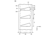
- It is a side view of the outdoor heat exchanger which concerns on Embodiment 1.
- it is a front view of an outdoor heat exchanger.
- it is a partial expanded sectional perspective view for demonstrating the structure of the heat exchanger tube applied to the outdoor heat exchanger.
- it is a partial enlarged side view for demonstrating the structure of the fin currently applied to the outdoor heat exchanger.
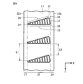
- it is a partial enlarged side view showing a state where a heat transfer tube is mounted on a fin.
- FIG. 1 shows the flow of the refrigerant
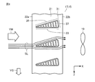
- it is a partial enlarged side view for explaining the flow of outside air passing through the outdoor heat exchanger.
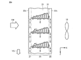
- it is a partial enlarged side view for demonstrating the flow of the water droplet which arose in the outdoor heat exchanger.
- it is a figure which shows the relationship between the residual water amount in a heat exchanger tube etc., and the inclination angle of the 1st outer wall upper surface of a heat exchanger tube. It is a side view of the outdoor heat exchanger which concerns on Embodiment 2.
- FIG. 1 shows the flow of the refrigerant
- it is a partial enlarged side view for explaining the flow of outside air passing through the outdoor heat exchanger.
- it is a partial enlarged side view for demonstrating the flow of the water
- it is a partial enlarged side view showing a state where a heat transfer tube is mounted on a fin.
- it is a partial enlarged side view for explaining the flow of outside air passing through the outdoor heat exchanger.
- it is a partial enlarged side view for demonstrating the flow of the water droplet which arose in the outdoor heat exchanger.
- Embodiment 1 An overall configuration (refrigerant circuit) of an air conditioner as a refrigeration cycle apparatus to which a heat exchanger is applied will be described.
- the air conditioner 1 includes a compressor 3, a four-way valve 5, an indoor unit 7, an indoor heat exchanger 9, an indoor fan 11, a throttling device 13, an outdoor unit 15, an outdoor heat exchanger 17, and an outdoor unit.
- a fan 19 is provided.
- the indoor heat exchanger 9 and the indoor fan 11 are arranged in the indoor unit 7.
- the outdoor heat exchanger 17 and the outdoor fan 19 are disposed in the outdoor unit 15.
- the compressor 3, the four-way valve 5, the indoor heat exchanger 9, the expansion device 13, and the outdoor heat exchanger 17 are connected by refrigerant piping.
- the outdoor heat exchanger 17 disposed in the outdoor unit 15 will be described.
- the outdoor heat exchanger 17 includes a plurality of fins 21 and a plurality of heat transfer tubes 31.
- the plurality of heat transfer tubes 31 are arranged so as to penetrate the plurality of fins 21.
- the plurality of fins 21 are arranged so that the longitudinal direction of the fins 21 is parallel to the gravity direction YG.
- An outdoor fan 19 is disposed so as to face the outdoor heat exchanger 17.
- the heat transfer tube 31 has a cross-sectional shape in which the length (width) in the X direction is longer than the length (width) in the Z direction.
- a plurality of flow paths 39 are provided in the heat transfer tubes 31 as flow paths through which the refrigerant flows.
- the heat transfer tube 31 is made of, for example, aluminum or an aluminum alloy.
- the heat transfer tube 31 may be formed by, for example, forming aluminum or the like so as to have an elliptical cross-sectional shape by extrusion molding, and further processing so as to obtain a final cross-sectional shape.
- the heat transfer tube 31 may have a groove formed on the inner wall surface.
- the heat transfer tube 31 includes an outer wall lower surface 33, a first outer wall upper surface 35, and a second outer wall upper surface 37.
- the first outer wall upper surface 35 is connected to the outer wall lower surface.
- the first outer wall upper surface 35 is inclined at a first inclination angle ⁇ 1 with respect to the outer wall lower surface 33, and an end 34 where the outer wall lower surface 33 and the first outer wall upper surface 35 are connected is rounded, and the outer wall lower surface 35 33 and the first outer wall upper surface 35 are smoothly connected.
- the second outer wall upper surface 37 is connected to the first outer wall upper surface 35 and the outer wall lower surface 33.
- the second outer wall upper surface 37 is inclined with respect to the outer wall lower surface 33 with a second inclination angle ⁇ 2.
- the end 36 where the first outer wall upper surface 35 and the second outer wall upper surface 37 are connected is rounded, and the first outer wall upper surface 35 and the second outer wall upper surface 37 are connected smoothly.
- the end 38 where the second outer wall upper surface 37 and the outer wall lower surface 33 are connected is rounded, and the second outer wall upper surface 37 and the outer wall lower surface 33 are connected smoothly.
- the roundness (R) of the end portion 34 is smaller than the roundness (R) of the end portions 36 and 38.
- the roundness (R) of the end portion 36 and the roundness (R) of the end portion 38 are substantially the same.
- the cross-sectional shape (contour) of the heat transfer tube 31 is formed substantially symmetrically with respect to the bisector of the first inclination angle ⁇ 1 at the end portion 34.
- the fin 21 has a width in the X direction and extends in a band shape in the Z direction with the width.
- the fins 21 are made of, for example, aluminum or an aluminum alloy.
- the fins 21 are formed with through holes 23 through which the heat transfer tubes are inserted.
- the through hole 23 is formed in a shape corresponding to the cross-sectional shape (contour) of the heat transfer tube 31.
- the end of the fin 21 that comes into contact with the outer wall lower surface 33 of the heat transfer tube 31 extends in the X direction.
- the corner portions 23 a, 23 b, and 23 c of the through hole 23 are rounded corresponding to the end portions 34, 36, and 38 of the heat transfer tube 31.
- the through holes 23 are formed with a pitch D.
- the corner 23 a of the through hole 23 is separated from the one end 22 a (first end) in the width direction of the fin 21 by a distance (length A).
- the corner 23b of the through hole 23 is separated from the other end 22b (second end) in the width direction of the fin 21 by a distance (length B).
- the through hole 23 is not located in the region from the end 22 a of the fin 21 to the length A.
- the portion of the plate-like fin 21 is positioned so as to be continuous along the Z direction.
- the through hole 23 is not located in the region from the end 22 b of the fin 21 to the length B.
- the plate-like fins 21 are positioned so as to be continuous along the Z direction.
- the portion of the plate-like fins 21 that is continuously located on the end 22a side is the first drainage region 27 (second region).
- the portion of the plate-like fin 21 that is continuously located on the end 22b side becomes the second drainage region 29 (third region).
- the first drainage area 27 and the second drainage area 29 are areas for draining water droplets (condensation) generated in the outdoor heat exchanger 17.
- region) through which the heat exchanger tube 31 is penetrated is located between the 1st drainage area 27 and the 2nd drainage area 29, the penetration area
- the outer wall lower surface 33 of the heat transfer tube 31 is positioned in parallel to the width direction (X direction) of the fins 21. That is, the outer wall lower surface 33 is positioned substantially horizontally.
- the upper surface 35 of the first outer wall 31 of the heat transfer tube 31 is inclined downward from the end 36 toward the first drainage region 27 with a first inclination angle ⁇ 1.
- the second outer wall upper surface 37 of the heat transfer tube 31 is downwardly inclined from the end portion 36 toward the second drainage region 29 with a second inclination angle ⁇ 2.
- the end portion 36 of the heat transfer tube 31 is located closer to the second drainage region 29 than the center of the fin 21 in the width direction.
- a distance L2 between the outer wall lower surface 33 of the one heat transfer tube 31 and the end portion 36 of the other heat transfer tube 31 Is shorter than the distance L1 between the end 34 of one heat transfer tube 31 and the end 34 of the other heat transfer tube 31.
- the high-pressure liquid refrigerant sent out from the outdoor heat exchanger 17 becomes a two-phase refrigerant consisting of a low-pressure gas refrigerant and a liquid refrigerant by the expansion device 13.
- the refrigerant in the two-phase state flows into the indoor heat exchanger 9 of the indoor unit 7.
- the indoor heat exchanger 9 heat exchange is performed between the flowing refrigerant in the two-phase state and the air supplied by the indoor fan 11.
- the liquid refrigerant evaporates to become a low-pressure gas refrigerant (single phase). By this heat exchange, the room is cooled.
- the low-pressure gas refrigerant sent out from the indoor heat exchanger 9 flows into the compressor 3 through the four-way valve 5, is compressed to become a high-temperature and high-pressure gas refrigerant, and is discharged from the compressor 3 again. Thereafter, this cycle is repeated.
- a high-temperature and high-pressure gaseous refrigerant is discharged from the compressor 3.
- the refrigerant flows according to solid arrows.
- the discharged high-temperature and high-pressure gas refrigerant (single phase) flows into the indoor heat exchanger 9 through the four-way valve 5.
- the indoor heat exchanger 9 heat exchange is performed between the flowing gas refrigerant and the air supplied by the indoor fan 11, and the high-temperature and high-pressure gas refrigerant is condensed to a high-pressure liquid refrigerant (single phase). become.
- the high-pressure liquid refrigerant sent out from the indoor heat exchanger 9 becomes a two-phase refrigerant consisting of a low-pressure gas refrigerant and a liquid refrigerant by the expansion device 13.
- the refrigerant in the two-phase state flows into the outdoor heat exchanger 17.
- heat exchange is performed between the refrigerant flowing in the two-phase state and the outside air (air) supplied by the outdoor fan 19, and the liquid refrigerant evaporates in the two-phase refrigerant.
- low-pressure gas refrigerant single phase.
- the low-pressure gas refrigerant sent out from the outdoor heat exchanger 17 flows into the compressor 3 through the four-way valve 5, is compressed to become a high-temperature and high-pressure gas refrigerant, and is discharged from the compressor 3 again. Thereafter, this cycle is repeated.
- the fins 21 are arranged such that the longitudinal direction is the direction of gravity (arrows YG and Z directions).
- the rotation axis of the outdoor fan 19 is arranged in a horizontal direction (X direction) substantially orthogonal to the direction of gravity.
- the outdoor air supplied into the outdoor unit 15 with the rotation of the outdoor fan 19 is heated almost horizontally from the end 22 a side of the fin 21 toward the end 22 b side. It flows into the exchanger 17.
- the outside air that has passed through the outdoor heat exchanger 17 is sent out of the outdoor unit 15.
- the outside air (streamline SL) that has reached the end 34 of the heat transfer tube 31 is divided into outside air that flows along the outer wall lower surface 33 and outside air that flows along the first outer wall upper surface 35.
- the first outer wall upper surface 35 is inclined at a first inclination angle ⁇ 1 with respect to the outer wall lower surface 33 arranged substantially horizontally (see FIG. 4). For this reason, the outside air that has flowed into the outdoor heat exchanger 17 almost horizontally receives a drag from the first outer wall upper surface 35 and flows along the first outer wall upper surface 35. Moreover, since the edge part 34 where the 1st outer wall upper surface 35 and the outer wall lower surface 33 are connected is rounded, it can suppress that external air peels largely. Thereby, in the 1st outer wall upper surface 35, heat exchange with the external air and the refrigerant
- the outer wall lower surface 33 is disposed substantially horizontally, the outside air that has flowed into the outdoor heat exchanger 17 almost horizontally flows along the outer wall lower surface 33 with almost no drag from the outer wall lower surface 33. Become. Thereby, in the outer wall lower surface 33, heat exchange between the outside air and the refrigerant flowing through the heat transfer tube 31 can be promoted while reducing the ventilation resistance.
- the distance L2 is shorter than the distance L1 between the one heat transfer tube 31 and the other heat transfer tube 31 that are adjacent in the vertical direction (see FIG. 6). For this reason, the space formed between one heat transfer tube 31 and the other heat transfer tube 31 is narrowed in the vertical direction along the direction in which the outside air flows. Thereby, it can suppress that a low wind speed area
- the outdoor heat exchanger 17 functions as an evaporator. At this time, water contained in the outside air becomes water droplets and adheres to the surfaces of the fins 21 and the like of the outdoor heat exchanger 17.
- the water droplets attached to the fin 21 around the heat transfer tube 31 grow and reach the first outer wall upper surface 35 or the second outer wall upper surface 37 of the heat transfer tube 31 through the fins 21 due to gravity. As shown in FIG. 9, the water droplets that have reached the first outer wall upper surface 35 flow through the first outer wall upper surface 35 due to gravity, and due to the inertia of the flow, most of the water droplets flow into the first drainage region 27, and the fins 21. And reach the lower part of the outdoor heat exchanger 17.
- the heat transfer tubes 31 are not positioned in the first drainage region 27, and the plate-like fins 21 are continuously positioned. Thereby, the water droplets flowing into the first drainage area 27 reach the lower part of the outdoor heat exchanger 17 and are discharged at once.
- the water droplets that have reached the second outer wall upper surface 37 flow on the second outer wall upper surface 37, and flow into the second drainage region 29 due to the inertia of the flow, travel through the fins 21, and immediately below the outdoor heat exchanger 17.
- the first drainage area 27 and the second drainage area 29 are provided at both ends (the end 22a and the end 22b) of the fin 21, the drainage performance is improved as compared with the case where the drainage area is formed only on one side. Can be increased.
- Water droplets that have entered the outer wall lower surface 33 stay on the outer wall lower surface 33 and grow in a state where surface tension, gravity, static frictional force, and the like are balanced. As the water droplet grows, it swells downward, and the influence of gravity increases. Further, when the water droplet grows and the gravity acting on the water droplet becomes larger than the force opposite to the direction of gravity such as surface tension, the water droplet is separated from the outer wall lower surface 33.
- the water droplets away from the outer wall lower surface 33 fall down through the fins 21 and reach the first outer wall upper surface 35 or the second outer wall upper surface 37 of the heat transfer tube 31 located immediately below.
- the water droplets that have reached the first outer wall upper surface 35 flow through the first outer wall upper surface 35, then flow into the first drainage region 27, reach the lower part of the outdoor heat exchanger 17 through the fins 21.
- the water droplets that have reached the second outer wall upper surface 37 flow through the second outer wall upper surface 37, then flow into the second drainage region 29, travel through the fins 21, and reach the lower portion of the outdoor heat exchanger 17 at a stretch. Thereafter, such a flow of water droplets is repeated, and the water droplets are finally discharged below the outdoor heat exchanger 17.
- the first inclination angle ⁇ 1 of the first outer wall upper surface 35 will be described.
- the first inclination angle ⁇ 1 is an angle formed with the outer wall lower surface 33 and indicates an inclination angle with respect to the horizontal direction.
- FIG. 10 shows a graph representing the relationship between the amount of remaining water on the outer wall lower surface 33 of the heat transfer tube 31 and the first inclination angle ⁇ 1.
- the horizontal axis is the first inclination angle ⁇ 1
- the vertical axis is the remaining water amount. As shown in FIG. 10, it can be seen that the amount of residual water decreases at a stretch when the first inclination angle ⁇ 1 is in the range of 0 ° to 20 °.
- the first inclination angle ⁇ 1 exceeds 20 °, the amount of remaining water does not change greatly, and it is considered that a significant improvement in drainage cannot be expected. Further, when the first inclination angle ⁇ 1 is increased, in the two heat transfer tubes 31 adjacent to each other in the vertical direction, the first outer wall upper surface 35 of the heat transfer tube 31 positioned below the outer wall lower surface 33 of the heat transfer tube 31 positioned above. It will approach. For this reason, the distance between the heat transfer tube 31 positioned below and the heat transfer tube 31 positioned above is reduced, and the ventilation resistance when the outside air flows increases. Therefore, it is desirable to set the first inclination angle ⁇ 1 to 20 ° or less.
- the second inclination angle ⁇ 2 formed by the second outer wall upper surface 37 and the outer wall lower surface 33 is larger than 20 °.
- region 27 will be arrange
- the heat transfer pipe 31 is not disposed in the first drainage area 27, and the first drainage area 27 is separated from the heat transfer pipe 31.
- the outdoor heat exchanger 17 functions as an evaporator, the temperature of the first drainage region 27 is higher than that of the insertion region 25 where the heat transfer tubes 31 are disposed.
- frost adheres to the part in the windward side of the outdoor heat exchanger 17, and it can suppress that a ventilation path will be obstruct
- the heat exchange rate between the refrigerant and the outside air can be increased.
- Embodiment 2 FIG. In the outdoor heat exchanger 17 mentioned above, the case where the fin 21 was arrange
- the outdoor heat exchanger in which the fins are arranged with the longitudinal direction of the fins inclined with respect to the direction of gravity will be described.
- the longitudinal direction of the fin 21 is inclined by an angle ⁇ (third inclination angle) with respect to the gravity direction YG.
- the fin 21 is such that the end 22c of the end 22c (third end) and the end 22d (fourth end) in the longitudinal direction is inclined toward the end 22a.
- the fins 21 are arranged so that the end portions 22c are inclined toward the windward side.
- the angle (first inclination angle) formed between the outer wall lower surface 33 and the first outer wall upper surface 35 is ⁇ 1.
- the angle formed by the first outer wall upper surface 35 and the horizontal direction is ⁇ + ⁇ 1.
- the angle between the outer wall lower surface 33 and the horizontal direction is ⁇ .
- the angle ⁇ is set smaller than the first inclination angle ⁇ 1.
- the outdoor air (arrow YW) supplied into the outdoor unit 15 as the outdoor fan 19 rotates rotates from the end 22 a side of the fin 21 to the outdoor heat exchanger 17 almost horizontally.
- the outside air (streamline SL) that has reached the end 34 of the heat transfer tube 31 is divided into outside air that flows along the outer wall lower surface 33 and outside air that flows along the first outer wall upper surface 35.
- the first outer wall upper surface 35 is inclined at an angle ⁇ 1 + ⁇ with respect to the horizontal direction (see FIG. 11). For this reason, the outside air that has flowed into the outdoor heat exchanger 17 almost horizontally receives a drag force from the first outer wall upper surface 35 and flows along the first outer wall upper surface 35 without causing large separation. Thereby, heat exchange between outside air and a refrigerant (the 1st outer wall upper surface 35 of heat exchanger tube 31) can be promoted. Moreover, ventilation resistance can be reduced.
- the outer wall lower surface 33 is inclined at an angle ⁇ with respect to the horizontal direction (see FIG. 11).
- the outer wall lower surface 33 is inclined in such a manner that the outside air that has flowed horizontally into the outdoor heat exchanger 17 does not receive a drag from the outer wall lower surface 33.
- the angle ⁇ is relatively small, and the occurrence of large peeling is suppressed.
- the distance in the vertical direction is reduced along the direction in which the outside air flows.
- the flow direction of the outside air sent to the outdoor heat exchanger 17 is slightly bent as compared with the outdoor heat exchanger 17 in which the fins 21 are not inclined. Become.
- the angle ⁇ is set to be relatively small, it is possible to avoid a significant increase in ventilation resistance.
- the outdoor heat exchanger 17 functions as an evaporator. At this time, water contained in the outside air becomes water droplets and adheres to the surface of the fin 21 of the outdoor heat exchanger 17.
- the water droplets adhering to the portion of the fin 21 around the heat transfer tube 31 grow and reach the first outer wall upper surface 35 of the heat transfer tube 31 through the fin 21 by gravity.
- the water droplets that have reached the first outer wall upper surface 35 flow through the first outer wall upper surface 35 due to gravity, and most of the water droplets flow into the first drainage region 27 due to the inertia of the flow. And reach the lower part of the outdoor heat exchanger 17.
- the first outer wall upper surface 35 is inclined at an angle ⁇ 1 + ⁇ with respect to the horizontal direction, the gravity component acting on the water droplets along the first outer wall upper surface 35 is increased, and the water droplets are in the first drain region 27. It becomes easy to flow into.
- the heat transfer tubes 31 are not positioned in the first drainage region 27, and the plate-like fins 21 are continuously positioned. Thereby, the water droplets flowing into the first drainage area 27 reach the lower part of the outdoor heat exchanger 17 and are discharged at once.
- outer wall lower surface 33 is inclined at an angle ⁇ with respect to the horizontal direction, some water droplets that have not flowed from the first outer wall upper surface 35 into the first drainage region 27 do not enter the outer wall lower surface 33 and end. It tends to stay in the part 34.
- the staying water droplet grows in a state where the surface tension, gravity, static friction force and the like are balanced.
- Water droplets swell downward as they grow, increasing the effect of gravity. Further, when the water droplet grows and the gravity acting on the water droplet becomes larger than the force opposite to the direction of gravity such as surface tension, the water droplet is separated from the end portion 34. The water droplets away from the end portion 34 flow into the first drainage region 27, reach the lower part of the outdoor heat exchanger 17 through the fins 21 at a stretch. In this way, water droplets are discharged below the outdoor heat exchanger 17.
- the angle ⁇ at which the fins are inclined may be smaller than in the case of the outdoor heat exchanger A.
- the present invention is effectively used in a refrigeration cycle apparatus including a fin-and-tube heat exchanger.
Landscapes
- Engineering & Computer Science (AREA)
- Physics & Mathematics (AREA)
- Thermal Sciences (AREA)
- Mechanical Engineering (AREA)
- General Engineering & Computer Science (AREA)
- Geometry (AREA)
- Other Air-Conditioning Systems (AREA)
- Heat-Exchange Devices With Radiators And Conduit Assemblies (AREA)
Abstract
室外熱交換器(17)では、フィン(21)の長手方向は、重力の向き(YG)に平行とされる。フィン(21)の端部(22a)の側には第1排水領域(27)が設けられ、端部(22b)の側には第2排水領域(29)が設けられている。伝熱管(31)の外壁下面(33)は、ほぼ水平に位置する。伝熱管(31)の第1外壁上面(35)は、端部(36)から第1排水領域(27)へ向かって、第1傾斜角度(θ1)をもって下り勾配となっている。伝熱管(31)の第2外壁上面(37)は、端部(36)から第2排水領域(29)へ向かって、第2傾斜角度(θ2)をもって下り勾配となっている。
Description
本発明は、熱交換器およびそれを備えた冷凍サイクル装置に関し、特に、フィンアンドチューブ型の熱交換器を備えた熱交換器と、その熱交換器を備えた冷凍サイクル装置とに関するものである。
従来、空気調和装置の熱交換器として、フィンアンドチューブ型の熱交換器が知られている。この種の室外熱交換器では、板状の複数のフィンを貫通するように、伝熱管が配置されている。その伝熱管として、たとえば、断面形状が扁平型の扁平管が使用されている。フィンとフィンとの間を流れる空気等の熱交換流体と、伝熱管を流れる冷媒等の被熱交換流体との間で熱交換が行われる。
扁平管を適用した熱交換器では、円管を適用した熱交換器と比較して、伝熱管内の伝熱面積を大きく確保することができる。これに加えて、扁平管を適用した熱交換器では、熱交換流体の通風抵抗を抑制することができる。このため、伝熱性能を向上することができる。
一方、扁平管を適用した熱交換器を蒸発器として機能させた場合には、円管を適用した熱交換器と比較して、排水性が劣ってしまう。すなわち、伝熱管の断面形状に起因して、扁平管の外壁面には、水滴が残留しやすい傾向にある。扁平管を適用した熱交換器を、たとえば、空気調和装置の室外熱交換器として用いた場合、暖房運転時には、室外熱交換器は蒸発器として機能することになる。
このとき、熱交換流体としての空気中に含まれる水分が、室外熱交換器の表面において結露し、霜となって付着する。たとえば、フィンとフィンとの間に霜が付着することによって、室外熱交換器を通り抜ける空気の通風抵抗が増加する。また、室外熱交換器に霜が付着することで、空気と冷媒との熱交換が効率的に行われず、伝熱性能が低下する。さらに、霜が成長することによって熱交換器が損傷することがある。
このような不具合を防止するために、空気調和装置には、運転モードとして、室外熱交換器に付着した霜を除去する除霜モードが設けられている。しかしながら、除霜モードによる運転を行っても、水滴が残留するような場合がある。このような場合には、残留した水滴は、再び凝固し、さらに大きな霜に成長してしまう。これを避けようとすると、除霜モードによる運転時間を長くする必要がある。その結果、暖房されている室内の温度が下がって室内の快適性が悪化したり、平均暖房能力が低下することになる。
このような不具合を解消するための対策が採られている。たとえば、特許文献1では、フィンの空気の流れの下流側に切欠きを設け、その切欠きに、空気の流れに対して上り傾斜となるように扁平管を挿入した熱交換器が提案されている。
空気調和装置では、暖房運転時において、室外熱交換器に付着する霜を除去する際の排水性を良好にするため、従来より、さまざまな対策が提案されている。
本発明は、そのような開発の一環で行われたものであり、一つの目的は、排水性の向上が図られる熱交換器を提供することであり、他の目的は、そのような熱交換器を備えた冷凍サイクル装置を提供することである。
本発明に係る熱交換器は、幅を有する板状のフィンと伝熱管とを備えている。伝熱管は、フィンを貫通するように配置されている。フィンは、幅を隔てて対向する第1端部および第2端部を有する。フィンにおける幅方向には、第1領域と第2領域と第3領域とが位置する。第1領域には、伝熱管が配置されている。第2領域は、第1領域よりも第1端部の側に配置されている。第3領域は、第1領域よりも第2端部の側に配置されている。伝熱管は、外壁下面と第1外壁上面と第2外壁上面とを備えている。外壁下面は幅方向に沿って位置する。第1外壁上面は、外壁下面と繋がり、第1端部側から第2端部側へ向かって、外壁下面から離れる態様で傾斜する。第2外壁上面は、第1外壁上面と繋がり、第1外壁上面から第2端部側へ向かって、外壁下面に近づく態様で傾斜して外壁下面に繋がる。外壁下面に対して第1外壁上面が傾斜している第1傾斜角度は、外壁下面に対して第2外壁上面が傾斜している第2傾斜角度よりも小さい。
本発明に係る熱交換器によれば、フィンにおける第1端部側に第2領域が設けられ、第2端部側に第3領域が設けられている。また、伝熱管には、外壁下面に対して傾斜した第1外壁上面と第2外壁上面とを備えている。これにより、室外熱交換器に生じた水滴が、第1外壁上面等から第2領域等へ流れ込み、室外熱交換器の下部へ導かれる。その結果、排水性を向上させることができる。
実施の形態1.
はじめに、熱交換器を適用した冷凍サイクル装置としての空気調和装置の全体の構成(冷媒回路)について説明する。
はじめに、熱交換器を適用した冷凍サイクル装置としての空気調和装置の全体の構成(冷媒回路)について説明する。
図1に示すように、空気調和装置1は、圧縮機3、四方弁5、室内ユニット7、室内熱交換器9、室内ファン11、絞り装置13、室外ユニット15、室外熱交換器17および室外ファン19を備えている。室内熱交換器9および室内ファン11は、室内ユニット7内に配置されている。室外熱交換器17および室外ファン19は、室外ユニット15内に配置されている。圧縮機3、四方弁5、室内熱交換器9、絞り装置13および室外熱交換器17が、冷媒配管によって繋がっている。
次に、室外ユニット15に配置された室外熱交換器17について説明する。図2および図3に示すように、室外熱交換器17は、複数のフィン21および複数の伝熱管31から構成される。複数の伝熱管31は、複数のフィン21を貫通するように配置されている。複数のフィン21は、フィン21の長手方向が重力の向きYGと平行になるように配置されている。室外熱交換器17に対向するように、室外ファン19が配置されている。
次に、伝熱管31の構造について説明する。図4に示すように、伝熱管は、X方向の長さ(幅)がZ方向の長さ(幅)よりも長い断面形状を有する。伝熱管31内には、冷媒が流れる流路として、複数の流路39が設けられている。伝熱管31は、たとえば、アルミニウムまたはアルミニウム合金等から形成されている。伝熱管31は、たとえば、アルミニウム等を、押し出し成型によって、断面形状が長円形状となるように成形した後、最終的な断面形状となるように、さらに加工を行って形成してもよい。なお、伝熱管31としては、内壁面に溝が形成されたものでもよい。
伝熱管31は、外壁下面33、第1外壁上面35および第2外壁上面37を備えている。第1外壁上面35は、外壁下面と繋がっている。第1外壁上面35は、外壁下面33に対して第1傾斜角度θ1をもって傾斜している、外壁下面33と第1外壁上面35とが繋がっている端部34は丸みを帯びており、外壁下面33と第1外壁上面35とが滑らかに繋がっている。
第2外壁上面37は、第1外壁上面35と外壁下面33とに繋がっている。第2外壁上面37は、外壁下面33に対して第2傾斜角度θ2をもって傾斜している。第1外壁上面35と第2外壁上面37とが繋がっている端部36は丸みを帯びており、第1外壁上面35と第2外壁上面37とが滑らかに繋がっている。第2外壁上面37と外壁下面33とが繋がっている端部38は丸みを帯びており、第2外壁上面37と外壁下面33とが滑らかに繋がっている。
端部34の丸み(R)は、端部36、38の丸み(R)よりも小さい。端部36の丸み(R)と端部38の丸み(R)とは、ほぼ同じとされる。また、伝熱管31の断面形状(輪郭)は、端部34における第1傾斜角度θ1の二等分線に対して、ほぼ対称に形成されている。
次に、フィン21について説明する。図5に示すように、フィン21は、X方向に幅を有し、その幅をもってZ方向に帯状に延在する。フィン21は、たとえば、アルミニウム、またはアルミニウム合金等から形成されている。フィン21には、伝熱管が挿通される貫通孔23が形成されている。貫通孔23は、伝熱管31の断面形状(輪郭)に対応する形状に形成されている。伝熱管31の外壁下面33に接触することになるフィン21の端は、X方向に延在する。貫通孔23のコーナー部23a、23b、23cには、伝熱管31の端部34、36、38に対応する丸みが付けられている。貫通孔23は、ピッチDをもって、形成されている。
貫通孔23のコーナー部23aは、フィン21の幅方向の一方の端部22a(第1端部)から距離(長さA)を隔てられている。貫通孔23のコーナー部23bは、フィンの21の幅方向の他方の端部22b(第2端部)から距離(長さB)を隔てられている。このため、フィン21の端部22aから長さAまでの領域には、貫通孔23が位置していない。端部22aの側では、Z方向に沿って連続するように板状のフィン21の部分が位置することになる。また、フィン21の端部22bから長さBまでの領域には、貫通孔23が位置していない。端部22bの側では、Z方向に沿って連続するように板状のフィン21の部分が位置することになる。
端部22aの側に連続して位置する板状のフィン21の部分が、第1排水領域27(第2領域)となる。端部22bの側に連続して位置する板状のフィン21の部分が、第2排水領域29(第3領域)となる。後述するように、第1排水領域27および第2排水領域29は、室外熱交換器17に生じた水滴(結露)を排水するための領域になる。なお、第1排水領域27と第2排水領域29との間に、伝熱管31が挿通される挿通領域25(第1領域)が位置する。
次に、フィン21に伝熱管31が装着された状態について説明する。図6に示すように、伝熱管31の外壁下面33は、フィン21の幅方向(X方向)に平行に位置する。すなわち、外壁下面33は、ほぼ水平に位置する。伝熱管31の第1外壁上面35は、端部36から第1排水領域27へ向かって、第1傾斜角度θ1をもって下り勾配となっている。
また、伝熱管31の第2外壁上面37は、端部36から第2排水領域29へ向かって、第2傾斜角度θ2をもって下り勾配となっている。伝熱管31の端部36は、フィン21の幅方向の中央よりも第2排水領域29側に位置する。
上下方向に隣り合う一の伝熱管31と、他の伝熱管31との間に形成される空間では、一の伝熱管31の外壁下面33と、他の伝熱管31の端部36の距離L2は、一の伝熱管31の端部34と、他の伝熱管31の端部34の距離L1よりも短い。
次に、上述した室外熱交換器17を有する室外ユニット15(図1参照)を備えた空気調和装置1の動作として、まず、冷房運転の場合について説明する。
図7に示すように、圧縮機3を駆動させることによって、圧縮機3から高温高圧のガス状態の冷媒が吐出する。以下、点線矢印にしたがって冷媒が流れる。吐出した高温高圧のガス冷媒(単相)は、四方弁5を介して室外ユニット15の室外熱交換器17に流れ込む。室外熱交換器17では、流れ込んだ冷媒と、室外ファン19によって供給される外気(空気)との間で熱交換が行われる。高温高圧のガス冷媒は、凝縮して高圧の液冷媒(単相)になる。
室外熱交換器17から送り出された高圧の液冷媒は、絞り装置13によって、低圧のガス冷媒と液冷媒との二相状態の冷媒になる。二相状態の冷媒は、室内ユニット7の室内熱交換器9に流れ込む。室内熱交換器9では、流れ込んだ二相状態の冷媒と、室内ファン11によって供給される空気との間で熱交換が行われる。二相状態の冷媒は、液冷媒が蒸発して低圧のガス冷媒(単相)になる。この熱交換によって、室内が冷却されることになる。室内熱交換器9から送り出された低圧のガス冷媒は、四方弁5を介して圧縮機3に流れ込み、圧縮されて高温高圧のガス冷媒となって、再び圧縮機3から吐出する。以下、このサイクルが繰り返される。
次に、暖房運転の場合について説明する。図7に示すように、圧縮機3を駆動させることによって、圧縮機3から高温高圧のガス状態の冷媒が吐出する。以下、実線矢印にしたがって冷媒が流れる。吐出した高温高圧のガス冷媒(単相)は、四方弁5を介して室内熱交換器9に流れ込む。室内熱交換器9では、流れ込んだガス冷媒と、室内ファン11によって供給される空気との間で熱交換が行われて、高温高圧のガス冷媒は、凝縮して高圧の液冷媒(単相)になる。この熱交換によって、室内が暖房されることになる。室内熱交換器9から送り出された高圧の液冷媒は、絞り装置13によって、低圧のガス冷媒と液冷媒との二相状態の冷媒になる。
二相状態の冷媒は、室外熱交換器17に流れ込む。室外熱交換器17では、流れ込んだ二相状態の冷媒と、室外ファン19によって供給される外気(空気)との間で熱交換が行われて、二相状態の冷媒は、液冷媒が蒸発して低圧のガス冷媒(単相)になる。室外熱交換器17から送り出された低圧のガス冷媒は、四方弁5を介して圧縮機3に流れ込み、圧縮されて高温高圧のガス冷媒となって、再び圧縮機3から吐出する。以下、このサイクルが繰り返される。
次に、室外ユニット15内に送り込まれた外気の流れ等について説明する。室外ユニット15内では、フィン21は、長手方向が重力の向き(矢印YG、Z方向)になるように配置されている。室外ファン19の回転軸は、重力の向きとほぼ直交する水平方向(X方向)に配置されている。
図8に示すように、室外ファン19の回転に伴って、室外ユニット15内に供給された外気は、フィン21の端部22aの側から端部22bの側へ向かって、ほぼ水平に室外熱交換器17へ流れ込む。室外熱交換器17を通り抜けた外気は、室外ユニット15の外へ送り出される。このとき、伝熱管31の端部34に到達した外気(流線SL)は、外壁下面33に沿って流れる外気と、第1外壁上面35に沿って流れる外気とに二分される。
ここで、第1外壁上面35における外気の流れについて説明する。第1外壁上面35は、ほぼ水平に配置された外壁下面33に対して、第1傾斜角度θ1をもって傾斜している(図4参照)。このため、ほぼ水平に室外熱交換器17に流れ込んだ外気は、第1外壁上面35から抗力を受けて、第1外壁上面35に沿って流れることになる。また、第1外壁上面35と外壁下面33とが繋がっている端部34では丸みが付けられているため、外気が大きく剥離するのを抑制することができる。これにより、第1外壁上面35では、外気と伝熱管31を流れる冷媒との熱交換を促進させることができる。
一方、外壁下面33は、ほぼ水平に配置されているため、ほぼ水平に室外熱交換器17に流れ込んだ外気は、外壁下面33からほとんど抗力を受けることなく、外壁下面33に沿って流れることになる。これにより、外壁下面33では、通風抵抗を軽減しながら、外気と伝熱管31を流れる冷媒との熱交換を促進させることができる。
また、上述したように、上下方向に隣り合う一の伝熱管31と、他の伝熱管31とでは、距離L2は距離L1よりも短い(図6参照)。このため、一の伝熱管31と他の伝熱管31との間に形成される空間は、外気が流れる方向に沿って、上下方向の距離が狭められることになる。これにより、外気が流れる領域が拡がることによって低風速領域(死水域)が発生するのを抑制することができ、外気と伝熱管31を流れる冷媒との熱交換を促進させることができる。
次に、室外熱交換器17に生じた水滴を排出する過程について説明する。上述したように、空気調和装置1を暖房運転させる際には、室外熱交換器17は蒸発器として機能する。このとき、外気に含まれる水分が水滴となって、室外熱交換器17のフィン21等の表面に付着する。
伝熱管31の周辺のフィン21の部分に付着した水滴は成長し、重力によってフィン21を伝って伝熱管31の第1外壁上面35または第2外壁上面37に到達する。図9に示すように、第1外壁上面35に到達した水滴は、重力により、第1外壁上面35を流れ、その流れの慣性によって、大部分の水滴が第1排水領域27に流れ込み、フィン21を伝い、室外熱交換器17の下部に到達する。
このとき、第1排水領域27には、伝熱管31が位置しておらず、板状のフィン21の部分が連続的に位置する。これにより、第1排水領域27に流れ込んだ水滴は、一気に室外熱交換器17の下部に到達して排出される。
同様に、第2外壁上面37に到達した水滴は、第2外壁上面37を流れ、その流れの慣性によって、第2排水領域29に流れ込み、フィン21を伝い、室外熱交換器17の下部に一気に到達する。フィン21の両端(端部22a、端部22b)に第1排水領域27と第2排水領域29とを設けたことで、一方にだけ排水領域が形成されている場合と比べて、排水性を高めることができる。
なお、第1外壁上面35から第1排水領域27に流れ込まなかった一部の水滴は、端部34を伝って外壁下面33に回り込む。また、第2外壁上面37から第2排水領域29に流れ込まなかった水滴は、端部38を伝って外壁下面33に回り込む。
外壁下面33に回り込んだ水滴は、表面張力、重力および静止摩擦力等が釣り合った状態で、外壁下面33に滞留して成長する。水滴は、成長するに伴って下方に膨らんでいき、重力の影響が大きくなる。さらに、水滴が成長して、水滴に作用する重力が、表面張力等の重力の向きとは反対向きの力よりも大きくなると、水滴は、外壁下面33から離れる。
外壁下面33から離れた水滴は、フィン21を伝って下方に落下し、直下に位置する伝熱管31の第1外壁上面35または第2外壁上面37に到達する。上述したように、第1外壁上面35に到達した水滴は、第1外壁上面35を流れた後、第1排水領域27に流れ込み、フィン21を伝って室外熱交換器17の下部に一気に到達する。また、第2外壁上面37に到達した水滴は、第2外壁上面37を流れた後、第2排水領域29に流れ込み、フィン21を伝って室外熱交換器17の下部に一気に到達する。以下、このような水滴の流れが繰り返されて、水滴は、最終的には、室外熱交換器17の下方に排出されることになる。
ここで、第1外壁上面35の第1傾斜角度θ1について説明する。第1傾斜角度θ1は、外壁下面33とのなす角度であり、水平方向に対する傾斜角度を示す。伝熱管31の外壁下面33等における残水量と、第1傾斜角度θ1との関係を表すグラフを、図10に示す。横軸は第1傾斜角度θ1であり、縦軸は残水量である。図10に示すように、残水量は、第1傾斜角度θ1が0°~20°の範囲において、一気に減少することがわかる。
しかしながら、第1傾斜角度θ1が20°を超えると、残水量は、大きくは変化せず、排水性の大幅な向上は見込めないことが考えられる。また、第1傾斜角度θ1を大きくすると、上下方向に隣り合う2つの伝熱管31では、下に位置する伝熱管31の第1外壁上面35が、上に位置する伝熱管31の外壁下面33に接近することになる。このため、下に位置する伝熱管31と上に位置する伝熱管31との距離が縮まり、外気が流れる際の通風抵抗が増大することになる。したがって、第1傾斜角度θ1は、20°以下に設定することが望ましい。なお、第2外壁上面37と外壁下面33とのなす第2傾斜角度θ2は、20°よりも大きくなる。
こうして、上述した室外熱交換器では、伝熱管31の外壁下面33等に付着した水滴は、積極的に第1排水領域27または第2排水領域29を流れて、室外熱交換器17の下方に排出される。その結果、排水性を向上させることができる。一方、従来、伝熱管として使用されている、断面形状が円形の伝熱管では、伝熱管の外壁面に付着した水滴は、伝熱管の外壁面の下部に向かって流れる傾向にある。このため、フィンの端を伝って流れる水滴の量は少なく、排水性が悪化しやすい。
また、上述した室外熱交換器17では、第1排水領域27が風上側に配置されることになる。第1排水領域27には伝熱管31は配置されておらず、第1排水領域27は伝熱管31から距離を隔てられている。このため、室外熱交換器17が蒸発器として機能する場合には、第1排水領域27は、伝熱管31が配置されている挿通領域25と比較して、温度が高くなる。これにより、室外熱交換器17の風上側における部分に、霜が付着するのを抑制することができ、通風路が塞がれてしまうのを抑制することができる。その結果、冷媒と外気との熱交換率を高めることができる。
実施の形態2.
前述した室外熱交換器17では、フィン21の長手方向が重力の向きに平行になるように、フィン21を配置させた場合について説明した。ここでは、フィンの長手方向を、重力の向きに対して傾斜させて、フィンを配置した室外熱交換器について説明する。
前述した室外熱交換器17では、フィン21の長手方向が重力の向きに平行になるように、フィン21を配置させた場合について説明した。ここでは、フィンの長手方向を、重力の向きに対して傾斜させて、フィンを配置した室外熱交換器について説明する。
図11および図12に示すように、室外熱交換器17では、フィン21の長手方向が、重力の向きYGに対して角度φ(第3傾斜角度)だけ傾けられている。この場合、フィン21は、長手方向の端部22c(第3端部)と端部22d(第4端部)のうち、端部22cが、端部22aの側に向かって傾斜するように、配置されている。つまり、フィン21は、端部22cが風上側に向かって傾斜するように配置されている。
外壁下面33と第1外壁上面35とのなす角度(第1傾斜角度)はθ1である。第1外壁上面35と水平方向とのなす角度はφ+θ1である。外壁下面33と水平方向とのなす角度はφである。角度φは、第1傾斜角度θ1よりも小さく設定されている。なお、これ以外の構成については、図2等に示す室外熱交換器17と同様なので、同一部材には同一符号を付し、必要である場合を除きその説明を繰り返さないこととする。
次に、上述した室外熱交換器17を有する室外ユニット15(図1参照)を備えた空気調和装置1の動作について説明する。基本動作は、前述した空気調和装置1の動作と同様である。
まず、冷房運転の場合、特に、室外熱交換器17では、流れ込んだ冷媒と、室外ファン19によって供給される外気(空気)との間で熱交換が行われる。高温高圧のガス冷媒は、凝縮して高圧の液冷媒(単相)になる。一方、暖房運転の場合、特に、室外熱交換器17では、流れ込んだ二相状態の冷媒と、室外ファン19によって供給される外気(空気)との間で熱交換が行われて、二相状態の冷媒は、液冷媒が蒸発して低圧のガス冷媒(単相)になる。
次に、室外ユニット15内に送り込まれた外気の流れ等について説明する。図13に示すように、室外ファン19の回転に伴って、室外ユニット15内に供給された外気(矢印YW)は、フィン21の端部22aの側から、ほぼ水平に室外熱交換器17へ流れ込む。伝熱管31の端部34に到達した外気(流線SL)は、外壁下面33に沿って流れる外気と、第1外壁上面35に沿って流れる外気とに二分される。
ここで、第1外壁上面35における外気の流れについて説明する。第1外壁上面35は、水平方向に対して、角度θ1+φをもって傾斜している(図11参照)。このため、ほぼ水平に室外熱交換器17に流れ込んだ外気は、第1外壁上面35から抗力を受けて、第1外壁上面35に沿って、大きな剥離を生じることなく流れることになる。これにより、外気と冷媒(伝熱管31の第1外壁上面35)との間の熱交換を促進させることができる。また、通風抵抗を軽減することができる。
一方、外壁下面33は、水平方向に対して、角度φをもって傾斜している(図11参照)。この場合、外壁下面33は、水平に室外熱交換器17に流れ込んだ外気が、外壁下面33から抗力を受けない態様で傾斜している。しかしながら、その角度φは、比較的小さく、大きな剥離を生じることが抑制される。
また、上下方向に隣り合う一の伝熱管31と他の伝熱管31との間に形成される空間は、外気が流れる方向に沿って、上下方向の距離が狭められることになる。これにより、外気が流れる領域が拡がることによって低風速領域(死水域)が発生するのを抑制することができ、外気と伝熱管31を流れる冷媒との熱交換を促進させることができる。
さらに、上述した、フィン21を傾けた室外熱交換器17では、フィン21を傾けない室外熱交換器17と比べて、室外熱交換器17に送り込まれた外気の流れる方向が多少曲げられることになる。しかしながら、その角度φは比較的小さく設定されていることで、通風抵抗が大幅に高くなるのを回避することができる。
次に、室外熱交換器17に生じた水滴を排出する過程について説明する。前述したように、空気調和装置を暖房運転させる際には、室外熱交換器17は蒸発器として機能する。このとき、外気に含まれる水分が水滴となって、室外熱交換器17のフィン21の表面に付着する。
伝熱管31の周辺のフィン21の部分に付着した水滴は成長し、重力によってフィン21を伝って伝熱管31の第1外壁上面35等に到達する。図14に示すように、第1外壁上面35に到達した水滴は、重力により、第1外壁上面35を流れ、その流れの慣性によって、大部分の水滴が第1排水領域27に流れ込み、フィン21を伝い、室外熱交換器17の下部に到達する。特に、第1外壁上面35は、水平方向に対して角度θ1+φをもって傾斜していることで、第1外壁上面35に沿って水滴に作用する重力の成分が大きくなり、水滴は第1排水領域27へ流れ込みやすくなる。
このとき、第1排水領域27には、伝熱管31が位置しておらず、板状のフィン21の部分が連続的に位置する。これにより、第1排水領域27に流れ込んだ水滴は、一気に室外熱交換器17の下部に到達して排出される。
また、外壁下面33は水平方向に対して角度φをもって傾斜しているため、第1外壁上面35から第1排水領域27に流れ込まなかった一部の水滴は、外壁下面33に回り込まずに、端部34に滞留しやすくなる。滞留した水滴は、表面張力、重力および静止摩擦力等が釣り合った状態で成長する。
水滴は、成長するに伴って下方に膨らんでいき、重力の影響が大きくなる。さらに、水滴が成長して、水滴に作用する重力が、表面張力等の重力の向きとは反対向きの力よりも大きくなると、水滴は、端部34から離れる。端部34から離れた水滴は、第1排水領域27に流れ込み、フィン21を伝って室外熱交換器17の下部に一気に到達する。こうして、水滴が室外熱交換器17の下方に排出されることになる。
また、上述した室外熱交換器17と、外壁面を傾斜させずにフィンを傾斜させた室外熱交換器(室外熱交換器A)とを比較した場合、同じ排水効果を得るには、上述した室外熱交換器では、室外熱交換器Aの場合よりも、フィンを傾ける角度φは、より小さい角度でよい。
これにより、外壁下面33の近傍に、死水域が生じるのを抑制することができ、伝熱性能を向上させることができる。また、室外ユニット15に搭載する際の、室外熱交換器17の奥行スペースを削減することができ、室外ユニット15の小型化に寄与することができる。
なお、各実施の形態において説明した、フィンを備えた室外熱交換器については、必要に応じて種々組み合わせることが可能である。
今回開示された実施の形態は例示であってこれに制限されるものではない。本発明は上記で説明した範囲ではなく、請求の範囲によって示され、請求の範囲と均等の意味および範囲でのすべての変更が含まれることが意図される。
本発明は、フィンアンドチューブ型の熱交換器を備えた冷凍サイクル装置に有効に利用される。
1 空気調和装置、3 圧縮機、5 四方弁、7 室内ユニット、9 室内熱交換器、11 室内ファン、13 絞り装置、15 室外ユニット、17 室外熱交換器、19 室外ファン、21 フィン、22a、22b、22c、22d 端部、23 貫通孔、23a、23b、23c コーナー部、25 挿通領域、27 第1排水領域、29 第2排水領域、31 伝熱管、33 外壁下面、35 第1外壁上面、37 第2外壁上面、34、36、38 端部、39 流路、YW 矢印、YG 向き、SL 流線。
Claims (6)
- 幅を有する板状のフィンと、
前記フィンを貫通するように配置された伝熱管と
を有し、
前記フィンは、前記幅を隔てて対向する第1端部および第2端部を有し、
前記フィンにおける前記幅方向には、
前記伝熱管が配置されている第1領域と、
前記第1領域よりも前記第1端部の側に配置された第2領域と、
前記第1領域よりも前記第2端部の側に配置された第3領域と
が位置し、
前記伝熱管は、
前記幅方向に沿って位置する外壁下面と、
前記外壁下面と繋がり、前記第1端部側から前記第2端部側へ向かって、前記外壁下面から離れる態様で傾斜する第1外壁上面と、
前記第1外壁上面と繋がり、前記第1外壁上面から前記第2端部側へ向かって、前記外壁下面に近づく態様で傾斜して前記外壁下面に繋がる第2外壁上面と
を備え、
前記外壁下面に対して前記第1外壁上面が傾斜している第1傾斜角度は、前記外壁下面に対して前記第2外壁上面が傾斜している第2傾斜角度よりも小さい、熱交換器。 - 前記フィンは、前記幅方向と交差する方向が重力の向きに平行になるように配置された、請求項1記載の熱交換器。
- 前記第1傾斜角度は20°以下に設定された、請求項2記載の熱交換器。
- 前記フィンは、前記幅方向と交差する方向に距離を隔てて対向する第3端部および第4端部のうち、重力の向きとは逆の方向に位置する前記第3端部が前記第1端部側に傾斜するように、配置された、請求項1記載の熱交換器。
- 前記第3端部が前記第1端部側に傾斜する第3傾斜角度は、前記第1傾斜角度よりも小さい角度に設定された、請求項4記載の熱交換器。
- 請求項1~5のいずれか1項に記載の熱交換器を備えた冷凍サイクル装置であって、
前記熱交換器は室外熱交換器として適用され、
前記室外熱交換器には、外気が水平に送り込まれる、冷凍サイクル装置。
Priority Applications (3)
| Application Number | Priority Date | Filing Date | Title |
|---|---|---|---|
| EP16907324.4A EP3480546B1 (en) | 2016-06-30 | 2016-06-30 | Heat exchanger and refrigeration cycle apparatus provided with same |
| PCT/JP2016/069530 WO2018003091A1 (ja) | 2016-06-30 | 2016-06-30 | 熱交換器およびそれを備えた冷凍サイクル装置 |
| JP2018524685A JP6621922B2 (ja) | 2016-06-30 | 2016-06-30 | 熱交換器およびそれを備えた冷凍サイクル装置 |
Applications Claiming Priority (1)
| Application Number | Priority Date | Filing Date | Title |
|---|---|---|---|
| PCT/JP2016/069530 WO2018003091A1 (ja) | 2016-06-30 | 2016-06-30 | 熱交換器およびそれを備えた冷凍サイクル装置 |
Publications (1)
| Publication Number | Publication Date |
|---|---|
| WO2018003091A1 true WO2018003091A1 (ja) | 2018-01-04 |
Family
ID=60785182
Family Applications (1)
| Application Number | Title | Priority Date | Filing Date |
|---|---|---|---|
| PCT/JP2016/069530 Ceased WO2018003091A1 (ja) | 2016-06-30 | 2016-06-30 | 熱交換器およびそれを備えた冷凍サイクル装置 |
Country Status (3)
| Country | Link |
|---|---|
| EP (1) | EP3480546B1 (ja) |
| JP (1) | JP6621922B2 (ja) |
| WO (1) | WO2018003091A1 (ja) |
Cited By (2)
| Publication number | Priority date | Publication date | Assignee | Title |
|---|---|---|---|---|
| CN112368536A (zh) * | 2018-07-11 | 2021-02-12 | 三菱电机株式会社 | 热交换器、热交换器单元及制冷循环装置 |
| WO2022137562A1 (ja) * | 2020-12-25 | 2022-06-30 | 三菱電機株式会社 | 熱交換器およびその製造方法ならびに冷凍サイクル装置 |
Families Citing this family (1)
| Publication number | Priority date | Publication date | Assignee | Title |
|---|---|---|---|---|
| US11988461B2 (en) | 2021-12-13 | 2024-05-21 | Hamilton Sundstrand Corporation | Additive airfoil heat exchanger |
Citations (4)
| Publication number | Priority date | Publication date | Assignee | Title |
|---|---|---|---|---|
| JPH0525173U (ja) * | 1991-09-11 | 1993-04-02 | 三菱重工業株式会社 | 空気熱交換器 |
| JPH1062086A (ja) * | 1996-08-14 | 1998-03-06 | Nippon Light Metal Co Ltd | 熱交換器 |
| JP2005114308A (ja) * | 2003-10-10 | 2005-04-28 | Matsushita Electric Ind Co Ltd | 熱交換器 |
| JP2013200119A (ja) * | 2013-07-02 | 2013-10-03 | Mitsubishi Electric Corp | フィンチューブ熱交換器及びそれを用いた冷凍サイクル装置 |
Family Cites Families (8)
| Publication number | Priority date | Publication date | Assignee | Title |
|---|---|---|---|---|
| JPS6123080U (ja) * | 1984-07-17 | 1986-02-10 | 東洋ラジエ−タ−株式会社 | 熱交換用管体 |
| JPH04177091A (ja) * | 1990-11-08 | 1992-06-24 | Toshiba Corp | 熱交換器 |
| JPH1038487A (ja) * | 1996-07-23 | 1998-02-13 | Nippon Light Metal Co Ltd | 熱交換器の製造方法及び熱交換器 |
| JP2002139282A (ja) * | 2000-10-31 | 2002-05-17 | Mitsubishi Electric Corp | 熱交換器、冷凍空調装置、熱交換器の製造方法 |
| JP3766030B2 (ja) * | 2002-01-23 | 2006-04-12 | 三菱電機株式会社 | 熱交換器 |
| US6973965B2 (en) * | 2002-12-11 | 2005-12-13 | Modine Manufacturing Company | Heat-exchanger assembly with wedge-shaped tubes with balanced coolant flow |
| US20100006276A1 (en) * | 2008-07-11 | 2010-01-14 | Johnson Controls Technology Company | Multichannel Heat Exchanger |
| JP2015117876A (ja) * | 2013-12-18 | 2015-06-25 | 日本軽金属株式会社 | フィン・アンド・チューブ型熱交換器 |
-
2016
- 2016-06-30 WO PCT/JP2016/069530 patent/WO2018003091A1/ja not_active Ceased
- 2016-06-30 JP JP2018524685A patent/JP6621922B2/ja not_active Expired - Fee Related
- 2016-06-30 EP EP16907324.4A patent/EP3480546B1/en not_active Not-in-force
Patent Citations (4)
| Publication number | Priority date | Publication date | Assignee | Title |
|---|---|---|---|---|
| JPH0525173U (ja) * | 1991-09-11 | 1993-04-02 | 三菱重工業株式会社 | 空気熱交換器 |
| JPH1062086A (ja) * | 1996-08-14 | 1998-03-06 | Nippon Light Metal Co Ltd | 熱交換器 |
| JP2005114308A (ja) * | 2003-10-10 | 2005-04-28 | Matsushita Electric Ind Co Ltd | 熱交換器 |
| JP2013200119A (ja) * | 2013-07-02 | 2013-10-03 | Mitsubishi Electric Corp | フィンチューブ熱交換器及びそれを用いた冷凍サイクル装置 |
Non-Patent Citations (1)
| Title |
|---|
| See also references of EP3480546A4 * |
Cited By (4)
| Publication number | Priority date | Publication date | Assignee | Title |
|---|---|---|---|---|
| CN112368536A (zh) * | 2018-07-11 | 2021-02-12 | 三菱电机株式会社 | 热交换器、热交换器单元及制冷循环装置 |
| CN112368536B (zh) * | 2018-07-11 | 2022-04-15 | 三菱电机株式会社 | 热交换器、热交换器单元及制冷循环装置 |
| WO2022137562A1 (ja) * | 2020-12-25 | 2022-06-30 | 三菱電機株式会社 | 熱交換器およびその製造方法ならびに冷凍サイクル装置 |
| JP7475496B2 (ja) | 2020-12-25 | 2024-04-26 | 三菱電機株式会社 | 熱交換器およびその製造方法ならびに冷凍サイクル装置 |
Also Published As
| Publication number | Publication date |
|---|---|
| EP3480546A4 (en) | 2019-06-26 |
| EP3480546B1 (en) | 2021-03-24 |
| JPWO2018003091A1 (ja) | 2019-02-28 |
| JP6621922B2 (ja) | 2019-12-18 |
| EP3480546A1 (en) | 2019-05-08 |
Similar Documents
| Publication | Publication Date | Title |
|---|---|---|
| JP6710205B2 (ja) | 熱交換器及び冷凍サイクル装置 | |
| WO2018003123A1 (ja) | 熱交換器及び冷凍サイクル装置 | |
| JP6466631B1 (ja) | 熱交換器およびこれを備えた空気調和機 | |
| JP6701371B2 (ja) | 熱交換器及び冷凍サイクル装置 | |
| JP7004814B2 (ja) | 熱交換器、熱交換器ユニット、及び冷凍サイクル装置 | |
| US20110120177A1 (en) | Heat exchanger for shedding water | |
| EP3608618B1 (en) | Heat exchanger and refrigeration cycle device | |
| JPWO2017183180A1 (ja) | 熱交換器 | |
| JP6621922B2 (ja) | 熱交換器およびそれを備えた冷凍サイクル装置 | |
| US11573056B2 (en) | Heat exchanger, heat exchanger unit, and refrigeration cycle apparatus | |
| JP6053693B2 (ja) | 空気調和機 | |
| KR20110030302A (ko) | 공기 조화기 | |
| JP6997722B2 (ja) | 熱交換器および空気調和装置 | |
| JPWO2018207321A1 (ja) | 熱交換器及び冷凍サイクル装置 | |
| JP5958075B2 (ja) | ショーケース | |
| JP7309041B2 (ja) | 熱交換器および冷凍サイクル装置 | |
| JPWO2020178977A1 (ja) | 熱交換器、熱交換器ユニット、及び冷凍サイクル装置 | |
| JP2006234264A (ja) | フィンチューブ型熱交換器 | |
| JP5864030B1 (ja) | 熱交換器、及び、この熱交換器を備えた冷凍サイクル装置 | |
| JP6921323B2 (ja) | 熱交換器、熱交換器ユニット、及び冷凍サイクル装置 | |
| JP3177301U (ja) | 冷暖房空調装置 | |
| JP7258151B2 (ja) | 熱交換器および冷凍サイクル装置 | |
| JP6859093B2 (ja) | 蒸発器 | |
| JP2010133570A (ja) | 熱交換器及びこの熱交換器を備えた空気調和機 | |
| JP2008275217A (ja) | 熱交換器 |
Legal Events
| Date | Code | Title | Description |
|---|---|---|---|
| ENP | Entry into the national phase |
Ref document number: 2018524685 Country of ref document: JP Kind code of ref document: A |
|
| 121 | Ep: the epo has been informed by wipo that ep was designated in this application |
Ref document number: 16907324 Country of ref document: EP Kind code of ref document: A1 |
|
| NENP | Non-entry into the national phase |
Ref country code: DE |
|
| ENP | Entry into the national phase |
Ref document number: 2016907324 Country of ref document: EP Effective date: 20190130 |