WO2018003632A1 - Compresseur centrifuge - Google Patents
Compresseur centrifuge Download PDFInfo
- Publication number
- WO2018003632A1 WO2018003632A1 PCT/JP2017/022876 JP2017022876W WO2018003632A1 WO 2018003632 A1 WO2018003632 A1 WO 2018003632A1 JP 2017022876 W JP2017022876 W JP 2017022876W WO 2018003632 A1 WO2018003632 A1 WO 2018003632A1
- Authority
- WO
- WIPO (PCT)
- Prior art keywords
- flow path
- scroll
- straight line
- impeller
- start point
- Prior art date
- Legal status (The legal status is an assumption and is not a legal conclusion. Google has not performed a legal analysis and makes no representation as to the accuracy of the status listed.)
- Ceased
Links
Images





Classifications
-
- F—MECHANICAL ENGINEERING; LIGHTING; HEATING; WEAPONS; BLASTING
- F04—POSITIVE - DISPLACEMENT MACHINES FOR LIQUIDS; PUMPS FOR LIQUIDS OR ELASTIC FLUIDS
- F04D—NON-POSITIVE-DISPLACEMENT PUMPS
- F04D25/00—Pumping installations or systems
- F04D25/02—Units comprising pumps and their driving means
- F04D25/024—Units comprising pumps and their driving means the driving means being assisted by a power recovery turbine
-
- F—MECHANICAL ENGINEERING; LIGHTING; HEATING; WEAPONS; BLASTING
- F04—POSITIVE - DISPLACEMENT MACHINES FOR LIQUIDS; PUMPS FOR LIQUIDS OR ELASTIC FLUIDS
- F04D—NON-POSITIVE-DISPLACEMENT PUMPS
- F04D29/00—Details, component parts, or accessories
- F04D29/40—Casings; Connections of working fluid
- F04D29/42—Casings; Connections of working fluid for radial or helico-centrifugal pumps
- F04D29/44—Fluid-guiding means, e.g. diffusers
- F04D29/441—Fluid-guiding means, e.g. diffusers especially adapted for elastic fluid pumps
-
- F—MECHANICAL ENGINEERING; LIGHTING; HEATING; WEAPONS; BLASTING
- F02—COMBUSTION ENGINES; HOT-GAS OR COMBUSTION-PRODUCT ENGINE PLANTS
- F02B—INTERNAL-COMBUSTION PISTON ENGINES; COMBUSTION ENGINES IN GENERAL
- F02B39/00—Component parts, details, or accessories relating to, driven charging or scavenging pumps, not provided for in groups F02B33/00 - F02B37/00
-
- F—MECHANICAL ENGINEERING; LIGHTING; HEATING; WEAPONS; BLASTING
- F04—POSITIVE - DISPLACEMENT MACHINES FOR LIQUIDS; PUMPS FOR LIQUIDS OR ELASTIC FLUIDS
- F04D—NON-POSITIVE-DISPLACEMENT PUMPS
- F04D29/00—Details, component parts, or accessories
- F04D29/40—Casings; Connections of working fluid
- F04D29/42—Casings; Connections of working fluid for radial or helico-centrifugal pumps
- F04D29/4206—Casings; Connections of working fluid for radial or helico-centrifugal pumps especially adapted for elastic fluid pumps
-
- F—MECHANICAL ENGINEERING; LIGHTING; HEATING; WEAPONS; BLASTING
- F04—POSITIVE - DISPLACEMENT MACHINES FOR LIQUIDS; PUMPS FOR LIQUIDS OR ELASTIC FLUIDS
- F04D—NON-POSITIVE-DISPLACEMENT PUMPS
- F04D29/00—Details, component parts, or accessories
- F04D29/40—Casings; Connections of working fluid
- F04D29/42—Casings; Connections of working fluid for radial or helico-centrifugal pumps
- F04D29/4206—Casings; Connections of working fluid for radial or helico-centrifugal pumps especially adapted for elastic fluid pumps
- F04D29/422—Discharge tongues
-
- F—MECHANICAL ENGINEERING; LIGHTING; HEATING; WEAPONS; BLASTING
- F05—INDEXING SCHEMES RELATING TO ENGINES OR PUMPS IN VARIOUS SUBCLASSES OF CLASSES F01-F04
- F05D—INDEXING SCHEME FOR ASPECTS RELATING TO NON-POSITIVE-DISPLACEMENT MACHINES OR ENGINES, GAS-TURBINES OR JET-PROPULSION PLANTS
- F05D2220/00—Application
- F05D2220/40—Application in turbochargers
-
- F—MECHANICAL ENGINEERING; LIGHTING; HEATING; WEAPONS; BLASTING
- F05—INDEXING SCHEMES RELATING TO ENGINES OR PUMPS IN VARIOUS SUBCLASSES OF CLASSES F01-F04
- F05D—INDEXING SCHEME FOR ASPECTS RELATING TO NON-POSITIVE-DISPLACEMENT MACHINES OR ENGINES, GAS-TURBINES OR JET-PROPULSION PLANTS
- F05D2250/00—Geometry
- F05D2250/50—Inlet or outlet
- F05D2250/52—Outlet
Definitions
- This disclosure relates to a centrifugal compressor.
- a centrifugal compressor in which a scroll is arranged on the outer periphery of an impeller is known.
- a spiral channel is formed.
- the gas compressed by the impeller is introduced into the scroll through the diffuser, and is appropriately decelerated by the scroll to recover the static pressure (see Japanese Utility Model Publication No. 4-959797).
- a technique related to an air conditioner equipped with a multilayer centrifugal fan is also known (see Japanese Patent Application Laid-Open No. 2011-99413).
- This disclosure describes a centrifugal compressor that can reduce fluid separation from the inner surface of the scroll channel and improve compression performance.
- One aspect of the present disclosure includes an impeller and a scroll that is disposed around the impeller and includes a flow path along a rotation direction of the impeller, and the scroll is wound on an end point side of the flow path along the rotation direction.
- the inner surface of the flow path on the projection plane Is a centrifugal compressor comprising a projecting portion of the curved shape
- Another aspect of the present disclosure includes an impeller and a scroll that is disposed around the impeller and includes a flow path along a rotation direction of the impeller, and the scroll is on an end point side of the flow path along the rotation direction.
- a discharge start portion arranged at the start point side of the flow path along the rotation direction, a winding start portion connected to the discharge section, and an inner surface of the flow path facing the flow path, with respect to the scroll, on the rotation axis of the impeller
- the flow path is projected on the projection plane, and is a reference on the rotation axis side at the connection portion between the winding start portion and the discharge portion.
- centrifugal compressor provided with a projecting portion of the curved shape projecting outward is centrifugal direction.
- FIG. 1 is a sectional view of a supercharger provided with a compressor concerning an embodiment.
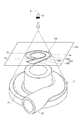
- FIG. 2 is a perspective view showing a scroll and a projection surface.
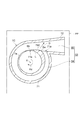
- FIG. 3 is a scroll according to the first embodiment, and is a diagram showing the shape of the inner surface of the flow path mainly shown on the projection surface.
- FIG. 4 is a scroll according to the second embodiment, and is a diagram mainly showing the shape of the inner surface of the flow path shown on the projection plane.
- FIG. 5 is a scroll according to the third embodiment, and is a diagram mainly showing the shape of the inner surface of the flow path shown on the projection plane.
- FIG. 6 is a scroll according to the fourth embodiment, and is a diagram showing the shape of the inner surface of the flow path mainly shown on the projection surface.
- FIG. 3 is a scroll according to the first embodiment, and is a diagram showing the shape of the inner surface of the flow path mainly shown on the projection surface.
- FIG. 4 is a scroll according to the second embodiment,
- FIG. 7 is a diagram showing a comparison of the shape of the protrusions shown on the projection surface for the scrolls according to the first to fourth embodiments.
- FIG. 8 is a diagram illustrating an entropy contour drawn by connecting isentropic points for the scroll according to the first embodiment.
- FIG. 9 is a diagram showing a comparative form in which no protrusion is formed, and scroll entropy contours according to the second to fourth embodiments.
- FIG. 9A is a comparative example
- FIG. 9B is a second figure.
- FIG. 4C is a diagram of the third embodiment
- FIG. 4D is a diagram of the fourth embodiment.
- FIG. 10 is a diagram showing a Mach number contour of the scroll according to the comparative embodiment in which no protrusion is formed and the first embodiment.
- One aspect of the present disclosure includes an impeller and a scroll that is disposed around the impeller and includes a flow path along a rotation direction of the impeller, and the scroll is wound on an end point side of the flow path along the rotation direction.
- the inner surface of the flow path on the projection plane Is a centrifugal compressor comprising a projecting portion of the curved shape
- the inventor has found that there is a possibility that the fluid peels from the inner surface of the scroll flow path, and that the peeling is likely to occur mainly in the vicinity of the connection portion between the winding start portion and the discharge portion. Furthermore, the inventor has found that it is effective to reduce fluid separation by providing a curved protrusion at this position, and has arrived at the present disclosure. That is, according to said aspect, it can reduce that a fluid peels from the flow path inner surface of a scroll, and can improve compression performance.
- the upstream inner surface that is opposite to the rotation direction from the protrusion and the protrusion may be a centrifugal compressor in which the tangential inclination is continuous.
- the upstream inner surface and the protruding portion are smoothly connected, and the flow of fluid is smooth, which is advantageous in suppressing separation.
- the downstream inner surface that is in the rotational direction of the projecting portion and the projecting portion may be a centrifugal compressor in which the tangential inclination continues.
- the inner surface of the downstream side and the protruding portion are smoothly connected, and for example, it is easy to prevent the occurrence of vortex on the downstream side of the protruding portion, which is advantageous in suppressing separation.
- Another aspect of the present disclosure includes an impeller and a scroll that is disposed around the impeller and includes a flow path along a rotation direction of the impeller, and the scroll is on an end point side of the flow path along the rotation direction.
- a discharge start portion arranged at the start point side of the flow path along the rotation direction, a winding start portion connected to the discharge section, and an inner surface of the flow path facing the flow path, with respect to the scroll, on the rotation axis of the impeller
- the flow path is projected on the projection plane, and is a reference on the rotation axis side at the connection portion between the winding start portion and the discharge portion.
- centrifugal compressor provided with a projecting portion of the curved shape projecting outward is centrifugal direction.
- the supercharger 1 is applied to, for example, an internal combustion engine of a ship or a vehicle.
- the supercharger 1 includes a turbine 2 and a compressor (centrifugal compressor) 3.
- the turbine 2 includes a turbine housing 4 and a turbine impeller 16 accommodated in the turbine housing 4.
- the compressor 3 includes a compressor housing 5 and a compressor wheel (impeller) 17 accommodated in the compressor housing 5.
- the turbine impeller 16 is provided at one end of the rotating shaft 14, and the compressor impeller 17 is provided at the other end of the rotating shaft 14.
- a bearing housing 13 is provided between the turbine housing 4 and the compressor housing 5.
- the rotating shaft 14 is rotatably supported by the bearing housing 13 via a bearing 15, and the rotating shaft 14, the turbine impeller 16 and the compressor impeller 17 rotate around the rotation axis X as an integral rotating body 12. .
- the turbine housing 4 is provided with an exhaust gas inlet (not shown) and an exhaust gas outlet 10. Exhaust gas discharged from an internal combustion engine (not shown) flows into the turbine housing 4 through the exhaust gas inlet, rotates the turbine impeller 16, and then flows out of the turbine housing 4 through the exhaust gas outlet 10. To do.
- the compressor housing 5 is provided with a suction portion 9 and a discharge portion (not shown).
- the compressor impeller 17 rotates via the rotating shaft 14.
- the rotating compressor wheel 17 sucks an external gas (fluid) such as air through the suction part 9, compresses it, and discharges it from the discharge part.
- the compressed gas discharged from the discharge unit is supplied to the internal combustion engine described above.
- the compressor housing 5 includes a diffuser 6 disposed around the compressor impeller 17 and a scroll 7 ⁇ / b> A disposed around the diffuser 6.
- the scroll 7 ⁇ / b> A includes a volute portion 71 (see FIG. 2) disposed around the compressor impeller 17 in a single spiral shape, and a discharge portion 72 formed integrally with the volute portion 71.
- the scroll 7 ⁇ / b> A is formed including a flow path 53. In other words, the flow path 53 through which the gas introduced from the diffuser 6 passes is formed in the scroll 7 ⁇ / b> A, and the scroll 7 ⁇ / b> A has a flow path inner surface 7 a that faces the flow path 53.
- a flow path 53 (see FIG. 3) of the scroll 7 ⁇ / b> A includes a scroll flow path 54 formed inside the volute part 71, a discharge flow path 55 formed inside the discharge part 72, and communicated with the scroll flow path 54. It is equipped with.
- the scroll flow path 54 is a flow path along the rotation direction Rd of the compressor wheel 17, and is connected to the discharge flow path 55 along the gas flow as an example on the end point side of the rotation direction Rd.
- the starting point side of the scroll flow path 54 is connected to the side of the discharge flow path 55.
- the direction of the discharge flow channel 55 is not limited to the tangential direction on the end point side of the scroll flow channel 54, for example, and the direction may be appropriately curved or the like depending on the surrounding equipment or piping. .
- the volute part 71 includes a winding start part 71 a that is the start point side of the scroll flow path 54 and a winding end part 71 b that is the end point side of the scroll flow path 54.
- the winding start portion 71 a is a portion where the scroll flow path 54 is connected to the side of the discharge flow path 55, and is outward in the centrifugal direction D of the winding start portion 71 a, that is, the rotation axis X across the scroll flow path 54.
- a tongue portion 71c is formed on the side opposite to the side (inner side).
- the start point side of the scroll flow path 54 is substantially the same.
- the end point side means the portion which becomes the upstream end, and the end point side means the portion which becomes the downstream end substantially.
- the winding end portion 71b means a terminal position in the rotational direction Rd that can define A / R when designing the scroll 7A, and usually has a maximum value in many cases.
- the end-of-winding portion 71b can also be defined as the position of the maximum rotation angle at which A / R can be defined by design when the rotation angle is assumed with reference to the winding start portion 71a.
- the scroll flow path 54 includes a rotation axis X and has a substantially circular shape as an example in a cross section along the rotation axis X. “R” (see FIG. 1) is rotated from the centroid Cf of this cross section. It is the distance to the axis X, and “A” means a substantially circular cross-sectional area.
- a rotation angle ⁇ (see FIG. 3) is a winding end portion 71b with respect to a reference start point Ba described later, and this rotation angle ⁇ is the rotation of the compressor wheel 17. For example, ⁇ 60 ° when the direction Rd is positive.
- a projection plane PP is assumed when the viewpoint E is placed on the rotation axis X of the compressor wheel 17 and on the gas suction side with respect to the scroll 7A. it can.
- a curved projecting portion 75A is formed in the discharge portion 72. The protrusion 75A will be described in detail.
- the connecting portion between the winding start portion 71 a and the discharge portion 72 is connected to the rotation axis X side (with the scroll flow channel 54 interposed therebetween).
- An inner point and a point on the tongue 71c side (outer side) can be assumed, and the inner point is assumed as the reference start point Ba.
- a point on the rotation axis X side (inner side) and an outer point can be assumed with the discharge flow channel 55 interposed therebetween, and the inner point is assumed as the reference end point Bb.
- the flow path inner surface 7a of the scroll 7A according to the present embodiment has a portion protruding outward from the reference straight line L in the centrifugal direction D, and the protruding portion is a curved protrusion 75A.
- the projecting portion 75A has a smooth curved shape with a continuous tangential inclination as a whole, and may include a straight portion in part.
- FIG. 4 relates to the second embodiment, and includes a curved projecting portion 75B projecting outward from the reference straight line L in the centrifugal direction D.
- FIG. 5 relates to the third embodiment, and includes a curved projecting portion 75 ⁇ / b> C projecting outward from the reference straight line L in the centrifugal direction D.
- FIG. 6 relates to the fourth embodiment, and includes a curved projecting portion 75D projecting outward from the reference straight line L in the centrifugal direction D.
- FIG. 7 is a diagram showing a comparison of the protrusions 75A, 75B, 75C, and 75D according to each embodiment.
- the protrusion 75A according to the first embodiment is shown by a solid line, and the protrusion according to the second embodiment.
- the part 75B is indicated by a broken line, the protrusion 75C according to the third embodiment is indicated by a one-dot chain line, and the protrusion 75D according to the fourth embodiment is indicated by a two-dot chain line.
- the upstream inner surface 7b and the protrusions 75A, 75B, 75C, and 75D that are opposite to the rotation direction Rd from the protrusions 75A, 75B, 75C, and 75D.
- the downstream inner surface 7c that is on the forward direction side with respect to the rotation direction Rd with respect to the protrusions 75A, 75B, 75C, and 75D and the protrusions 75A, 75B, 75C, and 75D are tangential.
- the slope is continuous. That is, the protrusions 75A, 75B, 75C, and 75D and the downstream inner surface 7c are smoothly connected without being bent.
- the projecting portions 75A, 75B, and 75C on the projection surface PP that is, the most projecting position 75a of the projecting portions 75A, 75B, 75C, and 75D according to the first, second, third, and fourth embodiments. , 75D, the position farthest from the reference straight line L is closer to the reference start point Ba than the center La of the reference straight line L.
- the protrusion rate Pr of each protrusion 75A, 75B, 75C, 75D is defined by the following equation (1). Specifically, the distance between the most protruding position 75a of each of the projecting portions 75A, 75B, 75C, and 75D and the reference straight line L is defined as dx. Further, as described above, at the winding end portion 71b, a point on the rotation axis X side (inner side) and an outer point Bx can be assumed with the discharge flow channel 55 interposed therebetween, and from the reference end point Bb, which is an inner point, to the rotation axis X. Is the innermost radius Ra, and the distance from the outer point Bx to the rotation axis X is the outermost radius Rb. The difference between the outermost radius Rb and the innermost radius Ra is defined as a radius difference ⁇ R, and the ratio of the distance dx to the radius difference ⁇ R is defined as a protrusion rate Pr.
- the protrusion rate Pr can be set to 0.050 or more, for example, and more preferably 0.100 or more. Further, the protrusion rate Pr can be set to 0.400 or less, preferably 0.300 or less, and more preferably 0.200 or less. Specifically, the protrusion rate Pr of the protrusion 75A according to the first embodiment is 0.147, and the protrusion rate Pr of the protrusion 75B according to the second embodiment is 0.140, according to the third embodiment. The protrusion rate Pr of the protrusion 75C is 0.110, and the protrusion rate Pr of the protrusion 75C according to the fourth embodiment is 0.223.
- the protrusions 75A, 75B, 75C, and 75D protrude outward in the centrifugal direction D in the entire region of the reference straight line L that connects the reference start point Ba to the reference end point Bb.
- the protrusions 75A, 75B, 75C, and 75D may protrude at a part of the reference straight line L.
- the upstream inner surface 7b may be formed so as to overlap the reference straight line L from the reference end point Bb.
- the downstream inner surface 7c may be formed so as to overlap the reference straight line L from the reference start point Ba.
- the protrusions 75A, 75B, 75C, and 75D may be connected to the upstream inner surface 7b and the downstream inner surface 7c, and as a result, a part of the reference straight line L may be projected.
- the inventor has a possibility that the fluid may peel from the flow path inner surface 107 a of the scroll 107, and the peeling is mainly performed between the winding start portion 171 a and the discharge portion 172. It has been found that it is likely to occur on the inner surface of the flow path 107a on the inner side near the connection portion and close to the rotation axis.
- the angular velocity of the flowing gas increases as it approaches the rotation axis. That is, it can be inferred that the angular velocity of the gas flowing along the inner flow path inner surface 107a close to the rotation axis increases, and an environment in which separation is likely to occur occurs.
- the inventor presumed that the occurrence of peeling could be reduced by projecting the inner surface of the flow path so as to fill the region where peeling is likely to occur, and intensively studied based on the idea.
- the inventor has confirmed that by providing the above-described protrusions 75A, 75B, 75C, and 75D, fluid separation can be reduced, and as a result, compression performance can be improved.
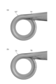
- FIG. 8 is a diagram illustrating an entropy contour drawn by connecting isentropic points with respect to the scroll 7A according to the first embodiment
- FIG. 9A illustrates the scroll 107 according to the comparative example. It is a figure which shows the entropy contour drawn by connecting the entropy points.
- the black region S is a part that is peeled off, but the black region shown in FIG. 8 is compared to the black region S shown in FIG. It can be confirmed that the region S is smaller.
- FIG. 10A is a diagram showing a Mach number contour of the scroll 107 according to the comparative embodiment
- FIG. 10B is a diagram showing a Mach number contour of the scroll 7A according to the first embodiment.
- a large vortex Va is formed at the separation site, whereas the vortex Vb shown in FIG. 10 (b) is extremely small.
- the pressure loss of the scroll 7A according to the first embodiment is smaller than that of the comparative embodiment, and the compression performance can be improved.
- FIG. 9B is a diagram showing an entropy contour of the scroll 7B according to the second embodiment
- FIG. 9C shows an entropy contour of the scroll 7C according to the third embodiment
- FIG. 9D shows a 7D entropy contour according to the fourth embodiment.
- the black region S according to the second to fourth embodiments shown in FIGS. 9B to 9D is smaller. That is, it can be inferred that the pressure loss is smaller in the scrolls 7B, 7C, and 7D according to the second to fourth embodiments and the compression performance can be improved as compared with the comparative embodiment.
- the scroll 7A according to the first embodiment hardly causes separation.
- the scrolls 7B and 7C according to the second and third embodiments are unlikely to peel off. It can be inferred that the scroll 7D according to the fourth embodiment is slightly peelable as compared with the scrolls 7A, 7B, 7C according to the first, second, and third embodiments.
- the upstream inner surface 7b and the projecting portions 75A, 75B, 75C, and 75D are smoothly connected, and the gas flow is smoothly performed.
- the downstream inner surface 7c and the projecting portions 75A, 75B, 75C, and 75D are smoothly connected.
- the projecting portions 75A, 75B, 75C, 75D are smoothly connected to both the upstream inner surface 7b and the downstream inner surface 7c.
- the protrusions 75A, 75B, 75C, and 75D may be smoothly connected to only one of the upstream inner surface 7b and the downstream inner surface 7c.
- the present invention can be implemented in various forms including various modifications and improvements based on the knowledge of those skilled in the art including the above-described embodiments. Moreover, it is also possible to configure a modification of each example by using the technical matters described in the above-described embodiments. You may use combining the structure of each embodiment suitably.
- the present invention is not limited to that applied to a supercharger for automobiles, and may be applied to ships and the like. Furthermore, the present invention may be applied to a centrifugal compressor other than the supercharger.
- Compressor centrifugal compressor 7A, 7B, 7C, 7D Scroll 7a Channel inner surface 7b Upstream inner surface 7c Downstream inner surface 17
- Compressor impeller 53 Channel 71b Winding end portion 71a Winding start portion 75A, 75B, 75C, 75D Protruding portion 75a Most protruding portion Position E Viewpoint D Centrifugal direction PP Projection plane ⁇ Rotation angle Ba Reference start point Bb Reference end point L Reference straight line
Landscapes
- Engineering & Computer Science (AREA)
- Mechanical Engineering (AREA)
- General Engineering & Computer Science (AREA)
- Chemical & Material Sciences (AREA)
- Combustion & Propulsion (AREA)
- Structures Of Non-Positive Displacement Pumps (AREA)
Abstract
Dans ce compresseur (3), une volute (7A) est pourvue d'une section de fin d'enroulement (71b), d'une section de sortie (72) reliée à la section de fin d'enroulement (71b), d'une section de début d'enroulement (71a) reliée à la section de sortie (72), et d'une surface intérieure de chemin d'écoulement (7a). Lorsqu'un plan de projection (PP) est préétabli pour un cas dans lequel un point de vue (E) est placé sur l'axe de rotation (X) d'une roue (17) de compresseur et sur un côté admission de fluide par rapport à la volute (7A), la surface intérieure de chemin d'écoulement (7a) est projetée sur le plan de projection (PP) et la surface intérieure de chemin d'écoulement (7a) sur le plan de projection (PP) est pourvue d'une saillie (75A) qui présente une forme incurvée et qui fait saillie davantage vers l'extérieur qu'une ligne droite de référence (L) lorsqu'un point de départ de référence (Ba) sur le côté axe de rotation (X) dans une partie reliant la section de début d'enroulement (71a) et la section de sortie (72) et un point de fin de référence (Bb) sur le côté axe de rotation (X) dans la section de fin d'enroulement (71b) sont préétablis et une ligne droite de référence (L) reliant le point de départ de référence (Ba) et le point de fin de référence (Bb) sur le plan de projection (PP) est préétabli.
Priority Applications (4)
| Application Number | Priority Date | Filing Date | Title |
|---|---|---|---|
| CN201780025285.6A CN109072940B (zh) | 2016-07-01 | 2017-06-21 | 离心压缩机 |
| JP2018525096A JP6638811B2 (ja) | 2016-07-01 | 2017-06-21 | 遠心圧縮機 |
| US16/305,478 US11209015B2 (en) | 2016-07-01 | 2017-06-21 | Centrifugal compressor |
| DE112017003333.0T DE112017003333T5 (de) | 2016-07-01 | 2017-06-21 | Radialverdichter |
Applications Claiming Priority (2)
| Application Number | Priority Date | Filing Date | Title |
|---|---|---|---|
| JP2016131750 | 2016-07-01 | ||
| JP2016-131750 | 2016-07-01 |
Publications (1)
| Publication Number | Publication Date |
|---|---|
| WO2018003632A1 true WO2018003632A1 (fr) | 2018-01-04 |
Family
ID=60787123
Family Applications (1)
| Application Number | Title | Priority Date | Filing Date |
|---|---|---|---|
| PCT/JP2017/022876 Ceased WO2018003632A1 (fr) | 2016-07-01 | 2017-06-21 | Compresseur centrifuge |
Country Status (5)
| Country | Link |
|---|---|
| US (1) | US11209015B2 (fr) |
| JP (1) | JP6638811B2 (fr) |
| CN (1) | CN109072940B (fr) |
| DE (1) | DE112017003333T5 (fr) |
| WO (1) | WO2018003632A1 (fr) |
Cited By (3)
| Publication number | Priority date | Publication date | Assignee | Title |
|---|---|---|---|---|
| JP2019190385A (ja) * | 2018-04-26 | 2019-10-31 | 三菱重工コンプレッサ株式会社 | 遠心圧縮機 |
| WO2020245934A1 (fr) * | 2019-06-05 | 2020-12-10 | 三菱重工エンジン&ターボチャージャ株式会社 | Structure de spirale pour compresseur centrifuge, et compresseur centrifuge |
| US11131319B2 (en) * | 2017-08-31 | 2021-09-28 | Mitsubishi Heavy Industries Compressor Corporation | Centrifugal compressor |
Families Citing this family (1)
| Publication number | Priority date | Publication date | Assignee | Title |
|---|---|---|---|---|
| US11788557B1 (en) | 2022-05-06 | 2023-10-17 | Ingersoll-Rand Industrial U.S., Inc. | Centrifugal acceleration stabilizer |
Citations (4)
| Publication number | Priority date | Publication date | Assignee | Title |
|---|---|---|---|---|
| US20050232762A1 (en) * | 2004-04-20 | 2005-10-20 | Honeywell International Inc. | Turbomachine compressor scroll with load-carrying inlet vanes |
| JP2008163803A (ja) * | 2006-12-27 | 2008-07-17 | Toyota Motor Corp | 遠心圧縮機 |
| JP2011099413A (ja) * | 2009-11-09 | 2011-05-19 | Mitsubishi Heavy Ind Ltd | 多翼遠心ファンおよびそれを用いた空気調和機 |
| JP2015227619A (ja) * | 2014-05-30 | 2015-12-17 | 株式会社オティックス | ターボチャージャ |
Family Cites Families (11)
| Publication number | Priority date | Publication date | Assignee | Title |
|---|---|---|---|---|
| JPH03217699A (ja) | 1990-01-23 | 1991-09-25 | Nissan Motor Co Ltd | 圧縮機のスクロール構造 |
| JPH0495697U (fr) | 1991-01-17 | 1992-08-19 | ||
| JP3404858B2 (ja) | 1994-02-07 | 2003-05-12 | 株式会社デンソー | 遠心多翼送風機 |
| JPH10131895A (ja) | 1996-10-30 | 1998-05-19 | Kobe Steel Ltd | 遠心圧縮機の渦巻ケーシング |
| CN2541643Y (zh) | 2002-01-16 | 2003-03-26 | 林钧浩 | 外流抽吸风机 |
| DE102007034236A1 (de) | 2007-07-23 | 2009-02-05 | Continental Automotive Gmbh | Radialverdichter mit einem Diffusor für den Einsatz bei einem Turbolader |
| JP5517914B2 (ja) | 2010-12-27 | 2014-06-11 | 三菱重工業株式会社 | 遠心圧縮機のスクロール構造 |
| JP5479316B2 (ja) | 2010-12-28 | 2014-04-23 | 三菱重工業株式会社 | 遠心圧縮機のスクロール構造 |
| JP5439423B2 (ja) | 2011-03-25 | 2014-03-12 | 三菱重工業株式会社 | 遠心圧縮機のスクロール形状 |
| CN105264236B (zh) * | 2013-11-22 | 2018-02-13 | 株式会社Ihi | 离心压缩机及增压器 |
| WO2017072900A1 (fr) * | 2015-10-29 | 2017-05-04 | 三菱重工業株式会社 | Carter en spirale et compresseur centrifuge |
-
2017
- 2017-06-21 WO PCT/JP2017/022876 patent/WO2018003632A1/fr not_active Ceased
- 2017-06-21 CN CN201780025285.6A patent/CN109072940B/zh active Active
- 2017-06-21 US US16/305,478 patent/US11209015B2/en active Active
- 2017-06-21 DE DE112017003333.0T patent/DE112017003333T5/de active Pending
- 2017-06-21 JP JP2018525096A patent/JP6638811B2/ja active Active
Patent Citations (4)
| Publication number | Priority date | Publication date | Assignee | Title |
|---|---|---|---|---|
| US20050232762A1 (en) * | 2004-04-20 | 2005-10-20 | Honeywell International Inc. | Turbomachine compressor scroll with load-carrying inlet vanes |
| JP2008163803A (ja) * | 2006-12-27 | 2008-07-17 | Toyota Motor Corp | 遠心圧縮機 |
| JP2011099413A (ja) * | 2009-11-09 | 2011-05-19 | Mitsubishi Heavy Ind Ltd | 多翼遠心ファンおよびそれを用いた空気調和機 |
| JP2015227619A (ja) * | 2014-05-30 | 2015-12-17 | 株式会社オティックス | ターボチャージャ |
Cited By (10)
| Publication number | Priority date | Publication date | Assignee | Title |
|---|---|---|---|---|
| US11131319B2 (en) * | 2017-08-31 | 2021-09-28 | Mitsubishi Heavy Industries Compressor Corporation | Centrifugal compressor |
| JP2019190385A (ja) * | 2018-04-26 | 2019-10-31 | 三菱重工コンプレッサ株式会社 | 遠心圧縮機 |
| WO2019207950A1 (fr) * | 2018-04-26 | 2019-10-31 | 三菱重工コンプレッサ株式会社 | Compresseur centrifuge |
| CN111989495A (zh) * | 2018-04-26 | 2020-11-24 | 三菱重工压缩机有限公司 | 离心压缩机 |
| EP3770442A4 (fr) * | 2018-04-26 | 2021-05-12 | Mitsubishi Heavy Industries Compressor Corporation | Compresseur centrifuge |
| JP7013316B2 (ja) | 2018-04-26 | 2022-01-31 | 三菱重工コンプレッサ株式会社 | 遠心圧縮機 |
| US11378096B2 (en) | 2018-04-26 | 2022-07-05 | Mitsubishi Heavy Industries Compressor Corporation | Centrifugal compressor |
| WO2020245934A1 (fr) * | 2019-06-05 | 2020-12-10 | 三菱重工エンジン&ターボチャージャ株式会社 | Structure de spirale pour compresseur centrifuge, et compresseur centrifuge |
| JPWO2020245934A1 (fr) * | 2019-06-05 | 2020-12-10 | ||
| JP7134348B2 (ja) | 2019-06-05 | 2022-09-09 | 三菱重工エンジン&ターボチャージャ株式会社 | 遠心圧縮機のスクロール構造及び遠心圧縮機 |
Also Published As
| Publication number | Publication date |
|---|---|
| CN109072940A (zh) | 2018-12-21 |
| US11209015B2 (en) | 2021-12-28 |
| CN109072940B (zh) | 2020-05-26 |
| US20210222703A1 (en) | 2021-07-22 |
| JP6638811B2 (ja) | 2020-01-29 |
| DE112017003333T5 (de) | 2019-03-14 |
| JPWO2018003632A1 (ja) | 2019-03-14 |
Similar Documents
| Publication | Publication Date | Title |
|---|---|---|
| US9874224B2 (en) | Centrifugal compressor and turbocharger | |
| EP2960528B1 (fr) | Compresseur centrifuge | |
| JP6638811B2 (ja) | 遠心圧縮機 | |
| JP5369723B2 (ja) | 遠心圧縮機 | |
| CN107304774A (zh) | 压缩机 | |
| JP6642711B2 (ja) | 遠心圧縮機 | |
| JP2010270641A (ja) | 遠心圧縮機 | |
| JP2008075536A (ja) | 遠心圧縮機 | |
| JP2015105644A (ja) | 過給機用圧縮機 | |
| JP4431531B2 (ja) | 過給機の気流音低減装置 | |
| JP6613838B2 (ja) | 遠心圧縮機 | |
| CN108700085A (zh) | 压缩机叶轮和涡轮增压器 | |
| JP2012211572A (ja) | ターボチャージャ | |
| CN102667176B (zh) | 离心泵 | |
| JP2012177357A (ja) | ラジアルタービン及び過給機 | |
| JP6299833B2 (ja) | タービン及び車両用過給機 | |
| JP6924844B2 (ja) | コンプレッサインペラ、コンプレッサ及びターボチャージャ | |
| JP7146364B2 (ja) | 遠心圧縮機 | |
| JP2019019695A (ja) | 遠心圧縮機インペラ及び遠心圧縮機 | |
| JP6844341B2 (ja) | タービンハウジング | |
| JP2017057779A (ja) | ターボチャージャ | |
| JP2012255426A (ja) | タービン及び車両用過給機 | |
| CN115698516B (zh) | 蜗壳和离心压缩机 | |
| CN111356843A (zh) | 多级离心压缩机、壳体以及回流翼片 | |
| WO2018174166A1 (fr) | Compresseur centrifuge |
Legal Events
| Date | Code | Title | Description |
|---|---|---|---|
| ENP | Entry into the national phase |
Ref document number: 2018525096 Country of ref document: JP Kind code of ref document: A |
|
| 121 | Ep: the epo has been informed by wipo that ep was designated in this application |
Ref document number: 17819991 Country of ref document: EP Kind code of ref document: A1 |
|
| 122 | Ep: pct application non-entry in european phase |
Ref document number: 17819991 Country of ref document: EP Kind code of ref document: A1 |