WO2018003733A1 - Mécanisme de retenue de pièce - Google Patents
Mécanisme de retenue de pièce Download PDFInfo
- Publication number
- WO2018003733A1 WO2018003733A1 PCT/JP2017/023356 JP2017023356W WO2018003733A1 WO 2018003733 A1 WO2018003733 A1 WO 2018003733A1 JP 2017023356 W JP2017023356 W JP 2017023356W WO 2018003733 A1 WO2018003733 A1 WO 2018003733A1
- Authority
- WO
- WIPO (PCT)
- Prior art keywords
- surface portion
- support
- arm
- holding mechanism
- face
- Prior art date
- Legal status (The legal status is an assumption and is not a legal conclusion. Google has not performed a legal analysis and makes no representation as to the accuracy of the status listed.)
- Ceased
Links
Images




Classifications
-
- B—PERFORMING OPERATIONS; TRANSPORTING
- B25—HAND TOOLS; PORTABLE POWER-DRIVEN TOOLS; MANIPULATORS
- B25J—MANIPULATORS; CHAMBERS PROVIDED WITH MANIPULATION DEVICES
- B25J9/00—Program-controlled manipulators
- B25J9/0084—Program-controlled manipulators comprising a plurality of manipulators
- B25J9/0087—Dual arms
-
- B—PERFORMING OPERATIONS; TRANSPORTING
- B25—HAND TOOLS; PORTABLE POWER-DRIVEN TOOLS; MANIPULATORS
- B25J—MANIPULATORS; CHAMBERS PROVIDED WITH MANIPULATION DEVICES
- B25J15/00—Gripping heads and other end effectors
- B25J15/0028—Gripping heads and other end effectors with movable, e.g. pivoting gripping jaw surfaces
-
- B—PERFORMING OPERATIONS; TRANSPORTING
- B25—HAND TOOLS; PORTABLE POWER-DRIVEN TOOLS; MANIPULATORS
- B25J—MANIPULATORS; CHAMBERS PROVIDED WITH MANIPULATION DEVICES
- B25J15/00—Gripping heads and other end effectors
- B25J15/0033—Gripping heads and other end effectors with gripping surfaces having special shapes
-
- B—PERFORMING OPERATIONS; TRANSPORTING
- B25—HAND TOOLS; PORTABLE POWER-DRIVEN TOOLS; MANIPULATORS
- B25J—MANIPULATORS; CHAMBERS PROVIDED WITH MANIPULATION DEVICES
- B25J15/00—Gripping heads and other end effectors
- B25J15/0004—Gripping heads and other end effectors with provision for adjusting the gripped object in the hand
-
- B—PERFORMING OPERATIONS; TRANSPORTING
- B25—HAND TOOLS; PORTABLE POWER-DRIVEN TOOLS; MANIPULATORS
- B25J—MANIPULATORS; CHAMBERS PROVIDED WITH MANIPULATION DEVICES
- B25J15/00—Gripping heads and other end effectors
- B25J15/0014—Gripping heads and other end effectors having fork, comb or plate shaped means for engaging the lower surface on a object to be transported
-
- B—PERFORMING OPERATIONS; TRANSPORTING
- B65—CONVEYING; PACKING; STORING; HANDLING THIN OR FILAMENTARY MATERIAL
- B65G—TRANSPORT OR STORAGE DEVICES, e.g. CONVEYORS FOR LOADING OR TIPPING, SHOP CONVEYOR SYSTEMS OR PNEUMATIC TUBE CONVEYORS
- B65G47/00—Article or material-handling devices associated with conveyors; Methods employing such devices
- B65G47/74—Feeding, transfer, or discharging devices of particular kinds or types
- B65G47/90—Devices for picking-up and depositing articles or materials
-
- B—PERFORMING OPERATIONS; TRANSPORTING
- B65—CONVEYING; PACKING; STORING; HANDLING THIN OR FILAMENTARY MATERIAL
- B65G—TRANSPORT OR STORAGE DEVICES, e.g. CONVEYORS FOR LOADING OR TIPPING, SHOP CONVEYOR SYSTEMS OR PNEUMATIC TUBE CONVEYORS
- B65G49/00—Conveying systems characterised by their application for specified purposes not otherwise provided for
- B65G49/05—Conveying systems characterised by their application for specified purposes not otherwise provided for for fragile or damageable materials or articles
- B65G49/06—Conveying systems characterised by their application for specified purposes not otherwise provided for for fragile or damageable materials or articles for fragile sheets, e.g. glass
- B65G49/061—Lifting, gripping, or carrying means, for one or more sheets forming independent means of transport, e.g. suction cups, transport frames
-
- B—PERFORMING OPERATIONS; TRANSPORTING
- B65—CONVEYING; PACKING; STORING; HANDLING THIN OR FILAMENTARY MATERIAL
- B65G—TRANSPORT OR STORAGE DEVICES, e.g. CONVEYORS FOR LOADING OR TIPPING, SHOP CONVEYOR SYSTEMS OR PNEUMATIC TUBE CONVEYORS
- B65G49/00—Conveying systems characterised by their application for specified purposes not otherwise provided for
- B65G49/05—Conveying systems characterised by their application for specified purposes not otherwise provided for for fragile or damageable materials or articles
- B65G49/06—Conveying systems characterised by their application for specified purposes not otherwise provided for for fragile or damageable materials or articles for fragile sheets, e.g. glass
- B65G49/067—Sheet handling, means, e.g. manipulators, devices for turning or tilting sheet glass
-
- B—PERFORMING OPERATIONS; TRANSPORTING
- B65—CONVEYING; PACKING; STORING; HANDLING THIN OR FILAMENTARY MATERIAL
- B65G—TRANSPORT OR STORAGE DEVICES, e.g. CONVEYORS FOR LOADING OR TIPPING, SHOP CONVEYOR SYSTEMS OR PNEUMATIC TUBE CONVEYORS
- B65G2201/00—Indexing codes relating to handling devices, e.g. conveyors, characterised by the type of product or load being conveyed or handled
- B65G2201/02—Articles
- B65G2201/0214—Articles of special size, shape or weigh
- B65G2201/022—Flat
Definitions
- the present invention relates to a workpiece holding mechanism such as a substrate.
- the substrate transport robot transports the substrate by spatially moving the arm holding the substrate in a three-dimensional direction.
- Semiconductor substrates are weaker than printed circuit boards and other board-like electronic components.
- the substrate is held by placing the substrate on the main surface of the substrate transport blade.
- Patent Document 1 and Patent Document 2 disclose a substrate transport blade that holds a substrate in a state where the substrate is fitted in a recess and positions the substrate.
- an object of the present invention is to provide a workpiece holding mechanism having an alignment function.
- a workpiece holding mechanism is a workpiece holding mechanism including a first arm and a second arm configured to be movable in a three-dimensional space, and is provided at a tip of the first arm.
- a first support body having a first surface extending in the first direction in a horizontal plane, or a first surface portion constituted by a plurality of surfaces arranged in parallel in the first direction, and provided at the tip of the second arm.
- a second support member having a second surface portion that is formed by one surface facing the first surface portion and extending in the first direction, or a plurality of surfaces arranged in parallel in the first direction.
- a third support body provided on the first support body, the third support body having a third surface portion located on the second surface portion side of the first surface portion and at a height position corresponding to a lower end of the first surface portion; , Provided on the second support, and closer to the first surface portion than the second surface portion.
- a fourth support body having a fourth surface portion at a height corresponding to the lower end of the second surface portion, and provided on the first support body, at one end of the first surface portion in the first direction,
- a fifth support body having a fifth surface portion located on the second surface portion side with respect to the first surface portion and located above the third surface portion; and provided on the second support body, the first surface portion
- a sixth surface portion positioned on the first surface portion side of the second surface portion and above the fourth surface portion at the end portion of the second surface portion facing the other end in the first direction.
- at least one of the third surface portion and the fourth surface portion is one surface extending in the first direction, or a plurality of juxtaposed in the first direction. Consists of faces.
- the first surface portion and the second surface portion are maintained parallel to each other, and the third surface portion and the fourth surface portion are maintained at the same height while the first surface portion and the second surface portion are kept in the same state.
- the second support relative to the first support so as to adjust the distance to the surface portion
- the left and right ends of the substrate can be supported while the height of the substrate is adjusted horizontally.
- the first support body while maintaining the first surface portion and the second surface portion parallel to each other and maintaining the same height of the third surface portion and the fourth surface portion, the first support body
- the front and rear ends of the substrate can be supported by relatively moving the second support in the first direction.
- the substrate can be held in a state in which the rotational direction, inclination, and height deviation as viewed from the plane of the substrate are adjusted, so that the substrate can be transported to a predetermined position in the three-dimensional space.
- the stacked substrates can be set in an inspection apparatus (for example, ICT).
- the work holding mechanism maintains the first surface portion and the second surface portion in parallel with each other, and maintains the same height of the third surface portion and the fourth surface portion.
- the second support may move relative to the first support so as to adjust the distance between the first surface and the second surface.
- the work holding mechanism maintains the first surface portion and the second surface portion parallel to each other, and maintains the same height of the third surface portion and the fourth surface portion,
- the second support may move in the first direction relative to the first support.
- the work holding mechanism may be constituted by a robot having the first arm and the second arm.
- a workpiece holding mechanism having an alignment function can be provided.
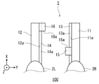
- FIG. 1 is a perspective view showing the configuration of the substrate holding mechanism according to the first embodiment of the present invention.
- FIG. 2 is a plan view of the substrate holding mechanism of FIG.
- FIG. 3 is a front view showing the configuration of the robot.
- FIG. 4 is a block diagram illustrating a schematic configuration of the control device.
- FIG. 5 is a side view showing an example of the work site of the robot.
- FIG. 6 is a diagram schematically illustrating the first operation of the robot.
- FIG. 7 is a diagram schematically illustrating the second operation of the robot.
- FIG. 8 is a diagram schematically illustrating the third operation of the robot.
- FIG. 9 is a perspective view showing the configuration of the substrate holding mechanism according to the second embodiment of the present invention.
- 10 is a plan view of the substrate holding mechanism of FIG.
- FIG. 11 is a diagram schematically showing the operation of the robot.
- FIG. 1 is a perspective view showing the configuration of the substrate holding mechanism according to the first embodiment of the present invention.
- FIG. 2 is a plan view of the substrate holding mechanism of FIG.
- the substrate holding mechanism 1 is attached to the tips of a first robot arm 2R (hereinafter referred to as “first arm 2R”) and a second robot arm 2L (hereinafter referred to as “second arm 2L”) of the robot 100.
- first arm 2R a first robot arm 2R
- second robot arm 2L hereinafter referred to as “second arm 2L”
- the substrate holding mechanism 1 holds a substrate-like electronic component (workpiece) and has a substrate (workpiece) alignment function. 1 and 2, three XYZ axes orthogonal to each other are defined. These XYZ axes coincide with a hand coordinate system defined with reference to the tips of the first arm 2R and the second arm 2L.
- the substrate holding mechanism 1 includes a first support 11 provided at the tip of the first arm 2R, a second support 12 provided at the tip of the second arm 2L, and a first support 11 provided on the first support 11.
- a body 16
- the first support 11 has a rectangular parallelepiped shape here.
- the upper surface of the end of the rectangular parallelepiped is fixed to the first arm 2R via two fixtures.
- One side surface (the positive direction side of the Y axis) of the rectangular parallelepiped forms a band-like surface (first surface portion 11a) extending in the first direction (X axis direction) in the horizontal plane (XY plane).
- the second support 12 has a rectangular parallelepiped shape here.
- the upper surface of the end of the rectangular parallelepiped is fixed to the second arm 2L via two attachments.
- One side surface (the negative direction side of the Y-axis) of the rectangular parallelepiped forms a band-shaped surface (second surface portion 12a) that faces the first surface portion 11a and extends in the first direction (X-axis direction in the figure). To do.
- the third support 13 has a flat plate shape here.
- One side surface (the positive side of the Y axis) of this flat plate is fixed in contact with the first surface portion 11a.
- the upper surface of this flat plate forms a third surface portion 13a that protrudes from the lower end of the first surface portion 11a toward the second surface portion 12a and extends in the same direction (X-axis direction) as the first surface portion 11a.
- the 3rd surface part 13a is located in the 2nd surface part 12a side rather than the 1st surface part 11a, and exists in the height position equivalent to the lower end of the 1st surface part 11a.
- the fourth support 14 has a flat plate shape here.
- One side surface (the negative direction side of the Y axis) of this flat plate is fixed in contact with the second surface portion 12a.
- the upper surface of this flat plate forms a fourth surface portion 14a that protrudes from the lower end of the second surface portion 12a toward the first surface portion and extends in the same direction as the second surface portion 12a.
- the 4th surface part 14a is located in the 1st surface part 11a side rather than the 2nd surface part 12a, and exists in the height position equivalent to the lower end of the 2nd surface part 12a.
- both the third surface portion 13a and the fourth surface portion 14a are configured by a single surface extending in the first direction (the positive direction of the X axis).
- the fifth support 15 has a rectangular parallelepiped shape here.
- One side surface (the positive direction side of the Y axis) of the rectangular parallelepiped is fixed in contact with the first surface portion 11a.
- the other side surface (the positive direction side of the X axis) of the rectangular parallelepiped is located on the second surface portion 12a side from the first flat surface 11a portion at one end in the first direction (X direction) of the first surface portion 11a, and A fifth surface portion 15a located above the third surface portion 13a is formed.
- the sixth support 16 has a rectangular parallelepiped shape here.
- One side surface (the negative direction side of the Y-axis) of this rectangular parallelepiped is fixed in contact with the second surface portion 12a.
- the other side surface (the negative direction side of the X axis) of this rectangular parallelepiped is the first surface portion 11a side of the second surface portion 12a at the end of the second surface portion 12a facing the other end of the first surface portion 11a in the first direction.
- a sixth surface portion 16a positioned above the fourth surface portion 14a.
- the first surface portion 11a and the second surface portion 12a are shown to face each other and be parallel (extend in the same direction).
- the arm 2L can move the first support 11 and the second support 12 in a three-dimensional space, and the first surface portion 11a and the second surface portion 12a can be changed to arbitrary angles.
- FIG. 3 is a front view showing the configuration of the robot 100.
- the robot 100 includes a base 4, a pair of first and second arms 2 ⁇ / b> R and 2 ⁇ / b> L supported by the base 4, and a control device 3 housed in the base 4. ing.
- the left and right first arms 2R and second arms 2L are configured to be movable in a three-dimensional space.
- the first arm 2R and the second arm 2L can operate independently or operate in association with each other.
- a general horizontal articulated robot arm can be adopted, and the configuration thereof is publicly known.
- the tool (1) is fixed to the tips of the first arm 2R and the second arm 2L via a fixture, but is attached to the tips of the first arm 2R and the second arm 2L via a mechanical interface. You may attach so that attachment or detachment is possible.
- FIG. 4 is a block diagram illustrating a schematic configuration of the control device 3.
- the control device 3 includes a calculation unit 301 such as a CPU, a storage unit 302 such as a ROM and a RAM, and a servo control unit 303.
- the control device 3 is a robot controller including a computer such as a microcontroller. Note that the control device 3 may be configured by a single control device that performs centralized control, or may be configured by a plurality of control devices that perform distributed control in cooperation with each other.
- the storage unit 302 stores information such as a basic program as a robot controller and various fixed data.
- the arithmetic unit 301 controls various operations of the robot 100 by reading and executing software such as a basic program stored in the storage unit 302. That is, the arithmetic unit 301 generates a control command for the robot 100 and outputs it to the servo control unit 303.
- the servo control unit 303 is configured to control the drive of the servo motor corresponding to each joint axis of the first arm 2R and the second arm 2L of the robot 100 based on the control command generated by the calculation unit 301. Yes.
- the control device 3 also controls the operation. It may be broken. That is, the control device 3 controls the operation of the entire robot 100.
- FIG. 5 is a side view showing an example of the work site of the robot 100.
- the robot 100 is introduced to the assembly site of electronic components.
- a temporary substrate mounting table 30 is installed on the right side of the robot 100.
- a printed circuit board 40 is stacked on the temporary substrate mounting table 30. Each printed board 40 is arranged with the board side down and the circuit side up.
- An inspection apparatus 20 is installed on the left side of the robot 100.
- the inspection device 20 is an in-circuit tester (ICT). ICT electrically inspects the characteristics of individual components mounted on a substrate with a minute electric power without operating the substrate, and finds a defect that is difficult to find by visual inspection.
- the robot 100 is responsible for one end of the inspection work of the printed circuit board 40.
- the robot 100 picks up the two printed circuit boards 40 stacked on the temporary substrate mounting table 30 in order from the top, and conveys them to a predetermined position on the inspection table 20a of the inspection apparatus 20.
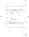
- FIG. 6 is a diagram schematically illustrating the first operation of the robot.
- FIG. 3A is a plan view of the substrate holding mechanism 1 and the printed circuit board 40 in the first operation.
- FIG. 6B is a sectional view taken along the line VI-VI.
- the control device 3 moves the first support body 11 and the second support body 12 so that the printed circuit board 40 is positioned between the first surface portion 11a and the second surface portion 12a.
- the position of the temporary substrate mounting table 30 may be stored in the storage unit 302 in advance, or may be remotely operated manually.
- the uppermost printed circuit board 40 has a rotation direction (XY plane) and a height direction (Z direction). ) May cause a shift.
- Various components are mounted on the circuit side of the printed circuit board 40. For this reason, the surface shape on the circuit side is not uniform, and such a shift is likely to occur.
- FIG. 7 is a diagram schematically illustrating the second operation of the robot 100.
- FIG. 3A is a plan view of the substrate holding mechanism 1 and the printed circuit board 40 in the first operation.
- FIG. 5B is a sectional view taken along line VII-VII.
- the control device 3 maintains a state in which the first surface portion 11a and the second surface portion 12a are parallel to each other, and the third surface portion 13a and the fourth surface portion 14a have the same height.
- the second support 12 While maintaining, the second support 12 is moved relative to the first support 11 so as to adjust the distance between the first surface 11a and the second surface 12a. Thereby, the left and right ends of the printed circuit board 40 can be supported while adjusting the height of the printed circuit board 40 horizontally.
- FIG. 8 is a diagram schematically illustrating the third operation of the robot.
- FIG. 3A is a plan view of the substrate holding mechanism 1 and the printed circuit board 40 in the first operation.
- FIG. 5B is a sectional view taken along line VII-VII.
- the control device 3 maintains a state in which the first surface portion 11a and the second surface portion 12a are parallel to each other, and the third surface portion 13a and the fourth surface portion 14a have the same height. While maintaining, the second support 12 is moved relative to the first support 11 in the first direction.
- the substrate can be held in a state in which the deviation in the rotation direction and the height direction of the printed circuit board 40 is adjusted, so that the printed circuit board 40 is transported to a predetermined position on the inspection table 30a of the inspection apparatus 20. Can do.
- the robot 100 can set the stacked printed circuit boards 40 on the inspection apparatus 20.
- FIG. 9 is a perspective view showing the configuration of the substrate holding mechanism 1A according to the second embodiment of the present invention.
- FIG. 10 is a plan view of the substrate holding mechanism 1A of FIG.
- the substrate holding mechanism 1A of the present embodiment is different from the first embodiment in that the first surface portion 11a to the sixth surface portion 16a are configured by a minimal surface at the apex of a small hemispherical member.
- the first surface portion 11a is constituted by a minimal surface at the apex of two hemispherical members arranged in parallel in the first direction (the positive direction of the X axis).
- the second surface portion 12a is configured by a minimal surface at the apex of two hemispherical members that face the first surface portion 11a and are arranged in parallel in the first direction (the positive direction of the X axis).
- the 3rd surface part 13a is comprised by the minimum surface of the vertex of one hemispherical member.
- the fourth surface portion 14a is configured by a minimal surface at the apex of two hemispherical members arranged in parallel in the first direction (the positive direction of the X axis).
- the 5th surface part 15a and the 6th surface part 16a are comprised by the minimum surface of the vertex of one hemispherical member.
- control device 3 controls the operations of the first arm 2R and the second arm 2L (first operation to third operation), as shown in FIG. 11, as shown in FIG.
- the substrate can be held in a state in which the deviation in the rotation direction and height direction of the printed circuit board 40 is adjusted. Thereby, the printed circuit board 40 can be transported to a predetermined position on the inspection table 30a of the inspection apparatus 20.
- the 1st surface part 11a and the 2nd surface part 12a may be comprised by the 3 or more several surface arranged in parallel by the 1st direction (X-axis direction).
- At least any one of the 3rd surface part 13a and the 4th surface part 14a is comprised by the one surface extended in a 1st direction (X-axis direction), or the some minimum surface arranged in parallel in the 1st direction. May be.
- the workpiece is the printed circuit board 40, but is not limited to this.
- a substrate-like electronic component such as a flexible printed circuit board, a rigid flexible circuit board, or a glass substrate of a liquid crystal display may be used.
- the workpiece is relatively stronger than the semiconductor substrate, the workpiece can be held and the workpiece alignment can be realized with the same configuration as in each of the above embodiments.
- the inspection device 20 is an in-circuit tester.
- other inspection devices such as a board tester may be used as long as they are devices that inspect board-like electronic components.
- the present invention is useful when a robot is introduced into a work site that is conventionally performed by a human.
Landscapes
- Engineering & Computer Science (AREA)
- Mechanical Engineering (AREA)
- Robotics (AREA)
- Manipulator (AREA)
- Container, Conveyance, Adherence, Positioning, Of Wafer (AREA)
Abstract
L'invention concerne un mécanisme de retenue de pièce (1) qui comprend : un premier corps de support (11) ayant une première face (11a); un deuxième corps de support (12) ayant une deuxième face (12a); un troisième corps de support (13) ayant une troisième face (13a) positionnée plus près du côté de la deuxième face que de la première face et positionnée à une hauteur correspondant au bord inférieur de la première face; un quatrième corps de support (14) ayant une quatrième face (14a) positionnée plus près du côté de la première face que de la deuxième face et positionnée à une hauteur correspondant au bord inférieur de la deuxième face; un cinquième corps de support (15) ayant une cinquième face (15a), sur une extrémité de la première face dans une première direction, positionnée plus près du côté de la deuxième face que de la première face et positionnée plus haut que la troisième face; un sixième corps de support (16) ayant une sixième face (16a), sur l'extrémité de la deuxième face qui est orientée vers l'autre extrémité de la première face dans la première direction, positionnée plus près du côté de la première face que de la deuxième face et positionnée plus haut que la quatrième face. La troisième face et/ou la quatrième face comprend une face ou une pluralité de faces s'étendant dans la première direction.
Priority Applications (4)
| Application Number | Priority Date | Filing Date | Title |
|---|---|---|---|
| CN201780039866.5A CN109311171B (zh) | 2016-06-27 | 2017-06-26 | 工件保持机构 |
| US16/313,674 US10843345B2 (en) | 2016-06-27 | 2017-06-26 | Workpiece holding mechanism |
| EP17820088.7A EP3476552B1 (fr) | 2016-06-27 | 2017-06-26 | Mécanisme de maintien de la pièce |
| KR1020197001261A KR102253409B1 (ko) | 2016-06-27 | 2017-06-26 | 워크 유지 기구 |
Applications Claiming Priority (2)
| Application Number | Priority Date | Filing Date | Title |
|---|---|---|---|
| JP2016-126572 | 2016-06-27 | ||
| JP2016126572A JP6701007B2 (ja) | 2016-06-27 | 2016-06-27 | ワーク保持機構 |
Publications (1)
| Publication Number | Publication Date |
|---|---|
| WO2018003733A1 true WO2018003733A1 (fr) | 2018-01-04 |
Family
ID=60787261
Family Applications (1)
| Application Number | Title | Priority Date | Filing Date |
|---|---|---|---|
| PCT/JP2017/023356 Ceased WO2018003733A1 (fr) | 2016-06-27 | 2017-06-26 | Mécanisme de retenue de pièce |
Country Status (7)
| Country | Link |
|---|---|
| US (1) | US10843345B2 (fr) |
| EP (1) | EP3476552B1 (fr) |
| JP (1) | JP6701007B2 (fr) |
| KR (1) | KR102253409B1 (fr) |
| CN (1) | CN109311171B (fr) |
| TW (1) | TWI644767B (fr) |
| WO (1) | WO2018003733A1 (fr) |
Families Citing this family (2)
| Publication number | Priority date | Publication date | Assignee | Title |
|---|---|---|---|---|
| CN112171695B (zh) * | 2020-10-21 | 2022-02-18 | 天津泰正机械有限公司 | 一种间距可调的夹持机械手的操作方法 |
| TWI903925B (zh) * | 2024-12-17 | 2025-11-01 | 萬潤科技股份有限公司 | 工件導引裝置、工件導引方法及作業設備 |
Citations (7)
| Publication number | Priority date | Publication date | Assignee | Title |
|---|---|---|---|---|
| JPH0319650U (fr) * | 1989-07-06 | 1991-02-26 | ||
| JPH0549288U (ja) * | 1991-12-04 | 1993-06-29 | 株式会社芝浦製作所 | 搬送用ロボット装置 |
| JPH05293784A (ja) * | 1992-04-17 | 1993-11-09 | Nissan Motor Co Ltd | ロボットハンド |
| JPH07290393A (ja) * | 1994-04-22 | 1995-11-07 | Mitsubishi Electric Corp | 産業ロボット用把手装置 |
| JPH08316287A (ja) | 1995-05-16 | 1996-11-29 | Murata Mfg Co Ltd | 基板取扱方法及びそれに用いる基板フレーム |
| JP2002141389A (ja) | 2000-10-31 | 2002-05-17 | Matsushita Electric Ind Co Ltd | 基板搬送用ブレードおよび半導体基板製造装置 |
| JP2006160523A (ja) * | 2004-12-04 | 2006-06-22 | Phicom Corp | カンチレバーパネル移送装置 |
Family Cites Families (16)
| Publication number | Priority date | Publication date | Assignee | Title |
|---|---|---|---|---|
| KR100885082B1 (ko) * | 2000-09-01 | 2009-02-25 | 어사이스트 테크놀로지스, 인코포레이티드 | 버퍼링 성능을 가진 에지 그립 얼라이너 |
| US6592324B2 (en) * | 2001-02-26 | 2003-07-15 | Irm, Llc | Gripper mechanism |
| KR100860522B1 (ko) * | 2002-03-23 | 2008-09-26 | 엘지디스플레이 주식회사 | 액정 패널의 이송장치 |
| KR101553709B1 (ko) * | 2008-11-14 | 2015-09-17 | 주성엔지니어링(주) | 반도체 소자 제조용 로드락 챔버와 이를 이용한 반도체 소자의 제조장치 |
| JP5549934B2 (ja) * | 2010-10-04 | 2014-07-16 | 株式会社安川電機 | 双腕ロボット、梱包システム、及び梱包方法 |
| EP2728363B1 (fr) * | 2011-06-28 | 2021-06-02 | Kabushiki Kaisha Yaskawa Denki | Main de robot et robot |
| JP5582313B2 (ja) * | 2011-06-28 | 2014-09-03 | 株式会社安川電機 | ロボットシステム |
| TWI538789B (zh) * | 2011-08-10 | 2016-06-21 | 川崎重工業股份有限公司 | A end effector device, and a substrate transport robot including the end effector device |
| KR20130025236A (ko) * | 2011-09-01 | 2013-03-11 | 하이디스 테크놀로지 주식회사 | 기판 이송용 로봇 |
| CN103568016B (zh) * | 2012-08-10 | 2015-11-25 | 鸿富锦精密工业(深圳)有限公司 | 夹装装置 |
| JP2014097572A (ja) * | 2014-02-28 | 2014-05-29 | Seiko Epson Corp | 把持ロボットおよび把持方法 |
| JP2015168039A (ja) * | 2014-03-07 | 2015-09-28 | ファナック株式会社 | 対象物を保持するロボットハンド、ロボット、ロボットシステム、および対象物を保持する方法 |
| SE538951C2 (sv) * | 2014-03-28 | 2017-02-28 | Yaskawa Nordic Ab | gripdon |
| JP6453353B2 (ja) * | 2014-10-10 | 2019-01-16 | 川崎重工業株式会社 | 基板搬送ロボットおよびその運転方法 |
| CN204525480U (zh) * | 2015-02-02 | 2015-08-05 | 兆铭弘科技股份有限公司 | 长行程二指式平动夹爪传动结构 |
| CN105666509B (zh) * | 2016-03-17 | 2018-02-02 | 清华大学 | 三自由度表面可动机器人手指单元装置 |
-
2016
- 2016-06-27 JP JP2016126572A patent/JP6701007B2/ja active Active
-
2017
- 2017-06-26 CN CN201780039866.5A patent/CN109311171B/zh active Active
- 2017-06-26 KR KR1020197001261A patent/KR102253409B1/ko active Active
- 2017-06-26 US US16/313,674 patent/US10843345B2/en active Active
- 2017-06-26 WO PCT/JP2017/023356 patent/WO2018003733A1/fr not_active Ceased
- 2017-06-26 EP EP17820088.7A patent/EP3476552B1/fr active Active
- 2017-06-27 TW TW106121423A patent/TWI644767B/zh active
Patent Citations (7)
| Publication number | Priority date | Publication date | Assignee | Title |
|---|---|---|---|---|
| JPH0319650U (fr) * | 1989-07-06 | 1991-02-26 | ||
| JPH0549288U (ja) * | 1991-12-04 | 1993-06-29 | 株式会社芝浦製作所 | 搬送用ロボット装置 |
| JPH05293784A (ja) * | 1992-04-17 | 1993-11-09 | Nissan Motor Co Ltd | ロボットハンド |
| JPH07290393A (ja) * | 1994-04-22 | 1995-11-07 | Mitsubishi Electric Corp | 産業ロボット用把手装置 |
| JPH08316287A (ja) | 1995-05-16 | 1996-11-29 | Murata Mfg Co Ltd | 基板取扱方法及びそれに用いる基板フレーム |
| JP2002141389A (ja) | 2000-10-31 | 2002-05-17 | Matsushita Electric Ind Co Ltd | 基板搬送用ブレードおよび半導体基板製造装置 |
| JP2006160523A (ja) * | 2004-12-04 | 2006-06-22 | Phicom Corp | カンチレバーパネル移送装置 |
Non-Patent Citations (1)
| Title |
|---|
| See also references of EP3476552A4 |
Also Published As
| Publication number | Publication date |
|---|---|
| JP6701007B2 (ja) | 2020-05-27 |
| CN109311171B (zh) | 2022-03-18 |
| EP3476552A1 (fr) | 2019-05-01 |
| KR102253409B1 (ko) | 2021-05-18 |
| KR20190026760A (ko) | 2019-03-13 |
| EP3476552B1 (fr) | 2022-01-12 |
| TWI644767B (zh) | 2018-12-21 |
| US10843345B2 (en) | 2020-11-24 |
| JP2018001279A (ja) | 2018-01-11 |
| CN109311171A (zh) | 2019-02-05 |
| EP3476552A4 (fr) | 2020-03-04 |
| US20200070359A1 (en) | 2020-03-05 |
| TW201808558A (zh) | 2018-03-16 |
Similar Documents
| Publication | Publication Date | Title |
|---|---|---|
| US10099365B2 (en) | Work machine provided with articulated robot and electric component mounting machine | |
| JP6111065B2 (ja) | 自動教示システム及び教示方法 | |
| CN104044131A (zh) | 机器人系统、校正方法及被加工物制造方法 | |
| TW201735225A (zh) | 基板搬送裝置及基板搬送機器人之教示方法 | |
| JP2020165266A (ja) | ボード貼付け方法、ボード貼付け装置、及びコンピュータプログラム | |
| WO2020261698A1 (fr) | Dispositif de cartographie de substrat, procédé de cartographie associé et procédé d'apprentissage de cartographie | |
| JP6738621B2 (ja) | 電子部品実装装置および電子部品の実装方法 | |
| CN108512008B (zh) | 电子设备制造装置以及电子设备制造方法 | |
| JP6571116B2 (ja) | 検査支援装置 | |
| JP6701007B2 (ja) | ワーク保持機構 | |
| US20200068719A1 (en) | Component mounting device and method of controlling the same | |
| KR101471900B1 (ko) | 기판 처리 장치 | |
| JP7294144B2 (ja) | ロボット装置及び電子機器の製造方法 | |
| US10940586B2 (en) | Method for correcting target position of work robot | |
| JP2017074644A (ja) | 教示治具、ロボット、教示システムおよび教示方法 | |
| JPWO2018163323A1 (ja) | 3次元実装関連装置 | |
| JPWO2018163324A1 (ja) | 搬送装置及び実装関連装置 | |
| JP6148674B2 (ja) | 対基板作業システム | |
| WO2020105138A1 (fr) | Dispositif de montage de composant | |
| WO2015029142A1 (fr) | Système d'assemblage et procédé de production pour produit assemblé | |
| WO2019123517A1 (fr) | Dispositif de travail et son procédé de commande | |
| US10403539B2 (en) | Robot diagnosing method | |
| WO2014129195A1 (fr) | Dispositif de montage d'élément, et procédé de montage d'élément | |
| JP4600959B2 (ja) | 電子部品搭載装置及び電子部品搭載方法 | |
| JP2012002994A (ja) | 表示パネル組立装置 |
Legal Events
| Date | Code | Title | Description |
|---|---|---|---|
| 121 | Ep: the epo has been informed by wipo that ep was designated in this application |
Ref document number: 17820088 Country of ref document: EP Kind code of ref document: A1 |
|
| NENP | Non-entry into the national phase |
Ref country code: DE |
|
| ENP | Entry into the national phase |
Ref document number: 20197001261 Country of ref document: KR Kind code of ref document: A |
|
| ENP | Entry into the national phase |
Ref document number: 2017820088 Country of ref document: EP Effective date: 20190128 |