WO2018003755A1 - プレス部品の製造方法および製造装置 - Google Patents
プレス部品の製造方法および製造装置 Download PDFInfo
- Publication number
- WO2018003755A1 WO2018003755A1 PCT/JP2017/023450 JP2017023450W WO2018003755A1 WO 2018003755 A1 WO2018003755 A1 WO 2018003755A1 JP 2017023450 W JP2017023450 W JP 2017023450W WO 2018003755 A1 WO2018003755 A1 WO 2018003755A1
- Authority
- WO
- WIPO (PCT)
- Prior art keywords
- blank
- flange
- material inflow
- top plate
- curved portion
- Prior art date
- Legal status (The legal status is an assumption and is not a legal conclusion. Google has not performed a legal analysis and makes no representation as to the accuracy of the status listed.)
- Ceased
Links
Images









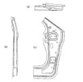
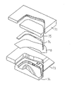


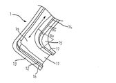
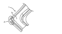
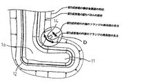
Classifications
-
- B—PERFORMING OPERATIONS; TRANSPORTING
- B21—MECHANICAL METAL-WORKING WITHOUT ESSENTIALLY REMOVING MATERIAL; PUNCHING METAL
- B21D—WORKING OR PROCESSING OF SHEET METAL OR METAL TUBES, RODS OR PROFILES WITHOUT ESSENTIALLY REMOVING MATERIAL; PUNCHING METAL
- B21D22/00—Shaping without cutting, by stamping, spinning, or deep-drawing
- B21D22/20—Deep-drawing
- B21D22/26—Deep-drawing for making peculiarly, e.g. irregularly, shaped articles
-
- B—PERFORMING OPERATIONS; TRANSPORTING
- B21—MECHANICAL METAL-WORKING WITHOUT ESSENTIALLY REMOVING MATERIAL; PUNCHING METAL
- B21D—WORKING OR PROCESSING OF SHEET METAL OR METAL TUBES, RODS OR PROFILES WITHOUT ESSENTIALLY REMOVING MATERIAL; PUNCHING METAL
- B21D22/00—Shaping without cutting, by stamping, spinning, or deep-drawing
- B21D22/20—Deep-drawing
- B21D22/22—Deep-drawing with devices for holding the edge of the blanks
-
- B—PERFORMING OPERATIONS; TRANSPORTING
- B21—MECHANICAL METAL-WORKING WITHOUT ESSENTIALLY REMOVING MATERIAL; PUNCHING METAL
- B21D—WORKING OR PROCESSING OF SHEET METAL OR METAL TUBES, RODS OR PROFILES WITHOUT ESSENTIALLY REMOVING MATERIAL; PUNCHING METAL
- B21D22/00—Shaping without cutting, by stamping, spinning, or deep-drawing
- B21D22/20—Deep-drawing
-
- B—PERFORMING OPERATIONS; TRANSPORTING
- B21—MECHANICAL METAL-WORKING WITHOUT ESSENTIALLY REMOVING MATERIAL; PUNCHING METAL
- B21D—WORKING OR PROCESSING OF SHEET METAL OR METAL TUBES, RODS OR PROFILES WITHOUT ESSENTIALLY REMOVING MATERIAL; PUNCHING METAL
- B21D24/00—Special deep-drawing arrangements in, or in connection with, presses
- B21D24/04—Blank holders; Mounting means therefor
-
- B—PERFORMING OPERATIONS; TRANSPORTING
- B21—MECHANICAL METAL-WORKING WITHOUT ESSENTIALLY REMOVING MATERIAL; PUNCHING METAL
- B21D—WORKING OR PROCESSING OF SHEET METAL OR METAL TUBES, RODS OR PROFILES WITHOUT ESSENTIALLY REMOVING MATERIAL; PUNCHING METAL
- B21D24/00—Special deep-drawing arrangements in, or in connection with, presses
- B21D24/10—Devices controlling or operating blank holders independently, or in conjunction with dies
- B21D24/12—Devices controlling or operating blank holders independently, or in conjunction with dies mechanically
-
- B—PERFORMING OPERATIONS; TRANSPORTING
- B21—MECHANICAL METAL-WORKING WITHOUT ESSENTIALLY REMOVING MATERIAL; PUNCHING METAL
- B21D—WORKING OR PROCESSING OF SHEET METAL OR METAL TUBES, RODS OR PROFILES WITHOUT ESSENTIALLY REMOVING MATERIAL; PUNCHING METAL
- B21D25/00—Working sheet metal of limited length by stretching, e.g. for straightening
- B21D25/04—Clamping arrangements
-
- B—PERFORMING OPERATIONS; TRANSPORTING
- B21—MECHANICAL METAL-WORKING WITHOUT ESSENTIALLY REMOVING MATERIAL; PUNCHING METAL
- B21D—WORKING OR PROCESSING OF SHEET METAL OR METAL TUBES, RODS OR PROFILES WITHOUT ESSENTIALLY REMOVING MATERIAL; PUNCHING METAL
- B21D5/00—Bending sheet metal along straight lines, e.g. to form simple curves
- B21D5/002—Positioning devices
-
- B—PERFORMING OPERATIONS; TRANSPORTING
- B21—MECHANICAL METAL-WORKING WITHOUT ESSENTIALLY REMOVING MATERIAL; PUNCHING METAL
- B21D—WORKING OR PROCESSING OF SHEET METAL OR METAL TUBES, RODS OR PROFILES WITHOUT ESSENTIALLY REMOVING MATERIAL; PUNCHING METAL
- B21D5/00—Bending sheet metal along straight lines, e.g. to form simple curves
- B21D5/04—Bending sheet metal along straight lines, e.g. to form simple curves on brakes making use of clamping means on one side of the work
-
- B—PERFORMING OPERATIONS; TRANSPORTING
- B21—MECHANICAL METAL-WORKING WITHOUT ESSENTIALLY REMOVING MATERIAL; PUNCHING METAL
- B21D—WORKING OR PROCESSING OF SHEET METAL OR METAL TUBES, RODS OR PROFILES WITHOUT ESSENTIALLY REMOVING MATERIAL; PUNCHING METAL
- B21D5/00—Bending sheet metal along straight lines, e.g. to form simple curves
- B21D5/06—Bending sheet metal along straight lines, e.g. to form simple curves by drawing procedure making use of dies or forming-rollers, e.g. making profiles
-
- B—PERFORMING OPERATIONS; TRANSPORTING
- B21—MECHANICAL METAL-WORKING WITHOUT ESSENTIALLY REMOVING MATERIAL; PUNCHING METAL
- B21D—WORKING OR PROCESSING OF SHEET METAL OR METAL TUBES, RODS OR PROFILES WITHOUT ESSENTIALLY REMOVING MATERIAL; PUNCHING METAL
- B21D53/00—Making other particular articles
- B21D53/88—Making other particular articles other parts for vehicles, e.g. cowlings, mudguards
Definitions
- the present invention relates to a method and an apparatus for manufacturing a pressed part. Specifically, the present invention relates to a manufacturing method and a manufacturing apparatus for a pressed part that has a hat cross section and has a curved portion that is curved in a longitudinal direction in a plan view so that the L-shaped shape is partly or entirely.
- An automobile body is composed of a plurality of skeleton members obtained by press forming a blank (in the following description, the case where the blank is a steel plate is taken as an example).
- These skeletal parts are extremely important parts in order to ensure automobile crash safety.
- side sills, cross members, front pillars, and the like are known as skeleton members.
- the hat cross section includes a top plate, two vertical walls, two concave ridge lines, and two flanges.
- Two vertical walls connect to both sides of the top board.
- Two concave ridge lines are connected to two vertical walls, respectively.
- the two flanges are respectively connected to the two concave ridge lines.
- Higher strength is required for the skeletal member in order to improve collision safety performance and reduce the weight of the vehicle body.
- FIG. 16 is a perspective view showing an example (for example, a side sill) of a skeleton member 0 having a hat cross section and having a shape straight in the longitudinal direction in a plan view and a side view.
- FIGS. 17A and 17B are explanatory diagrams of the front pillar 0-1 as an example of a skeleton member having a hat cross section, in which FIG. 17A is a perspective view and FIG. 17B is a plan view.
- FIG. 18 is a perspective view showing a part 1 (also referred to as “L-type press part” in this specification) 1 having an L shape by having a hat section and a curved portion that curves in the longitudinal direction in plan view.
- FIG. 1 also referred to as “L-type press part” in this specification
- a skeletal member in a plan view means that a skeletal member is viewed from a direction orthogonal to the top plate which is the widest planar portion of the member. Specifically, in FIG. 17A, this means that the skeleton member 0-1 is seen from the direction of the white arrow, and in FIG. 17B, the skeleton member 0-1 is seen from the direction orthogonal to the paper surface. Means.
- the skeleton member 0 illustrated in FIG. 16 has a substantially straight shape in the longitudinal direction.
- the front pillar 0-1 has an L shape by having a curved portion that curves in the longitudinal direction in plan view.
- the front pillar 0-1 has a hat cross section at the lower part 0-2 and includes a shape curved in an L shape in the longitudinal direction in plan view.
- the front pillar 0-1 includes a top plate 11, two vertical walls 12 and 14 connected to both sides of the top plate 11, and two concave ridge lines 16 and 17 connected to the two vertical walls 12 and 14, respectively.
- a hat-shaped cross section composed of two flanges 13 and 15 connected to the two concave ridge lines 16 and 17, respectively.
- the front pillar 0-1 has a curved portion 1a that is curved in the longitudinal direction, thereby partially having a shape curved in an L shape in plan view.
- the skeletal member 0 Since the skeletal member 0 has a substantially straight shape in the longitudinal direction, it can be manufactured mainly by bending a blank. In the skeleton member 0, the circumferential length of the cross section does not change greatly in the longitudinal direction. For this reason, even if the skeleton member 0 is made of a high-strength steel plate having low extensibility, cracks and wrinkles are hardly generated during press working, and it is relatively easy to form.
- Patent Document 1 discloses a method of bending a press part having a hat cross section. The method disclosed by Patent Document 1 manufactures a pressed part having a hat cross section but having a substantially straight shape in the longitudinal direction.
- FIG. 19 is a perspective view showing an L-shaped press part 1 manufactured by bending.
- the L-shaped press part 1 shown in FIG. 18 is bent by the method disclosed in Patent Document 1, wrinkles are generated in the outer flange portion (A portion) of the curved portion 1a as shown in FIG. For this reason, the L-shaped press part 1 is generally formed by press forming by drawing.
- draw forming a blank is formed using a blank holder in addition to a die and a punch in order to control the amount of inflow of the blank and suppress the generation of wrinkles.
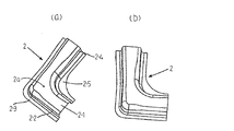
- FIGS. 20A and 20B are explanatory views showing the L-shaped press part 2, in which FIG. 20A is a perspective view and FIG. 20B is a plan view.
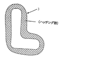
- FIG. 21 is a plan view showing the shape of the blank 3 and the wrinkle holding area B in the blank 3 in the case of drawing.
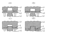
- FIGS. 22A to 22D are cross-sectional views showing the structure of a die for drawing and the drawing process.
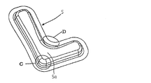
- FIG. 23 is a perspective view of the drawn panel 5 that has been drawn.
- a die 41, a punch 42 and a blank holder 43 are used as shown in FIGS. 22 (a) to 22 (d).
- the blank 3 is disposed between the punch 42 and the blank holder 43 and the die 41.
- the wrinkle holding region B (hatched portion in FIG. 21) around the blank 3 is firmly held by being sandwiched between the blank holder 43 and the die 41.
- the die 41 is relatively moved in the direction of the punch 42.
- the blank 3 is finally pressed against the punch 42 with the die 41 to process the blank 3. In this way, the diaphragm panel 5 shown in FIG. 23 is formed.
- the wrinkle holding region B around the blank 3 is sandwiched between the blank holder 43 and the die 41 and strongly held. For this reason, the area
- the diaphragm panel 5 can be molded while suppressing the generation of wrinkles.
- the molded diaphragm panel 5 is cut off unnecessary portions around the diaphragm panel 5, and the L-shaped press part 2 shown in FIGS. 20 (a) and 20 (b) is manufactured.
- the complicated shape of the L-shaped press part 2 can be formed.
- the vertical walls 2-2 and 2-4 shown in FIG. 20A are simultaneously formed. For this reason, a portion of the blank 3 formed on the top plate 2-1 does not flow much in the forming process, and the vertical walls 2-2, 2-4 as shown in FIGS. 22 (b) to 22 (d). Is formed by the blank 3 flowing from both sides of the top plate 2-1.
- the flange (D portion in FIG. 23) inside the curved portion 5a that curves in an L shape in plan view in the diaphragm panel 5 is in a molding state called so-called stretch flange molding.
- a high-strength steel sheet having a tensile strength of 590 MPa or more cannot be processed without cracking at the D portion because the elongation is small.
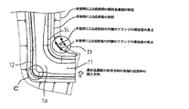
- FIG. 24 is a plan view for explaining the inflow of material in the drawing.
- the outer vertical wall 12 and the inner vertical wall 14 of the curved portion 1a are simultaneously formed. For this reason, the blank 3 of the part shape
- the blank 3 of the portion (D portion in FIGS. 23 and 24) formed inside the bending portion 1a moves from the inside to the outside of the bending portion 1a and is greatly stretched in the radial direction of the bending portion 1a.
- This is a molding state called “stretch flange molding”. For this reason, cracks occur in high-strength steel sheets with low extensibility.
- the C portion in FIG. 23 has a shape that protrudes outward at the outer corner of the curved portion 1a, and thus the blank 3 is greatly extended. As a result, cracks occur in the high-strength steel sheet having low extensibility in the C part as in the D part.
- a blank 3 made of a high-strength steel sheet having low extensibility, in particular, a high-strength steel sheet having a tensile strength of 590 MPa or more cannot be used as the material of the L-shaped press part 2 and has excellent extensibility.
- a relatively low strength steel plate was used for blank 3. For this reason, in order to ensure the predetermined strength, the thickness of the blank 3 has to be increased, which is against the request for weight reduction of the vehicle body.
- an L-shaped press part 1 is manufactured through the following first to third steps.
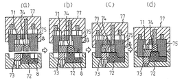
- Second step After the first step, by moving the bending die 75 relatively in the direction in which the punch 72 is arranged to process the blank 8, the vertical wall 14 inside the curved portion 1a, The concave ridge line 17 and the flange 15 are formed (see FIG. 1C).
- the die 71 and the blank holder 73 are moved in the direction in which the blank holder 73 is disposed with respect to the blank 8.
- the vertical wall 12 By moving relatively and processing the blank 8, the vertical wall 12, the concave ridge line 16 and the flange 13 on the outer side of the curved portion 1a are formed (see FIG. 1D).
- the molded press part 1 is taken out by raising the pad 74, the die 71, and the bending die 75 (see FIG. 1E).
- the vertical wall 14, the concave ridge line 17 and the flange 15 inside the curved portion 1 a are molded, but the vertical wall 12, the concave ridge line 16 and the flange 13 outside the curved portion 1 a are not molded. Therefore, the blank 8 being molded is pulled only from the inside of the curved portion 1a, and the portion of the blank 8 that is molded on the top plate 11 flows into the curved portion 1a.
- the portion of the blank 8 that is molded inside the curved portion 1a does not move so much from the inside to the outside of the curved portion 1a during the molding process. .
- the flange 15 inside the curved portion 1a is in a compressed state. For this reason, the amount of elongation of the flange 15 inside the curved portion 1a during molding is greatly reduced as compared with drawing.
- the concave ridge line 17 and the flange 15 inside the curved portion 1a, the portion molded on the top plate 11 and the portion molded on the flange 13 also flow into the curved portion 1a. It shrinks in the longitudinal direction and remains in a compressive stress state.
- the corner portion which is the meeting portion between the vertical wall 12 outside the curved portion 1a and the top plate 11 is also molded from the state where the compressive stress remains. Thereby, the required elongation of the blank is small compared with the drawing formed from a state without compressive stress.
- a high strength metal plate for example, a high strength steel plate having a tensile strength of 590 MPa or more
- the flange 15 inside the curved portion 1a and the vertical wall 12 and the top plate outside the curved portion 1a. 11 can suppress the elongation of the blank 8 at the corner portion, which is a meeting portion with the portion 11, to be small. For this reason, even if it uses the high intensity
- the vertical wall 14, the concave ridge line 17 and the flange 15 inside the curved portion 1 a are bent by a bending die 75 and a punch 72. For this reason, it is not necessary to provide a wrinkle holding region that is always provided in the drawing by a portion formed inside the curved portion 1a or at the tip portion in the longitudinal direction.
- the blank 8 can be reduced by this amount, and the yield of the material can be increased.
- JP 2006-015404 A Japanese Unexamined Patent Publication No. 64-66024 International Publication No. 2014/106932 Pamphlet
- the blank 8 is made of an ultra-high tensile steel plate having a tensile strength of 1180 MPa or more, the height of the L-shaped press part 1 is 55 mm or more, and the radii of curvature of the concave ridge lines 16 and 17 of the L-shaped press part 1 Even when at least two of R 1 is 15 mm or less or the radius of curvature R 2 inside the curved portion 1 a in the L-shaped press part 1 is 140 mm or less are satisfied, according to Patent Document 3. In the disclosed second step, the flange 15 inside the curved portion 1a is cracked.
- the present invention was made to increase the molding limit of the invention disclosed in Patent Document 3 and to solve a new problem in the second step of Patent Document 3.
- the present invention corresponds to any one of the above (a) to (e)
- the L-shape can be obtained without causing cracks in the flange 15 inside the curved portion 1a even if the pressing process in the second step is performed. It aims at providing the manufacturing method and manufacturing apparatus which can manufacture the press component 1.
- the limit amount of the blank 8 that can flow into the portion formed in the vertical wall 14 inside the curved portion 1a is the cross-sectional circumference of the flange 15 before and after forming the cross section in the inflow direction of the blank 8. It is determined geometrically by the amount of change in length. This limit amount becomes the molding limit of the second step of molding the vertical wall 14 inside the curved portion 1a.
- Second step After the first step, the bending die is moved in the direction in which the punch is disposed, and the blank is subjected to press working by bending, so that the inside of the bending portion A vertical wall, a concave ridge line connected to the vertical wall, and a flange connected to the concave ridge line are formed.
- Third step After the second step, with the blank held between the blank holder and the die, the die and the blank holder are relatively moved in the direction in which the punch is disposed. Then, by pressing the blank by drawing, a vertical wall outside the curved portion, a concave ridge line connected to the vertical wall, and a flange connected to the concave ridge line are formed.
- one or more material inflow promoting portions are formed side by side in a portion of the blank that is formed on the flange inside the curved portion of the pressed part.
- the material inflow promoting portion increases the amount of the blank flowing into the portion formed on the flange inside the curved portion.
- the material inflow promoting portion has a cross-sectional circumferential length in a cross section along a direction parallel to a straight line in contact with a central position inside the curved portion and perpendicular to the top plate in a plan view orthogonal to the top plate.
- the cross-sectional shape increases as the distance from the inner flange of the curved portion increases.
- the blank is made of an ultra-high tensile steel plate having a tensile strength of 1180 MPa or more, the projection distance of the vertical wall, which is the height of the press part, in the product height direction is 70 mm or more, the press part Satisfying at least one of a curvature radius of the concave ridge line of 10 mm or less in a side view or a curvature radius inside the curved portion of the pressed part of 100 mm or less in the plan view. .
- the blank is made of an ultra-high tensile steel plate having a tensile strength of 1180 MPa or more, the projection distance of the vertical wall, which is the height of the press part, in the product height direction is 55 mm or more, the press part Satisfying at least two of the following: the curvature radius of the concave ridge line is 15 mm or less in a side view, or the curvature radius inside the curved portion of the pressed part is 140 mm or less in the plan view. To do.
- the material inflow promoting portion is a convex bead that protrudes in a direction from the flange toward the top plate in a direction in which the flange and the top plate are arranged, or a direction in which the flange and the top plate are arranged 5.
- the material inflow promoting portion has a vertical cross section including a straight line in contact with a central position inside the curved portion and a straight line orthogonal to the horizontal plane at the end of the second step, and
- the punch has a shape including a top plate, a vertical wall located inside the curved portion, a concave ridge line connected to the vertical wall, and a shape on the plate thickness back side of each flange connected to the concave ridge line
- the blank holder has a shape including a concave ridge line connected to the vertical wall located outside the curved portion and a shape on the plate thickness back side of the flange connected to the concave ridge line
- the pad has a shape including the shape of the top surface side of the top plate so as to face the blank holder
- the die has a shape including a vertical wall located outside the curved portion, a concave ridge line connected to the vertical wall, and a shape on the plate thickness surface side of each flange connected to the concave ridge line;
- Each of the bending dies desirably has a shape including a vertical wall located inside the curved portion, a concave ridge line connected to the vertical wall, and
- the blank may be a pre-processed metal plate.
- the blank holder is fixed so as not to move relative to the punch, and the press part formed with the blank holder
- the press part may be taken out of the die by pressing the squeeze against the die so that no pressure is applied and the pad, the die and the bending die are relatively separated from the blank holder and the punch.
- the blank has a plate thickness of 0.8 mm or more and 3.2 mm or less.
- the width of the top plate is 30 mm or more and 400 mm or less in plan view, and the projection distance of the vertical wall, which is the height of the press part, in the product height direction is 300 mm or less.
- the radius of curvature inside the curved portion of the pressed part is 5 mm or more in plan view.
- a punch and a blank holder, and a pad, a die, and a bending die that are arranged to face the punch and the blank holder are provided.
- a top plate extending in the direction, two vertical walls connected to both sides of the top plate, two concave ridge lines connected to the two vertical walls, and two flanges connected to the two concave ridge lines, respectively.
- a press for producing a pressed part having a L-shaped shape partly or entirely in the plan view by having a hat-shaped cross section and a curved portion curved in the longitudinal direction in a plan view perpendicular to the top plate A device for manufacturing parts, An apparatus for manufacturing a pressed part that satisfies the following conditions 1 and 2; 1st process: While holding the said pad on both sides of the part shape
- Second step After the first step, the bending die moves relative to a direction in which the punch is arranged to process the blank, thereby forming a vertical wall on the inner side of the curved portion.
- the concave ridge line connected to the vertical wall and the flange connected to the concave ridge line are formed.
- Third step After the second step, the blank holder is held with the die sandwiched with the blank, and the die and the blank holder are arranged with respect to the blank holder.
- the press part is formed by forming the vertical wall on the outside of the curved portion, the concave ridge line connected to the vertical wall, and the flange connected to the concave ridge line by processing the blank by moving relatively in the direction of Is molded.
- the bending die and the punch have one or more material inflow promoting portions arranged side by side with the portion formed on the flange inside the curved portion of the pressed part in the blank in the second step.
- a material inflow promoting portion forming mechanism is provided. However, the material inflow promoting portion increases the amount of the blank flowing into the portion formed on the flange inside the curved portion.
- the material inflow promoting portion forming mechanism is configured such that the material inflow promoting portion is parallel to a straight line in contact with a central position of the inner periphery of the curved portion and orthogonal to the top plate in a plan view orthogonal to the top plate.
- the circumferential length of the cross section in the cross section along the direction to be increased is formed so as to increase as the distance from the inner flange of the curved portion of the press part increases.
- the press part manufacturing apparatus according to item 9, further satisfying the following condition 3 or 4.
- the blank is made of an ultra-high tensile steel plate having a tensile strength of 1180 MPa or more, the projection distance of the vertical wall, which is the height of the press part, in the product height direction is 70 mm or more, the press part Satisfying at least one of a curvature radius of the concave ridge line of 10 mm or less in a side view or a curvature radius inside the curved portion of the pressed part of 100 mm or less in the plan view. .
- the blank is made of an ultra-high tensile steel plate having a tensile strength of 1180 MPa or more, the projection distance of the vertical wall, which is the height of the press part, in the product height direction is 55 mm or more, the press part Satisfying at least two of the following: the curvature radius of the concave ridge line is 15 mm or less in a side view, or the curvature radius inside the curved portion of the pressed part is 140 mm or less in the plan view. To do.
- the material inflow promoting portion is a convex bead that protrudes in a direction from the flange toward the top plate in a direction in which the flange and the top plate are arranged, or a direction in which the flange and the top plate are arranged 13.
- the material inflow promoting portion forming mechanism includes a vertical cross section including the material inflow promoting portion including a straight line that is orthogonal to a straight line in contact with a central position inside the curved portion at the end of the second step.
- the blank is formed so as to have an outer shape obtained by connecting a portion formed at the concave ridge line inside the curved portion and the meeting point of the flange and an edge of the blank.
- the device for manufacturing a pressed part according to any one of 9 to 16, comprising an apparatus for performing the following fourth step after the third step: 4th process;
- surroundings of the molded article obtained by the said 3rd process is removed.
- the press part manufacturing apparatus it is desirable to include a lock mechanism for fixing the blank holder so as not to move relative to the punch when releasing after completion of molding.
- a sub-base configured to support the pad and the die so as to be movable up and down, and to be integrated with the bending die, and a die base that supports the sub-base so as to freely enter and exit.
- the die is supported so as to be movable up and down
- the sub-base is configured integrally with the bending die
- the die base is supported so that the pad can be moved up and down and the sub-base is supported freely. It is desirable to have
- the inflow amount of the material is increased as compared with the invention disclosed in Patent Document 3 and the molding limit is increased.
- the L-shaped press part can be manufactured with good yield without causing cracks in the flange inside the curved portion.
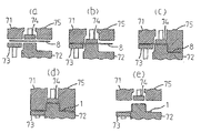
- FIG. 1A to FIG. 1E are cross-sectional views showing the outline of the configuration of the manufacturing apparatus and the molding process according to the embodiment of the present invention.
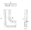
- 2 (a) to 2 (e) are cross-sectional views showing a configuration example of another mold and a molding process according to the embodiment of the present invention.
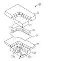
- FIG. 2A is an explanatory diagram partially showing a configuration example of a manufacturing apparatus according to an embodiment of the present invention.
- FIG. 2B is an explanatory view partially showing an example of a second step of forming the vertical wall inside the curved portion of the intermediate molded product press-molded by the manufacturing apparatus according to the embodiment of the present invention.
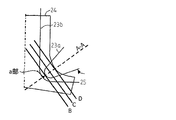
- FIG. 2C is an explanatory diagram showing a positional relationship between the blank and the material inflow promoting portion forming mechanism and the concave ridge line forming portion in the manufacturing apparatus according to the embodiment of the present invention.
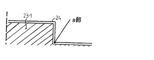
- FIG. 2D is an explanatory view showing a cross section corresponding to the AA cross section of FIG. 2A in a conventional punch without a material inflow promoting portion forming mechanism.
- FIG. 2E is an explanatory diagram showing the positional relationship between the material inflow promoting portion forming mechanism and the concave ridge line forming portion and the blank and the positions of the B, C, and D cross sections in the manufacturing apparatus according to the embodiment of the present invention.
- FIG. 2F is a graph showing a cross-sectional peripheral length difference with respect to a conventional punch at a flange forming portion of the punch in B, C, and D cross-sections.
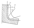
- FIG. 2G is an explanatory view showing an AA cross section of a punch provided with a material inflow promoting portion forming mechanism.
- FIG. 2H is an explanatory diagram showing the positional relationship between the material inflow promoting portion forming mechanism and the concave ridge line forming portion and the blank and the positions of the B, C, and D sections in the manufacturing apparatus according to the embodiment of the present invention.
- FIG. 2I is an explanatory diagram showing the reason why cracking at the part a of the blank is prevented by providing the bending mold and the punch with a material inflow promoting portion forming mechanism constituted by a concave portion and a convex portion.
- FIG. 2J (a) to FIG. 2J (f) are explanatory views showing examples of shapes of components of various material inflow promoting portion forming mechanisms formed on the punch.
- FIG. 3A is a plan view showing the shape of the blank before molding
- FIG. 3B is a plan view showing the shape of the blank in the molding process.
- FIG. 4 is a plan view showing a material flow in the embodiment of the present invention.
- FIG. 5 (d) are explanatory views showing an example of a mold used in the present invention.
- 6 (a) to 6 (d) are explanatory views showing another example of the mold used in the present invention.
- FIGS. 7A to 7D are explanatory views showing another example of the mold used in the present invention.
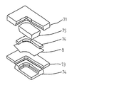
- FIG. 8 is an exploded perspective view of the mold shown in FIG. 9 (a) to 9 (c) are a front view, a plan view, and a right side view, respectively, showing press parts to be molded in Comparative Examples 1 to 7 and Invention Examples 1 to 7.
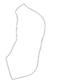
- FIG. 10 is a plan view showing the shape of the blank used in Comparative Examples 1-7 and Invention Examples 1-7.
- FIG. 11 is a perspective view showing the configuration of the mold used in Comparative Examples 1-7.
- FIG. 12 is a plan view showing the shape of the blank used in Examples 8 and 9 of the present invention.
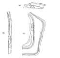
- FIGS. 13 (a) to 13 (c) are a front view, a right side view, and a plan view, respectively, showing the shapes of the intermediate molded products formed in Examples 8 and 9 of the present invention.
- 14 (a) to 14 (c) are a front view, a right side view, and a plan view, respectively, showing the shapes of the pressed parts formed in Examples 8 and 9 of the present invention.
- FIG. 15 is a perspective view showing a configuration of a mold for performing molding according to the present invention in Examples 8 and 9 of the present invention.
- FIG. 13 (a) to 13 (c) are a front view, a right side view, and a plan view, respectively, showing the shapes of the pressed parts formed in Examples 8 and 9 of the present invention.
- FIG. 15 is a perspective view showing a configuration of a mold for performing molding according to the present invention in Examples 8 and 9 of the present invention.
- FIG. 16 is a perspective view of an example of a skeleton member having a hat cross section and having a straight shape in the longitudinal direction in a plan view and a side view.
- FIG. 17 is an explanatory view of a front pillar that is a skeleton member having a hat cross section, in which FIG. 17 (a) is a perspective view and FIG. 17 (b) is a plan view.
- FIG. 18 is a perspective view showing an L-shaped press part.
- FIG. 19 is a perspective view showing an L-shaped press part manufactured by bending.
- 20A and 20B are explanatory views showing an L-shaped press part.
- FIG. 20A is a perspective view and FIG. 20B is a plan view.
- FIG. 20A is a perspective view and FIG. 20B is a plan view.
- FIG. 21 is a plan view showing the shape of the blank in the case of drawing and the wrinkle holding area in the blank.
- FIGS. 22A to 22D are cross-sectional views showing the structure of a die for drawing and the drawing process.
- FIG. 23 is a perspective view of a drawn diaphragm panel.
- FIG. 24 is a plan view for explaining the inflow of material in the drawing.
- L-shaped press part 1 As exemplified in FIG. 18, the L-shaped press part 1 has a hat cross section and a curved portion 1 a curved in an L shape in the longitudinal direction in a plan view.
- the hat cross section is composed of a top plate 11, vertical walls 12 and 14, concave ridges 16 and 17, and flanges 13 and 15.
- the vertical walls 12 and 14 are connected to both sides of the top plate 11.
- the concave ridge lines 16 and 17 are connected to the vertical walls 12 and 14, respectively.
- the flanges 13 and 15 are connected to the concave ridge lines 16 and 17, respectively.
- the L-shaped press part 1 has an L-shaped shape in plan view by having the curved portion 1a.
- the L-shaped press part 1 is made of a blank made of a high-tensile steel plate having a plate thickness of 0.8 mm or more and 3.2 mm or less and a tensile strength of 590 MPa or more, particularly 1180 MPa or more and 1800 MPa or less.
- This high-tensile steel plate is generally used as a skeleton member for automobiles.
- the tensile strength of the blank is 200 MPa or more, preferably 1800 MPa or less in order to ensure performance such as strength as a skeleton member for automobiles.
- the tensile strength of the blank is 500 MPa or more, preferably 590 MPa or more, and more preferably 1180 MPa or more, the thickness of the blank can be reduced, and the L-shaped press part 1 can be reduced in weight.
- the width of the top plate 11 in a plan view is desirably 400 mm or less.
- the pressurizing device for the pad 74 such as a gas cushion must be made small, so that the pressure applied to the pad 74 cannot be secured.
- the width of the top plate 11 is desirably 30 mm or more.
- the vertical wall 12, 14, which is the height of the vertical walls 12, 14 in a side view, is projected too far in the product height direction, the vertical wall 14, the concave ridge line 17, and the flange portion 15 inside the curved portion 1 a.
- the inflow resistance of the blank 8 is increased when the is molded, and the inflow of the blank 8 to the inside of the curved portion 1a becomes insufficient.
- the height of the vertical walls 12 and 14 is desirably 300 mm or less.
- the height of the vertical walls 12 and 14 is desirably 70 mm or more. This is because when the height of the vertical walls 12 and 14 is less than 70 mm, the L-shaped press part 1 can be molded without causing cracks in the flange 15 by the molding method disclosed in Patent Document 3 regardless of the present invention. .
- the radius of curvature of the concave ridgelines 16 and 17 of the L-shaped press part 1 is too small, the flow of the blank 8 into the inside of the curved portion 1a becomes insufficient when the flange portion 15 inside the curved portion 1a is formed. . For this reason, it is desirable that the radius of curvature of the concave ridge lines 16 and 17 is 5 mm or more in a side view.
- the radius of curvature of the vertical wall 14 inside the curved portion 1a in plan view is 100 mm or less. This is because when the radius of curvature exceeds 100 mm, the L-shaped press part 1 can be molded without causing the flange 15 to crack by the molding method disclosed in Patent Document 3 without depending on the present invention.
- the curvature radii of the concave ridge lines 16 and 17 are desirably 10 mm or less. This is because if the radius of curvature of the concave ridge line 17 is greater than 10 mm, the L-shaped press part 1 can be molded without causing cracks in the flange 15 by the molding method disclosed in Patent Document 3 without depending on the present invention.
- the blank 8 is made of an ultra-high tensile steel plate having a tensile strength of 1180 MPa or more, the projection distance in the product height direction of the vertical walls 12 and 14 that are the height of the L-type press part 1 is 55 mm or more, and the L-type press At least one of the curvature radii of the concave ridge lines 16 and 17 of the part 1 being 15 mm or less in a side view, or the curvature radius inside the curved portion 1a in the L-shaped press part 1 being 140 mm or less in a plan view. It is desirable to satisfy two or more. This is because if any one or none of these is satisfied, the L-shaped press part 1 can be formed without cracking the flange 15 by the forming method disclosed in Patent Document 3 without depending on the present invention. .
- the plate thickness reduction rate of the L-shaped press part 1 ⁇ (plate thickness maximum value ⁇ plate thickness minimum value) / plate thickness maximum value ⁇ ⁇ 100 is 15% or less.
- the L-shaped press part 1 having such a low sheet thickness reduction rate has not existed so far.
- the plate thickness reduction rate of the L-shaped press part 1 which is a structural member of an automobile body is so low, a steel plate having a tensile strength of 200 MPa or more as a blank, preferably a high-tensile steel plate having a tensile strength of 590 MPa or more, more preferably
- the thickness of the blank can be reduced, and the weight of the L-shaped press part 1 having excellent collision safety performance can be reduced.
- the tensile strength of the L-shaped press part 1 is practically 1800 MPa or less.
- FIGS. 1A to 1E are cross-sectional views showing the outline of the configuration and forming process of a manufacturing apparatus according to an embodiment of the present invention.
- FIGS. 1 (a) to 1 (e) the mold shown in FIGS. 1 (a) to 1 (e) is used in order to press the blank 8 to form the L-shaped press part 1.
- FIG. This mold includes a punch 72 and a blank holder 73, and a pad 74, a die 71, and a bending die 75 that are disposed to face the punch 72 and the blank holder 73.
- the punch 72 has a shape including the shape of the plate thickness back side of each of the top plate 11 of the L-shaped press part 1, the vertical wall 14 inside the curved portion 1 a, the concave ridge line 17, and the flange 15.
- the blank holder 73 has a shape including the shape of the vertical wall 12 on the outer side of the curved portion 1 a, the concave ridge line 16, and the shape on the plate thickness back side of the flange 13.
- the pad 74 has a shape including the shape on the plate thickness surface side of the top plate 11 so as to face the blank holder 73.
- the die 71 has a shape including the shape on the plate thickness surface side of each of the vertical wall 12 and the flange 13 outside the curved portion 1a.
- the bending die 75 has a shape including the shape on the plate thickness surface side of each of the vertical wall 14, the concave ridge line 17 and the flange 15 inside the curved portion 1 a.
- 2 (a) to 2 (e) are cross-sectional views showing the structure and molding process of another mold according to the embodiment of the present invention. A difference from the mold shown in FIG. 1 is that a lock mechanism 76 described later is attached to the punch 72.
- the lock mechanism 76 is configured by a pin that is arranged so as to freely enter and exit the punch 72.
- the lock mechanism 76 is completely accommodated in the punch 72 from the start of molding to the bottom dead center of the molding (FIGS. 2A to 2C).
- the locking mechanism 76 moves and protrudes toward the blank holder 73 side at the molding bottom dead center shown in FIG. 2 (d), and fixes the blank holder 73 to the punch 72.
- the lock mechanism 76 raises the die 71, the pad 74, and the bending die 75 while releasing the mold while the blank holder 73 is fixed to the punch 72 at the time of releasing. In this way, the lock mechanism 76 prevents the molded L-shaped press part 1 from being damaged by the applied pressure of the pad 74.
- a mechanism may be used in which the pad 74, the bending die 75, and the die 71 (drawing die) are fixed (held) and released from the molding at the bottom dead center after the molding is completed.
- the pad 74 is fixed to the bending die 75, and at the same time, the die 71 (drawing die) is fixed to the pad 74 or the bending die 75 and released.
- B By releasing the spacer, the space between the blank holder 73 and the pad 74 at the bottom dead center is fixed and released.
- C It is exemplified that the pad 74 and the die 71 (drawing die) are released from the mold by fixing (holding) the positional relationship at the bottom dead center.
- the lock mechanism 76 can stop the rise of the blank holder 73 if it can be controlled on the main body side of the press machine, for example, the rise of the cushion pin on the press machine side connected to the blank holder 73. It does not have to be provided in a mold such as the punch 72.
- FIG. 2A is an explanatory diagram partially showing a configuration example of the manufacturing apparatus 20 according to the embodiment of the present invention.
- 2A to 2J the components of the mold and the blank are given different signs from those shown in FIGS. 1 and 2, but for convenience of explanation, the components of the mold and the blank are the same. Show things.
- the manufacturing apparatus 20 includes a bending die 21, a die 22, and a blank holder 27, and a punch 23 that is disposed to face the bending die 21 and the die 22.
- the manufacturing apparatus 20 applies a cold or warm to a blank 24 or a preformed blank (not shown) disposed between the die 22, the bending die 21 and the die pad 26, and the punch 23 and the blank holder 27.
- the L-shaped press part 1 having the outer shape shown in FIG. 18 or an intermediate molded product 1-1 thereof is manufactured by performing press working.
- the “intermediate molded product” means a press-molded product before removing a material inflow promoting portion described later.
- An L-shaped press-molded product can be obtained by removing unnecessary parts such as the material inflow promoting portion from the intermediate molded product.
- the manufacturing apparatus 20 is preferably used when the above condition 1 or 2 is satisfied.
- condition 1 or 2 if the second processing in Patent Document 3 is performed, the inner flange 15 of the curved portion 1a of the L-shaped press part 1 to be obtained is cracked, so the manufacturing apparatus 20 is used. This is because effectiveness is obtained.
- FIG. 2B is an explanatory view partially showing an example of the intermediate molded product 1-1 press-molded by the manufacturing apparatus 20.
- FIG. 2C is an explanatory diagram showing the positional relationship between the material inflow promoting portion forming mechanism 25 and the concave ridge line forming portion 23 b and the blank 24 in the manufacturing apparatus 20.
- the manufacturing apparatus 20 performs press working by bending in the second process disclosed in Patent Document 3, and further, as shown in FIGS. 2A and 2C, the bending die 21 and the punch 23 include a material inflow promoting portion.
- the forming mechanism 25 As the forming mechanism 25, a concave portion 21a and a convex portion 23a for forming the material inflow promoting portion 19 are formed in the blank 24, respectively.
- the material inflow promoting portion forming mechanism 25 includes the concave portion 21 a provided in the bending die 21 and the convex portion 23 a provided in the punch 23.
- the manufacturing apparatus 20 has a flange 24 on the inside of the curved portion 1 a of the L-shaped press part 1 in the blank 24 during the press working by bending in the second process disclosed in Patent Document 3.
- the material inflow promoting portion 19 is formed in the vicinity of the portion to be formed into the shape 15.
- the material inflow promoting portion forming mechanism 25 has the material inflow promoting portion 19 outside the region (hatching region in FIG. 2C) of the blank 24 that is molded into the L-shaped press part 1. It is desirable to form the region. Thereby, it becomes possible to leave no trace of the material inflow promoting portion 19 in the L-shaped press part 1.
- the material inflow promoting portion 19 is formed in the blank 24 in the region where the L-shaped pressed part 1 is formed (see FIG. It may be provided on the inner side of the hatching area in 2C.
- FIG. 2D is an explanatory view showing a cross section corresponding to the AA cross section of FIG. 2A in a conventional punch 23-1 in which the material inflow promoting portion forming mechanism 25 is not provided.
- FIG. 2E is an explanatory diagram showing the positional relationship between the material inflow promoting portion forming mechanism 25 and the concave ridge line forming portion 23b and the blank 24 in the manufacturing apparatus 20 and the positions of the B, C, and D cross sections.
- FIG. 2F is a graph showing a cross-sectional circumferential length difference with respect to the conventional punch at the flange forming portion of the punch 23 in the B, C, and D cross sections.
- the left side shows the case of the conventional method
- the right side shows the case of the embodiment of the present invention.
- 2F shows the shape of the blank 24 in the B, C, and D cross sections.
- FIG. 2G shows an AA cross section of the punch 23 provided with the material inflow promoting portion forming mechanism 25.
- the material inflow promoting portion forming mechanism 25 constituted by the concave portion 21a provided in the bending die 21 and the convex portion 23a provided in the punch 23. Then, the material inflow promoting portion 19 is formed in the press-molded intermediate molded article 1-1.
- the material inflow promoting portion 19 is formed so that the cross-sectional circumference in the B, C, and D cross sections gradually increases as the distance from the inner surface of the curved portion 1a increases.
- the B, C, and D cross sections are the center in the curved circumferential direction inside the curved portion 1a in plan view perpendicular to the top plate 11 as the distance from the flange 15 inside the curved portion 1a of the L-shaped press part 1 increases.
- a cross section along a direction parallel to a straight line in contact with the position (a section) and perpendicular to the top plate material inflow direction cross section: maximum main strain direction cross section of the deformation of the flange 15 inside the curved portion 1a of the L-shaped press part 1 ).
- the center position is not limited to a strict center position, and may be in a predetermined region including the strict center position in the curved circumferential direction.
- the cross-sectional shape of the material inflow promoting portion 19 is not limited to a shape that monotonously increases as the distance from the flange 15 inside the curved portion 1a of the L-shaped press part 1 is increased. Also good.
- the conventional punch in the flange forming portion of the punch 23 in the B, C, D cross section As shown in FIG. 2F, in the embodiment of the present invention, compared with the conventional method in which the material inflow promoting portion forming mechanism 25 is not provided, the conventional punch in the flange forming portion of the punch 23 in the B, C, D cross section. The difference in the cross-sectional circumference with respect to is increased.
- the material inflow promoting portion forming mechanism 25 is configured such that the cross-sectional circumferential length difference in the C cross section is larger than the cross-sectional circumferential length difference in the B cross section, and the cross-sectional circumferential length difference in the D cross section is C cross section. It is provided so as to be larger than the difference in cross-sectional circumference.
- the material inflow facilitating portion forming mechanism 25 having a shape that has a cross-sectional line length difference (inflow amount) that increases the cross-sectional line length difference (inflow amount) of the B, C, and D cross-sections,
- the punch 23 is provided as a concave portion 21a and a convex portion 23a.
- the material inflow accelerating portion 19 is formed in the blank 24 in a vertical cross section including a straight line in contact with the central position inside the curved portion 1a at the end of the second step and a straight line orthogonal to the horizontal plane. It is exemplified that it is formed so as to have an outer shape obtained by connecting a portion formed at the meeting point of the concave ridge line 17 inside the curved portion 1 a and the flange 15 and the edge portion 24 a of the blank 24.
- FIG. 2H is an explanatory diagram showing the positional relationship between the material inflow promoting portion forming mechanism 25 and the concave ridge line forming portion 23b and the blank 24 in the manufacturing apparatus 20 and the positions of the B, C, and D cross sections.
- the difference in change in the inflow amount of material by the material inflow promoting portion forming mechanism 25 (inflow increase amount in FIG. 2F (inflow by the method of the present invention with respect to the inflow amount by the conventional method without providing the material inflow promoting portion forming mechanism) Means an increase in the amount) as the distance from the part a of the blank 24 increases as shown by a thick arrow in FIG. 2H (B cross section ⁇ C cross section ⁇ D cross section).
- the change difference in the a part of the blank 24 becomes easy to produce a crack more, it is almost unnecessary to provide.
- what is necessary is just to let the area
- FIG. 2I shows the reason why cracking at a part of the blank 24 is prevented by providing the bending die 21 and the punch 23 with the material inflow promoting part forming mechanism 25 constituted by the concave part 21a and the convex part 23a.
- the cause of the crack in the a part of the blank 24 is the high tension F in the circumferential direction of the concave ridge line 17 located in the upper part of the a part in the blank 24.
- the material inflow promoting portion forming mechanism 25 is provided to perform press working, thereby increasing the amount of material inflow outside the portion a. Thereby, since the inflow amount of the material from the circumference
- the material inflow promoting portion forming mechanism 25 increases the amount of material flowing into the portion of the blank 24 that is molded into the curved portion 1a. For this reason, although the principal stress direction of the deformation of this portion does not change greatly, the deformation amount of this portion is reduced.
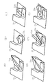
- FIGS. 2J (a) to 2J (f) are explanatory views showing examples of shapes of components of various material inflow promoting portion forming mechanisms 25 formed on the punch 23.
- FIG. 2J (a) As the convex portion 23a that is a component of the material inflow promoting portion forming mechanism 25 provided in the punch 23, as shown in FIG. 2J (a), the top plate 11 in the L-shaped press part 1 described with reference to FIG. A convex portion that is convex toward the same side can be used.
- a concave portion 23c that protrudes toward the side opposite to the top plate 11 of the L-shaped press part 1 may be used. In this case, it goes without saying that a convex portion corresponding to the concave portion 23 c is formed in the bending die 21.
- the convex portion 23a may be formed in a range where the blank 24 contacts.
- the material inflow promoting portion 19 is in the blank 24.
- the convex portion 23a may be formed so as to be provided on the inner side of the region (hatched region in FIG. 2C) formed in the L-shaped press part 1.
- two or more convex portions 23a may be provided. Further, as shown in FIG. 2J (f), the convex portion 23a may be formed in a step shape in a direction parallel to the plate thickness direction of the blank 12.
- the material inflow promoting portion forming mechanism 25 is located inside the curved portion 1a of the L-shaped press part 11 in the blank 24 at the portion formed in the longitudinal end 1b of the L-shaped press part 1 in the blank 24.
- One or more material inflow facilitating portions 19 that increase the amount of material inflow into the portion formed in the flange 15 are formed.
- the convex portions 23a and the concave portions 23c are drawn so as to have an edge in order to clarify the constituent elements. Needless to say, the edges of the convex portions 23a and the concave portions 23c are smooth R (curved).
- the L-shaped press part 1 to be manufactured by the embodiment of the present invention satisfies the above-described condition 1 or 2, and the conventional method described in Patent Document 3 causes a crack at the part a.
- FIG. 3A is a plan view showing the shape of the blank 8 before molding
- FIG. 3B is a plan view showing the shape of the blank 8 in the molding process
- FIG. 4 is a plan view showing a material flow in the embodiment of the present invention. 3 and 4, the material inflow promoting portion 19 and the material inflow promoting portion forming mechanism 25 are omitted.
- the blank 8 having the shape shown in FIG. 3A is disposed between the punch 72 and the blank holder 73, the pad 74, the die 71, and the bending die 75.
- the portion formed on the top plate 11 in the blank 8 is sandwiched and pressed between the pad 74 and the punch 72, and is formed on the top plate 11 in the blank 8.
- a portion that is outside the curved portion 1 a is pressed and held between the blank holder 73 and the die 71.
- the bending die 75 is moved relatively in the direction in which the punch 72 is disposed to process the blank 8, and the vertical wall 14 and the concave ridge line inside the curved portion 1a are processed.
- the blank 8 is formed into the shape shown in FIG.
- the portion sandwiched between the punch 72, the blank holder 73, the pad 74, and the die 71 also flows into the inner peripheral side of the curved portion 1a and is molded.
- the blank 8 is sandwiched between the blank holder 73 and the die 71 and pressed. While holding, the die 71 and the blank holder 73 are moved relative to the blank 8 in the direction in which the blank holder 73 is arranged, the blank 8 is processed, and the vertical wall 12 on the outer side of the curved portion 1a is recessed. The ridgeline 16 and the flange 13 are formed. In this way, the L-shaped press part 1 shown in FIG. 18 is formed.
- the extensibility of the required material becomes smaller than in the case of drawing forming from a state without compressive stress.
- a high-strength material having low elongation characteristics for example, a high-tensile steel plate of 590 MPa or more
- it can be formed well while suppressing the occurrence of cracks.
- the bending die 75 is used for bending, and therefore it is not necessary to provide a wrinkle holding region on the inner peripheral side portion or the longitudinal end portion of the bending portion 1a. .
- the blank 8 can be made small and can be molded with a high material yield.
- the intermediate molded product 1-1 has a flange 15 on the inner side of the curved portion 1a by press working by the material inflow promoting portion forming mechanism 25 provided in the bending die 21 and the punch 23. At least one material inflow promoting portion 19 that increases the amount of material flowing into the portion to be molded is formed.
- the pad 74, the die 71, and the bending die 75 are relative to the blank holder 73 and the punch 72 so that the blank holder 73 does not press the molded L-shaped press part 1 against the die 71. Remove from, then remove. Thereby, the intermediate molded product 1-1 after molding can be taken out without being deformed and damaged by the pressurized pad 74 and the blank holder 73.
- an unnecessary portion including all or part of the material inflow promoting portion 19 remaining in a part of the periphery of the taken intermediate molded article 1-1 is removed by a suitable removing device (for example, this kind of removing device such as a cutting device).
- a suitable removing device for example, this kind of removing device such as a cutting device.
- FIG. 5 (a) to FIG. 5 (d) are explanatory views showing an example of a mold used in the present invention.
- the lock mechanism 76 is omitted in FIGS.
- the bending die 75, the die (drawing die) 71, and the pad 74 are directly supported by the die base 77, respectively, and each is driven independently with respect to the die base 77. Since this mold does not use a frame or the like that supports the bending mold 75 and the drawing mold 73, the entire mold can be reduced in size.
- FIGS. 5 (a) to 5 (d) are explanatory views showing another example of the mold used in the present invention.
- This mold has a structure in which a sub-base 75 holds a pad 74 and a die 71 (drawing die). By receiving the eccentric load of the pad 74 and the die 71 (drawing die) by the sub-base 75 integrated with the bending die, the deformation of the die is improved compared to the die shown in FIGS. 5 (a) to 5 (d). it can.
- FIGS. 7A to 7D are explanatory views showing another example of the mold used in the present invention
- FIG. 8 is an exploded perspective view of the mold.
- this mold by loading the pad 74 not on the sub base 75 but on the die base 77, it is possible to avoid the load burden of the pad 74 on the sub base 75. Since the vertical load applied to the sub-base is only received from the integrated bending die, the deformation of the sub-base die can be improved compared to the die shown in FIGS. 6 (a) to 6 (d).
- a mold having a structure particularly effective for carrying out the method is also manufactured according to the present invention.
- the structure that suppresses deformation of the mold affects the cost and size of the mold. For this reason, considering the size and shape of the parts to be manufactured, and the strength of the blank to be used, the rigidity necessary for the mold is taken into consideration, and the structure having the mold to be used may be appropriately determined.
- FIGS. 9 (a) to 9 (c) are a front view, a plan view, and a right side view, respectively, showing the press part 1 formed in Comparative Examples 1 to 7 and Invention Examples 1 to 7.
- FIG. FIG. 10 is a plan view showing the shape of the blank 8 used in Comparative Examples 1-7 and Invention Examples 1-7.
- FIG. 11 is a perspective view showing the configuration of the mold used in Comparative Examples 1-7.
- Table 1 summarizes the results of Comparative Examples 1 to 7 and Invention Examples 1 to 9.
- the L-shaped press part 1 having the shape shown in FIGS. 9A to 9C is used as a blank, the tensile strength is 1180, 1470 MPa, the plate thickness is 1.
- the steel sheet was manufactured by the conventional drawing method and the method of the present invention.
- FIG. 12 is a plan view showing the shape of the blank used in Examples 8 and 9 of the present invention.
- FIGS. 13 (a) to 13 (c) show the shapes of intermediate molded products formed in Examples 8 and 9 of the present invention.
- FIG. 14 (a) to FIG. 14 (c) respectively show the shape of the pressed part 1 formed in Examples 8 and 9 of the present invention.
- FIG. 15 is a perspective view showing an example of the configuration of a mold for performing molding according to the present invention in Examples 8 and 9 of the present invention.
- Examples 8 and 9 of the present invention use the complex shapes shown in FIGS. 14 (a) to 14 (c), using a high-strength steel plate having a tensile strength of 1180, 1470 MPa and a thickness of 1.2 mm as a blank. This is an example of molding.
- a blank having the shape shown in FIG. 12 is formed into an intermediate molded product having the shape shown in FIGS. 13 (a) to 13 (c) using a mold having the structure shown in FIG.
- the press part 1 having the shape shown in FIGS. 14 (a) to 14 (c) could be formed satisfactorily without generation of cracks and wrinkles.
Landscapes
- Engineering & Computer Science (AREA)
- Mechanical Engineering (AREA)
- Shaping Metal By Deep-Drawing, Or The Like (AREA)
Abstract
Description
図19は、曲げ成形により製造されたL型プレス部品1を示す斜視図である。
先ず、図22(a)に示すように、ブランク3をパンチ42およびブランクホルダ43とダイ41との間に配置する。
より詳しく説明する。図24は、絞り成形における材料の流入を説明する平面図である。
(a)ブランク8が引張強度1180MPa以上の超高張力鋼板からなる場合、
(b)L型プレス部品1の高さ(縦壁12,14の製品高さ方向への投影距離)が70mm以上と高い場合、
(c)L型プレス部品1の凹稜線16,17の曲率半径R1が10mm以下と小さい場合、または、
(d)L型プレス部品1における湾曲部1aの平面視での曲率半径R2が100mm以下と小さい場合
が挙げられる。これらの場合には、特許文献3により開示された第2の工程において湾曲部1aの内側のフランジ15に割れが生じる。
(A)湾曲部1aの内側の縦壁14を成形する第2の工程による成形時には、ブランク8における、天板11の延設方向の端部に成形される部位(L型の下に位置する部分)が湾曲部1aの内側の縦壁14に成形される部位へ向けて流入する。これにより、ブランク8が湾曲部1aの内側のフランジ15に成形される部位へ供給される。
本発明は以下に列記の通りである。
下記条件1および2を満足する、プレス部品の製造方法;
第1の工程:前記ブランクにおける前記天板に成形される部分を前記パッドおよび前記パンチにより挟んで保持するとともに、前記ブランクにおける前記天板に成形される部分より前記湾曲部の外側に成形される部分を前記ブランクホルダおよび前記ダイにより挟んで保持する。
第2の工程:前記第1の工程の後に、前記曲げ型を前記パンチが配置されている方向へ相対的に移動して前記ブランクに曲げ成形によるプレス加工を行うことにより、前記湾曲部の内側の縦壁と、該縦壁につながる凹稜線と、該凹稜線につながるフランジとを成形する。
第3の工程:前記第2の工程の後に、前記ブランクを該ブランクホルダおよび該ダイにより挟んで保持したまま、前記ダイおよび前記ブランクホルダを前記パンチが配置されている方向へ相対的に移動して前記ブランクに絞り成形によるプレス加工を行うことにより、前記湾曲部の外側の縦壁と、該縦壁につながる凹稜線と、該凹稜線につながるフランジとを成形する。
[条件1]前記第2の工程により、前記ブランクにおける、前記プレス部品の前記湾曲部の内側のフランジに成形される部分に並んで、材料流入促進部を一つ以上形成する。ただし、前記材料流入促進部は、前記ブランクが前記湾曲部の内側のフランジに成形される部分へ流入する量を増加する。
[条件2]
前記材料流入促進部は、前記天板に直交する平面視で前記湾曲部の内側の中央位置に接する直線と平行でかつ前記天板に直交する方向に沿う断面における断面周長が、前記プレス部品の前記湾曲部の内側のフランジから離れるにつれて増加する断面形状を有する。
[条件3]前記ブランクが引張強度1180MPa以上の超高張力鋼板からなること、前記プレス部品の高さである前記縦壁の製品高さ方向への投影距離が70mm以上であること、前記プレス部品の前記凹稜線の曲率半径が側面視で10mm以下であること、または、前記プレス部品における前記湾曲部の内側の曲率半径が前記平面視で100mm以下であることのうちの少なくとも一つを満足する。
[条件4]前記ブランクが引張強度1180MPa以上の超高張力鋼板からなること、前記プレス部品の高さである前記縦壁の製品高さ方向への投影距離が55mm以上であること、前記プレス部品の前記凹稜線の曲率半径が側面視で15mm以下であること、または、前記プレス部品における前記湾曲部の内側の曲率半径が前記平面視で140mm以下であることのうちの少なくとも二つ以上を満足する。
第4の工程;前記第3の工程により得られた成形品の周囲の一部に残存する、前記材料流入促進部の全部または一部を含む不要部分を除去する。
パンチは、天板、湾曲部の内側に位置する縦壁、この縦壁につながる凹稜線およびこの凹稜線につながるフランジそれぞれの板厚裏面側の形状を含む形状を有すること、
ブランクホルダは、湾曲部の外側に位置する縦壁につながる凹稜線およびこの凹稜線につながるフランジの板厚裏面側の形状を含む形状を有すること、
パッドは、ブランクホルダに対向するように天板の板厚表面側の形状を含む形状を有し、
ダイは、湾曲部の外側に位置する縦壁、この縦壁につながる凹稜線およびこの凹稜線につながるフランジそれぞれの板厚表面側の形状を含む形状を有すること、
曲げ型は、湾曲部の内側に位置する縦壁、この縦壁につながる凹稜線、およびこの凹稜線につながるフランジそれぞれの板厚表面側の形状を含む形状を有すること
がそれぞれ望ましい。
これらの本発明に係るプレス部品の製造方法では、プレス部品の第3の工程の終了後に、ブランクホルダをパンチに対して相対的に動かないように固定して、ブランクホルダが成形されたプレス部品をダイに押し付けて加圧しないようにして、ブランクホルダとパンチに対し、パッドとダイおよび曲げ型とを相対的に離すことによりプレス部品を金型の中から取り出せばよい。
これらの本発明に係るプレス部品の製造方法では、平面視で天板の幅は30mm以上400mm以下であり、プレス部品の高さである縦壁の製品高さ方向への投影距離は300mm以下であるとともに、プレス部品における湾曲部の内側の曲率半径が平面視で5mm以上であることが望ましい。
下記条件1および2を満足する、プレス部品の製造装置;
第1の工程:前記パッドは、前記パンチとともに、前記ブランクにおける前記天板に成形される部分を挟んで保持するとともに、前記ブランクホルダは、前記ダイとともに、前記ブランクにおける前記天板に成形される部分より前記湾曲部の外側に成形される部分を挟んで保持する。
第2の工程:前記第1の工程の後に、前記曲げ型は、前記パンチが配置されている方向へ相対的に移動して前記ブランクを加工することにより、前記湾曲部の内側の縦壁と、該縦壁につながる凹稜線と、該凹稜線につながるフランジとを成形する。
第3の工程:前記第2の工程の後に、前記ブランクホルダが前記ダイとともに前記ブランクを挟んで保持したまま、前記ダイと前記ブランクホルダが、該ブランクホルダに対して該ブランクホルダが配置されている方向へ相対的に移動して前記ブランクを加工することにより、前記湾曲部の外側の縦壁と該縦壁につながる凹稜線と、該凹稜線につながるフランジを成形することによって、前記プレス部品を成形する。
[条件1]前記曲げ型および前記パンチは、前記第2の工程により、前記ブランクにおける、前記プレス部品の前記湾曲部の内側のフランジに成形される部分に並んで材料流入促進部を一つ以上形成する材料流入促進部形成機構を備える。ただし、前記材料流入促進部は、前記ブランクが前記湾曲部の内側のフランジに成形される部分へ流入する量を増加する。
[条件2]前記材料流入促進部形成機構は、前記材料流入促進部を、前記天板に直交する平面視で前記湾曲部の内周の中央位置に接する直線と平行でかつ前記天板に直交する方向に沿う断面における断面周長が、前記プレス部品の前記湾曲部の内側のフランジから離れるにつれて増加するように、形成する。
[条件3]前記ブランクが引張強度1180MPa以上の超高張力鋼板からなること、前記プレス部品の高さである前記縦壁の製品高さ方向への投影距離が70mm以上であること、前記プレス部品の前記凹稜線の曲率半径が側面視で10mm以下であること、または、前記プレス部品における前記湾曲部の内側の曲率半径が前記平面視で100mm以下であることのうちの少なくとも一つを満足する。
[条件4]前記ブランクが引張強度1180MPa以上の超高張力鋼板からなること、前記プレス部品の高さである前記縦壁の製品高さ方向への投影距離が55mm以上であること、前記プレス部品の前記凹稜線の曲率半径が側面視で15mm以下であること、または、前記プレス部品における前記湾曲部の内側の曲率半径が前記平面視で140mm以下であることのうちの少なくとも二つ以上を満足する。
第4の工程;前記第3の工程により得られた成形品の周囲の一部に残存する、前記材料流入促進部の全部または一部を含む不要部分を除去する。
これらの本発明に係るプレス部品の製造装置では、パッドおよびダイを昇降自在に支持するとともに曲げ型と一体に構成されるサブベースと、サブベースを出入り自在に支持するダイベースとを有することが望ましい。
これらの本発明に係るプレス部品の製造装置では、ダイを昇降自在に支持するとともに曲げ型と一体に構成されるサブベースと、パッドを昇降自在に支持するとともにサブベースを出入り自在に支持するダイベースとを有することが望ましい。
図18にその形状を例示するように、L型プレス部品1は、ハット断面と、平面視で長手方向へL型に湾曲した湾曲部1aとを有する。
図1(a)~図1(e)は、本発明の実施形態に係る製造装置の構成および成形工程の概略を示す断面図である。
この金型は、パンチ72およびブランクホルダ73と、パンチ72およびブランクホルダ73に対向して配置されるパッド74、ダイ71および曲げ型75と備える。
ブランクホルダ73は、湾曲部1aの外側の縦壁12、凹稜線16およびフランジ13の板厚裏面側の形状を含む形状を有する。
ダイ71は、湾曲部1aの外側の縦壁12およびフランジ13それぞれの板厚表面側の形状を含む形状を有する。
図2(a)~図2(e)は、本発明の実施形態に係る他の金型の構成と成形工程を示す断面図である。
図1に示す金型との違いは、パンチ72に後述するロック機構76が装着されている点である。
(a)パッド74を曲げ型75と固定し、また同時にダイ71(絞り型)をパッド74または曲げ型75と固定して離型する、
(b)スぺーサーを挿入することによりブランクホルダ73とパッド74との成形下死点での間隔を固定して離型する、
(c)パッド74とダイ71(絞り型)の成形下死点での位置関係を固定(保持)して離型する
ことが例示される。
ロック機構76は、プレス機の本体側に、例えば、ブランクホルダ73につながる、プレス機側のクッションピンの上昇を止める制御が可能であれば、ブランクホルダ-73の上昇を止めることができるため、パンチ72等の金型に設けなくてもよい。
製造装置20は、ダイ22、曲げ型21およびダイパッド26と、パンチ23およびブランクホルダ27との間に配置されたブランク24または予成形されたブランク(図示を省略する)に、冷間または温間でプレス加工を行うことによって、図18に示す外形を有するL型プレス部品1またはその中間成形品1-1を製造する。本明細書において、「中間成形品」とは、後述する材料流入促進部を除去する前のプレス成形品を意味する。中間成形品から材料流入促進部等の不要部分を除去することによりL型プレス成形品が得られる。
図2Dは、材料流入促進部形成機構25が設けられていない従来のパンチ23-1における、図2AのA-A断面に相当する断面を示す説明図である。
図2Iは、曲げ型21およびパンチ23に、凹部21aおよび凸部23aにより構成される材料流入促進部形成機構25を設けることにより、ブランク24のa部での割れが防止される理由を示す説明図である。
パンチ23に設ける材料流入促進部形成機構25の構成要素である凸部23aとして、図2J(a)に示すように、図2Gを参照しながら説明した、L型プレス部品1における天板11と同じ側へ向けて凸となる凸部を用いることができる。
また、図2J(d)に示すとともに上述したように、材料流入促進部19の痕跡がL型プレス部品1に残存することが許容される場合には、材料流入促進部19が、ブランク24における、L型プレス部品1に成形される領域(図2C中のハッチング領域)の内側にかけて設けられるように、凸部23aを形成してもよい。
さらに、図2J(f)に示すように、凸部23aは、ブランク12の板厚方向と平行な方向へ段差状に形成されていてもよい。
このとき、ブランク8は湾曲部1aの内側のみから引っ張れるため、パンチ72およびブランクホルダ73とパッド74およびダイ71に挟持される部分も湾曲部1aの内周側に流入して成形される。
図5(a)~図5(d)は、本発明で用いる金型の一例を示す説明図である。ロック機構76は図5~7では省略してある。
この金型は、サブベース75でパッド74とダイ71(絞り型)を抱える構造を有する。パッド74とダイ71(絞り型)の偏芯荷重を、曲げ型と一体のサブベース75で受けることにより、図5(a)~図5(d)に示す金型より金型の変形を改善できる。
この金型は、サブベース75ではなくダイベース77にパッド74を組み込むことにより、サブベース75に掛かるパット74の荷重負担を回避できる。サブベースに掛かる垂直方向の荷重は一体の曲げ型から受けるだけになるため、図6(a)~図6(d)に示す金型よりサブベースの金型の変形を改善できる。
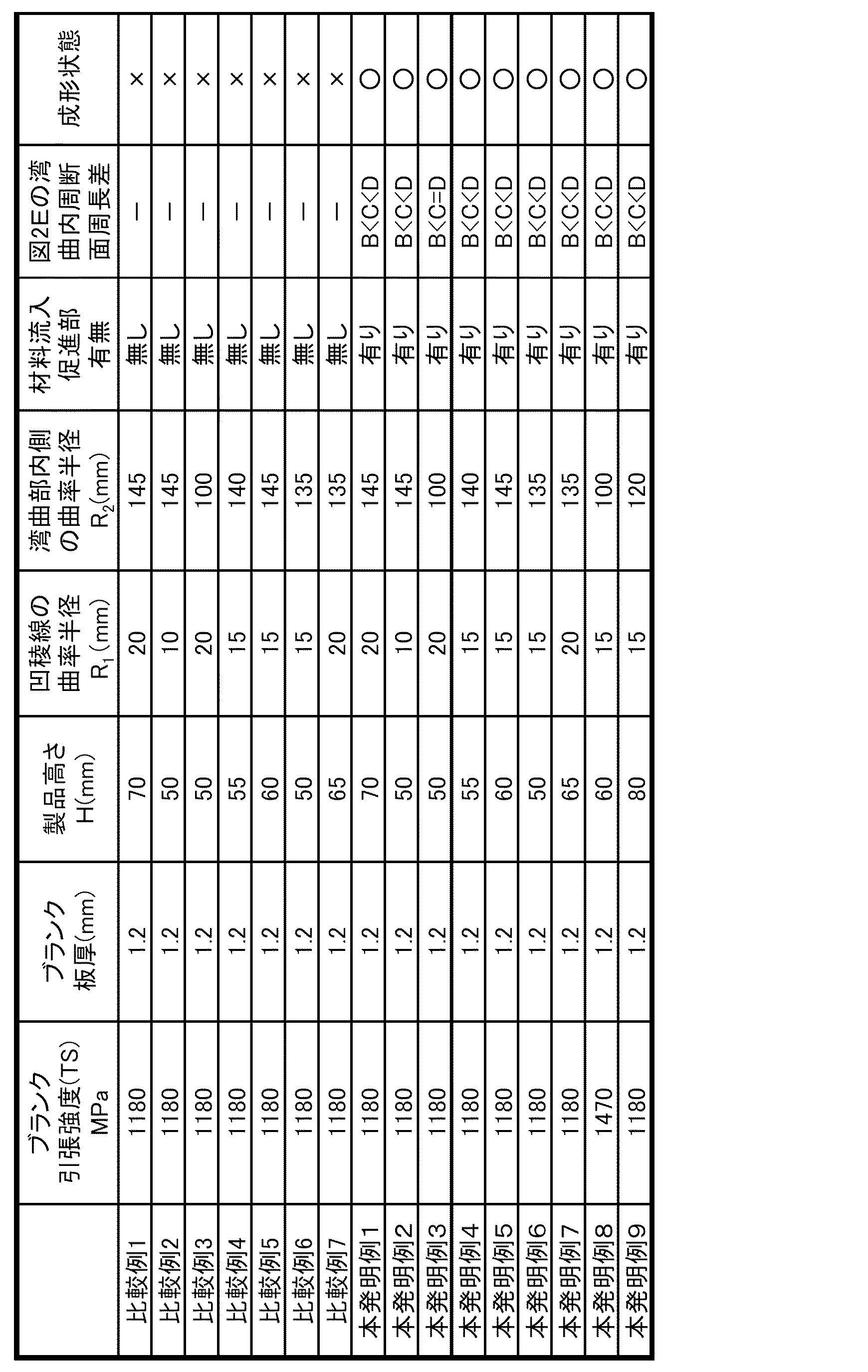
比較例1~7は、引張強度が1180MPaのブランクを用いた絞り成形法を用いたが、いずれも、割れを生じてしまい、図9(a)~図9(c)に示す形状のL型プレス部品1を成形できなかった。これに対し、本発明例1~7では、引張強度が1180,1470MPaのブランクを用いた場合でも、割れを生じることなく良好にL型プレス部品1を成形できた。
1a 湾曲部
8 ブランク
11 天板
12 湾曲部の外側の縦壁
13 湾曲部の外側のフランジ
14 湾曲部の内側の縦壁
15 湾曲部の内側のフランジ
16 湾曲部の内側の凹稜線
17 湾曲部の外側の凹稜線
2 部品
21 天板
22 L字状湾曲の外側の縦壁
23 L字状湾曲の外側のフランジ
24 L字状湾曲の内側の縦壁
25 L字状湾曲の内側のフランジ
3 ブランク
41 ダイ
42 パンチ
43 ブランクホルダ
5 絞りパネル
6 絞りパネル
71 ダイ
72 パンチ
73 ブランクホルダ
74 パッド
75 曲げ型
Claims (17)
- パンチおよびブランクホルダと、パッド、ダイおよび曲げ型との間に配置されたブランクに、下記第1~3の工程を含むプレス加工を行うことによって、長手方向に延在する天板と、該天板の両側につながる2つの縦壁と、該2つの縦壁それぞれにつながる2つの凹稜線と、該2つの凹稜線それぞれにつながる2つのフランジとにより構成されるハット断面を有するとともに、前記天板に直交する平面視で長手方向へ湾曲する湾曲部を有することにより前記平面視でL型の形状を一部または全部に有するプレス部品を製造する方法であって、
下記条件1および2を満足する、プレス部品の製造方法;
第1の工程:前記ブランクにおける前記天板に成形される部分を前記パッドおよび前記パンチにより挟んで保持するとともに、前記ブランクにおける前記天板に成形される部分より前記湾曲部の外側に成形される部分を前記ブランクホルダおよび前記ダイにより挟んで保持する。
第2の工程:前記第1の工程の後に、前記曲げ型を前記パンチが配置されている方向へ相対的に移動して前記ブランクに曲げ成形によるプレス加工を行うことにより、前記湾曲部の内側の縦壁と、該縦壁につながる凹稜線と、該凹稜線につながるフランジとを成形する。
第3の工程:前記第2の工程の後に、前記ブランクを該ブランクホルダおよび該ダイにより挟んで保持したまま、前記ダイおよび前記ブランクホルダを前記パンチが配置されている方向へ相対的に移動して前記ブランクに絞り成形によるプレス加工を行うことにより、前記湾曲部の外側の縦壁と、該縦壁につながる凹稜線と、該凹稜線につながるフランジとを成形する。
[条件1]前記第2の工程により、前記ブランクにおける、前記プレス部品の前記湾曲部の内側のフランジに成形される部分に並んで、材料流入促進部を一つ以上形成する。ただし、前記材料流入促進部は、前記ブランクが前記湾曲部の内側のフランジに成形される部分へ流入する量を増加する。
[条件2]
前記材料流入促進部は、前記天板に直交する平面視で前記湾曲部の内側の中央位置に接する直線と平行でかつ前記天板に直交する方向に沿う断面における断面周長が、前記プレス部品の前記湾曲部の内側のフランジから離れるにつれて増加する断面形状を有する。 - 下記条件3または4を満足する、請求項1に記載のプレス部品の製造方法。
[条件3]前記ブランクが引張強度1180MPa以上の超高張力鋼板からなること、前記プレス部品の高さである前記縦壁の製品高さ方向への投影距離が70mm以上であること、前記プレス部品の前記凹稜線の曲率半径が側面視で10mm以下であること、または、前記プレス部品における前記湾曲部の内側の曲率半径が前記平面視で100mm以下であることのうちの少なくとも一つを満足する。
[条件4]前記ブランクが引張強度1180MPa以上の超高張力鋼板からなること、前記プレス部品の高さである前記縦壁の製品高さ方向への投影距離が55mm以上であること、前記プレス部品の前記凹稜線の曲率半径が側面視で15mm以下であること、または、前記プレス部品における前記湾曲部の内側の曲率半径が前記平面視で140mm以下であることのうちの少なくとも二つ以上を満足する。 - 前記材料流入促進部は、前記ブランクにおける、前記プレス部品に成形される領域の外側の領域に形成される、請求項1または2に記載のプレス部品の製造方法。
- 前記材料流入促進部は、前記断面周長が部分的に一定である請求項1~3のいずれかに記載のプレス部品の製造方法。
- 前記材料流入促進部は、前記フランジと前記天板との並び方向で前記フランジから前記天板に向かう方向へ向けて凸となる凸ビード、または前記フランジと前記天板との並び方向で前記天板から前記フランジに向かう方向へ向けて凸となる凹ビードである、請求項1~4のいずれかに記載のプレス部品の製造方法。
- 前記材料流入促進部は、前記断面周長が段階的に増加する請求項1~5のいずれかに記載のプレス部品の製造方法。
- 前記材料流入促進部は、前記第2の工程の終了時における前記湾曲部の内側の中央位置に接する直線と水平面内で直交する直線を含む垂直断面において、前記ブランクにおける前記湾曲部の内側の凹稜線および前記フランジの会合点に成形される部位と、前記ブランクの縁部とを結ぶことにより得られる外形を有する、請求項1~6のいずれかに記載のプレス部品の製造方法。
- 前記第3の工程の後に下記第4の工程を含む、請求項1~7のいずれかに記載のプレス部品の製造方法:
第4の工程;前記第3の工程により得られた成形品の周囲の一部に残存する、前記材料流入促進部の全部または一部を含む不要部分を除去する。 - パンチおよびブランクホルダと、該パンチおよびブランクホルダに対向して配置されるパッド、ダイおよび曲げ型とを備え、ブランクに下記第1~3の工程を含むプレス加工を行うことによって、長手方向に延在する天板と、該天板の両側につながる2つの縦壁と、該2つの縦壁それぞれにつながる2つの凹稜線と、該2つの凹稜線それぞれにつながる2つのフランジとにより構成されるハット型の断面を有するとともに前記天板に直交する平面視で長手方向へ湾曲する湾曲部を有することにより前記平面視でL型の形状を一部または全部に有するプレス部品を製造するプレス部品の製造装置であって、
下記条件1および2を満足する、プレス部品の製造装置;
第1の工程:前記パッドは、前記パンチとともに、前記ブランクにおける前記天板に成形される部分を挟んで保持するとともに、前記ブランクホルダは、前記ダイとともに、前記ブランクにおける前記天板に成形される部分より前記湾曲部の外側に成形される部分を挟んで保持する。
第2の工程:前記第1の工程の後に、前記曲げ型は、前記パンチが配置されている方向へ相対的に移動して前記ブランクを加工することにより、前記湾曲部の内側の縦壁と、該縦壁につながる凹稜線と、該凹稜線につながるフランジとを成形する。
第3の工程:前記第2の工程の後に、前記ブランクホルダが前記ダイとともに前記ブランクを挟んで保持したまま、前記ダイと前記ブランクホルダが、該ブランクホルダに対して該ブランクホルダが配置されている方向へ相対的に移動して前記ブランクを加工することにより、前記湾曲部の外側の縦壁と該縦壁につながる凹稜線と、該凹稜線につながるフランジを成形することによって、前記プレス部品を成形する。
[条件1]前記曲げ型および前記パンチは、前記第2の工程により、前記ブランクにおける、前記プレス部品の前記湾曲部の内側のフランジに成形される部分に並んで材料流入促進部を一つ以上形成する材料流入促進部形成機構を備える。ただし、前記材料流入促進部は、前記ブランクが前記湾曲部の内側のフランジに成形される部分へ流入する量を増加する。
[条件2]前記材料流入促進部形成機構は、前記材料流入促進部を、前記天板に直交する平面視で前記湾曲部の内周の中央位置に接する直線と平行でかつ前記天板に直交する方向に沿う断面における断面周長が、前記プレス部品の前記湾曲部の内側のフランジから離れるにつれて増加するように、形成する。 - さらに、下記条件3または4を満足する、請求項9に記載のプレス部品の製造装置。
[条件3]前記ブランクが引張強度1180MPa以上の超高張力鋼板からなること、前記プレス部品の高さである前記縦壁の製品高さ方向への投影距離が70mm以上であること、前記プレス部品の前記凹稜線の曲率半径が側面視で10mm以下であること、または、前記プレス部品における前記湾曲部の内側の曲率半径が前記平面視で100mm以下であることのうちの少なくとも一つを満足する。
[条件4]前記ブランクが引張強度1180MPa以上の超高張力鋼板からなること、前記プレス部品の高さである前記縦壁の製品高さ方向への投影距離が55mm以上であること、前記プレス部品の前記凹稜線の曲率半径が側面視で15mm以下であること、または、前記プレス部品における前記湾曲部の内側の曲率半径が前記平面視で140mm以下であることのうちの少なくとも二つ以上を満足する。 - 前記材料流入促進部形成機構は、前記材料流入促進部を、前記ブランクにおける、前記プレス部品に成形される領域の外側の領域に形成する、請求項9または10に記載のプレス部品の製造装置。
- 前記材料流入促進部は、前記断面周長が部分的に一定である請求項9~11のいずれかに記載さのプレス部品の製造装置。
- 前記材料流入促進部は、前記フランジと前記天板との並び方向で前記フランジから前記天板に向かう方向へ向けて凸となる凸ビード、または前記フランジと前記天板との並び方向で前記天板から前記フランジに向かう方向へ向けて凸となる凹ビードである、請求項9~12のいずれかに記載のプレス部品の製造装置。
- 前記材料流入促進部形成機構は、少なくとも、前記第1の工程の終了時に前記ブランクが接触する領域に設けられる、請求項9~13のいずれかに記載のプレス部品の製造装置。
- 前記材料流入促進部形成機構は、前記材料流入促進部を、前記断面周長が段階的に増加するように、形成する、請求項9~14のいずれかに記載のプレス部品の製造装置。
- 前記材料流入促進部形成機構は、前記材料流入促進部を、前記第2の工程の終了時における前記湾曲部の内側の中央位置に接する直線と水平面内で直交する直線を含む垂直断面において、前記ブランクにおける前記湾曲部の内側の凹稜線および前記フランジの会合点に成形される部位と、前記ブランクの縁部とを結ぶことにより得られる外形を有するように、成形する、請求項9~15のいずれかに記載のプレス部品の製造装置。
- 前記第3の工程の後に下記第4の工程を行う装置を備える、請求項9~16のいずれかに記載のプレス部品の製造装置:
第4の工程;前記第3の工程により得られた成形品の周囲の一部に残存する、前記材料流入促進部の全部または一部を含む不要部分を除去する。
Priority Applications (10)
| Application Number | Priority Date | Filing Date | Title |
|---|---|---|---|
| RU2019101905A RU2019101905A (ru) | 2016-06-27 | 2017-06-26 | Способ и устройство для изготовления штампованного компонента |
| CN201780040282.XA CN109414745B (zh) | 2016-06-27 | 2017-06-26 | 冲压部件的制造方法及制造装置 |
| KR1020217006648A KR102407168B1 (ko) | 2016-06-27 | 2017-06-26 | 프레스 부품의 제조 방법 및 제조 장치 |
| MX2018015863A MX2018015863A (es) | 2016-06-27 | 2017-06-26 | Metodo y aparato para producir un componente formado por prensado. |
| EP17820110.9A EP3476500B1 (en) | 2016-06-27 | 2017-06-26 | Method and device for manufacturing pressed component |
| KR1020197002555A KR20190021432A (ko) | 2016-06-27 | 2017-06-26 | 프레스 부품의 제조 방법 및 제조 장치 |
| BR112018077088-4A BR112018077088A2 (pt) | 2016-06-27 | 2017-06-26 | método e aparelho para a produção de componente prensado |
| US16/313,451 US11135633B2 (en) | 2016-06-27 | 2017-06-26 | Method and apparatus for producing pressed component |
| JP2017552099A JP6281670B1 (ja) | 2016-06-27 | 2017-06-26 | プレス部品の製造方法および製造装置 |
| CA3029405A CA3029405A1 (en) | 2016-06-27 | 2017-06-26 | Method and apparatus for producing pressed component |
Applications Claiming Priority (2)
| Application Number | Priority Date | Filing Date | Title |
|---|---|---|---|
| JP2016126247 | 2016-06-27 | ||
| JP2016-126247 | 2016-06-27 |
Publications (1)
| Publication Number | Publication Date |
|---|---|
| WO2018003755A1 true WO2018003755A1 (ja) | 2018-01-04 |
Family
ID=60787141
Family Applications (1)
| Application Number | Title | Priority Date | Filing Date |
|---|---|---|---|
| PCT/JP2017/023450 Ceased WO2018003755A1 (ja) | 2016-06-27 | 2017-06-26 | プレス部品の製造方法および製造装置 |
Country Status (10)
| Country | Link |
|---|---|
| US (1) | US11135633B2 (ja) |
| EP (1) | EP3476500B1 (ja) |
| JP (1) | JP6281670B1 (ja) |
| KR (2) | KR102407168B1 (ja) |
| CN (1) | CN109414745B (ja) |
| BR (1) | BR112018077088A2 (ja) |
| CA (1) | CA3029405A1 (ja) |
| MX (1) | MX2018015863A (ja) |
| RU (1) | RU2019101905A (ja) |
| WO (1) | WO2018003755A1 (ja) |
Cited By (7)
| Publication number | Priority date | Publication date | Assignee | Title |
|---|---|---|---|---|
| JP2020179401A (ja) * | 2019-04-23 | 2020-11-05 | 日本製鉄株式会社 | 熱間プレス成形品の製造方法 |
| EP3915694A4 (en) * | 2019-01-25 | 2022-10-26 | Nippon Steel Corporation | PRESS FORMING PROCESS AND PRESS MACHINE |
| CN115397577A (zh) * | 2020-04-09 | 2022-11-25 | 杰富意钢铁株式会社 | 冲压成形方法以及冲压成形件 |
| CN116689560A (zh) * | 2023-07-25 | 2023-09-05 | 陕西箴铭新材料科技有限公司 | 航空用弧形弯折片成型模具及成型方法 |
| JP2024020697A (ja) * | 2022-08-02 | 2024-02-15 | Jfeスチール株式会社 | 非対称フランジ部を有するプレス成形品の製造方法 |
| WO2024062575A1 (ja) * | 2022-09-21 | 2024-03-28 | 日本製鉄株式会社 | プレス成形品の製造方法及びプレス成形装置 |
| JP7832572B1 (ja) * | 2025-07-07 | 2026-03-18 | 日本製鉄株式会社 | プレス装置、金型およびプレス成形品の製造方法 |
Families Citing this family (24)
| Publication number | Priority date | Publication date | Assignee | Title |
|---|---|---|---|---|
| JP6665958B1 (ja) * | 2019-03-19 | 2020-03-13 | Jfeスチール株式会社 | 車体骨格部品の継手構造、車体骨格部品及び該車体骨格部品の製造方法 |
| CA3135330C (en) * | 2019-03-28 | 2023-06-27 | Honda Motor Co., Ltd. | Press forming method |
| CN110409075B (zh) * | 2019-08-01 | 2023-09-26 | 广东白云学院 | 刺绣垫高装置 |
| EP4011517B1 (en) * | 2019-08-06 | 2025-07-09 | Nippon Steel Corporation | Method for manufacturing press-molded article |
| JP7323824B2 (ja) * | 2019-09-24 | 2023-08-09 | 日本製鉄株式会社 | プレス成形品の製造方法及びプレス成形装置 |
| US12030105B2 (en) * | 2019-09-25 | 2024-07-09 | Nippon Steel Corporation | Structural member, structural member manufacturing method, and structural member manufacturing device |
| WO2021125293A1 (ja) * | 2019-12-18 | 2021-06-24 | 日本製鉄株式会社 | プレス成形品の製造方法およびプレス成形装置、プレス成形ライン |
| WO2021141104A1 (ja) * | 2020-01-08 | 2021-07-15 | 本田技研工業株式会社 | プレス成形方法 |
| JP6923043B1 (ja) * | 2020-05-23 | 2021-08-18 | Jfeスチール株式会社 | プレス成形方法 |
| JP6923044B1 (ja) | 2020-05-23 | 2021-08-18 | Jfeスチール株式会社 | プレス成形金型、プレス成形方法 |
| JP7310712B2 (ja) | 2020-05-23 | 2023-07-19 | Jfeスチール株式会社 | プレス成形方法 |
| JP6981502B2 (ja) * | 2020-05-23 | 2021-12-15 | Jfeスチール株式会社 | プレス成形金型、プレス成形方法 |
| JP7176549B2 (ja) * | 2020-06-30 | 2022-11-22 | Jfeスチール株式会社 | 金属板のせん断加工方法、プレス部品の製造方法、金属板、及び金属板のせん断金型 |
| JP7246349B2 (ja) * | 2020-07-13 | 2023-03-27 | ダイハツ工業株式会社 | プレス成形方法及びプレス成形金型 |
| KR102854846B1 (ko) * | 2020-07-28 | 2025-09-03 | 현대자동차 주식회사 | 차체 부품 열 처리 장치 |
| MX2023002183A (es) * | 2020-09-02 | 2023-03-03 | Jfe Steel Corp | Metodo de fabricacion de componentes prensados, metodo de dise?o de troqueles, dispositivo de dise?o de formas de troqueles y troqueles. |
| WO2022075464A1 (ja) * | 2020-10-09 | 2022-04-14 | 日本製鉄株式会社 | プレス成形品の製造方法、及びプレスライン |
| JP7572935B2 (ja) * | 2021-11-24 | 2024-10-24 | 株式会社神戸製鋼所 | 重ね合わせブランク及びその成形方法 |
| CN119343188A (zh) * | 2022-05-31 | 2025-01-21 | 杰富意钢铁株式会社 | 冲压成型方法和冲压成型件的制造方法 |
| WO2024006051A1 (en) | 2022-06-30 | 2024-01-04 | Cleveland-Cliffs Steel Properties Inc. | Method for prevention of premature edge fracture at draw bead |
| GB2623337B (en) * | 2022-10-13 | 2024-12-25 | Cambridge Entpr Ltd | Working of sheet metal |
| JP7352123B1 (ja) * | 2023-04-04 | 2023-09-28 | 日本製鉄株式会社 | プレス成形品の製造方法 |
| KR20250020805A (ko) | 2023-08-04 | 2025-02-11 | 이채원 | 옆 트임 셔링 티셔츠 |
| JP7798215B1 (ja) * | 2025-01-31 | 2026-01-14 | Jfeスチール株式会社 | プレス成形方法 |
Citations (4)
| Publication number | Priority date | Publication date | Assignee | Title |
|---|---|---|---|---|
| JPS6466024A (en) * | 1987-09-04 | 1989-03-13 | Toyota Motor Corp | Drawing method and press die therefor |
| JP2013035068A (ja) * | 2010-05-19 | 2013-02-21 | Nippon Steel & Sumitomo Metal Corp | L字状形状を有する部品のプレス成形方法 |
| WO2014106932A1 (ja) * | 2013-01-07 | 2014-07-10 | 新日鐵住金株式会社 | プレス部品とその製造方法および製造装置 |
| WO2014185428A1 (ja) * | 2013-05-13 | 2014-11-20 | 新日鐵住金株式会社 | ブランク、成形板、プレス成形品の製造方法及びプレス成形品 |
Family Cites Families (10)
| Publication number | Priority date | Publication date | Assignee | Title |
|---|---|---|---|---|
| SU1196076A1 (ru) | 1983-11-02 | 1985-12-07 | Всесоюзный Ордена Трудового Красного Знамени Заочный Политехнический Институт | Способ выт жки кузовных деталей |
| RU2116854C1 (ru) | 1997-03-27 | 1998-08-10 | Акционерное общество "АвтоВАЗ" | Способ штамповки деталей кузова эластичной средой по жесткой матрице |
| JP4264054B2 (ja) | 2004-06-01 | 2009-05-13 | 株式会社神戸製鋼所 | 曲げ成形方法およびその成形方法に用いる成形金型 |
| JP4306774B2 (ja) | 2007-08-20 | 2009-08-05 | トヨタ自動車株式会社 | プレス成形用金型およびプレス成形方法 |
| RU81932U1 (ru) | 2008-12-29 | 2009-04-10 | Общество с ограниченной ответственностью "СТИГР-ВАГРЕМ" (ООО "СТИГР-ВАГРЕМ") | Дверь салонная пассажирского вагона |
| CN103237611B (zh) | 2010-11-24 | 2015-06-24 | 新日铁住金株式会社 | L形产品的制造方法 |
| JP5510533B1 (ja) | 2012-12-17 | 2014-06-04 | Jfeスチール株式会社 | プレス成形方法 |
| US9592544B2 (en) * | 2012-12-26 | 2017-03-14 | Nissan Motor Co., Ltd. | Draw forming method |
| JP5765496B2 (ja) | 2013-07-19 | 2015-08-19 | Jfeスチール株式会社 | プレス成形方法およびプレス成形部品の製造方法 |
| CN204035335U (zh) | 2014-06-17 | 2014-12-24 | 奇瑞汽车股份有限公司 | 一种汽车侧围板冲压模 |
-
2017
- 2017-06-26 MX MX2018015863A patent/MX2018015863A/es unknown
- 2017-06-26 WO PCT/JP2017/023450 patent/WO2018003755A1/ja not_active Ceased
- 2017-06-26 BR BR112018077088-4A patent/BR112018077088A2/pt not_active Application Discontinuation
- 2017-06-26 CN CN201780040282.XA patent/CN109414745B/zh active Active
- 2017-06-26 EP EP17820110.9A patent/EP3476500B1/en active Active
- 2017-06-26 US US16/313,451 patent/US11135633B2/en active Active
- 2017-06-26 JP JP2017552099A patent/JP6281670B1/ja active Active
- 2017-06-26 KR KR1020217006648A patent/KR102407168B1/ko active Active
- 2017-06-26 KR KR1020197002555A patent/KR20190021432A/ko not_active Ceased
- 2017-06-26 RU RU2019101905A patent/RU2019101905A/ru not_active Application Discontinuation
- 2017-06-26 CA CA3029405A patent/CA3029405A1/en not_active Abandoned
Patent Citations (4)
| Publication number | Priority date | Publication date | Assignee | Title |
|---|---|---|---|---|
| JPS6466024A (en) * | 1987-09-04 | 1989-03-13 | Toyota Motor Corp | Drawing method and press die therefor |
| JP2013035068A (ja) * | 2010-05-19 | 2013-02-21 | Nippon Steel & Sumitomo Metal Corp | L字状形状を有する部品のプレス成形方法 |
| WO2014106932A1 (ja) * | 2013-01-07 | 2014-07-10 | 新日鐵住金株式会社 | プレス部品とその製造方法および製造装置 |
| WO2014185428A1 (ja) * | 2013-05-13 | 2014-11-20 | 新日鐵住金株式会社 | ブランク、成形板、プレス成形品の製造方法及びプレス成形品 |
Non-Patent Citations (1)
| Title |
|---|
| See also references of EP3476500A4 * |
Cited By (10)
| Publication number | Priority date | Publication date | Assignee | Title |
|---|---|---|---|---|
| EP3915694A4 (en) * | 2019-01-25 | 2022-10-26 | Nippon Steel Corporation | PRESS FORMING PROCESS AND PRESS MACHINE |
| JP2020179401A (ja) * | 2019-04-23 | 2020-11-05 | 日本製鉄株式会社 | 熱間プレス成形品の製造方法 |
| JP7172832B2 (ja) | 2019-04-23 | 2022-11-16 | 日本製鉄株式会社 | 熱間プレス成形品の製造方法 |
| CN115397577A (zh) * | 2020-04-09 | 2022-11-25 | 杰富意钢铁株式会社 | 冲压成形方法以及冲压成形件 |
| US12365019B2 (en) | 2020-04-09 | 2025-07-22 | Jfe Steel Corporation | Press forming method and press formed product |
| JP2024020697A (ja) * | 2022-08-02 | 2024-02-15 | Jfeスチール株式会社 | 非対称フランジ部を有するプレス成形品の製造方法 |
| JP7800337B2 (ja) | 2022-08-02 | 2026-01-16 | Jfeスチール株式会社 | 非対称フランジ部を有するプレス成形品の製造方法 |
| WO2024062575A1 (ja) * | 2022-09-21 | 2024-03-28 | 日本製鉄株式会社 | プレス成形品の製造方法及びプレス成形装置 |
| CN116689560A (zh) * | 2023-07-25 | 2023-09-05 | 陕西箴铭新材料科技有限公司 | 航空用弧形弯折片成型模具及成型方法 |
| JP7832572B1 (ja) * | 2025-07-07 | 2026-03-18 | 日本製鉄株式会社 | プレス装置、金型およびプレス成形品の製造方法 |
Also Published As
| Publication number | Publication date |
|---|---|
| US11135633B2 (en) | 2021-10-05 |
| US20190160510A1 (en) | 2019-05-30 |
| JPWO2018003755A1 (ja) | 2018-07-05 |
| EP3476500B1 (en) | 2023-07-26 |
| JP6281670B1 (ja) | 2018-02-21 |
| RU2019101905A (ru) | 2020-07-28 |
| BR112018077088A2 (pt) | 2019-04-02 |
| KR20190021432A (ko) | 2019-03-05 |
| KR102407168B1 (ko) | 2022-06-10 |
| CA3029405A1 (en) | 2018-01-04 |
| EP3476500A1 (en) | 2019-05-01 |
| CN109414745A (zh) | 2019-03-01 |
| KR20210028739A (ko) | 2021-03-12 |
| MX2018015863A (es) | 2019-06-17 |
| EP3476500A4 (en) | 2020-03-18 |
| RU2019101905A3 (ja) | 2020-07-28 |
| CN109414745B (zh) | 2021-11-23 |
Similar Documents
| Publication | Publication Date | Title |
|---|---|---|
| JP6281670B1 (ja) | プレス部品の製造方法および製造装置 | |
| JP6020596B2 (ja) | プレス部品の製造方法およびプレス部品の製造装置 | |
| JP5733475B2 (ja) | 湾曲部品の製造方法及び湾曲部品の製造装置 | |
| JP6119848B2 (ja) | ブランク、成形板、プレス成形品の製造方法及びプレス成形品 | |
| TWI448338B (zh) | 具有l字狀形狀之零件的壓製成形方法 | |
| CN106457341B (zh) | 坯料以及冲压成型品的制造方法 | |
| TWI655038B (zh) | 壓製成形品的製造方法及製造裝置 | |
| CN109641259B (zh) | 压制成形品及其制造方法 | |
| WO2017006793A1 (ja) | プレス部品の製造方法および製造装置 | |
| CN108778549A (zh) | 构造体及其制造方法 |
Legal Events
| Date | Code | Title | Description |
|---|---|---|---|
| ENP | Entry into the national phase |
Ref document number: 2017552099 Country of ref document: JP Kind code of ref document: A |
|
| 121 | Ep: the epo has been informed by wipo that ep was designated in this application |
Ref document number: 17820110 Country of ref document: EP Kind code of ref document: A1 |
|
| ENP | Entry into the national phase |
Ref document number: 3029405 Country of ref document: CA |
|
| NENP | Non-entry into the national phase |
Ref country code: DE |
|
| REG | Reference to national code |
Ref country code: BR Ref legal event code: B01A Ref document number: 112018077088 Country of ref document: BR |
|
| ENP | Entry into the national phase |
Ref document number: 20197002555 Country of ref document: KR Kind code of ref document: A |
|
| ENP | Entry into the national phase |
Ref document number: 2017820110 Country of ref document: EP Effective date: 20190128 |
|
| ENP | Entry into the national phase |
Ref document number: 112018077088 Country of ref document: BR Kind code of ref document: A2 Effective date: 20181226 |